EP0831004A2 - Schienengeleitetes Fahrzeug - Google Patents
Schienengeleitetes Fahrzeug Download PDFInfo
- Publication number
- EP0831004A2 EP0831004A2 EP97890183A EP97890183A EP0831004A2 EP 0831004 A2 EP0831004 A2 EP 0831004A2 EP 97890183 A EP97890183 A EP 97890183A EP 97890183 A EP97890183 A EP 97890183A EP 0831004 A2 EP0831004 A2 EP 0831004A2
- Authority
- EP
- European Patent Office
- Prior art keywords
- sensor
- rail
- guided vehicle
- computer
- drive
- Prior art date
- Legal status (The legal status is an assumption and is not a legal conclusion. Google has not performed a legal analysis and makes no representation as to the accuracy of the status listed.)
- Withdrawn
Links
Images

Classifications
-
- B—PERFORMING OPERATIONS; TRANSPORTING
- B61—RAILWAYS
- B61F—RAIL VEHICLE SUSPENSIONS, e.g. UNDERFRAMES, BOGIES OR ARRANGEMENTS OF WHEEL AXLES; RAIL VEHICLES FOR USE ON TRACKS OF DIFFERENT WIDTH; PREVENTING DERAILING OF RAIL VEHICLES; WHEEL GUARDS, OBSTRUCTION REMOVERS OR THE LIKE FOR RAIL VEHICLES
- B61F5/00—Constructional details of bogies; Connections between bogies and vehicle underframes; Arrangements or devices for adjusting or allowing self-adjustment of wheel axles or bogies when rounding curves
- B61F5/02—Arrangements permitting limited transverse relative movements between vehicle underframe or bolster and bogie; Connections between underframes and bogies
- B61F5/22—Guiding of the vehicle underframes with respect to the bogies
-
- B—PERFORMING OPERATIONS; TRANSPORTING
- B60—VEHICLES IN GENERAL
- B60L—PROPULSION OF ELECTRICALLY-PROPELLED VEHICLES; SUPPLYING ELECTRIC POWER FOR AUXILIARY EQUIPMENT OF ELECTRICALLY-PROPELLED VEHICLES; ELECTRODYNAMIC BRAKE SYSTEMS FOR VEHICLES IN GENERAL; MAGNETIC SUSPENSION OR LEVITATION FOR VEHICLES; MONITORING OPERATING VARIABLES OF ELECTRICALLY-PROPELLED VEHICLES; ELECTRIC SAFETY DEVICES FOR ELECTRICALLY-PROPELLED VEHICLES
- B60L2200/00—Type of vehicles
- B60L2200/26—Rail vehicles
Definitions
- the invention has a rail-guided vehicle, e.g. B. traction vehicle, Waggon, to the object in which a component is transverse is movable to the direction of travel of the vehicle.
- a rail-guided vehicle e.g. B. traction vehicle, Waggon
- Rail-guided vehicles be it rail vehicles or for example magnetic levitation trains u.
- the like will be forever higher speeds, such as significantly above 200 km per hour.
- a corresponding expansion of the route such as banked bends also constructive measures for the vehicles, especially that rolling stock, required. So an aerodynamic cheap training of the vehicles carried out for a corresponding Storage care to be taken u.
- New routes are tried, the desire to have one if possible to achieve rectilinear guidance of the same, as far as possible consider.
- For existing routes and especially for mountainous terrain are the most straightforward guidance of Stretch limits set so that to get higher speeds to reach the trains in curves, not a cant alone is sufficient.
- So-called wagon body inclination systems are used for this purpose have been developed either centrally for one Train or one for each wagon or drive unit of the train Have tilting device.
- the car body is in the The interior of the curve is inclined, which means that driving comfort remains the same of the passengers a higher speed in the curve can be driven.
- a locomotive can also be a Have car body tilt system.
- Speed the possibility of one by centrifugal force counteracting the inclination of the body of the motor vehicle.
- At the body of the locomotive there is one Line arranged with overhead contact line of the pantographs, whereby through the tilting movements, which are speed-dependent, there is a risk that the current collector is no longer in contact with the overhead line. That means top speeds given.
- lateral acceleration forces to avoid under- or overcompensation by the Need to cause.
- the lateral acceleration forces on the one hand recorded as precisely as possible and on the other hand can also be fed to an exact processing.
- the simplest system has a piezoelectric one Circuit on, wherein the output from the piezo crystal Stress is proportional to the forces that occur.
- Such a thing Measuring system enables easy conversion from Forces in electrical quantities, however, are highly sensitive System, so that by natural vibrations of the car body, like they can occur, for example, by rolling it, Disruptions are caused that are exact and timely Control of the transverse movement significantly more difficult.
- Another system is that in the chassis gimbal-mounted gyro is provided.
- the gyroscope endeavors to maintain its plane of rotation. Act Forces on a gyroscope result in movement, namely Deflection of the gyro by 90 ° to the direction of action of the forces, a. Additional forces also occur here, for example with Piezo crystals can be determined.
- This system is too it is peculiar that there is a very high sensitivity, one effective control, in particular regulation of the transverse movement or the pivoting movement of components.
- Laser gyroscopes are also known, which are used in ships, submarines, Airplanes and missiles replace the conventional gyroscope.
- the principle of operation of a laser gyroscope essentially exists in that two laser beams in a triangle, which over Deflecting mirror is formed, run in opposite directions to each other. Becomes the arrangement, for example rotated to the left, requires the left rotating laser beam slightly longer for an entire Orbiting as the right-rotating laser beam. That difference can be determined from the wavefront. It's here particularly sensitive measuring system.
- the deflecting mirror glass fiber spools can also be used, whereby using certain laser diodes from a so-called Fiber gyroscope is spoken.
- Such systems are suitable on the one hand speeds and on the other hand changes of location to eat. Lateral acceleration forces are generated with such a System not measured. It can only be a change of direction or change in speed can be measured.
- GB-2 079 701-A becomes a magnetic levitation train wagon known with car body control.
- the car body lies hiebei over rollers, their axes in the direction of travel of the train are oriented on the chassis. These roles are on one own carrier provided, on the center of which a piston rod is articulated, whereas the corresponding cylinder on the chassis is articulated.
- This cylinder is operated hydraulically.
- either a pump for the Hydraulic fluid or just a valve with a Pressure source is connected to be controlled.
- filters and amplifiers To control individual circuits with detectors, filters and amplifiers provided, both lateral accelerations and Vertical accelerations measured and in electrical quantities are converted, which are used directly for regulation will. Filters and, if necessary, are used to smooth the values integration over time.
- Filters and, if necessary, are used to smooth the values integration over time.
- the present invention has set itself the goal of being a rail-guided Vehicle with a chassis and one across Driving direction to create moving component that allows that Cross movements or swivel movements in rapid succession Perform the lateral acceleration forces, whereby on the one hand, the response times of the sensor should be very short should and on the other hand superimposed vibrations not or only influence the measured variables slightly. Furthermore, the possibility should exist, a link to other parameters enable.
- Another object of the present invention is to create a rail-guided vehicle that is as simple as possible and has a high level of operational reliability having. Furthermore, the sensor should be easy to install and only have a small footprint.
- the present invention is based on a prior art, as given by GB-A-2 079 701.
- the rail-guided vehicle according to the invention for. B. traction vehicle, Waggon, with a chassis, in particular bogie and at least one other component, e.g. B. car body, pantograph, which, based on the chassis, via a Drive can be moved transversely to the direction of travel of the vehicle, in particular is pivotable, the drive via a Sensor which can be influenced via lateral acceleration forces, can be operated, consists essentially in that the sensor with a capacitor is constructed, which is at least one relative to a movable component fixed capacitor plate and at least the one that can be moved by the transverse acceleration forces Has component, and in particular via an analog-digital converter, preferably with a computer, possibly with a time standard, over which the drive controlled, in particular regulated.
- a chassis in particular bogie and at least one other component, e.g. B. car body, pantograph, which, based on the chassis, via a Drive can be moved transversely to the direction of travel of the vehicle, in particular is pivotable,
- a capacitor is used as a sensor for the lateral acceleration forces used so can already when determining the capacity of the capacitor, which has a component that is different from the Lateral acceleration forces can be applied, a smoothing through the inertia of the moving component as well quick response can be achieved.
- the sensor in particular connected to a computer via an analog-digital converter, This means that additional parameters can be used to control the drive be taken into account particularly easily.
- capacitors with a moving component is known for static monitoring of structures, Machine beds, cranes, antenna masts and the like Like. Perform.
- the sensor is constructed with at least two capacitors, then can with the appropriate switching of the same vibrations can be compensated particularly easily because one of the code capacitors serves to deliver a reference voltage, and the other Capacitor is the measuring capacitor, so that a perfect Compensation of the vibrations that overlap the lateral forces, can be reached.
- a wagon is shown in a schematic representation.
- the Bogie 1 has wheels 2 with an axis 3, which over Coil springs 4 carries a bearing part 5, in which a Rotating part 6 is mounted on the pin 7.
- the rotating part 6 has Rollers 8, on which a support body 9 via partially cylindrical Surfaces 10 rests.
- the car body 11 can with the support body 9 be directly connected or, as in the present case, be resiliently connected via additional spring elements 12.
- a hydraulically actuated cylinder-piston unit that on the one hand on the support body 9 and on the other hand on Rotating part 6 is articulated, the support body 9 and thus the Car body 11 inclined to the horizontal in both directions will.
- a sensor 14 On the bogie 1 is a sensor 14 and on and in Car body 1 1 arranged a sensor 15, via which the Lateral acceleration forces can be absorbed via which, as described below, actuates the drive 13 is so that the support body 9 along its part-cylindrical Surfaces 10 can be moved on the rollers 8 of the rotary member 6.
- Fig. 2 is a Stromabnchmer 16 on the roof 17 one Motor vehicle shown.
- the pantograph 16 is along Guides 18 parallel to the roof 17 from a central position, in which of the pantographs is shown, via the drive 13, which via a compressed air cylinder-piston unit is formed in the two end positions left and right movable from the center position shown.
- the pantograph 16 has a pallet 19 which receives the current from the contact wire 20th decreases.
- FIG. 3 shows a current collector 16 which has a pallet 19 has, which is displaceable transversely to the contact wire 20.
- the Drives 13, u. between cylinder-piston units operated with compressed air are both on the pantograph 16 and on the Pallet 19 articulated.
- On the roof 17 of the locomotive can also be formed by a locomotive, for example, are signalers 21 arranged. Through this signal generator 21, which are formed by a photocell with a light source the respective end position of the pallet, referred to the left or right of of the middle position shown.
- On the pallet itself is a ray of light when it is in the end position reflecting surface 22 in the beam path of the signal generator arranged, which one at the respective end position of the pallet high reflection of the signal generator 21 on the Glass fiber conductor 33, which is fixed in position on the current collector 16, emitted light causes so that in the signal generator 21st provided photocell a signal, for example on a Calculator that can pass on, left end position or right end position reached.
- the position of the pallet or the pantograph can be determined also done via the drive itself. Is the drive through a Cylinder-piston unit is formed, so the cylinder can Have windows, to which a fiber optic cable from one Photodiode with light source is directed. The piston can go along of its surface, which is led past the window, with areas have different reflectivities. Through the different intensity of light entering the photodiode arrives, can then on the exact position of the piston in the cylinder Conclusion can be held. Every position of the piston in the cylinder however corresponds to a certain position of the pallet.
- a sensor 23 is shown, the one Has housing 24, in which fixed capacitor plates 25 and as a movable component 26 a liquid, u. between Cyclohexane, arranged with a dielectric constant of 2.0 is.
- the capacitor plates 25 are in a row one behind the other and spaced apart and plunge into the Liquid that forms the movable component 26.
- the Capacitor plates 25 are transverse, in particular normal, to Direction of travel of the rail-guided vehicle arranged. When driving along a straight route the liquid level 27 is oriented, as in FIG. 4a depicted on gravity.
- Capacitor plates such as 7, can be provided, which about an axis 32 in Direction of travel are rotatably mounted so that by loading of centrifugal forces the focus of the moving Capacitor plates 26 is moved towards the outside of the curve. This also changes the capacitance of the capacitor the area in which the fixed capacitor plates 25 and the movable capacitor plates each other cover, is changed.
- FIG. 5 shows a further sensor 23, which as so-called tube condenser is formed.
- the fixed Capacitor plates 25 are through concentrically arranged tubes educated.
- a guide 28 is arranged in the middle of these which the movable component 26, which also by concentrically arranged tubular capacitor plates are formed is that against the force of the spring 29 through that by the centrifugal force actable weight 30 more or less strongly between the fixed tubular capacitor plates 25 inserted will.
- the movable component 26 is the Force overcome the spring 29 accordingly and the movable Component 26 between the fixed capacitor plates 25 immerse and change the capacity.
- the fixed Component is formed by a capacitor plate 25 by a guide 28 is arranged electrically insulated.
- annular capacitor plates are spaced from one another arranged as a movable component 26 by electrically insulating elastically deformable ring elements 31 from each other are separated.
- a weight 30 arranged, which when subjected to centrifugal forces elastically deformable ring elements deformed so that the The distance between the capacitor plates is smaller, with what a change in the capacitance of the capacitor occurs.
- the guide transverse to the direction of travel the rail-guided vehicle is arranged, a measurement of the centrifugal forces in both directions across Direction of travel.
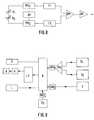
- FIG. 8 shows an electrical block diagram of a sensor, two capacitors K 1 and K 2 being provided, which have a capacitance that can be changed by centrifugal forces.
- the control with current takes place via the astable multivibrator AV, which controls and synchronizes the monostable multivibrators MV 1 and MV 2 , whereby the two monostable multivibrators simultaneously output a voltage level to the capacitors K 1 and K 2 .
- the capacitors K 1 and K 2 are charged via a resistor, not shown.
- the voltages of the capacitors are compared with a voltage standard.
- the resulting pulse-modulated signal which is proportional to the capacitance of the capacitor, passes through filters F 1 and F 2 , in which the high-frequency components of the current, which are due to vibrations, in particular natural frequencies, of the rail-bound vehicle or its components are filtered out will.
- the current then passes into the differential amplifier DV 1 , since the capacitors are also used to suppress interference.
- the current emerging from the differential amplifier DV 1 is amplified in the output amplifier AV and is then fed to the computer, possibly via an analog-digital converter.
- the capacitance of the capacitors K 1 and K 2 is between n farads and p farads.
- the sensor S 1 corresponds to the sensor 15 according to FIG. 1, which is attached to the car body, whereas the sensor S 2 corresponds to the sensor 14, which is provided on the bogie.
- the analog values of the sensors go into the differential amplifier DV 2 , so that the signal coming from the differential amplifier compensates for the inclination of the bogie transverse to the direction of travel and the total inclination of the car body and exposure to centrifugal forces, measured in S 1 .
- the value then reaches the computer R via the analog-digital converter AD 1.
- the sensor T To compensate for the temperature dependence of both the signals from the sensors S 1 and S 2 and the temperature dependence of the amplifier, the sensor T, u.
- thermocouple the temperature is measured and the value is entered into the computer via the analog-digital converter AD 2 , so that, based on a function entered into the computer, in which the temperature is the variable, the respective value of the lateral acceleration forces is determined or the drive A can be actuated as required.
- the speed can be entered into the computer via the sensor S 3 via the analog-digital converter AD 3 .
- the speed is decisive for how quickly the pantograph as well as the pallet and the body are to be moved or swiveled transversely to the direction of travel. At low speeds there is also a risk that the pantograph will be moved in the wrong direction. However, this process can be determined by the end position detection and corrected immediately afterwards.
- this Drive A can also be an electric motor, which has a pinion the arrangement of the components on a rack changes be.
- L can be used, for example, to reach the end position of the Pantograph of the pallet or the car body Computers are reported, with the further possibility of also certain intermediate layers of these components to the computer Report. It is only necessary that appropriate sensors be provided for the respective layers. Corresponds to the current situation of the component not the target position, can be done via the computer control again. Also, if in the computer Timer, e.g. B.
- quartz crystal is provided as the time standard, the Time which was required for the movement can be determined and e.g. B. a warning signal is switched on when a specification is exceeded, the speed is reduced or the pantograph subtracted from.
- the calculator can be used with a Recorder S are provided, each of the current data records.
- the program for the calculator is as follows:
- the program is basically structured so that none Input values can be output at an output, but always the output values depending on certain events be changed, d. that is, there is data encapsulation.
- the Analog values read in via a 10 bit analog-digital converter.
- the read values are then linked mathematically, with what other output values are generated.
- the variables, u. between computer variables, for the storage space in the computer (Placeholder in memory indicates length and type of variable type) To be defined. Then there is a generation of the domestic and Outputs of the inputs and outputs, the initialization of the peripheral blocks, u.
- An interrupt program is also dependent on the time provided, with the time registers required times for a certain movement checked and if necessary a shutdown takes place, for example, the pantograph is removed from the conductor is, with previously a main switch for the power supply to Interruption of the current flow is actuated. So can for example a maximum speed of rolling Materials are prescribed when minimum times for the Pantograph or pallet movement not reached will.
Applications Claiming Priority (3)
| Application Number | Priority Date | Filing Date | Title |
|---|---|---|---|
| AT164796 | 1996-09-18 | ||
| AT0164796A ATA164796A (de) | 1996-09-18 | 1996-09-18 | Schienengeleitetes fahrzeug |
| AT1647/96 | 1996-09-18 |
Publications (2)
| Publication Number | Publication Date |
|---|---|
| EP0831004A2 true EP0831004A2 (de) | 1998-03-25 |
| EP0831004A3 EP0831004A3 (de) | 1999-12-15 |
Family
ID=3517948
Family Applications (1)
| Application Number | Title | Priority Date | Filing Date |
|---|---|---|---|
| EP97890183A Withdrawn EP0831004A3 (de) | 1996-09-18 | 1997-09-15 | Schienengeleitetes Fahrzeug |
Country Status (3)
| Country | Link |
|---|---|
| EP (1) | EP0831004A3 (pt-PT) |
| AT (1) | ATA164796A (pt-PT) |
| CZ (1) | CZ293297A3 (pt-PT) |
Cited By (1)
| Publication number | Priority date | Publication date | Assignee | Title |
|---|---|---|---|---|
| DE102011056180A1 (de) * | 2011-12-08 | 2013-06-13 | Max Bögl Bauunternehmung GmbH & Co. KG | Fahrzeug einer Magnetschwebebahn |
Citations (6)
| Publication number | Priority date | Publication date | Assignee | Title |
|---|---|---|---|---|
| CH600426A5 (en) * | 1976-05-14 | 1978-06-15 | Sig Schweiz Industrieges | Electrohydraulic transverse inclination mechanism |
| GB2032110A (en) * | 1978-05-08 | 1980-04-30 | Secretary Industry Brit | Measuring inclination or acceleration |
| GB2079701A (en) * | 1980-06-23 | 1982-01-27 | Hitachi Ltd | Vehicle tilt control apparatus |
| US4707927A (en) * | 1985-03-18 | 1987-11-24 | Diesel Kiki Co., Ltd. | Inclination and acceleration sensor utilizing electrostatic capacitive effects |
| US5228341A (en) * | 1989-10-18 | 1993-07-20 | Hitachi, Ltd. | Capacitive acceleration detector having reduced mass portion |
| EP0615890A1 (en) * | 1993-03-19 | 1994-09-21 | FIAT FERROVIARIA S.p.A. | Anticentrifugal active lateral suspension for railway vehicles |
-
1996
- 1996-09-18 AT AT0164796A patent/ATA164796A/de not_active Application Discontinuation
-
1997
- 1997-09-15 EP EP97890183A patent/EP0831004A3/de not_active Withdrawn
- 1997-09-17 CZ CZ972932A patent/CZ293297A3/cs unknown
Patent Citations (6)
| Publication number | Priority date | Publication date | Assignee | Title |
|---|---|---|---|---|
| CH600426A5 (en) * | 1976-05-14 | 1978-06-15 | Sig Schweiz Industrieges | Electrohydraulic transverse inclination mechanism |
| GB2032110A (en) * | 1978-05-08 | 1980-04-30 | Secretary Industry Brit | Measuring inclination or acceleration |
| GB2079701A (en) * | 1980-06-23 | 1982-01-27 | Hitachi Ltd | Vehicle tilt control apparatus |
| US4707927A (en) * | 1985-03-18 | 1987-11-24 | Diesel Kiki Co., Ltd. | Inclination and acceleration sensor utilizing electrostatic capacitive effects |
| US5228341A (en) * | 1989-10-18 | 1993-07-20 | Hitachi, Ltd. | Capacitive acceleration detector having reduced mass portion |
| EP0615890A1 (en) * | 1993-03-19 | 1994-09-21 | FIAT FERROVIARIA S.p.A. | Anticentrifugal active lateral suspension for railway vehicles |
Cited By (2)
| Publication number | Priority date | Publication date | Assignee | Title |
|---|---|---|---|---|
| DE102011056180A1 (de) * | 2011-12-08 | 2013-06-13 | Max Bögl Bauunternehmung GmbH & Co. KG | Fahrzeug einer Magnetschwebebahn |
| US9604547B2 (en) | 2011-12-08 | 2017-03-28 | Max Bögl Bauuntemehmung GmbH & Co. KG | Vehicle for a magnetic levitation track |
Also Published As
| Publication number | Publication date |
|---|---|
| EP0831004A3 (de) | 1999-12-15 |
| ATA164796A (de) | 2003-08-15 |
| CZ293297A3 (cs) | 1998-04-15 |
Similar Documents
| Publication | Publication Date | Title |
|---|---|---|
| EP3554919B1 (de) | Gleismessfahrzeug und verfahren zum erfassen einer gleisgeometrie | |
| DE4228414A1 (de) | Verfahren und Vorrichtung zur Aufbereitung von Sensorsignalen | |
| EP3381761B1 (de) | Aktuator zum steuern eines radsatzes eines schienenfahrzeugs | |
| WO2018145829A1 (de) | Verfahren zur berührungslosen erfassung einer gleisgeometrie | |
| EP3553021B1 (de) | Proaktives verringern von schwingungen in einem flurförderzeug | |
| DE19502670A1 (de) | Fahrwerk für Schienenfahrzeuge | |
| EP1038744B1 (de) | Schlingerdämpfer | |
| EP0831004A2 (de) | Schienengeleitetes Fahrzeug | |
| EP2647543B1 (de) | System zur Erfassung von Eigenschaften vorbeifahrender Schienenfahrzeuge | |
| WO1997041022A1 (de) | Schienenfahrzeug mit einem einachsigen laufwerk | |
| DE69730799T2 (de) | Regeleinrichtung zum Halten/zur Positionierung von hängenden Lasten | |
| EP3995792B1 (de) | Verfahren zur lastmessung bei einem transportfahrzeug und transportfahrzeug | |
| DE19913342C2 (de) | Schlingerdämpfer | |
| DE102018217992A1 (de) | Verfahren zum Betreiben eines Aktuators einer aktiven Fahrwerkeinrichtung und aktive Fahrwerkeinrichtung | |
| DE19918140A1 (de) | Meßanordnung zur Regelung von Robotern, Werkzeugmaschinen und dergleichen sowie ein mit dieser Meßanordnung durchgeführtes Meßverfahren | |
| DE4003766C2 (de) | Einrichtung zur Niveauregelung an einem Fahrzeug, insbesondere an einem luftgefederten Fahrzeug | |
| DE4133533A1 (de) | Verfahren zur ist-lage-erfassung von landgebundenen fahrzeugen, insbesondere von mobilen autonomen robotern, von gabelstaplern und dergleichen, und lageerfassungssystem zur durchfuehrung eines solchen verfahrens | |
| AT519579A4 (de) | Vorrichtung zum Messen von Radaufstandskräften eines Schienenfahrzeugs | |
| DE3809639A1 (de) | Verfahren und vorrichtung zur indirekten wegmessung | |
| DE2009190C3 (de) | Prüfgerät zur dynamischen Ermittlung des Reifenzuges eines Fahrzeugrades | |
| DE10217720C1 (de) | Vorrichtung zum Testen einer Radaufhängung an einem Fahrzeug | |
| DE3424979A1 (de) | Fahrwerk fuer radfahrzeuge | |
| AT519972B1 (de) | Anordnung zur Wagenzustandsmessung | |
| DE29921246U1 (de) | Steuervorrichtung zur Überwachung und Regelung von Schwingungsbewegungen von Kranlasten | |
| WO1996003303A1 (de) | Verfahren zur querstabilisierung von schienenfahrzeugen mit gleisbogenabhängiger wagenkastensteuerung |
Legal Events
| Date | Code | Title | Description |
|---|---|---|---|
| PUAI | Public reference made under article 153(3) epc to a published international application that has entered the european phase |
Free format text: ORIGINAL CODE: 0009012 |
|
| AK | Designated contracting states |
Kind code of ref document: A2 Designated state(s): CH DE ES FR IT LI |
|
| AX | Request for extension of the european patent |
Free format text: AL;LT;LV;RO;SI |
|
| PUAL | Search report despatched |
Free format text: ORIGINAL CODE: 0009013 |
|
| AK | Designated contracting states |
Kind code of ref document: A3 Designated state(s): AT BE CH DE DK ES FI FR GB GR IE IT LI LU MC NL PT SE |
|
| AX | Request for extension of the european patent |
Free format text: AL;LT;LV;RO;SI |
|
| 17P | Request for examination filed |
Effective date: 20000613 |
|
| AKX | Designation fees paid |
Free format text: CH DE ES FR IT LI |
|
| 17Q | First examination report despatched |
Effective date: 20000920 |
|
| STAA | Information on the status of an ep patent application or granted ep patent |
Free format text: STATUS: THE APPLICATION IS DEEMED TO BE WITHDRAWN |
|
| 18D | Application deemed to be withdrawn |
Effective date: 20010131 |