US7970022B2 - Surface-emitting fiber laser - Google Patents
Surface-emitting fiber laser Download PDFInfo
- Publication number
- US7970022B2 US7970022B2 US12/161,129 US16112907A US7970022B2 US 7970022 B2 US7970022 B2 US 7970022B2 US 16112907 A US16112907 A US 16112907A US 7970022 B2 US7970022 B2 US 7970022B2
- Authority
- US
- United States
- Prior art keywords
- article
- radiation
- core
- fiber
- waveguide
- Prior art date
- Legal status (The legal status is an assumption and is not a legal conclusion. Google has not performed a legal analysis and makes no representation as to the accuracy of the status listed.)
- Expired - Fee Related, expires
Links
Images


Classifications
-
- H—ELECTRICITY
- H01—ELECTRIC ELEMENTS
- H01S—DEVICES USING THE PROCESS OF LIGHT AMPLIFICATION BY STIMULATED EMISSION OF RADIATION [LASER] TO AMPLIFY OR GENERATE LIGHT; DEVICES USING STIMULATED EMISSION OF ELECTROMAGNETIC RADIATION IN WAVE RANGES OTHER THAN OPTICAL
- H01S3/00—Lasers, i.e. devices using stimulated emission of electromagnetic radiation in the infrared, visible or ultraviolet wave range
- H01S3/05—Construction or shape of optical resonators; Accommodation of active medium therein; Shape of active medium
- H01S3/06—Construction or shape of active medium
- H01S3/063—Waveguide lasers, i.e. whereby the dimensions of the waveguide are of the order of the light wavelength
- H01S3/067—Fibre lasers
-
- G—PHYSICS
- G02—OPTICS
- G02B—OPTICAL ELEMENTS, SYSTEMS OR APPARATUS
- G02B6/00—Light guides; Structural details of arrangements comprising light guides and other optical elements, e.g. couplings
- G02B6/02—Optical fibres with cladding with or without a coating
- G02B6/02295—Microstructured optical fibre
- G02B6/023—Microstructured optical fibre having different index layers arranged around the core for guiding light by reflection, i.e. 1D crystal, e.g. omniguide
- G02B6/02304—Core having lower refractive index than cladding, e.g. air filled, hollow core
-
- H—ELECTRICITY
- H01—ELECTRIC ELEMENTS
- H01S—DEVICES USING THE PROCESS OF LIGHT AMPLIFICATION BY STIMULATED EMISSION OF RADIATION [LASER] TO AMPLIFY OR GENERATE LIGHT; DEVICES USING STIMULATED EMISSION OF ELECTROMAGNETIC RADIATION IN WAVE RANGES OTHER THAN OPTICAL
- H01S3/00—Lasers, i.e. devices using stimulated emission of electromagnetic radiation in the infrared, visible or ultraviolet wave range
- H01S3/02—Constructional details
- H01S3/022—Constructional details of liquid lasers
-
- H—ELECTRICITY
- H01—ELECTRIC ELEMENTS
- H01S—DEVICES USING THE PROCESS OF LIGHT AMPLIFICATION BY STIMULATED EMISSION OF RADIATION [LASER] TO AMPLIFY OR GENERATE LIGHT; DEVICES USING STIMULATED EMISSION OF ELECTROMAGNETIC RADIATION IN WAVE RANGES OTHER THAN OPTICAL
- H01S3/00—Lasers, i.e. devices using stimulated emission of electromagnetic radiation in the infrared, visible or ultraviolet wave range
- H01S3/05—Construction or shape of optical resonators; Accommodation of active medium therein; Shape of active medium
- H01S3/06—Construction or shape of active medium
- H01S3/063—Waveguide lasers, i.e. whereby the dimensions of the waveguide are of the order of the light wavelength
- H01S3/067—Fibre lasers
- H01S3/06708—Constructional details of the fibre, e.g. compositions, cross-section, shape or tapering
- H01S3/06729—Peculiar transverse fibre profile
- H01S3/06741—Photonic crystal fibre, i.e. the fibre having a photonic bandgap
-
- H—ELECTRICITY
- H01—ELECTRIC ELEMENTS
- H01S—DEVICES USING THE PROCESS OF LIGHT AMPLIFICATION BY STIMULATED EMISSION OF RADIATION [LASER] TO AMPLIFY OR GENERATE LIGHT; DEVICES USING STIMULATED EMISSION OF ELECTROMAGNETIC RADIATION IN WAVE RANGES OTHER THAN OPTICAL
- H01S3/00—Lasers, i.e. devices using stimulated emission of electromagnetic radiation in the infrared, visible or ultraviolet wave range
- H01S3/05—Construction or shape of optical resonators; Accommodation of active medium therein; Shape of active medium
- H01S3/06—Construction or shape of active medium
- H01S3/063—Waveguide lasers, i.e. whereby the dimensions of the waveguide are of the order of the light wavelength
- H01S3/067—Fibre lasers
- H01S3/0675—Resonators including a grating structure, e.g. distributed Bragg reflectors [DBR] or distributed feedback [DFB] fibre lasers
-
- H—ELECTRICITY
- H01—ELECTRIC ELEMENTS
- H01S—DEVICES USING THE PROCESS OF LIGHT AMPLIFICATION BY STIMULATED EMISSION OF RADIATION [LASER] TO AMPLIFY OR GENERATE LIGHT; DEVICES USING STIMULATED EMISSION OF ELECTROMAGNETIC RADIATION IN WAVE RANGES OTHER THAN OPTICAL
- H01S3/00—Lasers, i.e. devices using stimulated emission of electromagnetic radiation in the infrared, visible or ultraviolet wave range
- H01S3/09—Processes or apparatus for excitation, e.g. pumping
- H01S3/091—Processes or apparatus for excitation, e.g. pumping using optical pumping
- H01S3/094—Processes or apparatus for excitation, e.g. pumping using optical pumping by coherent light
- H01S3/094003—Processes or apparatus for excitation, e.g. pumping using optical pumping by coherent light the pumped medium being a fibre
-
- H—ELECTRICITY
- H01—ELECTRIC ELEMENTS
- H01S—DEVICES USING THE PROCESS OF LIGHT AMPLIFICATION BY STIMULATED EMISSION OF RADIATION [LASER] TO AMPLIFY OR GENERATE LIGHT; DEVICES USING STIMULATED EMISSION OF ELECTROMAGNETIC RADIATION IN WAVE RANGES OTHER THAN OPTICAL
- H01S3/00—Lasers, i.e. devices using stimulated emission of electromagnetic radiation in the infrared, visible or ultraviolet wave range
- H01S3/23—Arrangements of two or more lasers not provided for in groups H01S3/02 - H01S3/22, e.g. tandem arrangements of separate active media
- H01S3/2383—Parallel arrangements
Definitions
- This disclosure relates to fiber lasers.
- Optical fibers are waveguides with a well-defined axis of propagation that typically include a core and a cladding that surrounds the core.
- the core material has a higher refractive index than the cladding material, and the optical fiber guides radiation along a waveguide axis by confining the radiation within the core due to total internal reflection of the radiation at the core-cladding interface.
- Fiber lasers are typically composed of optical fibers in which the core is doped with a gain medium.
- a pair of reflectors e.g., mirrors or fiber Bragg gratings
- the gain medium is pumped, e.g., by pump radiation directed into the core.
- Radiation emission from the pumped gain medium is amplified through feedback within the optical cavity, while being guided back and forth between the reflectors and confined to the core. Generally, some of this radiation is transmitted by at least one of the reflectors and exits the fiber at an end of the fiber.
- Embodiments feature a fiber waveguide utilizing a photonic bandgap radiation confinement structure that has a dual purpose of both guiding the pump radiation along the fiber's axis and the confinement of the laser radiation in the transverse direction.
- the disclosure features an article, including a fiber waveguide extending along a waveguide axis, the fiber waveguide including a core extending along the waveguide axis and a confinement region surrounding the core.
- the confinement region is configured to guide radiation at a first wavelength, ⁇ 1 , along the waveguide axis and is configured to transmit at least some of the radiation (e.g., about 10% or more, about 25% or more, about 50% or more, about 75% or more, about 90% or more) at a second wavelength, ⁇ 2 , incident on the confinement region along a path, where ⁇ 1 and ⁇ 2 are different.
- the core includes a core material selected to interact with radiation at ⁇ 1 to produce radiation at ⁇ 2 .
- the fiber waveguide can be configured to provide stimulated emission of radiation at ⁇ 2 in a direction orthogonal to the waveguide axis when radiation of sufficient power at ⁇ 1 is directed to the core.
- the stimulated emission can be asymmetric with respect to the waveguide axis when the radiation at ⁇ 2 directed to the core is linearly polarized.
- the asymmetric emission can have a dipole-shaped intensity pattern with respect to the waveguide axis.
- the stimulated emission can occur along a portion of the fiber waveguide that extends about 10 ⁇ 2 or more along the waveguide axis. In some embodiments, the stimulated emission occurs along a portion of the fiber waveguide that extends about 1 mm or more along the waveguide axis.
- the core can have a diameter in a range from 1 ⁇ m to about 1,000 ⁇ m.
- the core can be configured to support one or more cavity modes at wavelengths at or near ⁇ 2 .
- the article can have a quality factor, Q, of about 500 or more for at least one of the modes.
- the confinement region can have a plurality of high refractive index regions alternating with low refractive index regions in a direction orthogonal to the waveguide axis.
- the plurality of low refractive index regions can correspond to holey portions of the confinement regions.
- the plurality of alternating high and low refractive index portions correspond to alternating layers of a first material and a second material, the first material having a high refractive index and the second material having a low refractive index.
- the alternating layers can define a structure having a spiral cross section with respect to the waveguide axis.
- the spiral structure can include a multilayer structure comprising at least two layers of the different materials encircling the core multiple times.
- the confinement region can be configured to provide a photonic band gap for radiation at ⁇ 1 .
- the confinement region can be configured to reflect sufficient radiation at ⁇ 2 to provide sufficient optical feedback for lasing at ⁇ 2 when radiation of sufficient power at ⁇ 1 is directed to the core.
- ⁇ 1 and ⁇ 2 can be in a range from about 300 nm to about 15,000 nm.
- the core material can include a gain medium.
- the gain medium can be an organic material.
- the gain medium can include a dye.
- the core material includes a matrix material and the gain medium is dispersed in the matrix material.
- the matrix material can be a polymer.
- the core material is a solid material at room temperature.
- the core material can be a fluid (e.g., a liquid) at room temperature.
- the fiber waveguide can include segments where the core is devoid of the core material.
- the article includes a light source configured to produce radiation at ⁇ 1 and arranged to direct the radiation at ⁇ 1 into the core.
- the light source can be a laser light source.
- the disclosure features a method that includes providing a fiber waveguide configured to guide radiation at a wavelength ⁇ 1 along a waveguide axis, the fiber waveguide including a core extending along the waveguide axis having a core material selected to interact with radiation at ⁇ 1 to produce radiation at ⁇ 2 .
- the method includes directing radiation at ⁇ 1 into the core at an intensity sufficient to cause emission of radiation at ⁇ 2 from the fiber waveguide in a direction orthogonal to the waveguide axis.
- the method can include moving the position of a gain medium in the fiber to vary the position in the fiber which emits the radiation at ⁇ 2 .
- the method can be implemented using the article discussed above and can include one or more of the features associated therewith.
- embodiments include fiber lasers that offer control over position, direction, and polarization of the laser emission wavefront.
- the fiber lasers are inherently scaleable to different wavelengths.
- Embodiments can be used for a variety of applications, including remote delivery of radial laser emission.
- embodiments allow for control of the position of the gain medium, and hence emission location, along the length of a fiber waveguide.
- fiber lasers can provide transverse surface laser emission from a large area. Such embodiments can be used, for example, in applications that require low profile laser geometry, such as endoscope phototherapy.
- Embodiments can allow simple integration of multi-fiber, large area, low-profile, flexible coherent light source into various articles.
- fiber lasers can be woven into textiles, providing textiles capable of laser emission.
- FIG. 1A is a cross-sectional view of an embodiment of fiber laser including a photonic crystal fiber waveguide from a perspective orthogonal to the fiber's waveguide axis.
- FIG. 1B is a cross-sectional view of the embodiment of the fiber laser shown in FIG. 1A from a perspective parallel to the fiber's waveguide axis.
- FIG. 1C is a plot of the refractive index profile of a part of the fiber laser shown in FIG. 1A .
- FIG. 2A-2D are schematic diagrams showing steps in a method for making a fiber laser.
- FIG. 3 is a schematic diagram of a system including an edge-emitting fiber laser.
- FIG. 4 is a schematic of a fiber laser including multiple discrete portions which emit laser radiation.
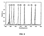
- FIG. 5 is a plot of emission spectra of fiber lasers including different gain media.
- FIG. 6A is a plot showing emission from a fiber laser at different pump radiation intensities.
- FIG. 6B is a plot showing emission energy as a function of pump intensity for fiber lasers including the same dye at different concentrations.
- FIG. 6C is an emission spectrum of a fiber laser.
- FIG. 7A is an angular intensity pattern for a fiber laser showing the dependence of laser emission intensity for different pump radiation polarization.
- FIG. 7B is a plot showing laser emission intensity as a function of analyzer orientation.
- a fiber laser 100 includes a core 120 extending along a waveguide axis and a confinement region 110 (e.g., alternating high index and low index layers) surrounding the core.
- Confinement region 110 is surrounded by a support layer 150 , which provides mechanical support for the confinement region.
- Core 120 includes a gain medium and a matrix through which the gain medium is dispersed.
- the gain medium in core 120 is pumped by directing radiation at a pump wavelength, ⁇ p , through the core.
- Pump radiation depicted as rays 101 in FIG. 1B
- the gain medium emits light at a wavelength ⁇ 1 , at least some of which is reflected by confinement region 110 providing optical feedback.
- At least some of the emitted radiation is transmitted through the confinement region and exits fiber 100 through fiber's side walls.
- Radiation at ⁇ 1 propagating in the radial direction i.e., orthogonal to waveguide axis 199 ) is depicted by rays 102 in core 120 .
- the light emitted by fiber laser 100 in the radial direction is depicted by rays 103 .
- the intensity of the pump radiation is above the lasing threshold, stimulated emission occurs in the gain medium, and emission from the side of fiber 100 at ⁇ 1 is laser radiation.
- the photonic band gap structure performs a dual role enabled by the characteristic shift of the band edges to shorter wavelengths (higher frequencies) with increase in axial wave vector.
- the blue-shifted bandgap having axial wave vectors near the light line is responsible for guiding the pump radiation.
- the photonic band gap structure exhibits a reflection spectrum with high reflectance (e.g., close to 100%) for a band of wavelengths ⁇ pbg .
- ⁇ pbg generally depends on the structure and composition of the confinement region (see discussion below).
- ⁇ pbg should be selected so that the band of wavelengths emitted from the pumped gain medium is overlapped with ⁇ pbg .
- the gain medium, structure of the confinement region, and pump wavelength are all selected based on the desired laser wavelength, ⁇ 1 , which can be in the ultraviolet, visible, or infrared portions of the electromagnetic spectrum.
- ⁇ p depends on the type of gain medium being used. ⁇ p is generally less than ⁇ 1 , and can be in the ultraviolet, visible, or infrared portions of the electromagnetic spectrum.
- the pump radiation is provided by a pump radiation source capable of producing radiation at ⁇ p .
- the pump radiation source is a monochromatic source, delivering radiation exclusively at ⁇ p .
- the pump radiation source is a broadband source, delivering radiation at multiple wavelengths, including ⁇ p .
- the pump radiation source can be a laser light source (e.g., a solid state laser, a gas laser, a diode laser, a fiber laser) or a regular light source (e.g., a solid state light source such as a light emitting diode, a fluorescent light source, an incandescent light source).
- Pump radiation can be delivered continuously or in pulses.
- the input power of the pump radiation is selected based on the desired intensity of laser emission from fiber laser 100 . Accordingly, the pump radiation is delivered with sufficient power to cause lasing in fiber laser 100 (i.e., above the lasing threshold). Typically, the pump radiation power is below the threshold for damaging the fiber laser.
- the pump radiation can be polarized or unpolarized.
- the pump radiation is linearly polarized.
- Linearly polarized pump radiation can result in anisotropic laser emission in the radial direction.
- the laser emission can have a dipole-like wavefront oriented, for example, in the polarization direction (i.e., parallel to the electric field vector) of the linearly polarized pump radiation.
- core 120 has a diameter that can vary as desired. In general, smaller cores will result in higher power density of the pump radiation for a certain input pump power and therefore lower threshold. Accordingly, the core size can be selected based on characteristics of the pump radiation source so that there is a desired power density of pump radiation during operation. Additionally, the core diameter can be selected based on the desired mode characteristics of the guided pump radiation and/or of the emitted radiation. In some embodiments, the core diameter is selected so that the fiber is a single mode fiber for ⁇ p .
- the core diameter can be on the order of about ⁇ p .
- the core diameter can be larger ⁇ p , such as about 5 ⁇ p or more (e.g., about 10 ⁇ p or more, about 20 ⁇ p or more, about 30 ⁇ p or more, about 40 ⁇ p or more, about 50 ⁇ p or more, about 100 ⁇ p or more).
- the core diameter is in a range from about 1 ⁇ m to about 1,000 ⁇ m (e.g., about 10 ⁇ m or more, about 50 ⁇ m or more, about 100 ⁇ m or more, about 500 ⁇ m or less, about 200 ⁇ m or less).
- the power density of the pump radiation should be above the threshold power required for lasing, but should be below the threshold for which the fiber is damaged.
- the gain medium is selected based on the desired emission wavelength, ⁇ 1 .
- the gain medium can be an organic or inorganic gain medium.
- organic gain media include organic dyes, such as LDS698, DCM, coumarin 503, coumarin 500, coumarin 540A, rhodamine 590, oxazine 720, oxazine 725, and LD700 (all commercially available from Exciton, Inc., Dayton, Ohio), quantum dots, conjugated polymers.
- inorganic gain media include the rare-earth ions: Erbium, Neodymium, and Praseodymium.
- the gain medium is dispersed in a matrix material.
- the matrix material can vary as desired.
- the matrix material is selected based on its compatibility with the gain medium and with the processes used in the formation of the fiber laser.
- Matrix materials are also selected based on their optical properties, particularly at ⁇ p and ⁇ 1 .
- matrix materials typically should have relatively low absorption at ⁇ p and ⁇ 1 .
- Matrix materials can include solid or liquid materials. Examples of solid matrix materials include polymers (e.g., homopolymers or copolymers) and inorganic glasses. Examples of liquid matrix materials include water and organic liquids.
- the concentration of the gain medium in the matrix material can vary as desired. Generally, the higher the concentration of the gain medium, the lower the threshold input power required for lasing. For some gain media, such as certain organic dyes, for very high concentration, the physical proximity of the molecules can result in degraded emission. In some embodiments, the concentration of the gain medium is 10 ppm or more (e.g., about 50 ppm or more, about 100 ppm or more, about 500 ppm or more, about 1,000 ppm or more).
- confinement region 110 includes continuous alternating layers 130 and 140 of materials (e.g., polymer, glass) having different refractive indices. Continuous layers 130 and 140 form a spiral around an axis 199 along which the photonic crystal fiber waveguide guides electromagnetic radiation.
- materials e.g., polymer, glass
- One of the layers is a high-index layer having an index n H and a thickness d H
- the layer e.g., layer 130
- the layer is a low-index layer having an index n L and a thickness d L
- n H >n L e.g., n H ⁇ n L can be greater than or equal to or greater than 0.01, 0.05, 0.1, 0.2, 0.5 or more.
- the spiraled layers provide a periodic variation in the index of refraction along radial section 160 , with a period corresponding to the optical thickness of layer 130 and layer 140 , i.e., confinement region 110 has an bilayer optical period n H d H +n L d L .
- the thickness (d H and d L ) and optical thickness (n H d H and n L d L ) of layers 130 and 140 can vary depending on the desired optical characteristics of the confinement region. In some embodiments, the optical thickness of layer 130 and layer 140 are the same. Layer thickness is usually selected based on the desired optical performance of the fiber (e.g., according to the ⁇ p and ⁇ 1 ). The relationship between layer thickness and optical performance is discussed below. Typically, layer thickness is in the sub-micron to tens of micron range. For example, layers 130 and 140 can be between about 0.1 ⁇ m to 20 ⁇ m thick (e.g., about 0.5 to 5 ⁇ m thick).
- confinement region 110 may include different numbers of bilayers (e.g., about 10 or more bilayers, about 20 or more bilayers, about 30 or more bilayers, about 40 or more bilayers).
- layer 140 includes a material that has a high refractive index, such as a chalcogenide glass.
- Layer 130 includes a material having a refractive index lower than the high index material of layer 140 , and is typically mechanically flexible.
- layer 130 can be formed from a polymer, such as PEI.
- PEI polymer
- the materials forming layer 130 and layer 140 can be co-drawn.
- materials with a suitably high index of refraction to form a high index portion include chalcogenide glasses (e.g., glasses containing a chalcogen element, such as sulphur, selenium, and/or tellurium), heavy metal oxide glasses, amorphous alloys, and combinations thereof.
- chalcogenide glasses e.g., glasses containing a chalcogen element, such as sulphur, selenium, and/or tellurium
- heavy metal oxide glasses e.g., amorphous alloys, and combinations thereof.
- chalcogenide glasses may include one or more of the following elements: boron, aluminum, silicon, phosphorus, sulfur, gallium, germanium, arsenic, indium, tin, antimony, thallium, lead, bismuth, cadmium, lanthanum and the halides (fluorine, chlorine, bromide, iodine).
- Chalcogenide glasses can be binary or ternary glasses, e.g., As—S, As—Se, Ge—S, Ge—Se, As—Te, Sb—Se, As—S—Se, S—Se—Te, As—Se—Te, As—S—Te, Ge—S—Te, Ge—S—Te, Ge—S—Se, As—Ge—Se, As—Ge—Te, As—Se—Pb, As—S—Tl, As—Se—Tl, As—Te—Tl, As—Se—Ga, Ga—La—S, Ge—Sb—Se or complex, multi-component glasses based on these elements such as As—Ga—Ge—S, Pb—Ga—Ge—S, etc.
- a chalcogenide glass with a suitably high refractive index may be formed with 5-30 mole % Arsenic, 20-40 mole % Germanium, and 30-60 mole % Selenium.
- heavy metal oxide glasses with high refractive indices include Bi 2 O 3 —, PbO—, Tl 2 O 3 —, Ta 2 O 3 —, TiO 2 —, and TeO 2 — containing glasses.
- Materials with suitably low index of refraction to form a low-index portion include oxide glasses, halide glasses, polymers, and combinations thereof.
- Polymers including those in the carbonate- (e.g., polycarbonate (PC)), sulfone- (e.g., poly(ether sulphone) (PES)), etherimid- (e.g., poly(etherimide) (PEI)), and acrylate- (e.g., poly(methyl methacrylate) (PMMA)) families as well as fluoropolymers are good matching candidates too.
- Suitable oxide glasses may include glasses that contain one or more of the following compounds: 0-40 mole % of M 2 O where M is Li, Na, K, Rb, or Cs; 0-40 mole % of M′O where M′ is Mg, Ca, Sr, Ba, Zn, or Pb; 0-40 mole % of M′′ 2 O 3 where M′′ is B, Al, Ga, In, Sn, or Bi; 0-60 mole % P 2 O 5 ; and 0-40 mole % SiO 2 .
- Portions of fiber lasers can optionally include other materials.
- any portion can include one or more materials that change the index of refraction of the portion.
- a portion can include a material that increases the refractive index of the portion.
- Such materials include, for example, germanium oxide, which can increase the refractive index of a portion containing a borosilicate glass.
- a portion can include a material that decreases the refractive index of the portion.
- boron oxide can decrease the refractive index of a portion containing a borosilicate glass.
- Portions of fiber lasers can be homogeneous or inhomogeneous.
- one or more portions can include nano-particles (e.g., particles sufficiently small to minimally scatter light at guided wavelengths) of one material embedded in a host material to form an inhomogeneous portion.
- nano-particles e.g., particles sufficiently small to minimally scatter light at guided wavelengths
- An example of this is a high-index polymer composite formed by embedding a high-index chalcogenide glass nano-particles in a polymer host.
- Further examples include CdSe and or PbSe nano-particles in an inorganic glass matrix.
- Portions of fiber waveguides can include materials that alter the mechanical, rheological and/or thermodynamic behavior of those portions of the fiber.
- one or more of the portions can include a plasticizer.
- Portions may include materials that suppress crystallization, or other undesirable phase behavior within the fiber.
- crystallization in polymers may be suppressed by including a cross-linking agent (e.g., a photosensitive cross-linking agent).
- a nucleating agent such as TiO 2 or ZrO 2 , can be included in the material.
- Portions can also include compounds designed to affect the interface between adjacent portions in the fiber (e.g., between the low index and high index layers).
- Such compounds include adhesion promoters and compatibilizers.
- an organo-silane compound can be used to promote adhesion between a silica-based glass portion and a polymer portion.
- phosphorus or P 2 O 5 is compatible with both chalcogenide and oxide glasses, and may promote adhesion between portions formed from these glasses.
- Confinement region 110 guides radiation in a first range of wavelengths to propagate in dielectric core 120 along waveguide axis 199 .
- the confinement mechanism is based on a photonic crystal structure in region 110 that forms a bandgap including the first range of wavelengths. Because the confinement mechanism is not index-guiding, it is not necessary for the core to have a higher index than that of the portion of the confinement region immediately adjacent the core. To the contrary, core 120 may have a lower average index than that of confinement region 110 .
- Layers 130 and 140 of confinement region 110 form what is known as a Bragg fiber.
- the periodic optical structure of the spirally wound layers are analogous to the alternating layers of a planar dielectric stack reflector (which is also known as a Bragg mirror).
- the layers of confinement region 110 and the alternating planar layers of a dielectric stack reflector are both examples of a photonic crystal structure. Photonic crystal structures are described generally in Photonic Crystals by John D. Joannopoulos et al. (Princeton University Press, Princeton N.J., 1995).
- a photonic crystal is a structure with a refractive index modulation that produces a photonic bandgap in the photonic crystal.
- a photonic bandgap is a range of wavelengths (or inversely, frequencies) in which there are no accessible extended (i.e., propagating, non-localized) states in the dielectric structure.
- the structure is a periodic structure, but it may also include, e.g., more complex “quasi-crystals.”
- the bandgap can be used to confine, guide, and/or localize light by combining the photonic crystal with “defect” regions that deviate from the bandgap structure.
- accessible states means those states with which coupling is not already forbidden by some symmetry or conservation law of the system. For example, in two-dimensional systems, polarization is conserved, so only states of a similar polarization need to be excluded from the bandgap. In a waveguide with uniform cross-section (such as a typical fiber), the wave vector ⁇ is conserved, so only states with a given ⁇ need to be excluded from the bandgap to support photonic crystal guided modes.
- the “angular momentum” index m is conserved, so only modes with the same m need to be excluded from the bandgap.
- the requirements for photonic bandgaps are considerably relaxed compared to “complete” bandgaps in which all states, regardless of symmetry, are excluded.
- the reflector formed from the stack of layers is highly reflective in the photonic bandgap because EM radiation cannot propagate through the stack.
- the layers in confinement region 110 provide confinement because they are highly reflective for incident rays in the bandgap. Strictly speaking, a photonic crystal is only completely reflective in the bandgap when the index modulation in the photonic crystal has an infinite extent. Otherwise, incident radiation can “tunnel” through the photonic crystal via an evanescent mode that couples propagating modes on either side of the photonic crystal. In theory, however, the rate of such tunneling decreases exponentially with photonic crystal thickness (e.g., the number of alternating layers). It also decreases with the magnitude of the index-contrast in the confinement region.
- a photonic bandgap may extend over only a relatively small region of propagation vectors.
- a layer stack may be highly reflective for a normally incident ray and yet only partially reflective for an obliquely incident ray.
- a “complete photonic bandgap” is a bandgap that extends over all possible wave vectors and all polarizations.
- a complete photonic bandgap is only associated with a photonic crystal having index modulations along three dimensions.
- the high-index layers may vary in index and thickness, and/or the low-index layers may vary in index and thickness.
- the confinement region may also include a periodic structure including more than two layers per period (e.g., three or more layers per period).
- the refractive index modulation may vary continuously or discontinuously as a function of fiber radius within the confinement region.
- the confinement region may be based on any index modulation that creates a photonic bandgap.
- multilayer structure 110 forms a Bragg reflector because it has a periodic index variation with respect to the radial axis.
- the quarter-wave condition becomes:
- this equation may not be exactly optimal because the quarter-wave condition is modified by the cylindrical geometry, which may require the optical thickness of each layer to vary smoothly with its radial coordinate. Nonetheless, we find that this equation provides an excellent guideline for optimizing many desirable properties, especially for core radii larger than the mid-bandgap wavelength.
- confinement region 110 includes a multilayer structure that is wrapped around the core multiple times to provide a spiral structure
- the confinement region can include annular layers as an alternative or in addition to the spiral layers.
- the confinement region can include a two-dimensional refractive index modulation.
- holey fibers such as those described by M. D. Nielsen et al. in “Low-loss photonic crystal fibers for data transmission and their dispersion properties,” Opt. Express 12, 1372, (2004), can be used.
- support layer 150 provides mechanical support for confinement region 110 .
- the thickness of support layer 150 can vary as desired.
- support layer 150 is substantially thicker than confinement region 110 .
- support layer 150 can be about 10 or more times thicker than confinement region 110 (e.g., more than about 20, about 30, or about 50 times thicker).
- the composition of support layer 150 is usually selected to provide the desired mechanical support and protection for confinement region 110 , while at the same time being sufficiently transparent at ⁇ 1 to allow the laser radiation to be emitted by the side of the fiber.
- support layer 150 is formed from materials that can be co-drawn with the confinement region 110 .
- support layer can be formed from the same material(s) as used to form confinement region 110 .
- layer 130 is formed from a polymer
- support layer 150 can be formed from the same polymer.
- fiber lasers can be made in a variety of different ways.
- fiber lasers such as laser 100
- fiber lasers can be made by rolling a planar multilayer article into a spiral structure and drawing a photonic crystal fiber from a preform derived from the spiral structure. After drawing, a gain medium can be introduced into the hollow core of the fiber.
- a glass is deposited 220 on a surface 211 of a polymer film 210 .
- the glass can be deposited by methods including thermal evaporation, chemical vapor deposition, or sputtering.
- the deposition process provides a multilayer article 240 composed of a layer 230 of glass on polymer film 210 .
- multilayer film 240 is rolled around a mandrel 255 (e.g., a hollow glass, such as a borosilicate glass, or polymer tube) to form a spiral tube.
- a mandrel 255 e.g., a hollow glass, such as a borosilicate glass, or polymer tube
- a number (e.g., about three to ten) of polymer films are then wrapped around the spiral tube to form a preform wrap.
- the polymer films are made from the same polymer or glass used to form multilayer article.
- the preform wrap is heated to a temperature above the glass transition temperature of the polymer(s) and glass(es) forming multilayer film 240 and the films wrapped around the spiral tube.
- the preform wrap is heated for sufficient time for the layers of the spiral tube to fuse to each other and for the spiral tube to fuse to polymer films wrapped around it.
- the temperature and length of time of heating depends on the preform wrap composition. Where the multilayer is composed of As 2 S 3 and PEI and the wrapping films are composed of PEI, for example, heating for 15-20 minutes (e.g., about 18 minutes) at 200-350° C. (e.g., about 260° C.) is typically sufficient.
- the heating fuses the various layers to each other, consolidating the spiral tube and wrapping films.
- the consolidated structure is shown in FIG. 2D .
- the spiral tube consolidates to a multilayer region 260 corresponding to rolled multilayer film 240 .
- the wrapped polymer films consolidate to a monolithic support cladding 270 .
- the consolidated structure retains a hollow core 250 of mandrel 255 .
- the spiral tube can be inserted into a hollow tube with inner diameter matching the outer diameter of the spiral tube.
- Mandrel 255 is removed from the consolidated structure to provide a hollow preform that is then drawn into a fiber.
- the preform has the same composition and relative dimensions (e.g., core radius to thickness of layers in the confinement region) of the final fiber.
- the absolute dimensions of the fiber depend on the draw ratio used. Long lengths of fiber can be drawn (e.g., up to thousands of meters). The drawn fiber can then be cut to the desired length.
- consolidation occurs at temperatures below the glass transition for the mandrel so that the mandrel provides a rigid support for the spiral tube. This ensures that the multilayer film does not collapse on itself under the vacuum.
- the mandrel's composition can be selected so that it releases from the innermost layer of the multilayer tube after consolidation.
- the mandrel adheres to the innermost layer of the multilayer tube during consolidation, it can be removed chemically, e.g., by etching.
- the mandrel is a glass capillary tube, it can be etched, e.g., using hydrofluoric acid, to yield the preform.
- glass can be coated on both sides of polymer film 210 . This can be advantageous because the each glass layer only needs to be half as thick as a glass layer deposited on one side only. Thinner glass layers are typically less susceptible to mechanical stress damage that can occur during rolling.
- two or more multilayer films can be prepared and stacked before rolling. In this way, the number of layers in the confinement region can be increased without increasing the size of the film.
- the gain medium can be introduced into the core before or after drawing the fiber from the preform.
- the gain medium can be introduced into the preform and co-drawn with the fiber.
- the matrix material should be a material that can be co-drawn with the materials used to form the other portions of the fiber.
- the gain medium can be introduced into the hollow core of the fiber after it has been drawn.
- the matrix material can be in liquid form with the gain medium dispersed or dissolved therein prior to introduction into the core.
- the liquid can be introduced into the core at one end of the fiber and then drawn into the fiber with capillary action or under pressure.
- the matrix material can be solidified after introduction into the core.
- the matrix material can be solidified by cooling the material.
- the matrix material can be polymerized (e.g., by exposure to actinic radiation or heat) once it is positioned in the fiber core.
- gain medium can be inserted into the core of a photonic crystal fiber along its entire length or just a portion or portions of the fiber's length. Additionally, the gain medium can be in a solid phase, liquid phase, or gas phase. The phase of the gain medium can also change with time within the fiber. In some embodiments, the position of the gain medium in the fiber can be adjustably positioned along the fiber's length, before, during, and/or after operation of the fiber laser.
- a system 300 includes a fiber laser 301 , a pump radiation source 320 (e.g., a laser), and a pressure varying device 330 coupled to an end of the fiber laser.
- Fiber laser 301 includes a length of photonic crystal fiber 305 , a portion 310 of which includes a gain medium in the core.
- pump radiation source 320 delivers pump radiation 321 to fiber laser 301 .
- the pump radiation interacts with the gain medium in portion 310 producing laser radiation 350 which is emitted from the edge of fiber laser 301 .
- the gain medium is dispersed in a matrix which can be repositioned in the fiber depending on the pressure in the fiber. Accordingly, during operation, a user can vary the pressure in the fiber using pressure varying device 330 , thereby changing the location of the gain medium in the fiber. For example, in order to move the gain medium further from the end of the fiber coupled to device 330 , the device can be operated to increase the pressure in the fiber. Alternatively, to move the gain medium further from pump radiation source 320 , device 330 can be used to reduce the pressure in the fiber's core, drawing the gain medium closer to device 330 .
- the gain medium exists in a core that is otherwise hollow (as in FIG. 3 ), or as a plug positioned between other materials.
- a liquid gain medium could be sandwiched in another fluid within the fiber in which the gain medium is immiscible.
- motion of the gain medium can be achieved by controlling the pressure within the fiber's core from both ends of the fiber (e.g., by applying positive pressure to both ends of the fiber).
- System 400 includes a photonic crystal fiber 401 having portions 410 which include the gain medium.
- the other portions of photonic crystal fiber 401 do not include sufficient gain medium to provide laser radiation during the systems operation. Accordingly, during operation, pump radiation 421 introduced into the fiber interacts with the gain medium in portions 410 to produce laser radiation 411 which is emitted from the edge of the fiber.
- the gain medium in each portion 410 can be the same or different as in other portions.
- different portions can lase at different wavelengths by utilizing different gain media, thereby providing a fiber laser that emits different colored radiation along its length.
- Fiber lasers such as those described above can be used in a variety of applications. For example, they can be used in display applications.
- the fiber waveguide can be shaped into a desired form, and then pumped to provide an emissive display.
- fiber lasers can be used as a component in textiles.
- fibers can be woven into a fabric which can then be used to in clothing or other textile applications.
- pump radiation can be delivered to the fiber in the fabric, providing emission of laser radiation from the fabric.
- Fiber lasers can also be used in medical applications.
- fiber lasers can be used as a light source for diffuse optical tomography (DOT).
- DOT involves illuminating biological tissue with an array of light sources and measuring light leaving the tissue with an array of detectors. For each source location, one records an image of the light reaching each detector from that source position. Information about the tissue is then determined based on a model of the propagating of the light in the tissue.
- DOT is described, for example, by David A. Boas et al., in “Imaging the Body with Diffuse Optical Tomography,” IEEE Signal Processing Magazine, pp. 57-75 (November 2001), the entire contents of which is hereby incorporated by reference.
- fiber lasers can be used as light sources for fluorescence molecular tomography in which the emission of near-infrared excited fluorochromes is used to tomographically reconstruct a three-dimensional organism. Examples of this technique are described by V. Ntziachristos et al. in “Fluorescence imaging with near-infrared light: new technological advances that enable in vivo molecular imaging,” Eur. Radiol. (2003) 13:195-208, the entire contents of which is incorporated herein by reference.
- DOT and fluorescence molecular tomography improvement in the reconstruction resolution can be achieved by using a denser array of sources, which can be provided using fiber lasers configured as a flexible large-area laser that can form any shape and is effectively a large number of point sources.
- Fiber lasers can be used for photodynamic therapy (also called photoradiation therapy, phototherapy, or photochemotherapy) in which light is used to activate an agent that destroys, e.g., cancer cells. While the agent can be injected into the body and travel anywhere, it is more difficult to illuminate internal regions than external regions.
- a fiber laser can be used to deliver light to internal locations.
- An exemplary use is described by R. M. Verdaasdonk and C. F. P. van Swol in “Laser light delivery systems for medical applications,” Phys. Med. Biol. 42 869-887 (1997), the entire contents of which is incorporated herein by reference.
- Fiber lasers can also be used in applications where control over the emission direction is desired, e.g., without mechanically moving the laser or part of it. Additionally, the coherent radiation from fiber lasers could be used to detect specific biological or chemical gases, which are traced by specific molecular transitions that match the laser radiation field.
- a variety of fiber lasers were produced as follows.
- a hollow-core photonic bandgap fiber preform was fabricated by thermal evaporation of an As 2 S 3 layer (5 ⁇ m thick) on both sides of a free-standing 8 ⁇ m thick PEI film and the subsequent rolling of the coated film into a hollow multilayer tube.
- This hollow macroscopic preform with a thick protective outer layer of PEI was consolidated by heating under vacuum at approximately 260° C. and was then drawn in a fiber draw tower into hundreds of meters of fiber at approximately 305° C.
- Three different fibers were drawn from the preform, one having a fundamental reflection bandgap at approximately 500 nm, one having a fundamental reflection bandgap at approximately 600 nm, and one having a fundamental reflection bandgap at approximately 690 nm.
- MMA methyl methacrylate
- HEMA 2-hydroxyethyl methacrylate
- tBP t-butyl peroxide
- AIBN azobisisobutyronitrile
- n-butyl mercaptan n-butyl mercaptan
- organic dyes 0.05-0.5 wt. % were prepared and inserted into the hollow core photonic bandgap fibers.
- the fibers were placed in an oven at either 90° C. (tBP) or 60° C. (AIBN) for 20 hours for polymerization. All dyes were obtained from Exciton, Inc.
- the dyes used were as follows: (1), 0.5 wt. % coumarin 503; (2) 0.5 wt.
- Dyes (1)-(3) were placed in fibers having a fundamental reflection bandgap at approximately 500 nm.
- Dye (4) was placed in a fiber having a fundamental reflection bandgap at approximately 600 nm.
- Dyes (5)-(9) were placed in fibers having a fundamental reflection bandgap at approximately 690 nm.
- the optical pump for the fiber lasers was a linearly polarized, pulsed Nd:YAG laser (Continuum Minilite II) with nominal pulse durations of 9 ns and repetition rate of 10 Hz. Both the second (532 nm) and third (355 nm) harmonics were utilized as pumps in accordance with the dye's fluorescence.
- the pump beam was spatially filtered by a 500 ⁇ m pinhole, a small percentage of the energy was directed away by a beam splitter to monitor the pump energy, a half-wavelength plate controlled the pump polarization, and a one-inch focal-length lens coupled the pump into the fiber core.
- the pump input energy was measured using an energy meter (Coherent PM 1000, 54-09 and J3S-10).
- the energy of the resulting laser light emitted from the fiber laser was collected by an integrating sphere (obtained from Sphere Optics) and measured using the same energy meter with a high-pass filter mounted in front to eliminate any pump signal.
- the pump energy was adjusted using a variable optical attenuator.
- the emission spectra of the generated laser light were measured with the spectrometer after being collected by a 600 ⁇ m-diameter multimode fiber probe.
- laser emission spectra from the fibers is shown.
- the numbering of spectra corresponds to the dye numbering used above.
- the fibers yielding spectra (1)-(3) were pumped with radiation at 355 nm.
- the fibers yielding spectra (4)-(9) were pumped with radiation at 532 nm.
- FIGS. 6A-6C the lasing characteristics of the fiber laser using LDS698 as its gain medium is shown.
- FIG. 6A shows emission spectra of the fiber laser for a dye concentration of 500 ppm and a pump energy below threshold (curve (A)), at 1.2 E th (curve (B)), and at 1.8 E th (curve (C)), where E th is the lasing threshold energy.
- the inset plot in FIG. 6A shows the spectral full-width at half-maximum as a function of pump energy for different dye concentrations (50 ppm and 500 ppm, respectively).
- FIG. 6B shows the dependence of laser energy on pump energy.
- FIG. 6A shows emission spectra of the fiber laser for a dye concentration of 500 ppm and a pump energy below threshold (curve (A)), at 1.2 E th (curve (B)), and at 1.8 E th (curve (C)), where E th is the lasing threshold energy.
- FIG. 6C shows a high resolution plot of emission intensity as a function of wavelength for the fiber laser have a dye concentration of 500 ppm. The spectrum reveals mode spacing of approximately 2 nm and a quality factor of 640.
- FIGS. 7A and 7B the geometrical dependence of the laser emission from the fiber laser using LDS698 as its gain medium is shown.
- FIG. 7A shows an angular intensity pattern of the laser in comparison to the bulk dye.
- the detector was maintained at a constant position with respect to the fiber, and the orientation of the pump radiation polarization state was rotated through 360°.
- FIG. 7B shows the polarization dependence of the laser emission measured with the detector at a fixed position with respect to the fiber.
- the pump radiation polarization was maintained constant while the pass axis of an analyzer was rotated.
- Polarization of the light emitted by the bulk dye is also shown.
- the degree of polarization of the laser emission was measured to be 0.6 while the degree of polarization of the bulk dye emission was 0.22.
Abstract
Description
Claims (28)
Applications Claiming Priority (2)
| Application Number | Priority Date | Filing Date | Title |
|---|---|---|---|
| US76051906P | 2006-01-20 | 2006-01-20 | |
| PCT/US2007/001704 WO2007084785A2 (en) | 2006-01-20 | 2007-01-19 | Surface-emitting fiber laser |
Publications (2)
| Publication Number | Publication Date |
|---|---|
| US20090207867A1 US20090207867A1 (en) | 2009-08-20 |
| US7970022B2 true US7970022B2 (en) | 2011-06-28 |
Family
ID=38288330
Family Applications (1)
| Application Number | Title | Priority Date | Filing Date |
|---|---|---|---|
| US12/161,129 Expired - Fee Related US7970022B2 (en) | 2006-01-20 | 2007-01-19 | Surface-emitting fiber laser |
Country Status (4)
| Country | Link |
|---|---|
| US (1) | US7970022B2 (en) |
| EP (1) | EP1974423A4 (en) |
| JP (1) | JP5452023B2 (en) |
| WO (1) | WO2007084785A2 (en) |
Families Citing this family (8)
| Publication number | Priority date | Publication date | Assignee | Title |
|---|---|---|---|---|
| DE102008034372B4 (en) * | 2008-07-23 | 2013-04-18 | Msg Lithoglas Ag | Method for producing a dielectric layer in an electroacoustic component and electroacoustic component |
| DE102009034532A1 (en) | 2009-07-23 | 2011-02-03 | Msg Lithoglas Ag | Process for producing a structured coating on a substrate, coated substrate and semifinished product with a coated substrate |
| EP2702438B1 (en) | 2011-04-28 | 2020-02-12 | L.E.S.S. Ltd | Waveguide apparatus for illumination systems |
| US8442078B1 (en) * | 2011-12-12 | 2013-05-14 | Massachusetts Institute Of Technology | Microfluidic radial fiber laser utilizing an external polarizer to modulate its azimuthal intensity distribution |
| ES2864634T3 (en) | 2013-10-18 | 2021-10-14 | L E S S Ltd | Waveguide based lighting fixture |
| KR102193232B1 (en) * | 2014-01-04 | 2020-12-18 | 박순영 | Fiber laser pumped by surface lighting device which covered fiber |
| DE102014110120A1 (en) * | 2014-07-18 | 2016-01-21 | Deutsche Telekom Ag | Side optical fiber |
| US20160114185A1 (en) * | 2014-10-28 | 2016-04-28 | Lacy Gallaway Mankin | Internal UV Treatment Administered Via Endoscopy |
Citations (18)
| Publication number | Priority date | Publication date | Assignee | Title |
|---|---|---|---|---|
| US4991179A (en) | 1989-04-26 | 1991-02-05 | At&T Bell Laboratories | Electrically pumped vertical cavity laser |
| JPH03229476A (en) | 1990-02-05 | 1991-10-11 | Furukawa Electric Co Ltd:The | Liquid core fiber |
| US5450232A (en) | 1992-03-26 | 1995-09-12 | Nippon Petrochemicals, Co., Ltd. | Polymer optical fiber amplifier |
| US5530709A (en) * | 1994-09-06 | 1996-06-25 | Sdl, Inc. | Double-clad upconversion fiber laser |
| WO2001069313A1 (en) | 2000-03-10 | 2001-09-20 | The Government Of The United States Of America As Represented By The Secretary Of The Navy | Helical fiber amplifier |
| US6404964B1 (en) * | 1998-05-01 | 2002-06-11 | Corning Incorporated | Dispersion managed optical waveguide and system with distributed amplification |
| US20030031852A1 (en) | 2001-07-16 | 2003-02-13 | Yoel Fink | Method of forming reflecting dielectric mirrors |
| US6625364B2 (en) * | 2001-01-25 | 2003-09-23 | Omniguide Communications | Low-loss photonic crystal waveguide having large core radius |
| US20030234978A1 (en) * | 2002-01-08 | 2003-12-25 | Garito Anthony F. | Optical waveguide amplifiers |
| JP2004252057A (en) | 2003-02-19 | 2004-09-09 | Mitsubishi Cable Ind Ltd | Clad mode removing method for double-clad fiber, double-clad fiber, and fiber amplifying device |
| US20050018714A1 (en) | 2003-07-25 | 2005-01-27 | Fermann Martin E. | Polarization maintaining dispersion controlled fiber laser source of ultrashort pulses |
| US20050226579A1 (en) | 2004-04-08 | 2005-10-13 | Yoel Fink | Photonic crystal waveguides and systems using such waveguides |
| US7079748B2 (en) * | 2003-01-10 | 2006-07-18 | Interuniveristair Microelekktronica Centrum (Imec) | Integrated optical device and method of making the same |
| US7142756B2 (en) | 2001-04-12 | 2006-11-28 | Omniguide, Inc. | High index-contrast fiber waveguides and applications |
| US20070147752A1 (en) | 2005-06-10 | 2007-06-28 | Omniguide, Inc. | Photonic crystal fibers and systems using photonic crystal fibers |
| US20070163301A1 (en) * | 2004-12-30 | 2007-07-19 | Imra America, Inc. | Photonic bandgap fibers |
| US7272285B2 (en) | 2001-07-16 | 2007-09-18 | Massachusetts Institute Of Technology | Fiber waveguides and methods of making the same |
| US20090097808A1 (en) * | 2004-07-30 | 2009-04-16 | President And Fellows Of Harvard College | Fluid waveguide and uses thereof |
Family Cites Families (13)
| Publication number | Priority date | Publication date | Assignee | Title |
|---|---|---|---|---|
| US147752A (en) * | 1874-02-24 | Improvement in horseshoes | ||
| US31852A (en) * | 1861-03-26 | S J Olmsted | Gate-hinge | |
| JPH0743446B2 (en) * | 1986-08-28 | 1995-05-15 | 旭化成工業株式会社 | Plastic fluorescent fiber |
| JP3295148B2 (en) * | 1992-11-19 | 2002-06-24 | 富士通株式会社 | Fiber optical amplifier |
| JP2606071B2 (en) * | 1993-04-28 | 1997-04-30 | 日本電気株式会社 | Doped fiber and gain monitor |
| JP4179662B2 (en) * | 1998-04-27 | 2008-11-12 | 富士通株式会社 | Optical amplifier and active optical fiber |
| JP2002148442A (en) * | 2000-11-14 | 2002-05-22 | Nichia Chem Ind Ltd | Light emitting device |
| AU2002336075B2 (en) * | 2001-08-30 | 2008-05-08 | Crystal Fibre A/S | Optical fibre with high numerical aperture, method of its production, and use thereof |
| US20030117699A1 (en) * | 2001-12-21 | 2003-06-26 | Maroney Andrew V. | Use of photonic band gap structures in optical amplifiers |
| JP2006509253A (en) * | 2002-12-10 | 2006-03-16 | マサチューセッツ インスティテュート オブ テクノロジー | High power low loss fiber waveguide |
| JP2004266030A (en) * | 2003-02-28 | 2004-09-24 | Sharp Corp | Lighting apparatus and display apparatus |
| CA2561037A1 (en) * | 2004-04-08 | 2005-10-27 | Omniguide Inc. | Photonic crystal waveguides and systems using such waveguides |
| JP2007165763A (en) * | 2005-12-16 | 2007-06-28 | Central Glass Co Ltd | Illuminating method of display device, and pixel forming method |
-
2007
- 2007-01-19 WO PCT/US2007/001704 patent/WO2007084785A2/en active Application Filing
- 2007-01-19 JP JP2008551467A patent/JP5452023B2/en not_active Expired - Fee Related
- 2007-01-19 US US12/161,129 patent/US7970022B2/en not_active Expired - Fee Related
- 2007-01-19 EP EP07716902A patent/EP1974423A4/en not_active Withdrawn
Patent Citations (18)
| Publication number | Priority date | Publication date | Assignee | Title |
|---|---|---|---|---|
| US4991179A (en) | 1989-04-26 | 1991-02-05 | At&T Bell Laboratories | Electrically pumped vertical cavity laser |
| JPH03229476A (en) | 1990-02-05 | 1991-10-11 | Furukawa Electric Co Ltd:The | Liquid core fiber |
| US5450232A (en) | 1992-03-26 | 1995-09-12 | Nippon Petrochemicals, Co., Ltd. | Polymer optical fiber amplifier |
| US5530709A (en) * | 1994-09-06 | 1996-06-25 | Sdl, Inc. | Double-clad upconversion fiber laser |
| US6404964B1 (en) * | 1998-05-01 | 2002-06-11 | Corning Incorporated | Dispersion managed optical waveguide and system with distributed amplification |
| WO2001069313A1 (en) | 2000-03-10 | 2001-09-20 | The Government Of The United States Of America As Represented By The Secretary Of The Navy | Helical fiber amplifier |
| US6625364B2 (en) * | 2001-01-25 | 2003-09-23 | Omniguide Communications | Low-loss photonic crystal waveguide having large core radius |
| US7142756B2 (en) | 2001-04-12 | 2006-11-28 | Omniguide, Inc. | High index-contrast fiber waveguides and applications |
| US20030031852A1 (en) | 2001-07-16 | 2003-02-13 | Yoel Fink | Method of forming reflecting dielectric mirrors |
| US7272285B2 (en) | 2001-07-16 | 2007-09-18 | Massachusetts Institute Of Technology | Fiber waveguides and methods of making the same |
| US20030234978A1 (en) * | 2002-01-08 | 2003-12-25 | Garito Anthony F. | Optical waveguide amplifiers |
| US7079748B2 (en) * | 2003-01-10 | 2006-07-18 | Interuniveristair Microelekktronica Centrum (Imec) | Integrated optical device and method of making the same |
| JP2004252057A (en) | 2003-02-19 | 2004-09-09 | Mitsubishi Cable Ind Ltd | Clad mode removing method for double-clad fiber, double-clad fiber, and fiber amplifying device |
| US20050018714A1 (en) | 2003-07-25 | 2005-01-27 | Fermann Martin E. | Polarization maintaining dispersion controlled fiber laser source of ultrashort pulses |
| US20050226579A1 (en) | 2004-04-08 | 2005-10-13 | Yoel Fink | Photonic crystal waveguides and systems using such waveguides |
| US20090097808A1 (en) * | 2004-07-30 | 2009-04-16 | President And Fellows Of Harvard College | Fluid waveguide and uses thereof |
| US20070163301A1 (en) * | 2004-12-30 | 2007-07-19 | Imra America, Inc. | Photonic bandgap fibers |
| US20070147752A1 (en) | 2005-06-10 | 2007-06-28 | Omniguide, Inc. | Photonic crystal fibers and systems using photonic crystal fibers |
Non-Patent Citations (7)
| Title |
|---|
| Boas, David A. et al., "Imaging the Body with Diffuse Optical Tomography", IEEE Signal Processing Magazine, pp. 57-75 (Nov. 2001). |
| International Search Report and Written Opinion from corresponding PCT/US07/01704, dated. Mar. 3, 2008. |
| International Search Report. |
| Nielsen, M.D. et al., "Low-loss photonic crystal fibers for data transmission and their dispersion properties", Opt. Express 12, 1372 (2004). |
| Ntziachristos, V. et al., "Fluorescence imaging with near-infrared light: new technological advances that enable in vivo molecular imaging", Eur-Radiol, 13:195-208 (2003). |
| Supplementary European Search Report dated May 10, 2010, corresponding to European Patent Appln. No. 07716902.7. |
| Verdaasdonk, R.M. and CFP van Swol, "Laser light delivery systems for medical applications", Phys. Med. Biol. 42 869-887 (1997). |
Also Published As
| Publication number | Publication date |
|---|---|
| JP2009524252A (en) | 2009-06-25 |
| WO2007084785A3 (en) | 2008-05-02 |
| EP1974423A2 (en) | 2008-10-01 |
| JP5452023B2 (en) | 2014-03-26 |
| WO2007084785A2 (en) | 2007-07-26 |
| US20090207867A1 (en) | 2009-08-20 |
| EP1974423A4 (en) | 2010-06-09 |
Similar Documents
| Publication | Publication Date | Title |
|---|---|---|
| US7970022B2 (en) | Surface-emitting fiber laser | |
| Yu et al. | Negative curvature hollow core optical fiber | |
| US6801698B2 (en) | High index-contrast fiber waveguides and applications | |
| US7272285B2 (en) | Fiber waveguides and methods of making the same | |
| EP1166160B1 (en) | A photonic crystal fibre and a method for its production | |
| US6985661B1 (en) | Photonic crystal fibre and a method for its production | |
| US8294982B2 (en) | Apparatuses and methods for performing gain guiding | |
| JP2006509253A (en) | High power low loss fiber waveguide | |
| US7450808B2 (en) | Optical fiber article and methods of making | |
| Dianov et al. | Single-mode As–S glass fibers | |
| US7173949B2 (en) | Laser effects and laser devices | |
| US20040013376A1 (en) | Dielectric particles in optical waveguides for improved performance | |
| Yu et al. | A NEW GENERATION OF POLYMER OPTICAL FIBERS | |
| Rave et al. | Toward the realization of a single-mode photonic crystal fiber in the middle infrared | |
| WO2009088598A1 (en) | Apparatuses and methods for performing gain guiding | |
| Vukovic et al. | Hollow Core Large Mode Area Fibre Employing a Subwavelength Grating Reflector | |
| Vo-Dinh | Optical Fibers and Waveguides for Medical Applications |
Legal Events
| Date | Code | Title | Description |
|---|---|---|---|
| AS | Assignment |
Owner name: MASSACHUSETTS INSTITUTE OF TECHNOLOGY, MASSACHUSET Free format text: ASSIGNMENT OF ASSIGNORS INTEREST;ASSIGNORS:SHAPIRA, OFER;KURIKI, KENNETH;ORF, NICHOLAS D.;AND OTHERS;REEL/FRAME:022325/0847;SIGNING DATES FROM 20080930 TO 20090209 |
|
| STCF | Information on status: patent grant |
Free format text: PATENTED CASE |
|
| CC | Certificate of correction | ||
| FEPP | Fee payment procedure |
Free format text: PATENT HOLDER CLAIMS MICRO ENTITY STATUS, ENTITY STATUS SET TO MICRO (ORIGINAL EVENT CODE: STOM); ENTITY STATUS OF PATENT OWNER: SMALL ENTITY |
|
| FPAY | Fee payment |
Year of fee payment: 4 |
|
| MAFP | Maintenance fee payment |
Free format text: PAYMENT OF MAINTENANCE FEE, 8TH YEAR, MICRO ENTITY (ORIGINAL EVENT CODE: M3552); ENTITY STATUS OF PATENT OWNER: MICROENTITY Year of fee payment: 8 |
|
| FEPP | Fee payment procedure |
Free format text: ENTITY STATUS SET TO SMALL (ORIGINAL EVENT CODE: SMAL); ENTITY STATUS OF PATENT OWNER: SMALL ENTITY |
|
| FEPP | Fee payment procedure |
Free format text: MAINTENANCE FEE REMINDER MAILED (ORIGINAL EVENT CODE: REM.); ENTITY STATUS OF PATENT OWNER: SMALL ENTITY |
|
| LAPS | Lapse for failure to pay maintenance fees |
Free format text: PATENT EXPIRED FOR FAILURE TO PAY MAINTENANCE FEES (ORIGINAL EVENT CODE: EXP.); ENTITY STATUS OF PATENT OWNER: SMALL ENTITY |
|
| STCH | Information on status: patent discontinuation |
Free format text: PATENT EXPIRED DUE TO NONPAYMENT OF MAINTENANCE FEES UNDER 37 CFR 1.362 |
|
| FP | Lapsed due to failure to pay maintenance fee |
Effective date: 20230628 |