US8435291B2 - Method and apparatus for in-situ adjustability of a middle ear prosthesis - Google Patents
Method and apparatus for in-situ adjustability of a middle ear prosthesis Download PDFInfo
- Publication number
- US8435291B2 US8435291B2 US12/936,036 US93603609A US8435291B2 US 8435291 B2 US8435291 B2 US 8435291B2 US 93603609 A US93603609 A US 93603609A US 8435291 B2 US8435291 B2 US 8435291B2
- Authority
- US
- United States
- Prior art keywords
- interconnecting
- clamp
- contact
- prosthesis
- interconnecting end
- Prior art date
- Legal status (The legal status is an assumption and is not a legal conclusion. Google has not performed a legal analysis and makes no representation as to the accuracy of the status listed.)
- Expired - Fee Related, expires
Links
Images


Classifications
-
- A—HUMAN NECESSITIES
- A61—MEDICAL OR VETERINARY SCIENCE; HYGIENE
- A61F—FILTERS IMPLANTABLE INTO BLOOD VESSELS; PROSTHESES; DEVICES PROVIDING PATENCY TO, OR PREVENTING COLLAPSING OF, TUBULAR STRUCTURES OF THE BODY, e.g. STENTS; ORTHOPAEDIC, NURSING OR CONTRACEPTIVE DEVICES; FOMENTATION; TREATMENT OR PROTECTION OF EYES OR EARS; BANDAGES, DRESSINGS OR ABSORBENT PADS; FIRST-AID KITS
- A61F2/00—Filters implantable into blood vessels; Prostheses, i.e. artificial substitutes or replacements for parts of the body; Appliances for connecting them with the body; Devices providing patency to, or preventing collapsing of, tubular structures of the body, e.g. stents
- A61F2/02—Prostheses implantable into the body
- A61F2/18—Internal ear or nose parts, e.g. ear-drums
-
- A—HUMAN NECESSITIES
- A61—MEDICAL OR VETERINARY SCIENCE; HYGIENE
- A61L—METHODS OR APPARATUS FOR STERILISING MATERIALS OR OBJECTS IN GENERAL; DISINFECTION, STERILISATION OR DEODORISATION OF AIR; CHEMICAL ASPECTS OF BANDAGES, DRESSINGS, ABSORBENT PADS OR SURGICAL ARTICLES; MATERIALS FOR BANDAGES, DRESSINGS, ABSORBENT PADS OR SURGICAL ARTICLES
- A61L27/00—Materials for grafts or prostheses or for coating grafts or prostheses
- A61L27/02—Inorganic materials
- A61L27/04—Metals or alloys
- A61L27/06—Titanium or titanium alloys
-
- A—HUMAN NECESSITIES
- A61—MEDICAL OR VETERINARY SCIENCE; HYGIENE
- A61L—METHODS OR APPARATUS FOR STERILISING MATERIALS OR OBJECTS IN GENERAL; DISINFECTION, STERILISATION OR DEODORISATION OF AIR; CHEMICAL ASPECTS OF BANDAGES, DRESSINGS, ABSORBENT PADS OR SURGICAL ARTICLES; MATERIALS FOR BANDAGES, DRESSINGS, ABSORBENT PADS OR SURGICAL ARTICLES
- A61L27/00—Materials for grafts or prostheses or for coating grafts or prostheses
- A61L27/50—Materials characterised by their function or physical properties, e.g. injectable or lubricating compositions, shape-memory materials, surface modified materials
- A61L27/54—Biologically active materials, e.g. therapeutic substances
-
- A—HUMAN NECESSITIES
- A61—MEDICAL OR VETERINARY SCIENCE; HYGIENE
- A61F—FILTERS IMPLANTABLE INTO BLOOD VESSELS; PROSTHESES; DEVICES PROVIDING PATENCY TO, OR PREVENTING COLLAPSING OF, TUBULAR STRUCTURES OF THE BODY, e.g. STENTS; ORTHOPAEDIC, NURSING OR CONTRACEPTIVE DEVICES; FOMENTATION; TREATMENT OR PROTECTION OF EYES OR EARS; BANDAGES, DRESSINGS OR ABSORBENT PADS; FIRST-AID KITS
- A61F2/00—Filters implantable into blood vessels; Prostheses, i.e. artificial substitutes or replacements for parts of the body; Appliances for connecting them with the body; Devices providing patency to, or preventing collapsing of, tubular structures of the body, e.g. stents
- A61F2/02—Prostheses implantable into the body
- A61F2/18—Internal ear or nose parts, e.g. ear-drums
- A61F2002/183—Ear parts
-
- A—HUMAN NECESSITIES
- A61—MEDICAL OR VETERINARY SCIENCE; HYGIENE
- A61F—FILTERS IMPLANTABLE INTO BLOOD VESSELS; PROSTHESES; DEVICES PROVIDING PATENCY TO, OR PREVENTING COLLAPSING OF, TUBULAR STRUCTURES OF THE BODY, e.g. STENTS; ORTHOPAEDIC, NURSING OR CONTRACEPTIVE DEVICES; FOMENTATION; TREATMENT OR PROTECTION OF EYES OR EARS; BANDAGES, DRESSINGS OR ABSORBENT PADS; FIRST-AID KITS
- A61F2250/00—Special features of prostheses classified in groups A61F2/00 - A61F2/26 or A61F2/82 or A61F9/00 or A61F11/00 or subgroups thereof
- A61F2250/0004—Special features of prostheses classified in groups A61F2/00 - A61F2/26 or A61F2/82 or A61F9/00 or A61F11/00 or subgroups thereof adjustable
- A61F2250/0007—Special features of prostheses classified in groups A61F2/00 - A61F2/26 or A61F2/82 or A61F9/00 or A61F11/00 or subgroups thereof adjustable for adjusting length
-
- A—HUMAN NECESSITIES
- A61—MEDICAL OR VETERINARY SCIENCE; HYGIENE
- A61L—METHODS OR APPARATUS FOR STERILISING MATERIALS OR OBJECTS IN GENERAL; DISINFECTION, STERILISATION OR DEODORISATION OF AIR; CHEMICAL ASPECTS OF BANDAGES, DRESSINGS, ABSORBENT PADS OR SURGICAL ARTICLES; MATERIALS FOR BANDAGES, DRESSINGS, ABSORBENT PADS OR SURGICAL ARTICLES
- A61L2300/00—Biologically active materials used in bandages, wound dressings, absorbent pads or medical devices
- A61L2300/40—Biologically active materials used in bandages, wound dressings, absorbent pads or medical devices characterised by a specific therapeutic activity or mode of action
- A61L2300/404—Biocides, antimicrobial agents, antiseptic agents
-
- A—HUMAN NECESSITIES
- A61—MEDICAL OR VETERINARY SCIENCE; HYGIENE
- A61L—METHODS OR APPARATUS FOR STERILISING MATERIALS OR OBJECTS IN GENERAL; DISINFECTION, STERILISATION OR DEODORISATION OF AIR; CHEMICAL ASPECTS OF BANDAGES, DRESSINGS, ABSORBENT PADS OR SURGICAL ARTICLES; MATERIALS FOR BANDAGES, DRESSINGS, ABSORBENT PADS OR SURGICAL ARTICLES
- A61L2300/00—Biologically active materials used in bandages, wound dressings, absorbent pads or medical devices
- A61L2300/60—Biologically active materials used in bandages, wound dressings, absorbent pads or medical devices characterised by a special physical form
- A61L2300/606—Coatings
-
- A—HUMAN NECESSITIES
- A61—MEDICAL OR VETERINARY SCIENCE; HYGIENE
- A61L—METHODS OR APPARATUS FOR STERILISING MATERIALS OR OBJECTS IN GENERAL; DISINFECTION, STERILISATION OR DEODORISATION OF AIR; CHEMICAL ASPECTS OF BANDAGES, DRESSINGS, ABSORBENT PADS OR SURGICAL ARTICLES; MATERIALS FOR BANDAGES, DRESSINGS, ABSORBENT PADS OR SURGICAL ARTICLES
- A61L2430/00—Materials or treatment for tissue regeneration
- A61L2430/14—Materials or treatment for tissue regeneration for ear reconstruction or ear implants, e.g. implantable hearing aids
Definitions
- the middle ear consists of the tympanic membrane (eardrum) 31 and three small bones, the malleus (“hammer”), the incus (“anvil), and the stapes (“stirrup”).
- hammer malleus
- anvil incus
- stapes stapes
- the length of the middle ear prosthesis needs to be adjusted after the surgery. For example, each patient heals differently, and scar tissue forms differently, leading to a need for the length of the prosthesis to be adjusted.
- Heinz-Kurz marketed the first titanium middle ear implant. These implants were originally produced as non-adjustable devices. This required storage and production of total ossicular repair prostheses (TORPs) and partial ossicular repair prostheses (PORPs) of a vast array of sizes to cover all possibilities for all patients.
- TORPs typically have a length in the range of 3 mm to 6 mm
- PORPs typically have a length in the range of 2 mm to 3 mm.
- the Heinz-Kurz prostheses were produced in sizes having lengths differing in increments of a quarter of a millimeter.
- Heinz-Kurz also produced adjustable implants.
- the TTPTTM-VARIAC System of Heinz-Kurz includes a sizing disk that attaches to the prosthesis to assist in determining the fit for the patient.
- the sizing disk contains indentations with various depths to hold the prosthesis during the sizing procedure.
- middle ear prostheses exist where the length of the prostheses can be shortened, such as those discussed above.
- the patient has another surgery and has the prosthesis removed.
- the surgeon removes the prosthesis, a shorter or longer prosthesis that is estimated to be the proper length is inserted into the patient. If the surgery is done under local anesthesia (i.e., the patient is alert), the patient then informs the doctor if he or she can hear better or not. If not, the process is repeated until the patient's hearing is satisfactory. Additionally, if during one of these iterations the patient had better hearing before the prosthesis was cut, that prosthesis is discarded and a replacement prosthesis of a longer length is inserted. If the surgery is done under general anesthesia (i.e., the patient is asleep), it is not possible to accurately predict the post-operative hearing result.
- a middle ear prosthesis that is adjustable in situ and a method for adjusting a middle ear prosthesis in situ can reduce the number of surgeries patients need to have, the number of prostheses used, and/or allow accurate adjustment of the middle ear prosthesis.
- Embodiments of the present invention provide a middle ear prosthesis that can be adjusted in situ.
- Embodiments of the invention also relate to a method for adjusting a middle ear prosthesis in situ.
- the middle ear prosthesis can be inserted into the middle ear of a patient during surgery and then, after the surgery, the length of, or distance between the end resting on the malleus and the end resting on the stapes, can be adjusted without the need to touch the prosthesis through a surgical intervention.
- a middle ear prosthesis can include a first element 1 having a first interconnecting end 3 and a malleus end 9 , for resting on a malleus or tympanic membrane, and a second element 5 having a second interconnecting end 7 and a stapes end 11 , for resting on a stapes (either capitulum or footplate), where the first and second interconnecting ends interconnect with each other.
- the first element can incorporate an outer cylinder with an approximately cylindrical head 9 , at the malleus end, and the second element can include an inner cylinder with an approximately conical foot 11 , acting as the stapes end.
- the head 9 of the outer cylinder can rest on the malleus or tympanic membrane and the foot 11 of the inner cylinder can rest on the stapes capitulum or footplate.
- the inner cylinder can be inserted into the outer cylinder and inhibited from sliding by a clamp 15 with a compliant portion 17 . External forces can be applied to the clamp 15 to actuate release of the clamp 15 and allow for adjustment of the length of the prosthesis in situ.
- the clamp 15 can have magnetic material on its distal ends, and an external magnetic field can be applied to move the clamp 15 and release the cylinders allowing a change in the length of the prosthesis.
- actuation can also be effected via a post-auricularly positioned induction coil.
- FIG. 1 shows an adjustable middle ear prosthesis in accordance with an embodiment of the subject invention, with a casing for hermetically sealing the clamps.
- FIG. 2 shows a longitudinal cross-section and an end view of an adjustable middle ear prosthesis with a casing, in accordance with an embodiment of the subject invention.
- FIG. 3 shows a longitudinal cross-section and an end view of an element of a prosthesis having an outer cylinder for receiving an inner cylinder of another element, and a circular head, in accordance with an embodiment of the invention.
- FIG. 4 shows a close-up of a longitudinal cross-section of the outer cylinder and clamp from FIG. 3 , depicting the difference in the diameter of the inner surface of the clamp and the inner diameter of the outer cylinder.
- FIG. 5 shows a longitudinal cross-section and an end view of a second element that is complimentary to the element of FIG. 3 and has an inner cylinder with a conical end.
- FIG. 6 shows a perspective view of an embodiment having clamps on an inner cylinder.
- FIG. 7 shows exaggerated bending of the clamps and releasing of the inner cylinder.
- FIG. 8 shows a hermetically sealed casing around the clamps.
- FIG. 9 shows dimensions of a middle ear prosthesis according to an embodiment of the present invention.
- FIG. 10 shows dimensions of a middle ear prosthesis according to an embodiment of the present invention.
- FIG. 11 shows cuts for a manufacturing process of a middle ear prosthesis according to an embodiment of the present invention.
- FIG. 12 shows the clamps and casing for two embodiments of a middle ear prosthesis in accordance with the subject invention, with the embodiment on the left having shorter clamp pieces than the embodiment on the right.
- FIG. 13 shows a stress distribution along the compliant part a clamp in accordance with an embodiment of the invention.
- FIG. 14A shows an intact ossicular chain; an ossicular chain with the incus missing; an ossicular chain with the stapes intact and functional and the incus missing, having a partial implant (PORP); and an ossicular chain with the stapes not intact and functional, having a total implant (TORP) to replace the stapes and incus.
- PORP partial implant
- TORP total implant
- FIG. 14B shows a prosthesis on the malleus and the incus, in accordance with an embodiment.
- FIG. 14C shows the use of an electromagnet to adjust the embodiment of the prosthesis shown in FIG. 14B .
- FIG. 14D shows the use of the electromagnet as shown in FIG. 14C , from a larger perspective, where the electromagnetic support is placed against an ear drum, where the electromagnet can be used to actuate a clamp in accordance with the embodiment.
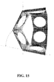
- FIG. 15 shows a drawing illustrating a Sarrus linkage that can be incorporated with an embodiment of the invention.
- FIG. 16 shows a drawing of a compliant mechanism approach for an adjustable prosthesis in accordance with an embodiment.
- FIG. 17 shows a solid model of an adjustable length prosthesis.
- FIG. 18 shows a lock-collar mechanism for an adjustable prosthesis.
- FIG. 19 shows an assembled adjustable middle ear prosthesis utilizing the lock-collar mechanism of FIG. 18 .
- FIG. 20 shows a drawing for illustrating a technique of supplying voltage to a prosthesis.
- FIG. 21 shows a graph of sliding force vs. normal force.
- FIG. 22 shows the difference in radius of the clamp and outer radius of the inner cylinder.
- FIG. 23 shows beam deflection for a cantilever beam of length/with a fixed end and a force applied at the other end.
- FIG. 24 shows the geometry of a clamp using the assumption of small angular deflection.
- FIG. 25 shows an experimental static analysis
- FIG. 26 shows a middle ear prosthesis having a clamp on an inner cylinder, according to an embodiment of the subject invention.
- FIG. 27 shows a combination of magnets on a clamp having four clamping elements according to an embodiment of the present invention.
- FIG. 28 shows permanent magnets on the edge of the cone of the inner cylinder according to an embodiment of the present invention.
- FIG. 29 shows a screw drive mechanism with threading on the outer and inner cylinders according to an embodiment of the present invention.
- FIG. 30 shows an expandable lattice
- FIG. 31 shows multiple nested sliding cylinders according to an embodiment of the present invention.
- FIG. 32 shows pressurized fluid and a ratcheted setup according to an embodiment of the present invention.
- FIG. 33 shows additional magnets on the malleus head which will balance the net force on the prosthesis without the need of external support.
- Embodiments of the present invention provide a middle ear prosthesis that can be adjusted in situ.
- Embodiments of the invention also relate to a method for adjusting a middle ear prosthesis in situ.
- the middle ear prosthesis can be inserted into the middle ear of a patient during surgery and then, after the surgery, the length of, or distance between the ends of the prosthesis can be adjusted without the need to touch the prosthesis.
- the ends of the prosthesis can rest on the malleus and the staples respectively.
- a middle ear prosthesis can include a first element 1 having a first interconnecting end and a first distal end, and a second element 5 having a second interconnecting end and a second distal end, where the first and second interconnecting ends interconnect with each other.
- the first element can incorporate an outer cylinder with a broad, optionally circular or elliptical shaped head 9 at the first distal end, for contacting the malleus or tympanic membrane
- the second element can incorporate an inner cylinder with an approximately conical foot 11 at the second distal end for contacting the stapes capitulum or footplate.
- head 9 can be approximately cylindrical.
- the head 9 of the outer cylinder can rest on the malleus, other bone of the middle ear, or eardrum, and the foot 11 of the inner cylinder can rest on the stapes (as shown in FIG. 14B ) or other bone of the middle ear.
- the inner cylinder can be inserted into the outer cylinder and inhibited from sliding by a clamp 15 with a compliant portion 17 . External forces can be applied to the clamp 15 to actuate movement of the clamp 15 and allow for adjustment of the length of the prosthesis in situ.
- a middle ear prosthesis can have a first element 1 and second element 5 , which are slidably connected to each other.
- the embodiment shown in FIGS. 1 and 2 slidably connect in a telescoping manner.
- the embodiment shown in FIG. 1 incorporated a first interconnecting end and a second interconnecting end that connected in a telescoping manner.
- the first element can have an outer cylinder 4 with an approximately cylindrical head 9 and an inner cylinder 2 with an approximately conical foot 11 .
- the head 9 can be broad and flat, and in a further specific embodiment can have a substantially elliptical transverse cross-section.
- the head 9 can have other shapes such as elliptical.
- the head 9 of the outer cylinder can rest on the malleus or tympanic membrane and the foot 11 of the inner cylinder can rest on the stapes capitulum or footplate.
- Examples of the outer cylinder and the inner cylinder are shown in more detail in FIGS. 3 and 5 , respectively. Though dimensions are listed in FIGS. 2-5 , these are only for one specific embodiment, and embodiments of the present invention are not limited thereto.
- the outer cylinder can have the approximately conical foot 11 and the inner cylinder can have the approximately cylindrical head 9 .
- circular cross-sections are shown in FIGS. 1-5 for the interconnecting ends of the first and second elements, other cross-sectional shapes can be utilized. Examples of other cross-sectional shapes that can be used for the interconnecting ends of the first and second elements include square, rectangular, hexagonal, polygonal, or other irregular shapes.
- the approximately circular or elliptical head 9 of the outer cylinder can have one or more apertures 13 , as shown in the Figures.
- the apertures can enhance the attachment of the circular head 9 to the malleus bone, or other middle bone, via scar tissue.
- the head 9 of the outer cylinder can have four apertures 13 equally spaced radially around the head (as shown in FIG. 3 ).
- the head 9 of the outer cylinder can have more or less than four apertures 13 or can have no apertures 13 at all.
- the head 9 of the outer cylinder can be a circular rim connected to the outer cylinder 4 by radial spokes as shown in FIG. 17 .
- the second interconnecting end 7 of the second element 5 can be inserted into the first interconnecting end 3 of the first element 1 .
- the inner cylinder 2 can be inserted into the outer cylinder 4
- the middle ear prosthesis can have a clamp 15 to hold the inner cylinder in place with respect to the outer cylinder or allow the inner cylinder to slide longitudinally into or out of the outer cylinder.
- the clamp 15 can be connected to either the inner cylinder or the outer cylinder.
- a compliant portion 17 of the clamp can be affixed to, and/or integrated with, the outer cylinder such that the compliant part 17 pushes the clamp 15 against the inner cylinder when the inner cylinder is inserted into the outer cylinder and the compliant part is released such that the clamp head 18 contacts the inner cylinder and the complaint part 17 holds the clamp head against the outer surface of the inner cylinder.
- the compliant portion 17 can bend, thereby allowing the inner cylinder to slide longitudinally further into or out of the outer cylinder.
- the compliant part 17 will not bend as far as FIG. 7 shows in which the bending displacement is exaggerated for visual clarity.
- the radial length and width of the clamps need not be the dimensions used to illustrate in FIGS. 33 and 9 for example.
- the value of the force required to bend the compliant beam can be dependent on the radial length of the clamp.
- the clamp 15 can be affixed to, or integrated with, the inner cylinder and can grip the outer cylinder.
- the compliant part 17 for a clamp positioned on the inner cylinder can function as described above for embodiments in which the clamp 15 is affixed to, or integrated with, the outer cylinder.
- having the clamp position on the inner cylinder can restrict the range of change in length possible as the outer cylinder can run into the clamp and/or pull far enough away to be out of range of the clamp 18 , unless a portion of the outer cylinder is cut away to allow the clamp to pass through the outer cylinder.
- the clamp 15 can incorporate one or more clamp elements, or pieces, with a clamp head 18 to inhibit unwanted sliding between the cylinders.
- the clamp 15 has at least two clamp heads 18 with associated compliant parts 17 .
- the clamp 15 has exactly two clamp heads 18 on opposite sides (radially) of the inner cylinder.
- the clamp heads are positioned such that a net-zero torque is applied to the interconnecting end of the second element to reduce binding between the interconnecting ends.
- the clamp heads can be positioned symmetrically around the first interconnecting end.
- Each clamp head can have a distal end that can contact the inner cylinder and a proximal end away from the inner cylinder (as shown in FIG. 7 ) that is affixed to, or integrated with, the compliant part 17 .
- the diameter of the inner surface of the clamp can be slightly smaller (on the order of 0.001 mm as shown in FIG. 4 which shows the radial difference as 0.0005 mm), on at least a portion of the clamp head, than the outer diameter of the inner cylinder and the inner diameter of the outer cylinder. In an embodiment, this difference in diameter can be less than 0.002 mm. In a further embodiment, this diameter is less than 0.001 mm.
- this difference can be in the range 0.0005 mm to 0.001 mm, and in another embodiment, this difference in diameter can be less than 0.0005 mm. This will result in the clamping of the inner cylinder when the clamp is released so as to be in the equilibrium position, where when in the equilibrium position, the compliant part applies a force to push the clamp head into the inner cylinder.
- the clamp head can have a variety of shapes that the compliant part causes at least a portion of the clamp head into contact with the outer surface of the interconnecting end of the second element, such as an outer surface of an inner cylinder, in order to create enough friction to hold the first element and second element in place with respect to each other.
- the radius of curvature of the clamp head is the same as the radius of curvature of the outer surface of the inner cylinder when the clamp head contacts the inner cylinder, so as to create a large amount of surface area contact between the clamp head and the inner cylinder.
- the clamp head has a radius of curvature, form by boring into the first piece, which is larger than the radius of curvature of the outer surface of the inner circle, where both are circular-shaped radius of curvatures.
- the small size of the prosthesis poses a challenge for the manufacturing process.
- the design of the embodiment shown in FIG. 1 allows for an efficient manufacturing process.
- the outer cylinder and the clamps can be manufactured from a single solid piece of material with the clamps being created by cutting twice through this single piece and the outer cylinder created by drilling into the piece.
- the clamp is integral with the outer cylinder of the first element.
- the breadth of the compliant part can be equal to the breadth of the clamp or can have a different breadth. Having the same breadth can help in separating the compliant beam from the clamps by just cutting along the length of the clamps. Then a second cut can be made across the piece to obtain the two separate clamp heads (as shown in FIG. 11 ).
- the piece can then be drilled to make a bore hole throughout the clamp head with the diameter of the hole equal to the diameter of the inner surface of the clamp.
- the clamp heads can then be pulled out of the way and a bore drilled into the outer cylinder portion of the single piece.
- the inner diameter of the outer cylinder is then drilled slightly larger than the diameter of the diameter of the inner surface of the clamp, so that the inner diameter of the outer cylinder is larger than the outer diameter of the inner cylinder and the inner diameter of the distal ends of the clamp heads is smaller than the other diameter of the inner cylinder.
- the clamps can be bent out of the way by applying a force on the ends of the compliant parts and then the required inner diameter of the outer cylinder can be obtained by boring through just the outer cylinder.
- Another set of manufacturing steps can also be used to fabricate embodiments of the present invention where the limitations are those of the manufacturer's access to the state-of-the-art fabrication techniques and processes.
- One of the most important properties for a middle ear prosthesis is the ability to avoid any microbial growth. It has been observed by surgeons that if there is any gap between the components of a prosthesis, it may result in microbial growth, possibly leading to a clinical infection (i.e., manifest by pain, effusion, and extrusion).
- the tolerances for the gap between the components is preferably less than or equal to 1 micron, including the gap between the inner diameter of the outer cylinder and the outer diameter of the inner cylinder.
- an embodiment of the present invention can include a hermetically-sealed casing 19 around the clamp, as shown in FIG. 8 .
- the seal can be fixed to the outer cylinder and completely cover both the clamps.
- the seal can either be tightly wrapped to the inner cylinder but allow sliding of the inner cylinder or can be fixed to the inner cylinder and not allow any relative motion.
- the seal is fixed to the inner cylinder, it can be made of a flexible material that allows sliding of the inner cylinder into and out of the outer cylinder and thereby allow a change in the length of the prosthesis.
- the hermetically-sealed casing can be made of any suitable material known in the art, e.g., silicon rubber, epoxy resin, and advanced ceramic materials, and can have any suitable shape.
- the hermetically-sealed casing 19 can be approximately flat in a direction facing the foot of the inner cylinder and can extend parallel to the longitudinal axis of the cylinders and then taper down toward the outer cylinder.
- the parts can be textured in such a pattern as to inhibit bacteria growth or be coated with an antimicrobial material.
- the surfaces have an antimicrobial texture.
- the surfaces are coated with an antimicrobial material.
- the prosthesis can be made from any suitable material known in the art, such as titanium for the first and second contact ends, inner and outer cylinders and clamps, with a material that creates a force on the compliant part when exposed to a magnetic field positioned on the prosthesis.
- Titanium is one of most suitable materials for medical implants because of its biocompatibility and good material properties. It is corrosion resistant, has little effect on tissue morphology and does not produce any clinical conditions. Also, the hearing range of the human ear is 40-2000 Hz, which is approximately nine octaves. Tests have demonstrated that the mass of the implant will affect the optimum transmission frequency, with the lightest mass performing best. Titanium implants are light implants and thus produce good vibration transmission. Titanium implants also have good vibration properties (for proper sound transmission) and a high yield strength value in the order of 1200 MPa, thus, making titanium an ideal choice for the material.
- Embodiments of the subject middle ear prosthesis are in the range of 2 mm to 7.5 mm (2 to 4.5 mm for PORPs and 3 to 7.5 mm for TORPs).
- the size of the prosthesis can be varied when the inner cylinder is extended from the fully contracted state (when it is completely inside the outer cylinder) to the fully expanded state (when completely outside the outer cylinder).
- the size of the prosthesis can only be doubled (approximately).
- each prosthesis should be able to be adjusted to be longer or shorter by as much as 0.5 mm.
- the first embodiment for the PORP can have a size varying from 1.8 to 2.9 mm, where 1.8 mm is the length of the unextended prosthesis and 2.9 mm is the length of the extended prosthesis.
- the second embodiment for a PORP can have a size varying from 1.9 to 3.1 mm
- the third embodiment for the PORP can have a size varying from 2.1 to 3.5 mm
- the fourth embodiment for PORP can have a size varying from 2.5 to 4.3 mm.
- the first embodiment for the TORP can have a size varying from 3.3 to 4.8 mm
- the second embodiment for the TORP can have a size varying from 3.8 to 5.8 mm
- the third embodiment for PORP can have a size varying from 4.8 to 7.8 mm.
- the outer cylinder can have a length of from about 1.41 mm to about 2.11 mm. In a further embodiment, the outer cylinder can have a length of from about 1.81 mm to about 3.31 mm. In yet a further embodiment, the outer cylinder can have a length of from about 1.51 mm to about 4.3 mm. In yet a further embodiment, the outer cylinder can have a length of about 1.71 mm. In yet a further embodiment, the outer cylinder can have a length of about 2.31 mm.
- the inner cylinder can have a length of from about 1.7 mm to about 2.4 mm. In a further embodiment, the inner cylinder can have a length of from 3.2 mm to about 4.7 mm. In yet a further embodiment, the inner cylinder can have a length of about 1.8 mm. In yet a further embodiment, the inner cylinder can have a length of about 2.0 mm. In yet a further embodiment, the inner cylinder can have a length of about 3.7 mm. In an embodiment, the length from the distal end of one clamp piece to the distal end of the opposite clamp piece can be from about 0.7. In a further embodiment, the length from the distal end of one clamp piece to the distal end of the opposite clamp piece can be about 2.3. In yet a further embodiment, the length from the distal end of one clamp piece to the distal end of the opposite clamp piece in addition to the thickness of the casing can be about 0.74 mm.
- the side-view thickness of the approximately circular head 9 of the outer cylinder can be less than about 0.1 mm. In a further embodiment, the side-view thickness of the approximately circular head 9 of the outer cylinder can be less than about 1 mm. In yet a further embodiment, the side-view thickness of the approximately circular head 9 of the outer cylinder can be less than about 0.2 mm. In yet a further embodiment, the side-view thickness of the approximately circular head 9 of the outer cylinder can be about 0.1 mm.
- the side-view thickness of the approximately conical foot 11 of the inner cylinder can be less than about 0.3 mm. In a further embodiment, the side-view thickness of the approximately conical foot 11 of the inner cylinder can be less than about 0.5 mm. In yet a further embodiment, the side-view thickness of the approximately conical foot 11 of the inner cylinder can be about 0.38 mm. In an embodiment, the diameter of the approximately circular head 9 of the outer cylinder can be less from about 3 mm to about 5 mm. In a further embodiment, the diameter of the approximately circular head 9 of the outer cylinder can be less from about 1 mm to about 4 mm. In yet a further embodiment, the diameter of the approximately circular head 9 of the outer cylinder can be 3 mm.
- the diameter of the approximately conical foot 11 of the inner cylinder can be less from about 0.6 mm to about 1.5 mm. In a further embodiment, the diameter of the approximately conical foot 11 of the inner cylinder from about 1 mm to about 2 mm. In yet a further embodiment, the diameter of the approximately conical foot 11 of the inner cylinder can be 1.2 mm.
- the middle ear prosthesis can be adjusted after placement in the middle ear, by causing the clamp 15 to bend in situ, without the need for surgery to first remove the prosthesis in order to have direct contact with the clamp 15 .
- a force can be applied to the distal ends of the clamp pieces to make the compliant portion 17 of the clamp 15 bend, thereby allowing the inner cylinder to slide longitudinally.
- the distal end of each clamp piece can have a magnetic material and/or a magnet, and an external magnetic field can be applied to cause the clamp 15 to bend.
- the magnetic field can be applied by, for example, an electromagnet outside the ear.
- the magnitude of the forces can be controlled by controlling the voltage applied on the electromagnet.
- the magnetic material and/or magnets can be positioned on the clamp such that when a magnetic field is applied the magnetic field creates a force on the clamp so as to pull the clamp away from the inner cylinder such that the inner cylinder can slide with respect to the outer cylinder.
- the magnetic material and/or magnet can be positioned along the compliant parts 17 , and preferably the distal end of the compliant part 17 to create the maximum torques and/or on the clamp head 18 , preferably at the proximal end on the portion prior to the end of the first cut such that the force tends to pull the clamp head away from the inner cylinder rather than push the clamp head toward the inner cylinder.
- a support can be provided at the end of the electromagnet that can be placed against the eardrum. The support can impede the displacement of the whole device such that the compliant part bends without transformation of the entire prosthesis, as shown in FIGS. 14B-14C .
- An alternate method of force activation could be via an embodiment with an induction coil behind the ear. The induction coil can be driven to produce a magnet field to actuate the clamp.
- Embodiments of the subject prosthesis can have the length of the prosthesis adjusted by actions of a caregiver and apparatus external to the middle ear, while the prosthesis is in situ in the middle ear. This means that if, after the patient has healed from the initial surgery of implanting the prosthesis, the patient finds that due to post-surgical variations occurring within the middle ear the initial prosthesis length is no longer correct the length of the prosthesis can be adjusted without additional surgery.
- a physician can make in situ length adjustments of the prosthesis as needed. That is, the physician can have the ability to fine tune the prosthesis to correct and improve a patient's hearing without additional surgeries.
- the in situ length adjustment can be made without insertion of tools into the middle ear.
- externally adjustable prosthesis The benefits of externally adjustable prosthesis are multi-fold: first, it minimizes risk involved in any additional surgeries. Secondly, it will improve physician's efficiency by decreasing time spent with each patient. Another benefit is that by having a prosthesis that can be both shortened and lengthened the prosthesis may not need to be discarded if it is too short.
- the following steps can be followed during the first operation to insert the prosthesis in the patient.
- the patient's ear is opened up and the prosthesis of the appropriate size is inserted and positioned onto the malleus and stapes.
- the electromagnet and the support are placed against the eardrum.
- the electromagnet is magnetized by slowly increasing the voltage supplied.
- the angular deflection of the clamp will reach the required value for release (the value of this voltage [v 0 ] can be noted for future readjustment).
- the voltage supplied is maintained at this value and the inner cylinder is manually slid using tweezers to get the desired length for the prosthesis.
- the desired length can be determined keeping in mind that the best vibration transmission is achieved by a shorter prosthesis, which results in lower tension.
- the voltage supplied to the electromagnet can then be slowly reduced to zero so that the compliant part returns to its equilibrium position and clamps the inner cylinder.
- the ear drum support and the electromagnet can then be gently removed and the ear closed up.
- the following non-invasive and external procedure can be followed for future re-adjustment of the length of the prosthesis, if and when it is required.
- the electromagnet and the support are carefully placed against the eardrum.
- the electromagnet is then magnetized by slowly increasing the voltage to the previously noted value v 0 (or to a slightly higher value).
- the magnetic forces created will release the clamps allowing the inner cylinder to slide.
- the voltage to the electromagnet is maintained at this value and the length of the prosthesis is adjusted to the required length using procedures known in the art, such as using micro tweezers to directly pull or push on the malleus or just pulling or pushing on the ear drum to cause sliding between the cylinders.
- the voltage supplied is then slowly reduced to zero so that the compliant part returns to its equilibrium position and clamps the inner cylinder.
- the electromagnet and the support are then carefully removed.
- Embodiments of the prosthesis of the present invention have been analyzed by doing stress analysis of the prosthesis using ANSYS.
- the forces involved in causing the bending of the clamps are in the order of 0.25 mN to 5 mN (depending on the radial length and width of the clamps).
- the stresses developing on the compliant part upon the application of these forces are in the order of 20 MPa, which is much less than the yield strength of the materials that can be used for the prosthesis (for e.g., Titanium).
- the pressure exerted by the circular head 9 on the malleus due to these forces will be in the order of 70 Pa. (considering a diameter of 3 mm for the circular head).
- the prosthesis is not likely to have fatigue failure. Specific embodiments can use materials to reduce the risk of injury when exposed to magnetic fields of an MRI scanner, where titanium is a material that can be used. Further embodiments of the present invention are discussed below.
- a bistable mechanism For an embodiment having clamps 15 that keep the inner cylinder from sliding, a bistable mechanism can be used.
- a bistable mechanism has two stable positions and shifts from one stable position to another upon application of a small force.
- One stable position acts as a clamp and prevents the inner cylinder from sliding.
- a second stable position allows the inner cylinder to slide.
- the magnet on the clamp Upon application of a magnetic field, the magnet on the clamp is pulled and upon the application of this force, the bistable mechanism shifts to the second stable position, thus releasing the inner cylinder.
- the length of the prosthesis can be changed. Once the desired length is obtained, the magnetic field can be reversed in polarity creating an opposing force on the magnet, and thus shifting the bistable mechanism to the first stable position so as to clamp the inner cylinder.
- a specific embodiment can have 4 clamps 15 with a permanent magnet on each clamp.
- the clamps 15 and magnets can have the orientation as shown in FIG. 27 .
- the inner cylinder is not released by a normal magnetic field because if one pair of clamps 15 is attracted by the field, the opposite pair is repelled. Rather the length can be changed by introducing a special adjusting device which has the exact opposite orientation to that of the clamps 15 . Once the clamps 15 are released, the inner cylinder is free to be adjusted.
- This example describes an approach in adjusting the length of the prosthesis without having to pull or push the ear drum (as shown in FIG. 28 ).
- Case 1 To increase the length, the polarity of the magnetic field of the electromagnet is maintained such that it is same as that of the permanent magnets on the base of the cone.
- the inner cylinder When the magnetic material is pulled resulting in the bending of the compliant part 17 , the inner cylinder is released from the clamps 15 .
- the inner cylinder is pushed farther away from the outer cylinder thus increasing the length of the prosthesis.
- Case 2 To decrease the length, the polarity of the magnetic field of the electromagnet is maintained such that it is opposite to that of the permanent magnets on the base of the cone. The attractive forces in this case will pull the inner cylinder further into to the outer cylinder thus decreasing the prosthesis length.
- the circular head 9 of the outer cylinder has permanent magnets on them with the inner cylinder fitted into the threading of the outer cylinder.
- FIG. 29 shows a threaded inner cylinder.
- the electromagnet is introduced with opposite polarity and then rotated by an angle (which depends on the change in length required and the pitch of the screw).
- the permanent magnets will rotate by the same angle, thus rotating the outer cylinder, and accordingly, changing the overall length of the prosthesis.
- magnets of different polarities can also be located to cause the inner cylinder to rotate in opposite direction and/or to maintain zero force in the longitudinal direction of the prosthesis.
- This embodiment uses a lattice structure 21 , or a pantograph-type mechanism to expand the length of the prosthesis.
- a lattice structure 21 or a pantograph-type mechanism to expand the length of the prosthesis.
- the links can fold up the range of prosthesis length is very large. Both ends can be cemented in place in the initial surgery and the lattice 21 will expand or collapse accordingly as the patient heals.
- each cylinder can be created to have its displacement dependent on the displacement of another cylinder, thus giving the prosthesis one degree of freedom.
- the benefit of this design is that one size fits all and multiple sizes will not need to be manufactured.
- the circular head 9 and the conical bell 11 are connected by a self-adjusting spring 23 .
- it is compressed and the circular head 9 and the conical bell are properly placed in position and then the spring 23 is released. It would take the best possible length depending on the length between the circular head 9 and the conical bell 11 and adjust itself in case of any change that might occur in future, thus eliminating the need of adjusting the length for the second time.
- An embodiment can use pressurized fluid 25 with a ratchet and valves, which allow a unidirectional change in length.
- pressurized fluid 25 with a ratchet and valves, which allow a unidirectional change in length.
- FIG. 32 by decreasing external pressure the fluid in the prosthesis will expand causing the inner cylinder to move outward and expand the total length of the prosthesis. Once resized and pressure is brought back to atmospheric level, the fluid will try to pull the inner cylinder back. The unidirectional teeth 27 will impede the motion of the inner cylinder back into the outer cylinder thus keeping the length stable.
- Another embodiment has a method of measuring the tensions developing in the prosthesis during the healing process or due to deformations occurring in the middle ear over a long period of time.
- This embodiment can have a structure as described for other embodiments of the subject prosthesis and can incorporate one or more piezoelectric sensors, as shown on FIG. 26 , on the head and/or the foot of the prosthesis. These sensors accurately measure the tensions acting on the prosthesis.
- the tension acting on it results in deformation of the material and thus generates voltage.
- the value of the voltage generated depends on amount of tension forces acting on the prosthesis.
- the sensor can then be connected to, for example, a resistor circuit and a coil wrapped around a rod. This results in a current i flowing through the circuit (and the coil), which would be proportional to the voltage generated and thus would be proportional to the tension developed F. i ⁇ F
- the strength of the magnetic field can be measured using a high precision magnetometer that can be placed close to the ear. From known relations, this value of B can be used to calculate the value of the tensions developed. If this calculated value is greater than the known allowable tensions on the prosthesis then the clamps have to be released to allow changes in the length of the prosthesis.
- the clamps can be released by using the same approach (of electromagnetic support) used in the other described embodiments.
- the length of the prosthesis can be changed and when a desired length is obtained the inner cylinder is clamped back. Afterward, since the tensions acting on the prosthesis would be lesser, the current i flowing through the coil and the value of B measured by the magnetometer will also be smaller. The corresponding tension can be adjusted to be less than the maximum allowable tension.
- an electromagnetic support was used to prevent the entire prosthesis from moving during application of the magnetic field by pushing on the malleus and/or the ear drum upon the application of the magnetic forces.
- This force balance can instead be obtained by using extra magnets of same polarity as the magnetic field.
- weak magnets are attached to the circular head of the outer cylinder (as shown in FIG. 33 ).
- these weak magnets are repelled by the magnetic forces (due to the same polarity) while the magnet/magnetic material on the compliant beam are attracted.
- This repulsion force can balance the net force on the prosthesis while the force on the compliant beam results in the bending of the clamps and release the inner cylinder.
- the electromagnet can be removed which results in the compliant beam returning to the equilibrium position and thus clamping the cylinder.
- the magnet on the head of the outer cylinder will be too weak to bend the compliant beam without the external field.
- a magnet can be placed at the proximal end of the compliant part such that a force equal but opposite to F 1 (see FIG. 33 ) is created at the proximal end of the compliant part (where F 1 is shown at distal end of compliant part) such that a net force of zero is exerted on the prosthesis when the magnetic field is applied to open the clamps.
- a net-zero torque is applied on the prosthesis when the prosthesis is exposed to an external magnetic field such as in the vicinity of an MRI machine.
- One embodiment uses a Sarrus linkage, as shown in FIG. 15 , to bridge the gap between the malleus and the stapes.
- One end of the Sarrus linkage can attach to the malleus while the other end attaches to the stapes.
- the malleus and stapes can be connected by a series of concatenated Sarrus linkages to reduce the radial dimensions required for a single Sarrus linkage to connect the malleus and the stapes.
- FIG. 16 Another embodiment uses a compliant mechanism internal to the outer cylindrical telescoping casing of the prosthesis, illustrated in FIG. 16 .
- This mechanism decreases the prosthetic's external length incrementally by a ratcheting type actuation. That is, the prosthesis length can be ratcheted via a physician applying pressure to the eardrum which in turn induces motion similar to the operation of a click-pen.
- the compliance (denoted by stiffness k b and k s ) within the mechanism's structure provides spring forces, that upon removal of the physicians applied force on the prosthesis via pressure on the eardrum, pulls the end of the inner rod up against mechanical stops, a feature of the contoured beams inner profile.
- This inner rod is supported by the compliant beams with stiffness (k b ).
- the outer cylinder's diameter is of the order of 1 mm or less.
- the prosthesis can be returned to its maximum length with the aid of internal springs k s and a release mechanism.
- the release mechanism can incorporate electromagnetic or mechanical means that spread radial outward the inner contoured beams slightly to allow the central rod supported by the compliant beams to pass without hooking (latching) on the mechanical stops of the contoured beams.
- a locking pin can be integrated into the prosthesis to prevent accidental ratcheting of the prosthesis length due to exposure to extreme external noise levels.
- the actuation of the prosthesis shaft can be induced by the physician pulling or pushing on the eardrum.
- the prosthesis can be a solid shaft inside of a slightly larger hollowed outer shaft or tube, illustrated in FIG. 17 .
- the inner shaft can be free to translate concentrically with respect to the outer shaft, changing the overall length.
- the active element of the prosthesis can be a locking mechanism to prevent translation after the necessary adjustments have been made, for example as shown in FIGS. 18 and 19 .
- the locking mechanism can include a collar made from bio compatible plastic that is affixed to the outer shaft. The collar can hold flexible tabs, that when closed can apply enough force to prevent motion of the inner shaft. When activated, the tabs can buckle away from the inner shaft allowing it to translate freely.
- a piezoelectric material can be used to provide a means of actuation.
- the tabs can be constructed entirely from a bio compatible piezoelectric material or made from plastic with the piezoelectric material strategically embedded within.
- an induction coil can be placed under the skin behind the patient's ear. This coil can have wires that lead to the piezoelectric elements in the prosthesis. The physician can place another coil over the embedded one behind the ear to supply the actuation voltage.
- Another version may employ a collar that is constructed completely from a piezoelectric material and affixed to the outer shaft. Application of a voltage can cause the collar to dilate freeing the inner shaft and allowing translation. While powered off, the collar can constrict the inner shaft preventing any motion.
- the outer cylinder is held stationary by a clamp 15 that is bolted into the work table.
- the inner cylinder is attached to a thin wire that hung over a metal bar to form a pulley. Attached to the other end of the wire is the bottom half of a Styrofoam cup. The inner cylinder is then manually inserted into the outer cylinder.
- the tips of two 25 GA sample syringes are hot glued to the tips of pliers cross-wise as to create a single point of contact when the pliers are closed.
- the purpose of this is to recreate the Ti—Ti friction that will be found in the actual prosthesis.
- the pliers are then fixed in place such that when closed, the glued syringe tips clamp the inner cylinder.
- the first objective was to find the force required on the inner cylinder to cause sliding. To do this, the pliers were left opened while water was added to the cup until the weight of the water overcame the friction forces of the cylinders and the inner cylinder slid out of the outer cylinder.
- the force gauge was zeroed out and the weight of the cup and water were measured five times. Furthermore, this process was repeated with four combinations of inner and outer cylinders by using two different outer cylinders and two different inner cylinders to check the consistency of the results.
- the force gauge was used to apply a force on the grips of the pliers.
- the force gauge pushed down on the grips until the tips of the pliers had minimal contact with the inner cylinder (estimated as zero contact load condition, determined via visual inspection).
- the force gauge was then zeroed out to cancel out the resulting closing force required to overcome the spring in the pliers.
- the clamping force on the inner cylinder was calculated. Similar to the previous procedure, water was added to the cup until sliding occurred. The weight of the cup and water was then measured. Also, as in the previous procedure, the weight of the cup and water was measured five times and the process was repeated with four combinations of inner and outer cylinders.
- the force being exerted by the force transducer F 1 is not the actual force acting on the inner cylinder.
- To calculate the actual clamping force F 2 the distance between the point of application of force (by the transducer) and the pliers' center of rotation r 1 and the distance between the clamping end and the same center r 2 have to be calculated.
- the ratio of the forces would be equal to the ratio of these distances (by equating the moment).
- F 1 r 1 F 2 r 2
- F 2 ( r 1 /r 2 ) F 1
- the ratio of r 1 to r 2 for the pliers was measured to be 4.
- the actual clamping force will be 4 times the force applied using the force transducer.
- Average coefficient of friction was calculated by plotting the normal forces F 2 (actual clamping force on the inner cylinder) v/s the sliding forces and obtaining the slope of the linear fit for the plot.
- the coefficient of friction is calculated as 0.21.
- the y-intercept should represent the constant friction force between the inner and outer cylinders.
- the expected value of sliding force for no clamping greatly exceeds the experimental results. This could be due to the fact that when there is no clamping the two cylinders are only slightly touching and frictional forces are minimal.
- the clamp 15 is not perfectly aligned then it could cause the inner cylinder to push up against the outer cylinder and create much greater frictional forces.
- the results demonstrate the variability that can occur within the operation of the prosthesis.
- the results provide a nominal range of expected clamping force values for an embodiment of invention.
- the inner cylinder and the clamp 15 are machined in such a way that there is a difference in the radius of the outer surface of the inner cylinder r inner and the radius of the inner surface of the clamp r clamp .
- This dimensional difference in the radii called ⁇ r results in the bending of the compliant beam 17 creating a clamping load that prevents the inner cylinder from moving relative to the outer cylinder; therefore, fixing the length of the prosthesis.
- ⁇ r r inner ⁇ r clamp
- This dimensional difference results in a horizontal force F being applied on the compliant beam 17 and a normal force N between the contact of the clamp 15 and the inner cylinder.
- the frictional force that is developed due to this normal force acts as the clamping force on the inner cylinder.
- N 114.58 ⁇ r where N is in Newtons and ⁇ r is in mm.
- the value of sliding force is 0.49 N. It is known from prior analysis that the applied force required of the electromagnet to bend the compliant beam 17 and thus unclamp the inner cylinder is in the order of 0.005 N. This 0.005 N value is much less than the above experimentally estimated minimal threshold value of 0.49 N required for sliding to occur. Thus, the experiments show that as the electromagnet creates a force on the tips of the clamping grips of the prosthesis, the clamping grips will bend and release the inner cylinder before sliding occurs.
- Embodiment 1 A method of adjusting a middle ear prosthesis in situ, comprising:
- middle ear prosthesis in a person's middle ear, wherein the middle ear prosthesis comprises:
- Embodiment 2 Embodiment 1, wherein actuating the clamp comprises exposing the actuation portion to a magnetic field having a component in the certain direction of at least the threshold value.
- Embodiment 3 Embodiment 1, wherein the first interconnecting end and the second interconnecting end are slidably connected such that when the first interconnecting end slides with respect to the second interconnecting end, the distance between the first contact end and the second contact end is adjusted.
- Embodiment 4 Embodiment 1, wherein the first interconnecting end and the second interconnecting end are connected in a telescoping manner such that when the first interconnecting end slides with respect to the second interconnecting end, the distance between the first contact end and the second contact end is adjusted.
- Embodiment 5 Embodiment 1, wherein the first interconnecting end and the second interconnecting end are rotatably connected such that when the first interconnecting end rotates with respect to the second interconnecting end, the distance between the first contact end and the second contact end is adjusted.
- Embodiment 6 Embodiment 1, wherein the first interconnecting end and the second interconnecting end are threadably connected such that when the first interconnecting end is rotated with respect to the second interconnecting end, the distance between the first contact end and the second contact end is adjusted.
- Embodiment 7 Embodiment 1, wherein the first interconnecting end comprises a bore into which the second interconnecting end is inserted.
- Embodiment 8 Embodiment 1, wherein the force tends to move the prosthesis toward the first contact end.
- Embodiment 9 Embodiment 1, wherein the clamp comprises a plurality of clamp pieces positioned symmetrically around the first interconnecting end of the first element.
- Embodiment 10 Embodiment 1, wherein the clamp comprises two clamp pieces on opposite sides of the first interconnected end.
- Embodiment 11 Embodiment 1, further comprising a hermetically-sealed casing, wherein the hermetically-sealed casing surrounds the clamp and makes a hermetic seal with the first interconnecting end and makes a hermetic seal with the second interconnecting end.
- Embodiment 12 Embodiment 1, wherein the clamp is integral with the first interconnecting end.
- Embodiment 13 Embodiment 1, wherein the clamp comprises at least one clamp head, wherein at least a portion of one or more of the at least one clamp head has a radius with respect to a longitudinal axis of the first interconnecting end smaller than a radius of an inner surface of the first interconnecting end with respect to the longitudinal axis of the first interconnecting end.
- Embodiment 14 Embodiment 1, wherein a gap between an inner surface of the first interconnecting end and an outer surface of the second interconnecting end is less than 0.002 mm.
- Embodiment 15 Embodiment 1, wherein the actuation portion comprises a magnetic material.
- Embodiment 16 Embodiment 1, wherein the actuation portion comprises a magnet.
- Embodiment 17 Embodiment 1, wherein the prosthesis further comprises a counter force portion, wherein upon exposure of the counter force portion to the magnetic field having the component in the certain direction a second force is applied to the prosthesis, wherein the second force has a component in an opposite direction to the force applied to the compliant portion.
- Embodiment 18 Embodiment 17, wherein the component of the second force has a magnitude within 5% of a magnitude of the force applied to the compliant portion.
- Embodiment 19 Embodiment 17, wherein the second force is applied to the compliant part.
- Embodiment 20 Embodiment 1, wherein the prosthesis has an unextended position where the distance between the first contact end and the second contact end is a minimum distance and an extended position where the distance between the first contact end and the second contact end is a maximum distance.
- Embodiment 21 Embodiment 1, wherein the minimum distance is in a range from 1 mm to 8 mm and the maximum distance is in a range from 1.5 mm to 15 mm.
- Embodiment 22 Embodiment 1, wherein the prosthesis comprises titanium.
- Embodiment 23 Embodiment 1, wherein the prosthesis is made of titanium and at least one volume of a material that when exposed to a magnetic field experiences a force on the volume of the material.
- Embodiment 24 Embodiment 1, wherein the second element has a length in the range from 0.5 mm to 8 mm.
- Embodiment 25 Embodiment 1, wherein the first element has a length in the range from 0.5 mm to 8 mm.
- Embodiment 26 Embodiment 1, wherein the second contact end is approximately conically shaped, wherein the first contact end has an approximately elliptically shaped transverse cross-section.
- Embodiment 27 Embodiment 1, wherein the first interconnected end has a cylindrical transverse cross-sectional shape, wherein the second interconnected end has a cylindrical cross-sectional shape.
- Embodiment 28 Embodiment 26, wherein the first contact end has a length less than 3 mm.
- Embodiment 29 Embodiment 26, wherein the first contact end has a maximum diameter in the range of 0.1 mm to 8 mm.
- Embodiment 30 Embodiment 26, wherein the second contact end has a length less than 3 mm.
- Embodiment 31 Embodiment 26, wherein a distal end of the second contact end has a diameter in the range of 0.1 mm to 8 mm.
- Embodiment 32 Embodiment 26, where the first contact end has one more apertures therethrough from a proximal end to a distal end of the first contact end.
- Embodiment 33 Embodiment 1, wherein an antimicrobial texture is applied to an outer surface to prevent microbial growth.
- Embodiment 34 Embodiment 1, wherein an antimicrobial coating is applied to an outer surface to prevent microbial growth.
- Embodiment 35 Embodiment 33, wherein an antimicrobial texture is applied to an inner surface to prevent microbial growth.
- Embodiment 36 Embodiment 34, wherein an antimicrobial coating is applied to an inner surface to prevent microbial growth.
Abstract
Description
i∝F
B∝i
B∝F
F 1 r 1 =F 2 r 2
F 2=(r 1 /r 2)F 1
| Force required | ||
| Combination | for sliding | |
| of syringes | between cylinders | |
| R1-Y1 | 0.04 lb | 0.04 | lb |
| 0.04 lb | (0.18 | N) | |
| 0.04 lb | |||
| 0.04 lb | |||
| 0.04 lb | |||
| R1-Y2 | 0.025 lb | 0.025 | lb |
| 0.025 lb | (0.11 | N) | |
| 0.025 lb | |||
| 0.025 lb | |||
| 0.025 lb | |||
| R2-Y1 | 0.045 lb | 0.045 | lb |
| 0.045 lb | (0.20 | N) | |
| 0 045 lb | |||
| 0.045 lb | |||
| 0.045 lb | |||
| R2-Y2 | 0.025 lb | 0.025 | lb |
| 0.025 lb | (0.11 | N) | |
| 0.025 lb | |||
| 0.025 lb | |||
| 0.025 lb | |||
| Average force for sliding = 0.15 N | |||
2. Telescopic Cylinders with Clamping Loads Applied to the Inner Cylinder
| Calculated | |||
| Measured force | clamping force | Measured force | |
| Combination | exerted by the | on the inner | required for sliding |
| of syringes | transducer F1 | cylinder F2 | between cylinders |
| R2-Y1 | 0.11 lb (0.49 N) | 0.11 lb (1.96 N) | 0.13 lb | 0.13 | lb |
| 0.13 lb | (0.58 | N) | |||
| 0.13 lb | |||||
| 0.13 lb | |||||
| 0.13 lb | |||||
| R2-Y2 | 0.11 lb (0.49 N) | 0.11 lb (1.96 N) | 0.13 lb | 0.13 | lb |
| 0.13 lb | (0.58 | N) | |||
| 0.13 lb | |||||
| 0.13 lb | |||||
| 0.13 lb | |||||
| Actual clamping | Force required for | ||
| Combination | Force exerted by | force on the inner | sliding between |
| of syringes | the transducer | cylinder | cylinders |
| R2-Y1 | 0.25 lb (1.11 N) | 1.00 lb (4.44 N) | 0.17 lb | 0.17 | lb |
| 0.17 lb | (0.76 | N) | |||
| 0.17 lb | |||||
| 0.17 lb | |||||
| 0.17 lb | |||||
| R2-Y2 | 0.25 lb (1.11 N) | 1.00 lb (4.44 N) | 0.15 lb | 0.15 | lb |
| 0.15 lb | (0.67 | N) | |||
| 0.15 lb | |||||
| 0.15 lb | |||||
| 0.15 lb | |||||
| Actual clamping | Force required for | ||
| Combination | Force exerted by | force on the inner | sliding between |
| of syringes | the transducer | cylinder | cylinders |
| R2-Y1 | 0.37 lb (1.65 N) | 1.47 lb (6.55 N) | 0.185 lb | 0.185 | lb |
| 0.185 lb | (0.82 | N) | |||
| 0.185 lb | |||||
| 0.185 lb | |||||
| 0.185 lb | |||||
| R2-Y2 | 0.37 lb (1.65 N) | 1.47 lb (6.55 N) | 0.185 lb | 0.185 | lb |
| 0.185 lb | (0.82 | N) | |||
| 0.185 lb | |||||
| 0.185 lb | |||||
| 0.185 lb | |||||
Δr=r inner −r clamp
Furthermore, from static analysis:
Substituting yields:
From the models for the prosthesis, the values for the known parameters are:
N=114.58Δr
where N is in Newtons and Δr is in mm.
For a value of Δr=0.0005 mm, the normal force obtained is 0.0573 N
F s=0.21N+0.48
-
- a first element, wherein the first element has a first interconnecting end and a first contact end, wherein the first contact end is adapted to contact a first location of a person's middle ear; and
- a second element, wherein the second element has a second interconnecting end and a second contact end, wherein the second contact end is adapted to contact a second location of the person's middle ear, wherein the second interconnecting end is movably connected with the first interconnecting end such that a distance between the first contact end and the second contact end can be adjusted by moving the first interconnecting end with respect to the second interconnecting end; and
- a clamp, wherein the clamp is capable of releasably securing the first interconnected end to the second interconnected end, wherein the clamp comprises at least one clamp piece positioned on the first interconnecting end, wherein each clamp piece comprises a compliant part and a clamp head, wherein the compliant part holds the clamp head against the second interconnecting end when the second interconnecting end is inserted into the first interconnecting end and the compliant part is in an equilibrium position, wherein each clamp piece comprises an actuation portion, wherein upon exposure of the actuation portion to a magnetic field having a component in a certain direction of at least a threshold value, a force is applied to the compliant portion so as to pull the head clamp away from contact with the second interconnecting end so as to allow the first interconnecting end and second interconnecting end to move with respect to each other; and
- actuating the clamp so as to allow the first interconnecting end to move with respect to the second interconnecting end;
Claims (71)
Priority Applications (1)
| Application Number | Priority Date | Filing Date | Title |
|---|---|---|---|
| US12/936,036 US8435291B2 (en) | 2008-06-20 | 2009-06-22 | Method and apparatus for in-situ adjustability of a middle ear prosthesis |
Applications Claiming Priority (3)
| Application Number | Priority Date | Filing Date | Title |
|---|---|---|---|
| US7444408P | 2008-06-20 | 2008-06-20 | |
| US12/936,036 US8435291B2 (en) | 2008-06-20 | 2009-06-22 | Method and apparatus for in-situ adjustability of a middle ear prosthesis |
| PCT/US2009/048177 WO2009155610A2 (en) | 2008-06-20 | 2009-06-22 | Method and apparatus for in-situ adjustability of a middle ear prosthesis |
Publications (2)
| Publication Number | Publication Date |
|---|---|
| US20110046731A1 US20110046731A1 (en) | 2011-02-24 |
| US8435291B2 true US8435291B2 (en) | 2013-05-07 |
Family
ID=41434732
Family Applications (1)
| Application Number | Title | Priority Date | Filing Date |
|---|---|---|---|
| US12/936,036 Expired - Fee Related US8435291B2 (en) | 2008-06-20 | 2009-06-22 | Method and apparatus for in-situ adjustability of a middle ear prosthesis |
Country Status (2)
| Country | Link |
|---|---|
| US (1) | US8435291B2 (en) |
| WO (1) | WO2009155610A2 (en) |
Cited By (3)
| Publication number | Priority date | Publication date | Assignee | Title |
|---|---|---|---|---|
| US20160081796A1 (en) * | 2014-09-24 | 2016-03-24 | The Johns Hopkins University | Removable middle ear implant sensor |
| US9743200B2 (en) | 2013-04-29 | 2017-08-22 | The Johns Hopkins University | Middle ear implant sensor |
| US10687937B2 (en) | 2016-11-08 | 2020-06-23 | Jack M. Kartush | Systems and methods for performing ossicular chain reconstructions |
Families Citing this family (8)
| Publication number | Priority date | Publication date | Assignee | Title |
|---|---|---|---|---|
| US8262729B2 (en) * | 2008-07-08 | 2012-09-11 | Enteroptyx | Dynamic ossicular prosthesis |
| US8192489B2 (en) | 2010-09-10 | 2012-06-05 | Gyrus Ent, L.L.C. | In situ adjustable ossicular implant and instrument for implanting and adjusting an adjustable ossicular implant |
| US8834567B2 (en) * | 2011-08-31 | 2014-09-16 | Mark Matthew Scheurer | Middle ear prosthesis having discrete projections for purposes of ossicular attachment |
| IL218715A (en) * | 2012-03-19 | 2014-03-31 | Mor Research Applic Ltd | Middle ear prosthesis |
| EP2803334B1 (en) * | 2013-05-17 | 2022-04-27 | Franco Beoni | Prosthetic element for connecting the stapes footplate to a middle ear ossicular prosthesis |
| AU2016235333B2 (en) * | 2015-03-20 | 2020-11-05 | Massachusetts Eye And Ear Infirmary | Artificial tympanic membrane devices and uses |
| US10646331B2 (en) * | 2017-04-26 | 2020-05-12 | University Of Maryland, Baltimore | Ossicular prosthesis and method and system for manufacturing same |
| CN114452035A (en) * | 2022-04-08 | 2022-05-10 | 杭州师范大学附属医院(杭州市第二人民医院) | Soft clip type artificial stapes prosthesis |
Citations (24)
| Publication number | Priority date | Publication date | Assignee | Title |
|---|---|---|---|---|
| US4601723A (en) | 1985-01-29 | 1986-07-22 | Mcgrew Robert N | Telescoping self-adjusting ossicular prostheses |
| US4676796A (en) | 1985-05-24 | 1987-06-30 | University Of Florida | Middle ear prosthesis |
| US4740209A (en) | 1986-01-27 | 1988-04-26 | Michel Gersdorff | Stabilizer for a middle-ear columellate prosthesis |
| US4901353A (en) | 1988-05-10 | 1990-02-13 | Minnesota Mining And Manufacturing Company | Auditory prosthesis fitting using vectors |
| US4957507A (en) | 1987-12-14 | 1990-09-18 | Edmundas Lenkauskas | Wire spring prosthesis for ossicular reconstruction |
| WO1990011737A1 (en) | 1989-04-04 | 1990-10-18 | Microtek Medical Inc. | Ossicular prosthesis |
| US5180391A (en) | 1990-06-07 | 1993-01-19 | Franco Beoni | Middle ear prosthesis |
| US6168625B1 (en) | 1998-12-01 | 2001-01-02 | Anthony D. Prescott | Adjustable length prosthesis useful for ossicular replacement and reconstruction |
| US6190305B1 (en) | 1993-07-01 | 2001-02-20 | Symphonix Devices, Inc. | Implantable and external hearing systems having a floating mass transducer |
| US20010031908A1 (en) | 1997-07-21 | 2001-10-18 | Buschek Donald J. | Hearing system with middle ear transducer mount |
| US6432139B1 (en) * | 1998-02-18 | 2002-08-13 | Spiggle & Theis | Middle ear implant |
| US20030097178A1 (en) | 2001-10-04 | 2003-05-22 | Joseph Roberson | Length-adjustable ossicular prosthesis |
| US6786860B2 (en) * | 2001-10-03 | 2004-09-07 | Advanced Bionics Corporation | Hearing aid design |
| US6942696B1 (en) | 2004-04-28 | 2005-09-13 | Clarity Corporation | Ossicular prosthesis adjusting device |
| US7025785B1 (en) | 2003-12-30 | 2006-04-11 | University Of South Florida | Incus replacement prosthesis |
| US20070055372A1 (en) | 2005-09-06 | 2007-03-08 | Prescott Anthony D | Crimp assist middle ear prosthesis |
| US7190247B2 (en) | 2002-04-01 | 2007-03-13 | Med-El Elektromedizinische Geraete Gmbh | System and method for reducing effect of magnetic fields on a magnetic transducer |
| US20070150057A1 (en) | 2004-11-12 | 2007-06-28 | Heinz Kurz | Device for adjusting the length of middle ear implants |
| US7238202B2 (en) | 2004-01-23 | 2007-07-03 | Heinz Kurz Gmbh Medizintechnik | Ossicular replacement prosthesis |
| US20070154030A1 (en) | 2006-01-04 | 2007-07-05 | Moses Ron L | Implantable hearing aid |
| US7288113B2 (en) | 2004-10-29 | 2007-10-30 | Clarity Corporation | Titanium incudo-stapedial joint prosthesis |
| US20080188707A1 (en) | 2004-11-30 | 2008-08-07 | Hans Bernard | Implantable Actuator For Hearing Aid Applications |
| US20090149697A1 (en) | 2007-08-31 | 2009-06-11 | Uwe Steinhardt | Length-variable auditory ossicle prosthesis |
| BG65712B1 (en) | 2004-12-31 | 2009-08-31 | Марио МИЛКОВ | Ossicular prosthesis and process for its manufacture |
-
2009
- 2009-06-22 US US12/936,036 patent/US8435291B2/en not_active Expired - Fee Related
- 2009-06-22 WO PCT/US2009/048177 patent/WO2009155610A2/en active Application Filing
Patent Citations (24)
| Publication number | Priority date | Publication date | Assignee | Title |
|---|---|---|---|---|
| US4601723A (en) | 1985-01-29 | 1986-07-22 | Mcgrew Robert N | Telescoping self-adjusting ossicular prostheses |
| US4676796A (en) | 1985-05-24 | 1987-06-30 | University Of Florida | Middle ear prosthesis |
| US4740209A (en) | 1986-01-27 | 1988-04-26 | Michel Gersdorff | Stabilizer for a middle-ear columellate prosthesis |
| US4957507A (en) | 1987-12-14 | 1990-09-18 | Edmundas Lenkauskas | Wire spring prosthesis for ossicular reconstruction |
| US4901353A (en) | 1988-05-10 | 1990-02-13 | Minnesota Mining And Manufacturing Company | Auditory prosthesis fitting using vectors |
| WO1990011737A1 (en) | 1989-04-04 | 1990-10-18 | Microtek Medical Inc. | Ossicular prosthesis |
| US5180391A (en) | 1990-06-07 | 1993-01-19 | Franco Beoni | Middle ear prosthesis |
| US6190305B1 (en) | 1993-07-01 | 2001-02-20 | Symphonix Devices, Inc. | Implantable and external hearing systems having a floating mass transducer |
| US20010031908A1 (en) | 1997-07-21 | 2001-10-18 | Buschek Donald J. | Hearing system with middle ear transducer mount |
| US6432139B1 (en) * | 1998-02-18 | 2002-08-13 | Spiggle & Theis | Middle ear implant |
| US6168625B1 (en) | 1998-12-01 | 2001-01-02 | Anthony D. Prescott | Adjustable length prosthesis useful for ossicular replacement and reconstruction |
| US6786860B2 (en) * | 2001-10-03 | 2004-09-07 | Advanced Bionics Corporation | Hearing aid design |
| US20030097178A1 (en) | 2001-10-04 | 2003-05-22 | Joseph Roberson | Length-adjustable ossicular prosthesis |
| US7190247B2 (en) | 2002-04-01 | 2007-03-13 | Med-El Elektromedizinische Geraete Gmbh | System and method for reducing effect of magnetic fields on a magnetic transducer |
| US7025785B1 (en) | 2003-12-30 | 2006-04-11 | University Of South Florida | Incus replacement prosthesis |
| US7238202B2 (en) | 2004-01-23 | 2007-07-03 | Heinz Kurz Gmbh Medizintechnik | Ossicular replacement prosthesis |
| US6942696B1 (en) | 2004-04-28 | 2005-09-13 | Clarity Corporation | Ossicular prosthesis adjusting device |
| US7288113B2 (en) | 2004-10-29 | 2007-10-30 | Clarity Corporation | Titanium incudo-stapedial joint prosthesis |
| US20070150057A1 (en) | 2004-11-12 | 2007-06-28 | Heinz Kurz | Device for adjusting the length of middle ear implants |
| US20080188707A1 (en) | 2004-11-30 | 2008-08-07 | Hans Bernard | Implantable Actuator For Hearing Aid Applications |
| BG65712B1 (en) | 2004-12-31 | 2009-08-31 | Марио МИЛКОВ | Ossicular prosthesis and process for its manufacture |
| US20070055372A1 (en) | 2005-09-06 | 2007-03-08 | Prescott Anthony D | Crimp assist middle ear prosthesis |
| US20070154030A1 (en) | 2006-01-04 | 2007-07-05 | Moses Ron L | Implantable hearing aid |
| US20090149697A1 (en) | 2007-08-31 | 2009-06-11 | Uwe Steinhardt | Length-variable auditory ossicle prosthesis |
Non-Patent Citations (6)
| Title |
|---|
| Dalchow, C.V., et al., "Reconstruction of the Ossicular Chain with Titanium Implants," Otolaryngology-Head and Neck Surgery, Dec. 2001, pp. 628-630, vol. 125, No. 6. |
| Fisch, U., et al., "A New L-Shaped Titanium Prosthesis for Total Reconstruction of the Ossicular Chain," Otology & Neurotology, Nov. 2004, pp. 891-902, vol. 25, No. 6. |
| Lederman, L., "Tech News: Robotics," BioTechniques, Sep. 2007, pp. 273-277, vol. 43, No. 3. |
| Lord, R.M., et al., "An Anatomically Shaped Incus Prosthesis for Reconstruction of the Ossicular Chain," Hearing Research, Jul. 2000, pp. 141-148, vol. 145, No. 1-2. |
| Zenner, H.P., et al., "Acoustomechanical Properties of Open TTP® Titanium Middle Ear Prostheses," Hearing Research, 2004, pp. 36-46, vol. 192, No. 1-2. |
| Zenner, H.P., et al., "Open Tübingen Titanium Prostheses for Ossiculoplasty: A Prospective Clinical Trial," Otology & Neurotology, Sep. 2001, pp. 582-589, vol. 22, No. 5. |
Cited By (9)
| Publication number | Priority date | Publication date | Assignee | Title |
|---|---|---|---|---|
| US9743200B2 (en) | 2013-04-29 | 2017-08-22 | The Johns Hopkins University | Middle ear implant sensor |
| US10277994B2 (en) | 2013-04-29 | 2019-04-30 | The Johns Hopkins University | Middle ear implant sensor |
| US20190215626A1 (en) * | 2013-04-29 | 2019-07-11 | The Johns Hopkins University | Middle ear implant sensor |
| US10805745B2 (en) * | 2013-04-29 | 2020-10-13 | The Johns Hopkins University | Middle ear implant sensor |
| US20160081796A1 (en) * | 2014-09-24 | 2016-03-24 | The Johns Hopkins University | Removable middle ear implant sensor |
| US9649065B2 (en) * | 2014-09-24 | 2017-05-16 | The Johns Hopkins University | Removable middle ear implant sensor |
| US10091588B2 (en) | 2014-09-24 | 2018-10-02 | The Johns Hopkins University | Removable middle ear implant sensor |
| US10721569B2 (en) | 2014-09-24 | 2020-07-21 | The Johns Hopkins University | Removable middle ear implant sensor |
| US10687937B2 (en) | 2016-11-08 | 2020-06-23 | Jack M. Kartush | Systems and methods for performing ossicular chain reconstructions |
Also Published As
| Publication number | Publication date |
|---|---|
| WO2009155610A3 (en) | 2010-03-04 |
| US20110046731A1 (en) | 2011-02-24 |
| WO2009155610A2 (en) | 2009-12-23 |
Similar Documents
| Publication | Publication Date | Title |
|---|---|---|
| US8435291B2 (en) | Method and apparatus for in-situ adjustability of a middle ear prosthesis | |
| US9492155B2 (en) | Securing element | |
| US8142500B2 (en) | Variable-length ossicular prosthesis | |
| ES2491117T3 (en) | Variable-length passive ear ossicles prosthesis | |
| US7955386B2 (en) | Middle ear prosthesis | |
| US8241353B2 (en) | Angle indicator for ocular measurements | |
| US6726719B2 (en) | Attachment mechanism for middle ear prosthesis | |
| CN108472132B (en) | The auditory ossicle prosthesis of adjustable length with low profile elastomeric joint | |
| US20090149697A1 (en) | Length-variable auditory ossicle prosthesis | |
| JP3735573B2 (en) | Equipment for installing hearing aids | |
| CN107847254A (en) | Hone lamella with dynamic element | |
| US8262729B2 (en) | Dynamic ossicular prosthesis | |
| KR20020075869A (en) | Prosthesis for controlling the direction of flow in a duct of a living organism | |
| US20170048628A1 (en) | Laser-activatable variable-length ossicular prosthesis | |
| US20080058927A1 (en) | Ossicular Prostheses Fabricated From Shape Memory Polymers | |
| US20120197066A1 (en) | Coupling apparatus | |
| Zenner et al. | Acoustomechanical properties of open TTP® titanium middle ear prostheses | |
| US8641760B2 (en) | Ossicular prosthesis with stabilizer and method of use with intact stapes | |
| US20160100263A1 (en) | Active hearing aid implant having adjustable fixation of the actuator end piece in the middle ear | |
| RU2766413C1 (en) | Implant as a prosthesis of the auditory ossicles to replace damaged parts of the middle ear | |
| US20220151665A1 (en) | Dynamic bone plate and method of use | |
| WO2016178869A1 (en) | Tendon fixation device | |
| RU2012104563A (en) | DEVICE FOR IMPLANTATION IN THE HIP JOINT AND METHOD |
Legal Events
| Date | Code | Title | Description |
|---|---|---|---|
| AS | Assignment |
Owner name: UNIVERSITY OF FLORIDA RESEARCH FOUNDATION, INC., F Free format text: ASSIGNMENT OF ASSIGNORS INTEREST;ASSIGNORS:WIENS, GLORIA JEAN;ANTONELLI, PATRICK J;RIPPERE, TROY BENJAMIN;AND OTHERS;SIGNING DATES FROM 20090629 TO 20090701;REEL/FRAME:023661/0297 |
|
| AS | Assignment |
Owner name: UNIVERSITY OF FLORIDA RESEARCH FOUNDATION, INC., F Free format text: ASSIGNMENT OF ASSIGNORS INTEREST;ASSIGNORS:WIENS, GLORIA JEAN;ANTONELLI, PATRICK J.;RIPPERE, TROY BENJAMIN;AND OTHERS;SIGNING DATES FROM 20090629 TO 20090701;REEL/FRAME:025090/0720 |
|
| STCF | Information on status: patent grant |
Free format text: PATENTED CASE |
|
| CC | Certificate of correction | ||
| FPAY | Fee payment |
Year of fee payment: 4 |
|
| FEPP | Fee payment procedure |
Free format text: MAINTENANCE FEE REMINDER MAILED (ORIGINAL EVENT CODE: REM.); ENTITY STATUS OF PATENT OWNER: SMALL ENTITY |
|
| LAPS | Lapse for failure to pay maintenance fees |
Free format text: PATENT EXPIRED FOR FAILURE TO PAY MAINTENANCE FEES (ORIGINAL EVENT CODE: EXP.); ENTITY STATUS OF PATENT OWNER: SMALL ENTITY |
|
| STCH | Information on status: patent discontinuation |
Free format text: PATENT EXPIRED DUE TO NONPAYMENT OF MAINTENANCE FEES UNDER 37 CFR 1.362 |
|
| FP | Lapsed due to failure to pay maintenance fee |
Effective date: 20210507 |