Omron SYSMAC CS Series Operation Manual
Programmable controllers
Hide thumbs
Also See for SYSMAC CS Series:
- Instruction & reference manual (1234 pages) ,
- Operation manual (316 pages) ,
- Programming manual (303 pages)

Related Manuals for Omron SYSMAC CS Series


Summary of Contents for Omron SYSMAC CS Series
- Page 1 Cat. No. W339-E1-16 SYSMAC CS Series CS1G/H-CPU_H CS1G/H-CPU_-EV1 Programmable Controllers OPERATION MANUAL...
- Page 3 SYSMAC CS Series CS1G/H-CPU@@H, CS1G/H-CPU@@-EV1 Programmable Controllers Operation Manual Revised March 2010...
- Page 5 OMRON. No patent liability is assumed with respect to the use of the information contained herein. Moreover, because OMRON is con- stantly striving to improve its high-quality products, the information contained in this manual is subject to change without notice.
- Page 6 Unit version Example for Unit version 3.0 Lot No. 040715 0000 Ver.3.0 OMRON Corporation MADE IN JAPAN • CS1-H, CJ1-H, and CJ1M CPU Units manufactured on or before Novem- ber 4, 2003 do not have a unit version given on the CPU Unit (i.e., the location for the unit version shown above is blank).
- Page 7 Unit version Use the above display to confirm the unit version of the CPU Unit. Unit Manufacturing Information In the IO Table Window, right-click and select Unit Manufacturing informa- tion - CPU Unit. The following Unit Manufacturing information Dialog Box will be displayed.
- Page 8 Unit version Use the above display to confirm the unit version of the CPU Unit connected online. Using the Unit Version The following unit version labels are provided with the CPU Unit. Labels These labels can be attached to the front of previous CPU Units to differenti- ate between CPU Units of different unit versions.
- Page 9 Units on which a version is given (Ver. @.@) given Lot No. XXXXXX XXXX Ver. @ @ .@ Lot No. XXXXXX XXXX OMRON Corporation MADE IN JAPAN Meaning Designating individual Pre-Ver. 2.0 CS1-H CPU Units CS1H-CPU67H CPU Unit Ver. @.@ CPU Units (e.g., the...
- Page 10 Unit Versions CS Series Units Models Unit version CS1-H CPU Units CS1@-CPU@@H Unit version 4.0 Unit version 3.0 Unit version 2.0 Pre-Ver. 2.0 CS1D CPU Units Duplex-CPU Systems Unit version 1.2 CS1D-CPU@@H Unit version 1.1 Pre-Ver. 1.1 Single-CPU Systems Unit version 2.0 CS1D-CPU@@S CS1 CPU Units CS1@-CPU@@...
- Page 11 • Functions Supported for Unit Version 3.0 or Later CX-Programmer 5.0 or higher must be used to enable using the functions added for unit version 3.0. CS1-H CPU Units Function CS1@-CPU@@H Unit version 3.0 or Other unit versions later Function blocks Serial Gateway (converting FINS commands to CompoWay/F commands at the built-in serial port) Comment memory (in internal flash memory)
- Page 12 • Functions Supported for Unit Version 2.0 or Later CX-Programmer 4.0 or higher must be used to enable using the functions added for unit version 2.0. CS1-H CPU Units Function CS1-H CPU Units (CS1@-CPU@@H) Unit version 2.0 or Other unit versions later Downloading and Uploading Individual Tasks Improved Read Protection Using Passwords...
- Page 13 Unit Versions and Programming Devices The following tables show the relationship between unit versions and CX-Pro- grammer versions. Unit Versions and Programming Devices CPU Unit Functions CX-Programmer Program- ming Ver. 3.3 Ver. 4.0 Ver. 5.0 Ver. 7.0 Ver. 7.2 Console or lower or higher or higher...
- Page 14 Troubleshooting Problems with Unit Versions on the CX-Programmer Problem Cause Solution An attempt was made to down- Check the program or change load a program containing to a CPU Unit with a later unit instructions supported only by version. later unit versions or a CPU Unit to a previous unit version.
-
Page 15: Table Of Contents
TABLE OF CONTENTS PRECAUTIONS ........xxvii Intended Audience . - Page 16 TABLE OF CONTENTS SECTION 4 Operating Procedures ......269 Introduction ............. . Examples .
- Page 17 TABLE OF CONTENTS 9-15 Holding Area............. 9-16 Auxiliary Area.
- Page 18 xviii...
- Page 19 CS1G/H-CPU@@-EV1 or CS1G/H- CPU@@H CPU Units in a PLC System. Name Cat. No. Contents SYSMAC CS Series W339 Provides an outlines of and describes the CS1G/H-CPU@@H, CS1G/H-CPU@@-EV1 design, installation, maintenance, and other Programmable Controllers Operation Manual basic operations for the CS-series PLCs.
- Page 20 CS1W-SCB@@-V1, CS1W-SCU@@-V1, CJ1W-SCU@@-V1 Unit and Boards to perform serial communica- Serial Communications Boards/Units Operation Manual tions with external devices, including the usage of standard system protocols for OMRON prod- ucts. SYSMAC WS02-PSTC1-E W344 Describes the use of the CX-Protocol to cre-...
- Page 21 Section 5 describes how to install a PLC System, including mounting the various Units and wiring the System. Be sure to follow the instructions carefully. Improper installation can cause the PLC to mal- function, resulting in very dangerous situations. Section 6 describes the settings of the DIP switch and how they affect operation. Section 7 describes the settings in the PLC Setup and how they are used to control CPU Unit opera- tion.
- Page 22 xxii...
- Page 23 WHETHER SUCH CLAIM IS BASED ON CONTRACT, WARRANTY, NEGLIGENCE, OR STRICT LIABILITY. In no event shall the responsibility of OMRON for any act exceed the individual price of the product on which liability is asserted. IN NO EVENT SHALL OMRON BE RESPONSIBLE FOR WARRANTY, REPAIR, OR OTHER CLAIMS...
- Page 24 Application Considerations SUITABILITY FOR USE OMRON shall not be responsible for conformity with any standards, codes, or regulations that apply to the combination of products in the customer's application or use of the products. At the customer's request, OMRON will provide applicable third party certification documents identifying ratings and limitations of use that apply to the products.
- Page 25 Performance data given in this manual is provided as a guide for the user in determining suitability and does not constitute a warranty. It may represent the result of OMRON's test conditions, and the users must correlate it to actual application requirements. Actual performance is subject to the OMRON Warranty and Limitations of Liability.
- Page 26 xxvi...
-
Page 27: Precautions
PRECAUTIONS This section provides general precautions for using the CS-series Programmable Controllers (PLCs) and related devices. The information contained in this section is important for the safe and reliable application of Programmable Controllers. You must read this section and understand the information contained before attempting to set up or operate a PLC system. -
Page 28: Intended Audience
It is extremely important that a PLC and all PLC Units be used for the speci- fied purpose and under the specified conditions, especially in applications that can directly or indirectly affect human life. You must consult with your OMRON representative before applying a PLC System to the above-mentioned appli- cations. - Page 29 Safety Precautions !WARNING Do not touch any of the terminals or terminal blocks while the power is being supplied. Doing so may result in electric shock. !WARNING Do not attempt to disassemble, repair, or modify any Units. Any attempt to do so may result in malfunction, fire, or electric shock.
-
Page 30: Operating Environment Precautions
Operating Environment Precautions !Caution A CS1-H/CJ1-H/CJ1M/CS1D CPU Unit automatically back up the user pro- gram and parameter data to flash memory when these are written to the CPU Unit. I/O memory (including the DM, EM, and HR Areas), however, is not writ- ten to flash memory. -
Page 31: Application Precautions
Application Precautions • Locations close to power supplies. !Caution The operating environment of the PLC System can have a large effect on the longevity and reliability of the system. Improper operating environments can lead to malfunction, failure, and other unforeseeable problems with the PLC System. - Page 32 Application Precautions • Always connect to a ground of 100 Ω or less when installing the Units. Not connecting to a ground of 100 Ω or less may result in electric shock. • A ground of 100 Ω or less must be installed when shorting the GR and LG terminals on the Power Supply Unit.
- Page 33 Application Precautions output terminals on DC Output Units and other Units will momentarily turn ON when power is turned ON to the PLC. • Fail-safe measures must be taken by the customer to ensure safety in the event that outputs from Output Units remain ON as a result of internal cir- cuit failures, which can occur in relays, transistors, and other elements.
- Page 34 Application Precautions • Separate the line ground terminal (LG) from the functional ground termi- nal (GR) on the Power Supply Unit before performing withstand voltage tests or insulation resistance tests. Not doing so may result in burning. • Change the applied voltage gradually using the adjuster on the Tester. If full dielectric strength voltage is applied or turned OFF using the switch on the Tester, the generated impulse voltage may damage the Power Supply Unit.
- Page 35 Application Precautions • Never connect pin 6 (5-V power supply) on the RS-232C port on the CPU Unit to any device other than an NT-AL001, CJ1W-CIF11 Link Adapter, or NV3W-M@20L Programmable Terminal. The external device or the CPU Unit may be damaged. •...
-
Page 36: Conformance To Ec Directives
Concepts EMC Directives OMRON devices that comply with EC Directives also conform to the related EMC standards so that they can be more easily built into other devices or the overall machine. The actual products have been checked for conformity to EMC standards (see the following note). -
Page 37: Conformance To Ec Directives
Conformance to EC Directives and other conditions. You must therefore confirm that the overall machine or equipment complies with EC Directives. Relay Output Noise Reduction Methods The CS-series PLCs conforms to the Common Emission Standards (EN61000-6-4) of the EMC Directives. However, noise generated by relay out- put switching may not satisfy these Standards. - Page 38 Conformance to EC Directives Circuit Current Characteristic Required element The diode connected in parallel with the The reversed dielectric strength value Diode method load changes energy accumulated by the of the diode must be at least 10 times coil into a current, which then flows into as large as the circuit voltage value.
-
Page 39: Introduction
SECTION 1 Introduction This section introduces the special features and functions of the CS-series PLCs and describes the differences between these PLCs and other PLCs. Overview ............CS-series Features. -
Page 40: Overview
Overview Section 1-1 Overview The CS-series PLCs are medium-sized Programmable Controllers that pro- vide improved programming efficiency by dividing the program into tasks. The CS-series PLCs also feature faster processing, higher capacities, multiple ports supporting protocol macros, improved seamless communications across three network levels, and much more, enabling them to flexibly handle advanced information capabilities as core FA controllers. -
Page 41: Cs-Series Features
D32767 rather than the maximum DM address of D09999 in C200HX/HG/HE PLCs. Program Compatibility Programs from earlier OMRON PLCs (such as the C200H, C200HS, C200HX/HG/HE, and CV Series) can be imported into the CS-series PLCs. CS-series and C200H High-density CS-series Units, such as the 96-point I/O Units and 8-point Ana-... - Page 42 CS-series Features Section 1-2 Task Earlier program Task Task Task When a new program is being created, standard programs can be combined as tasks to create an entire program. Standard programs Program ABD Program ABC Task 1 (A) Task 1 (A) Task 2 (B) Task 2 (B) Task 3 (C)
- Page 43 Symbols that read and write data to the CPU Unit can be included in the com- munications frames, so data can be exchanged with the CPU Unit very easily. OMRON components (such as Temperature Controllers, ID System Devices, Bar Code Readers, and Modems) can be connected to a Serial Communica- tions Board or Serial Communications Unit with the standard system protocol.
- Page 44 CS-series Features Section 1-2 Transmit or receive data with just one instruction. External device Multilevel Network Configurations Different network levels can be connected as shown in the following diagram. The multilevel configuration provides more flexibility in networking from the manufacturing site to production management. In particular, the DeviceNet network makes it very easy to connect devices from other manufacturers.
- Page 45 CS-series Features Section 1-2 Remote Monitoring and Programming 1,2,3... 1. The host link function can operate through a modem, which allows moni- toring of a distant PLC’s operation, data transfers, or even online editing of a distant PLC’s program by phone. 2.
-
Page 46: Versatile Functions
CS-series Features Section 1-2 High-speed NT Link communications between an NS-series or NT31/NT631-V2 PT and a Communications with PTs CS-series PLC are possible at high speed (except for pre-version 1 CS1 CPU Units). 1-2-2 Versatile Functions Memory Card and File Management Functions Transfer Data to and from Data area data, program data, and PLC Setup data can be saved as files on a Memory Cards... - Page 47 CS-series Features Section 1-2 Easy Backups It is now possible to back up all data (user programs, parameters, and I/O memory) to the Memory Card by pressing the Memory Card power supply switch. In this way, if a malfunction arises, it is possible to back up all data in the CPU Unit at the time without using a Programming Device.
- Page 48 CS-series Features Section 1-2 Record-table Instructions Record-table instructions operate on specially defined data tables. The record table must be defined in advance with DIM(631), which declares the number of words in a record and the number of records in the table. Up to 16 record tables can be defined.
- Page 49 CS-series Features Section 1-2 Data Trace Function The content of the specified word or bit in I/O memory can be stored in trace memory by one of the following methods: scheduled sampling, cyclic sam- pling, or sampling at execution of TRSM(045). Trace memory Specified address in I/O memory...
- Page 50 CS-series Features Section 1-2 Windows Tools The single-port multiple-access (SPMA) function can be used to program and monitor other CPU Bus Units on the same bus (CPU Rack or Expansion racks) or other CPU Units on the same network from a serial port on the CPU Unit or a Serial Communications Board.
-
Page 51: Cs1-H Cpu Unit Features
CS1-H CPU Unit Features Section 1-3 CS1-H CPU Unit Features 1-3-1 High-speed Performance Ultra High-speed Cycle The CS1-H CPU Units provide a cycle time that is three to four times faster Time than that of the CS1 CPU Units. For example, a program consisting of 38 Ksteps of only basic instructions with 128 inputs and 128 outputs executes in 1 ms (4.2 ms for the CS1 CPU Units);... -
Page 52: High-Speed Structured Programming
ST lan- guage. OMRON function blocks can be written in ladder language or ST (structured text) language, and conform to IEC 61131-3 standards (JIS B3503). The func- tion blocks provide functions for more efficient design and debugging of the user equipment, as well as easier maintenance. -
Page 53: More Instructions For Specific Applications
4.0 or later and CX-Programmer version 7.0 or higher.) Nesting Not only can programs be created with nested OMRON FBs, it is possible to make easy-to-understand, stress-free operations by switching displays under preset conditions and displaying structures in a directory-tree format. -
Page 54: Battery-Free Operation With Flash Memory
CS1-H CPU Unit Features Section 1-3 PID Autotuning Autotuning is now supported for PID constants with the PID CONTROL instruction. The limit cycle method is used to ensure rapid autotuning. Very effective for multiloop PID control. System Debugging A specified error status can be created with the FAL/FALS instructions. This through Error Simulation can be used effectively when depending systems. -
Page 55: Changes To Cs-Series Operating Specifications
CS1-H CPU Unit Features Section 1-3 Incorporate CompoWay/F-compatible OMRON Components into FINS Network Via Serial Gateway Using the Serial Gateway mode for the CPU Unit’s serial port enables flexible access to CompoWay/F-compatible OMRON components from devices on the network (e.g., PTs, PLC CPU Units, personal computers) Store Comment/Section Data in CPU Unit’s Flash Memory... -
Page 56: Features Of Cs1-H Cpu Units Ver. 2.0
CS1-H CPU Unit Features Section 1-3 1-3-10 Features of CS1-H CPU Units Ver. 2.0 Easier System Development by Teams Download/Upload Tasks Individually with CX-Programmer Version 4.0 or Higher The CX-Programmer (version 4.0 or higher) can be used to upload or down- load only the required tasks. - Page 57 CS1-H CPU Unit Features Section 1-3 Easier Implementation of Explicit Messages with Explicit Message Instructions Special Explicit Message Instructions are now supported to simplify using explicit messages. (Previously, CMND(490) had to be used to send a FINS command of 2801 hex to enable sending explicit messages.) The new instruc- tions include the following: EXPLICIT MESSAGE SEND (EXPLT(720)), EXPLICIT GET ATTRIBUTE (EGATR(721)), EXPLICIT SET ATTRIBUTE (ESATR(722)), EXPLICIT WORD READ (ECHRD(723)), and EXPLICIT...
- Page 58 CS1-H CPU Unit Features Section 1-3 GRAY CODE CONVERSION (GRY(474)) for Easy Conversion of Parallel Inputs from Absolute Encoders to Binary, BCD, or Angle Data This instruction converts Gray binary codes to binary, BCD, or angle data. This enables easily handling position or angle data input as parallel signals ) from an Absolute Encoder with a Gray code output using a DC Input Unit.
- Page 59 CS1-H CPU Unit Features Section 1-3 Power Supply Units with Replacement Notification The C200HW-PA204C Power Supply Units with Replacement Notification pro- vide six display levels using a 7-segment display on the front panel of the Unit to indicate the remaining service life of the Power Supply Unit. An alarm out- put also notifies when the estimated remaining service life drops to 6 months or shorter.
-
Page 60: Cs1-H Cpu Unit Ver. 4.0 Upgrades
CS1-H CPU Unit Ver. 4.0 Upgrades Section 1-4 CS1-H CPU Unit Ver. 4.0 Upgrades This section summarizes the upgrades made for CS1-H CPU Units with unit version 4.0. CX-Programmer version 7.0 or higher must be used to enable using the following functions. Functional Upgrades for Unit Version 4.0 Function Section... -
Page 61: Cs1-H Cpu Unit Ver. 3.0 Upgrades
CS1-H CPU Unit Ver. 3.0 Upgrades Section 1-5 " Bl" is #426C in ASCII. #426C stBlack[0] " ac" is #6163 in ASCII. #6163 stBlack[1] Unit Version 4.0 or Later Text strings can be used in ST programming to easily create text string pro- cessing programs. -
Page 62: Function Blocks (Fb)
Function blocks can be created with CX-Programmer Ver. 5.0 or higher by the user and pasted into normal programs. The standard function blocks provided by OMRON in the OMRON FB Library can also be pasted into normal pro- grams. Function blocks enable standard processing to be simply inserted into a program as a single unit. -
Page 63: Serial Gateway (Converting Fins To Compoway/F Via Serial Port)
CompoWay/F command frames and transmitted on the serial line. This enables access to CompoWay/F-compati- ble OMRON components that are connected to the CPU Unit’s built-in serial port via either an NS-series Programmable Terminal (PT) or by using the CMND(490) instruction. -
Page 64: Comment Memory (In Internal Flash Memory)
CS1-H CPU Unit Ver. 3.0 Upgrades Section 1-5 1-5-3 Comment Memory (in Internal Flash Memory) Pre-Ver. 2.0 Comment data and section data could not be stored in the actual PLC when a project was downloaded from the CX-Programmer to the CPU Unit unless both a Memory Card and EM file memory were available. -
Page 65: Free Running Timer
CS1-H CPU Unit Ver. 3.0 Upgrades Section 1-5 • Comment files (CX-Programmer rung comments and other comments) • Program index files (CX-Programmer section names, section comments, and program comments) Simple backup executing CPU Unit • User program • Parameters • I/O memory Memory Card CS/CJ Series (In comment memory) -
Page 66: New Special Instructions And Functions
CS1-H CPU Unit Ver. 3.0 Upgrades Section 1-5 Note The timer will continue to be incremented when the operating mode is switched to RUN mode. Example: The interval can be counted between processing A and processing B without requiring timer instructions. This is achieved by calculat- ing the difference between the value in A000 for processing A and the value in A000 for processing B. - Page 67 CS1-H CPU Unit Ver. 3.0 Upgrades Section 1-5 Therefore, the increase in maximum number of points applies to all CS-series CPU Units, including those that have already been shipped. Refer to the following table for details. Item Before Maximum num- SYSMAC Bus 800 points 1,280 points...
-
Page 68: Cs1-H Cpu Unit Ver. 2.0 Upgrades
CS1-H CPU Unit Ver. 2.0 Upgrades Section 1-6 CS1-H CPU Unit Ver. 2.0 Upgrades The following table shows the functional upgrades for CS1-H CPU Unit Ver. 2.0. Functional Upgrades for CS1-H CPU Unit Ver. 2.0 Function Reference Downloading and Uploading Individual Tasks 1-6-1 Improved Read Protection Using Passwords 1-6-2... -
Page 69: Improved Read Protection Using Passwords
CS1-H CPU Unit Ver. 2.0 Upgrades Section 1-6 CPU Unit Ver. 2.0 Overview With CPU Unit Ver. 2.0 or later CPU Units, individual program tasks can be uploaded and downloaded from the CX-Programmer. CX-Programmer Individual tasks (programs) Download individual tasks (programs). CS/CJ-series CPU Unit Ver.2.0 or later Usage... - Page 70 CS1-H CPU Unit Ver. 2.0 Upgrades Section 1-6 Task read protection prevents anyone from displaying, editing, or uploading the read-protected set of tasks from CX-Programmer without inputting the cor- rect password. In this case, the entire program can be uploaded, but the read- protected tasks cannot be displayed or edited without inputting the correct password.
- Page 71 CS1-H CPU Unit Ver. 2.0 Upgrades Section 1-6 b) Setting Password Protection without Transferring the Program: Select PLC - Protection - Set Password and click the OK button. The tasks registered in step 2 will be password-protected. Usage Apply read protection to tasks when you want to convert those tasks (pro- grams) to “black box”...
- Page 72 CS1-H CPU Unit Ver. 2.0 Upgrades Section 1-6 CX-Programmer When a password is being registered for the entire user program or selected tasks, the creation of backup program files (.OBJ files) can be Password? enabled/disabled with an option setting. Online creation of backup program files (.OBJ files) prohibited by option setting.
- Page 73 CS1-H CPU Unit Ver. 2.0 Upgrades Section 1-6 CPU Unit Ver. 2.0 or Later With the CPU Unit Ver. 2.0 and later CPU Units, the CPU Unit's UM area can and CX-Programmer be write protected by turning ON pin 1 of the CPU Unit's DIP switch. The pro- Ver.
-
Page 74: Write Protection From Fins Commands Sent To Cpu Units Via Networks
CS1-H CPU Unit Ver. 2.0 Upgrades Section 1-6 Auxiliary Area Flags and Bits related to Password Protection Name Description address UM Read Protection A09900 Indicates whether or not the PLC (the entire user Flag program) is read-protected. 0: UM read protection is not set. 1: UM read protection is set. - Page 75 CS1-H CPU Unit Ver. 2.0 Upgrades Section 1-6 Example: Write operations by FINS com- Computer #1 mands are prohibited from some nodes in the network (in this exam- ple, computer #1, PLC #1, and PLC #2). Computer #2 Network PLC #2 PLC #3 PLC #1 Network...
- Page 76 CS1-H CPU Unit Ver. 2.0 Upgrades Section 1-6 Connection pattern Diagram (example) Write protection From a computer through a Can be The CPU Unit in PLC #2 direct network connection applied. can be write-protected. Computer PLC #1 PLC #2 Network From another PLC in the Can be If the CMND instruction is used to send...
- Page 77 CS1-H CPU Unit Ver. 2.0 Upgrades Section 1-6 PLC Setup Item Address in Description Settings Default setting Programming Console Use FINS Write Word 448, bit 15 Sets whether the CPU Unit is 0: Write protection 0: Write protection Protection write-protected from FINS com- disabled disabled mands sent through the network.
- Page 78 CS1-H CPU Unit Ver. 2.0 Upgrades Section 1-6 System control/monitoring computer Allowed to write/control Equipment Network Monitoring computer Controller Not allowed to Allowed to write/control write/con- trol PLC Network Network CS/CJ-series PLC Operations Restricted by FINS Write Commands Network FINS Write The following FINS commands are restricted by FINS write protection when Protection sent to the CPU Unit through the network.
-
Page 79: Online Network Connections Without I/O Tables
CS1-H CPU Unit Ver. 2.0 Upgrades Section 1-6 Operations from CX-Programmer (including CX-Net) through the Network The following CX-Programmer (including CX-Net) operations are restricted by FINS write protection when performed on the CPU Unit through the network. Operations not • Changing the Operating Mode allowed through the •... - Page 80 CS1-H CPU Unit Ver. 2.0 Upgrades Section 1-6 CPU Unit Ver. 2.0 or Later Summary With the CPU Unit Ver. 2.0 and later CS/CJ-series CPU Units, the CPU Unit can recognize a CPU Bus Unit (such as a Network Communications Unit, see note) even if the I/O tables have not been created and there is no registered I/O tables.
-
Page 81: Communications Through A Maximum Of 8 Network Levels
CS1-H CPU Unit Ver. 2.0 Upgrades Section 1-6 Note 1. A non-fatal I/O verification error will occur if a CPU Bus Unit (including a Network Communications Unit) is used without creating I/O tables. 2. With a CPU Unit Ver. 2.0 or later CS1-H CPU Unit, CPU Bus Units can be used even if the I/O tables have not been created, but the purpose of this function is making an online connection through the network with a com- puter-based Programming Device (such as the CX-Programmer). - Page 82 CS1-H CPU Unit Ver. 2.0 Upgrades Section 1-6 CPU Unit Ver. 2.0 or Later Summary With the CPU Unit Ver. 2.0 or later CS/CJ-series CPU Units, it is possible to communicate through 8 network levels max. (see note), including the local network.
- Page 83 CS1-H CPU Unit Ver. 2.0 Upgrades Section 1-6 Example: At this point, the gateway counter = 6 hex At this point, the gateway counter = 4 hex FINS command FINS command source destination Network 2 Network 4 FINS command FINS command FINS command FINS command FINS command...
-
Page 84: Connecting Online To Plcs Via Ns-Series Pts
CS1-H CPU Unit Ver. 2.0 Upgrades Section 1-6 1-6-6 Connecting Online to PLCs via NS-series PTs Summary The CX-Programmer can be connected online to a PLC connected via a serial line to an NS-series PT that is connected to the CX-Programmer via Ethernet (see note 2). -
Page 85: Setting First Slot Words
CS1-H CPU Unit Ver. 2.0 Upgrades Section 1-6 1-6-7 Setting First Slot Words Previous CPU Units (Pre-Ver. 2.0 CPU Units) With CX-Programmer Ver. 3.0 or earlier, only the first addresses on Racks could be set. The first address for a slot could not be set. First addresses on Racks Example: First address... - Page 86 CS1-H CPU Unit Ver. 2.0 Upgrades Section 1-6 Operating Procedure Select Option - Rack/Slot Start Addresses in the PLC IO Table - Traffic Con- troller Window. This command will enable setting both the first Rack addresses and the first slot addresses. Select Option - Rack/Slot Start.
-
Page 87: Automatic Transfers At Power On Without A Parameter File
CS1-H CPU Unit Ver. 2.0 Upgrades Section 1-6 CPU Unit Ver. 2.0 or Later and CX-Programmer Ver. 4.0 or Higher Summary When using CX-Programmer Ver.4.0 or higher with CPU Unit Ver. 2.0 or later, the first address can be set for up to 64 slots. Note This function is supported only for CS1-H, CJ1-H, and CJ1M CPU Units Ver. - Page 88 CS1-H CPU Unit Ver. 2.0 Upgrades Section 1-6 Even if a program file (.OBJ) was created offline without the actual PLC and then sent to a remote PLC as an email attachment, the program file could not be transferred to the CPU Unit without a Programming Device. Personal Local site (no Programming Device) computer...
-
Page 89: Operation Start/End Times
CS1-H CPU Unit Ver. 2.0 Upgrades Section 1-6 1-6-9 Operation Start/End Times Previous CPU Units (Pre-Ver. 2.0 CPU Units) The time that operation started and the time operation ended were not stored in the CPU Unit. CPU Unit Ver. 2.0 or Later The times that operation started and ended are automatically stored in the Auxiliary Area. -
Page 90: Cs1 And Cs1-H Cpu Unit Comparison
CS1 and CS1-H CPU Unit Comparison Section 1-7 CS1 and CS1-H CPU Unit Comparison 1-7-1 CS1 and CS1-H CPU Unit Comparison Item CS1-H CPU Unit CS1 CPU Unit (CS1H-CPU6@H, CS1G-CPU4@H) (CS1H-CPU6@-E, CS1G-CPU4@-E) LD: 0.02 µs 0.04 µs Instruction Basic instructions executions OUT: 0.02 µs 0.17 µs... - Page 91 CS1 and CS1-H CPU Unit Comparison Section 1-7 Item CS1-H CPU Unit CS1 CPU Unit (CS1H-CPU6@H, CS1G-CPU4@H) (CS1H-CPU6@-E, CS1G-CPU4@-E) Tasks Cyclic execution of interrupt Supported Not supported tasks via TKON instruction (Up to 255 extra cyclic tasks, (No extra cyclic tasks; 32 cyclic tasks (called “extra cyclic tasks”) increasing the total number of max.)
- Page 92 CS1 and CS1-H CPU Unit Comparison Section 1-7 Item CS1-H CPU Unit CS1 CPU Unit (CS1H-CPU6@H, CS1G-CPU4@H) (CS1H-CPU6@-E, CS1G-CPU4@-E) Sequence Differentiated LD NOT, AND Supported Not supported (Can be programmed instructions NOT, and OR NOT instruc- by combining differentiated LD, AND, tions and OR instructions with the NOT instruction.)
- Page 93 CS1 and CS1-H CPU Unit Comparison Section 1-7 Item CS1-H CPU Unit CS1 CPU Unit (CS1H-CPU6@H, CS1G-CPU4@H) (CS1H-CPU6@-E, CS1G-CPU4@-E) Index regis- Program and real I/O memory CVM1/CV-series real I/O memory Not supported ter real I/O address compatibility with addresses can be converted to CS- address con- CVM1/CV-series PLCs series addresses and placed in...
-
Page 94: New Functions For Version-1 Cs1 Cpu Units
CS1 and CS1-H CPU Unit Comparison Section 1-7 1-7-2 New Functions for Version-1 CS1 CPU Units The following functions have been added or improved in the version-1 CS1 CPU Units (CS1G/H-CPU@@-EV1; previous version: CS1G/H-CPU@@-E). Item Function Application Reference Support for CSV and The FREAD/FWRIT instructions can Production results from I/O memory in Section 5 File... -
Page 95: Cs-Series Function Tables
CS-series Function Tables Section 1-8 CS-series Function Tables The following tables list functions for the CS-series CPU Units (including both the CS1 CPU Units and the CS1-H CPU Units). 1-8-1 Functions Arranged by Purpose Purpose Function Reference SECTION 2 Spec- Studying Basic Studying the system configuration ifications and Sys-... - Page 96 CS-series Function Tables Section 1-8 Purpose Function Reference Managing the Reducing the cycle time. • Use tasks to put parts of the pro- Programming Cycle Time gram that don’t need to be exe- Manual (W394) cuted into “standby” status. • Use JMP(004) and JME(005) to jump parts of the task that don’t need to be executed.
- Page 97 CS-series Function Tables Section 1-8 Purpose Function Reference Data Process- Operating a FIFO or LIFO stack. Use the stack instructions Instructions Refer- (FIFO(633) and LIFO(634)). ence Manual (W340) Performing basic operations on Use range instructions such as tables made up of 1-word records. MAX(182), MIN(183), and SRCH(181).
- Page 98 CS-series Function Tables Section 1-8 Purpose Function Reference Controlling Maintaining the previous contents of Turn ON the IOM Hold BIt (A50012). Programming I/O Memory all I/O Memory at the start of PLC Manual (W394) operation (hot start). Maintaining the previous contents of Turn ON the IOM Hold BIt (A50012) all I/O Memory when the PLC is and set the PLC Setup to maintain...
- Page 99 CS-series Function Tables Section 1-8 Purpose Function Reference Maintenance Changing the program while it is Use the online editing function from Programming and Debugging being executed. a Programming Device. Manual (W394) (Several instruction blocks can be changed with CX-Programmer.) Sampling I/O Memory data. •...
-
Page 100: Communications Functions (Serial/Network)
CS-series Function Tables Section 1-8 Purpose Function Reference Reducing input chattering and the Specify the input response times for effects of noise. Basic I/O Units in the PLC Setup. (Basic I/O Unit Input Response Time) 8-4 Allocating Allocating words in the I/O Area Set the first word allocated to a slot First Words to freely by specifying the word allo-... - Page 101 CS-series Function Tables Section 1-8 Purpose Protocol: Required Equipment Reference 2-5-3 Com- Message Control system Controller Link: munications communications Controller Link Unit or Controller Link Network Sys- between PLC Board and computer Information system Ethernet: Ethernet Unit Remote I/O High-density I/O DeviceNet: between PLC DeviceNet Master Unit and required...
-
Page 102: Cs1-H Functions Arranged By Purpose
CS1-H Functions Arranged by Purpose Section 1-9 CS1-H Functions Arranged by Purpose Purpose Function Increas- Reducing the cycle time and improving Use the Parallel Processing Mode with Synchronous Memory communications responsiveness. Access or Parallel Processing Mode with Asynchronous Mem- speed ory Access. - Page 103 CS1-H Functions Arranged by Purpose Section 1-9 Purpose Function Increas- Using more tasks Define interrupt tasks as cyclic tasks (called “extra cyclic tasks”). structure Reducing the cycle time even with structured Use shared index and data registers. programs using many tasks Using the same index or data registers in dif- ferent tasks without saving and loading regis- ter contents...
-
Page 104: Comparison Of Cs-Series Plcs And C200Hx/Hg/He Operation
Comparison of CS-series PLCs and C200HX/HG/HE Operation Section 1-10 Purpose Function Debug- Simulating errors in the CPU Unit when Use FAL/FALS to simulate fatal and nonfatal system errors. ging and debugging the system, e.g., to check error mainte- messages displayed on a PT nance Backing up CPU Unit data and internal from Use the simple backup operation, which includes data from... - Page 105 Comparison of CS-series PLCs and C200HX/HG/HE Operation Section 1-10 Item C200HX/HG/HE PLCs CS-series PLCs Data Areas CIO I/O Area IR 000 to IR 029, CIO 0000 to CIO 0319 (CIO 0000 to CIO 0999 Area IR 300 to IR 309 can be set if the first word on the Rack is set.) (Unlike the CS Series, word alloca- (Unlike the C200HX/HG/HE PLCs, word alloca-...
- Page 106 Comparison of CS-series PLCs and C200HX/HG/HE Operation Section 1-10 Item C200HX/HG/HE PLCs CS-series PLCs Data EM Area EM 0000 to EM 6143 E00000 to E32767 Areas, (3 banks max., 16 banks max. for (13 banks max.) continued ZE-version PLCs) Regular instructions can access data in the cur- Basically, those EM Area instruc- rent bank or any other bank.
-
Page 107: Comparison Of Cs-Series Plcs And C200Hx/Hg/He Operation
Comparison of CS-series PLCs and C200HX/HG/HE Operation Section 1-10 Item C200HX/HG/HE PLCs CS-series PLCs Instructions Sequence Input Up and down-differentiated ver- Up and down-differentiated versions of LD, AND, sions of LD, AND, and OR are not and OR are supported. supported. - Page 108 Comparison of CS-series PLCs and C200HX/HG/HE Operation Section 1-10 Item C200HX/HG/HE PLCs CS-series PLCs Instruc- Step The same in both series, although the specified control bit must be in the WR Area in tions, con- CS-series PLCs. tinued I/O Units TKY, HKY, DSW, and CMCR TKY, HKY, DSW, and CMCR not supported.
- Page 109 Comparison of CS-series PLCs and C200HX/HG/HE Operation Section 1-10 Item C200HX/HG/HE PLCs CS-series PLCs Memory User program The entire program can be saved to The entire program can be saved as a file in a Cards and an EEPROM Memory Cassette by Memory Card (flash ROM) or EM file memory Memory turning ON a control bit in the SR...
-
Page 110: Checking The Package
Checking the Package Section 1-11 Item C200HX/HG/HE PLCs CS-series PLCs CPU processing mode Normal Mode only (including CS1 CPU Units: Normal Mode or Peripheral instruction execution followed by I/O Servicing Priority Mode refreshing and peripheral servicing) CS1-H CPU Units: Normal Mode, Parallel Pro- Peripheral servicing include servic- cessing Mode with Asynchronous Memory ing the RS-232C port, Host Link,... -
Page 111: Initial Setup For Cs1 Cpu Units
Initial Setup for CS1 CPU Units Section 1-12 1-12 Initial Setup for CS1 CPU Units Before using a CS1 CPU Unit, you must install the Battery Set in the CPU Unit using the following procedure. Note A Battery is installed to a CS1-H CPU Unit when it is shipped from the factory. There is no need to clear memory or set the time. - Page 112 Initial Setup for CS1 CPU Units Section 1-12 2. Hold the Battery Set with the cable facing outward and insert it into the bat- tery compartment. Battery compartment 3. Connect the battery connector to the battery connector terminals. Connect the red wire to the top and the black wire to the bottom terminal. There are two sets of battery connector terminals;...
- Page 113 Initial Setup for CS1 CPU Units Section 1-12 Clearing Memory After installing the battery, clear memory using the memory clear operation to initialize the RAM inside the CS1 CPU Unit. Programming Console Use the following procedure from a Programming Console. RESET Initial display Note You cannot specify more than one cyclic task when clearing memory from a...
-
Page 114: Using The Internal Clock
Using the Internal Clock Section 1-13 1-13 Using the Internal Clock The internal clock of a CS1 CPU Unit is set to “00 year, 01 month, 01 day (00- 01-01), 00 hours, 00 minutes, 00 seconds (00:00:00), and Sunday (SUN)” when the Battery Set is mounted in the CPU Unit. -
Page 115: Specifications And System Configuration
SECTION 2 Specifications and System Configuration This section provides tables of standard models, Unit specifications, system configurations, and a comparison between different Units. Specifications ..........2-1-1 CPU Unit Specifications. -
Page 116: Specifications
Specifications Section 2-1 Specifications 2-1-1 CPU Unit Specifications CPU Unit Comparison CS1-H CPU Units CS1H- CS1H- CS1H- CS1H- CS1H- CS1G- CS1G- CS1G- CS1G- CPU67H CPU66H CPU65H CPU64H CPU63H CPU45H CPU44H CPU43H CPU42H I/O bits 5120 1280 User program 250K 120K memory (steps) Data memory 32K words... - Page 117 Specifications Section 2-1 CS1 CPU Units CS1H- CS1H- CS1H- CS1H- CS1H- CS1G- CS1G- CS1G- CS1G- CPU67- CPU66- CPU65- CPU64- CPU63- CPU45- CPU44- CPU43- CPU42- I/O bits 5120 1280 User 250K 120K program memory (steps) (See note.) Data 32K words memory Extended 32K words 32K words...
- Page 118 Specifications Section 2-1 Item Specification Reference Number of Expansion Racks 7 max. (C200H Expansion I/O Racks: 3 max.) Expansion Racks: 2-3-3 Expansion Racks Number of tasks 288 (cyclic tasks: 32, interrupt tasks: 256) Tasks: Programming Manual Note Cyclic tasks are executed each cycle and are con- (W394): 1-4 Programs trolled with TKON(820) and TKOF(821) instructions.
- Page 119 Specifications Section 2-1 Item Specification Reference I/O Area 5,120: CIO 000000 to CIO 031915 (320 words from CIO Input and The CIO (Core 0000 to CIO 0319) output Area can I/O) bits:9-4 be used as The setting of the first word can be changed from the default Area CIO Area work bits if...
- Page 120 Specifications Section 2-1 Item Specification Reference CS-series DeviceNet 9,600 (600 words): CIO 320000 to CIO 379915 (words 9-6 CS-series (Core Area CIO 3200 to CIO 3799) DeviceNet Area I/O) CS-series DeviceNet Area bits are allocated to Slaves Area, according to C200HW-CRW21-V1 DeviceNet Unit remote I/O contin- communications.
- Page 121 Specifications Section 2-1 Item Specification Reference DM Area 32K words: D00000 to D32767 9-20 Data Memory (DM) Area Used as a general-purpose data area for reading and writing data in word units (16 bits). Words in the DM Area maintain their status when the PLC is turned OFF or the operating mode is changed.
- Page 122 Specifications Section 2-1 Function Specifications Item Specification Reference Constant cycle time 1 to 32,000 ms (Unit: 1 ms) Cycle time:10-4 Computing the Cycle Time When a parallel processing mode is used for a CS1-H CPU Unit, the cycle time for executing instructions is constant. Constant cycle time: Program- ming Manual (W394) Cycle time monitoring...
- Page 123 Specifications Section 2-1 Item Specification Reference Flash memory (CS1-H • The user program and parameter area data (e.g., PLC CPU Units only) Setup) are always backed up automatically in flash memory. • CPU Units with unit version 3.0 or later only: When downloading projects from CX-Programmer Ver.
- Page 124 Specifications Section 2-1 Item Specification Reference Error log Up to 20 errors are stored in the error log. Information Error log: Programming Manual includes the error code, error details, and the time the error (W394) occurred. A CS1-H CPU Unit can be set so that user-defined FAL errors are not stored in the error log.
-
Page 125: General Specifications
Specifications Section 2-1 Item Specification Reference Program check Program checks are performed at the beginning of opera- Program check: Programming tion for items such as no END instruction and instruction Manual (W394) errors. CX-Programmer can also be used to check programs. Control output signals RUN output: The internal contacts will turn ON (close) RUN output: Programming Man-... - Page 126 Specifications Section 2-1 Item Specifications Power C200HW- C200HW- C200HW- C200HW- C200HW- C200HW- C200HW- Supply PA204 PA204C PA204R PA204S PA209R PD024 PD025 Unit Output Not provided Not provided Not provided Provided. Not provided Not provided Not provided terminal At consump- (service tion of less supply) than 0.3 A,...
- Page 127 Specifications Section 2-1 Item Specifications Power C200HW- C200HW- C200HW- C200HW- C200HW- C200HW- C200HW- Supply PA204 PA204C PA204R PA204S PA209R PD024 PD025 Unit Vibration 10 to 57 Hz, 0.075-mm amplitude, 57 to 150 Hz, acceleration: 9.8 m/s in X, Y, and Z directions for 80 resistance minutes (Time coefficient: 8 minutes ×coefficient factor 10 = total time 80 min.) CPU Unit mounted to a DIN track: 2 to 55 Hz, 2.94 m/s...
-
Page 128: Cpu Unit Components
CPU Unit Components Section 2-2 Units, refer to Unit Differences by Manufacturing Date (Reference Informa- tion) on page 199 CPU Unit Components 2-2-1 Components 8. Inner Board 1. Indicators connector compartment 9. Peripheral port 2. Memory Card indicators 10. RS-232C port 3. - Page 129 CPU Unit Components Section 2-2 1,2,3... 1. Indicators The following table describes the LED indicators on the front panel of the CPU Unit. Indicator Meaning RUN (green) Lights when the PLC is operating normally in MONITOR or RUN mode. ERR/ALM (red) Flashes if a non-fatal error occurs that does not stop the CPU Unit.
- Page 130 CPU Unit Components Section 2-2 Pin No. Setting Function Writing disabled for user program memory. Writing enabled for user program memory. The user program is automatically transferred and executed when power is turned ON. The user program is automatically transferred but not executed when power is turned ON. CS1 CPU Units only: Programming Console messages displayed in English.
-
Page 131: Cs-Series Cpu Unit Capabilities
CPU Unit Components Section 2-2 2-2-2 CS-series CPU Unit Capabilities CS1-H CPU Units Model I/O bits Program Data memory Ladder Internal com- Optional capacity capacity instruction munications products (See note.) processing ports speed 0.02 µs CS1H-CPU67H 5120 bits 250K steps 448K words Peripheral port Memory Cards... -
Page 132: Unit Classifications
CPU Unit Components Section 2-2 2-2-3 Unit Classifications CS-series CPU Units can exchange data with Basic I/O Units, Special I/O Units, and CS-series CPU Bus Units as shown in the following diagram. C200H Basic I/O Units Basic I/O Units C200H Interrupt Input Units C200H Group-2 High-density I/O Units I/O Units CS-series Basic I/O Units... - Page 133 CPU Unit Components Section 2-2 CPU Unit Connections Unit Maximum Num- Racks to which Unit can be mounted ber of Units on CPU Rack C200H CS-series SYSMAC BUS CPU Racks and (See note 5.) Expansion Expansion Slave Racks Expansion I/O Racks Racks Racks (See note 5.)
-
Page 134: Basic System Configuration
Basic System Configuration Section 2-3 Basic System Configuration 2-3-1 Basic System Configuration CPU Rack A CPU Rack consists of a CPU Unit, a Power Supply Unit, a CPU Backplane, Basic I/O Units, Special I/O Units, and CPU Bus Units. A Serial Communica- tions Board and Memory Card are optional. -
Page 135: Basic System Configuration
Basic System Configuration Section 2-3 2. SYSMAC BUS Slave Racks can be connected to C200H Expansion I/O Racks using C200H I/O Connecting Cables. CPU Rack CPU Backplane Power Supply Unit I/O Units Special I/O Units CS1 CPU Bus Units Memory Card Serial Communications Board Remote I/O Master Unit Expansion Rack... -
Page 136: Cpu Rack
Basic System Configuration Section 2-3 2-3-2 CPU Rack A CS-series CPU Rack consists of a CPU Backplane, a Power Supply Unit, and various other Units. CPU Backplane (2, 3, 5, 8, or 10 slots) CPU Unit Power Supply Unit Peripheral port RS-232C port Memory Card compartment Other Units... - Page 137 Basic System Configuration Section 2-3 Name Model Specifications Standard CPU CS1W-BC023 2 slots (Expansion Racks cannot be connected) Backplanes CS1W-BC033 3 slots CS1W-BC053 5 slots CS1W-BC083 8 slots CS1W-BC103 10 slots CS-series-only CPU CS1W-BC022 2 slots (See note 1.) Backplanes CS1W-BC032 3 slots (See note 1.) CS1W-BC052...
- Page 138 Basic System Configuration Section 2-3 3. The HMC-EF183 cannot be used with all CPU Units. Before ordering, refer to Precaution on Applicable Units on page 173. CS1 CPU Units Model Specifications CS1H-CPU67-EV1 I/O bits: 5,120, Program capacity: 250K steps Data Memory: 448K words (DM: 32K words, EM: 32K words × 13 banks) CS1H-CPU66-EV1 I/O bits: 5,120, Program capacity: 120K steps Data Memory: 256K words (DM: 32K words, EM: 32K words ×...
- Page 139 CPU Unit to OFF. C200H-PRO27-E Programming Console Peripheral port Note When an OMRON Programmable Terminal (PT) is connected to the RS-232C port and Programming Console functions are being used, do not connect the Programming Console at the same time.
- Page 140 Basic System Configuration Section 2-3 Connecting Personal Computers Running Support Software Connecting to Peripheral Port RS-232C Connecting Cables for Peripheral Port Computer Cable Length Computer connector DOS computer 0.1 m CS1W-CN118 D-Sub, (RS-232C, 9-pin) 9-pin 2.0 m CS1W-CN226 6.0 m CS1W-CN626 Peripheral port...
- Page 141 Basic System Configuration Section 2-3 Using Personal Computer’s USB Port (USB-Serial Conversion Cable) Connecting to Peripheral Port Cable Connection diagram CS1W-CN226/626 USB A plug connector (male) CS1W-CIF31 D-sub connector CS/CJ-series PLC (9-pin, male) Customizable Counter Unit CS/CJ-series peripheral connector D-sub connector Peripheral (9-pin, female) port...
-
Page 142: Expansion Racks
Basic System Configuration Section 2-3 Connecting to RS-232C Port Cable Connection diagram XW2Z-200S-CV/500S- CV or XW2Z-200S-V/500S-V for RS-232C USB A plug connector (male) CS1W-CIF31 CS/CJ-series PLC D-sub connector (9-pin, male) D-sub connector (9-pin, male) D-sub connector (9-pin, female) RS-232C port D-sub connector (9-pin, female) Recommended cable:... - Page 143 Basic System Configuration Section 2-3 Examples of Mixing Backplanes (❍: Mountable, ×: Not mountable) Rack Backplane name Backplane model CS-series C200H Units Units ❍ ❍ Example 1 CPU Rack CPU Backplane CS1W-BC@@3 ❍ ❍ Expansion Racks CS-series Expansion Backplane CS1W-BI@@3 ❍...
- Page 144 Basic System Configuration Section 2-3 Expansion Patterns The following diagrams show the 4 possible expansion patterns. 1. CPU Rack connected to CS 2. CPU Rack connected to C200H 3. CPU Rack connected to CS Expansion Rack Expansion I/O Rack Expansion Rack connected to C200H Expansion I/O Rack CPU Rack CPU Rack...
- Page 145 Basic System Configuration Section 2-3 Note The following CV-series Expansion I/O Cables are used to connect to the CS- series Long-distance Expansion Racks (i.e., between the I/O Control Unit and the first I/O Interface Unit and between I/O Interface Units). Model number Length CV500-CN312...
- Page 146 Basic System Configuration Section 2-3 Rack Configurations Rack Configuration Remarks Standard CS-series Expan- CS-series Expansion Backplane One of each Unit is required. sion Racks Power Supply Unit Note CS-series Expansion Racks can be con- CPU Backplane or CS-series CS I/O Connecting Cables nected to C200H Expansion Backplane Expansion I/O Racks,...
- Page 147 Basic System Configuration Section 2-3 Name Model Specifications Cable Length Power Supply Units C200HW-PA204 100 to 240 V AC Output capacity: 4.6 A at 5 V C200HW-PA204C 100 to 240 V AC (with replacement notification) Output capacity: 4.6 A at 5 V C200HW-PA204R 100 to 240 V AC (with RUN output)
- Page 148 Basic System Configuration Section 2-3 Manufacturing Number Legend Four-digit Numbers @ @ @ @ Year (e.g., 1997 = 7, 2001 = 1 Month (January to September = 1 to 9, October to December = X to Z) Day of month (01 to 31) Six-digit Numbers @ @ @ @ Symbol...
-
Page 149: Sysmac Bus Slave Racks
Basic System Configuration Section 2-3 2. Although CS-series CPU Bus Units can be mounted to CS-series Long- distance Expansion Racks, it is not recommended because doing so will increase the cycle time. Maximum Number of Units The maximum number of expansion slots is 80, so the maximum number of Units that can be connected is 80. - Page 150 Basic System Configuration Section 2-3 Configuration Devices Master Units Unit Model Maximum Units Maximum Slave Racks and I/O Slave Rack Transmission per CPU Unit bits per CPU Unit and Master communica- distance (total Unit tions cables extension) Slave Racks I/O bits SYSMAC BUS C200H-RM201 2 Units...
- Page 151 Basic System Configuration Section 2-3 Group Units High-speed Counter Units, High-density I/O Units, Tem- Temperature NC211/NC413 NC111/NC112/NC113/NC213 perature Controller Units, Sensor Units, Position Con- Position Control Units, ASCII Heating/Cooling Control Voice Units trol Units, Units, Analog I/O Units, ID Units, PID Control Units, Motion Control Sensor Units, Fuzzy Logic Units Cam Positioner Units...
-
Page 152: Units
Units Section 2-4 Units 2-4-1 Basic I/O Units Input Units CS-series Basic Input Units Name Specifications Model Number Mountable Racks Reference of bits C200H CS-series CS-series SYSMAC allocated Rack Expan- Expan- Long- (CIO 0000 sion I/O sion distance Slave Racks Racks Expan- Racks... - Page 153 Units Section 2-4 C200H Basic Input Units Name Specifications Model Number Mountable Racks Reference of bits C200H CS-series CS-series SYSMAC allocated Rack Expan- Expan- Long- (CIO 0000 sion I/O sion distance Slave Racks Racks Expan- Racks CIO 0319) sion Racks AC Input 100 to 120V AC, C200H-IA121...
- Page 154 Units Section 2-4 Basic Output Units CS-series Basic Output Units Name Specifications Model Number Mountable Racks Reference of bits C200H CS-series CS-series SYSMAC allocated Rack Expan- Expan- Long- (CIO 0000 sion I/O sion distance Slave Racks Racks Expan- Racks CIO 0319) sion Racks Relay...
- Page 155 Units Section 2-4 C200H Basic Output Units Name Specifications Model Number Mountable Racks Reference of bits C200H CS-series CS-series SYSMAC allocated Rack Expan- Expan- Long- (CIO 0000 sion I/O sion distance Slave Racks Racks Expan- Racks CIO 0319) sion Racks Relay 250V AC/24V DC, C200H-OC223...
- Page 156 Units Section 2-4 Name Specifications Model Number Mountable Racks Reference of bits C200H CS-series CS-series SYSMAC allocated Rack Expan- Expan- Long- (CIO 0000 sion I/O sion distance Slave Racks Racks Expan- Racks CIO 0319) sion Racks Transis- 24 V DC, 0.8 A, C200H-OD214 tor Out- 8outputs, load short-...
- Page 157 Units Section 2-4 Mixed I/O Units CS-series Basic I/O Units Name Specifications Model Number Mountable Racks Reference of bits C200H CS-series CS-series SYSMAC allocated Rack Expan- Expan- Long- (CIO 0000 sion I/O sion distance Slave Racks Racks Expan- Racks CIO 0319) sion Racks 24V DC, 32 inputs...
- Page 158 Units Section 2-4 C200H Basic I/O Units Name Specifications Model Number Mountable Racks Reference of bits C200H CS-series CS-series SYSMAC allocated Rack Expan- Expan- Long- (CIO 0000 sion I/O sion distance Slave Racks Racks Expan- Racks CIO 0319) sion Racks 16 inputs C200H-B7AI1 3-8 B7A...
-
Page 159: Special I/O Units
Units Section 2-4 2-4-2 Special I/O Units CS-series Special I/O Units Name Specifications Model Number of Number of Mountable Racks Unit Refer- words words ence C200H CS-series CS-series SYSMAC allocated allocated Rack Expansion Expansion Long- BUS Slave (CIO 2000 to (D20000 to I/O Racks Racks... - Page 160 Units Section 2-4 Name Specifications Model Number of Number of Mountable Racks Unit No. Refer- words words ence C200H CS-series CS-series SYSMAC allocated allocated Rack Expan- Expan- Long- (CIO 2000 to (D20000 to sion I/O sion distance Slave CIO 2959) D29599) Racks Racks...
- Page 161 Units Section 2-4 C200H Special I/O Units C200H High-density I/O Units Note 1. Functionally, these Units are I/O Units, but are categorized as Special I/O Units. 2. C200H Units and Racks cannot be used with CS-series-only CPU Racks or Expansion Racks. Name Specifications Model...
- Page 162 Units Section 2-4 Name Specifications Model Number of Number of Mountable Racks Unit Refer- words allo- words allo- ence C200H CS-series CS-series SYSMAC cated cated Rack Expan- Expan- Long-dis- BUS Slave (CIO 2000 to (D20000 to sion I/O sion Racks tance Racks CIO 2959)
- Page 163 Units Section 2-4 Name Specifications Model Number of Number of Mountable Racks Unit Refer- words allo- words allo- ence C200H CS-series CS-series SYSMAC cated cated Rack Expan- Expan- Long-dis- BUS Slave (CIO 2000 to (D20000 to sion I/O sion Racks tance Racks CIO 2959)
- Page 164 (PT) set for NT Link Mode is connected to the peripheral port or RS- 232C port on the CPU Unit. • When using both a Voice Unit and an OMRON PT, connect the PT to a CS1W-SCB@@@ Serial Communications Board or to a CS1W- SCU@@@ Serial Communications Unit.
-
Page 165: Cs-Series Cpu Bus Units
Not used Not used 0 to F W229 SPU Unit type I/II slot Ethernet SPU01 (High-speed (used with port Storage and OMRON HMC- CS1W- Not used Not used Not used Processing EF@@@ Mem- Ethernet SPU02 Unit) ory Card) ports Note 1. -
Page 166: Expanded System Configuration
Expanded System Configuration Section 2-5 Expanded System Configuration 2-5-1 Serial Communications System The CS-series system configuration can be expanded by using the following serial communications ports. • CPU Unit built-in ports × 2 (peripheral port and RS-232C port) • Serial Communications Board ports × 2 (RS-232C or RS-422/485) •... -
Page 167: Systems
Host Link (SYSMAC WAY) Personal computer Communications between Host Link commands/ FINS slave the Host computer and the commands. Commands can OMRON Programmable PLC. Commands can be be sent to a computer from Terminals sent to a computer from the the PLC. PLC. - Page 168 (See note 3.) devices general-purpose external devices using BASIC com- mands. Serial Gateway OMRON Component Converts FINS commands that are received into Com- poWay/F, Modbus, or Host Link protocols, and then transmits the converted command to the serial line.
- Page 169 Expanded System Configuration Section 2-5 executing Network Communications Instructions (SEND(090), RECV(098), and CMND(490)) from the CPU Unit. Host computer FINS commands sent via SEND/RECV/CMND instructions from the PLC Applicable port Serial Serial CPU Unit Commu- Commu- nications nications Board Unit Peripheral port RS-232C port (See note 1.)
- Page 170 Expanded System Configuration Section 2-5 Applicable port Serial CPU Unit Communications Unit (SCU) RS-232C port Peripheral port RS-232C (See note 1.) (See note 2.) RXDU TXDU General-purpose external device General-purpose external device Note 1. Set pin 5 of the DIP switch on the front panel of the CPU Unit to OFF, and set the serial communications mode in the PLC Setup to no-protocol com- munications.
- Page 171 Serial Communications Board, enabling data to be sent to and received from the external devices by simply executing the PMCR(260) instruction in the CPU Unit. Protocols for data communications with OMRON devices, such as Temperature Controller, Intelligent Signal Processors, Bar Code Readers, and Modems, are supported as standard protocols.
- Page 172 Gateway (See note.) Note: Or Modbus-RTU command or Modbus-ASCII command. CompoWay (See note.) These commands cannot be sent to the CPU Unit. CompoWay-compatible OMRON Component, or Modbus-RTU-compatible or Modbus-ASCII- compatible device Host Link FINS FINS CX-Programmer or other Programming Device that...
- Page 173 Expanded System Configuration Section 2-5 Unit/Protocol Compatibility Unit Model Port Periph- Host No-pro- Protocol NT Link General- Serial eral bus Link tocol macro (1:N purpose Gateway (See (slave) (cus- Mode) (using (See note 1.) tomer) BASIC) note 2.) commu- nica- tions CPU Units CS1G/H-...
- Page 174 Expanded System Configuration Section 2-5 Host Link System The following system configurations are possible for a Host Link System. Host Link Slave C-mode Commands Host Link Host Link commands FINS Commands Host Link FINS Host Link terminator Host Link header In Host Link mode, FINS commands contained between a header and termi- nator can be sent from the host computer to any PLC on the Network.
- Page 175 Expanded System Configuration Section 2-5 Communications from Host Computer SEND(090): Sends data to the Host computer. SEND(090)/ RECV(098) RECV(098): Receives data from the Host computer. CMND(490) CMND(490): Executes a specified FINS command. Host Link FINS Host Link terminator Host Link header In Host Link mode, FINS commands contained between a header and termi- nator can be sent from the host computer to any PLC on the Network.
- Page 176 FINS Messages FINS (Factory Interface Network Service) messages are commands and responses that are used as a message service in an OMRON Network. FINS messages enable the user to control operations such as sending and receiv- ing data and changing operating modes when necessary. The features of...
- Page 177 Expanded System Configuration Section 2-5 Supports Network Relay Up to three network levels (eight levels for unit version 2.0 or later), including the local network, can be bypassed to access other Racks. Network 2 Network 1 Network 3 Note With CS/CJ-series CPU Units Ver. 2.0 or later, remote programming/monitor- ing is possible up to 8 levels away.
-
Page 178: Communications Network System
Expanded System Configuration Section 2-5 2-5-3 Communications Network System The following network systems can be configured when using CS-series Units. Ethernet Message Communications Host computer to PLC PLC to PLC or Host computer Ethernet Unit FTP Server Function Socket Service Host computer to PLC Sends/receives data using TCP or UDP protocol... - Page 179 Ethernet Unit Controller Link The Controller Link Network is the basic framework of the OMRON PLC FA Network. Connecting a Controller Link Unit to the network enables data links between PLCs, so that data can be shared without programming, and FINS message communications between PLCs, which enable separate control and data transfer when required.
- Page 180 Expanded System Configuration Section 2-5 The following Units can be used to connect to a DeviceNet network from a CS-series PLC. There are differences in functionality, including in the words that are allocated for fixed allocations. Name Model Classification Master/slave Fixed allocations for remote I/O master CS-series CS1W-DRM21 CS-series CPU...
- Page 181 I/O (fixed or free allo- cation) in an open net- work CompoBus/S High-speed remote I/O CompoBus/S Master in a network with Unit OMRON devices only. PROFIBUS-DP Large-capacity remote PROFIBUS-DP Master I/O (user-set alloca- Unit and Configurator tion) in an open net- work...
- Page 182 Expanded System Configuration Section 2-5 Communications Specifications Network Communications Max. Commu- Max. No. Commu- Data link Max. Connect- baud rate nica- of Units nica- capacity remote able Mes- Data tions tions (per net- devices sages link mote distance medium work) points Ethernet 10 Mbps...
-
Page 183: Unit Current Consumption
Unit Current Consumption Section 2-6 Network Communications Max. Commu- Max. No. Commu- Data link Max. Connect- baud rate nica- of Units nica- capacity remote able Mes- Data tions tions (per net- devices sages link mote distance medium work) points CompoBus/S 750 Kbps 100 m Two-core... -
Page 184: Sysmac Bus Remote I/O Slave Racks
Unit Current Consumption Section 2-6 2-6-2 SYSMAC BUS Remote I/O Slave Racks The following table shows the maximum currents and power that can be sup- plied by Power Supply Units in SYSMAC BUS Remote I/O Slave Racks. Be sure to include the power required by the Rack itself When calculating cur- rent/power consumption. - Page 185 Unit Current Consumption Section 2-6 Power Consumption 2.46 A × 5 V + 0.15 A × 26 V + 0.3 A × 24 V = 12.3 W + 3.9 W + 7.2 W = 23.4 W (≤30 W) Example 2 In this example, the following Units are mounted to a CS-series Expansion Rack with a C200HW-PA209R Power Supply Unit.
-
Page 186: Current Consumption Tables
Unit Current Consumption Section 2-6 2-6-4 Current Consumption Tables 5-V DC Voltage Group Name Model Current consumption (A) CS1-H CPU Units CS1H-CPU6@H 0.82 (See note.) (These values include current consumption by a Program- CS1G-CPU4@H 0.78 (See note.) ming Console or CX-Pro- grammer connection.) CS1 CPU Units CS1H-CPU6@-EV1... - Page 187 Unit Current Consumption Section 2-6 Category Name Model Current consumption (A) CS-series Basic Input DC Input Units CS1W-ID211 0.10 Units CS1W-ID231 0.15 CS1W-ID261 0.15 CS1W-ID291 0.20 AC Input Units CS1W-IA111 0.11 CS1W-IA211 0.11 B7A Input Unit CS1W-B7A12 0.09 Interrupt Input Unit CS1W-INT01 0.10 High-speed Input...
- Page 188 Unit Current Consumption Section 2-6 Category Name Model Current consumption (A) CS-series Basic Out- Relay Output Units CS1W-OC201 0.10 put Units CS1W-OC211 0.13 Transistor Output CS1W-OD211 0.17 Units CS1W-OD212 0.17 CS1W-OD231 0.27 CS1W-OD232 0.27 CS1W-OD261 0.39 CS1W-OD262 0.39 CS1W-OD291 0.48 CS1W-OD292 0.48 Triac Output Units...
- Page 189 Unit Current Consumption Section 2-6 Category Name Model Current consumption (A) C200H Special Temperature Con- C200H-TC001 0.33 I/O Units trol Units C200H-TC002 0.33 C200H-TC003 0.33 C200H-TC101 0.33 C200H-TC102 0.33 C200H-TC103 0.33 Heat/Cool Tempera- C200H-TV001 0.33 ture Control Units C200H-TV002 0.33 C200H-TV003 0.33 C200H-TV101...
- Page 190 Unit Current Consumption Section 2-6 Category Name Model Current consumption (A) C200H Special Analog I/O Unit C200H-MAD01 0.10 I/O Units High-speed Counter C200H-CT001-V1 0.30 Units C200H-CT002 0.30 C200H-CT021 0.45 Motion Control Unit C200H-MC221 0.65 (0.85 with Teaching Box) Position Control C200H-NC211 0.50 Units...
- Page 191 Unit Current Consumption Section 2-6 Category Name Model Current consumption (A) CS-series Spe- Power Transducer CS1W-PTR01 0.15 Input Unit cial I/O Units DC Input Unit CS1W-PTR02 0.15 (100 mA) Isolated Pulse Input CS1W-PPS01 0.20 Unit Motion Control Units CS1W-MC221 0.6 (0.80 when con- nected to a Teach- ing Box) CS1W-MC421...
- Page 192 Unit Current Consumption Section 2-6 CS-series CPU Bus Units Category Name Model Current consumption (A) CS-series CPU Bus Controller Link CS1W-CLK21-V1, 0.33 Units Unit CS1W-CLK23 CS1W-CLK12-V1, 0.58 CS1W-CLK13 CS1W-CLK52-V1, 0.65 CS1W-CLK53 Serial Communi- CS1W-SCU21-V1 0.30 (See note.) cations Units CS1W-SCU31-V1 0.40 SYSMAC LINK CS1W-SLK21...
- Page 193 Unit Current Consumption Section 2-6 Category Name Model Current consumption (A) C200H Special I/O Analog Input C200H-AD003 0.10 Units Units Analog Output C200H-DA003 0.20 Units C200H-DA004 0.25 Analog I/O Units C200H-MAD01 ID Sensor Units C200H-IDS01-V1 0.12 C200H-IDS21 0.12 CS-series Basic Relay Output CS1W-OC201 0.006 per ON...
-
Page 194: Cpu Bus Unit Setting Area Capacity
CPU Bus Unit Setting Area Capacity Section 2-7 CPU Bus Unit Setting Area Capacity Settings for most CPU Bus Units and Inner Boards are stored in the CPU Bus Unit Setting Area in the CPU Unit. Refer to 9-27 Parameter Areas for details. The CPU Bus Units are allocated the required number of works for settings from this area. -
Page 195: I/O Table Settings
I/O Table Settings Section 2-8 I/O Table Settings The following settings are used in the I/O tables on the CX-Programmer. 2-8-1 CS-series Basic I/O Units Name Model Unit type setting Addresses Input Output per Unit Words Words 16pt Unit − 16pt Input AC Input Units CS1W-IA111 16pt Unit −... - Page 196 I/O Table Settings Section 2-8 Name Model Unit type setting Addresses Input Output per Unit Words Words 32pt Unit − 32pt Input B7A Interface Units CS1W-B7A12 classified as CS-series 32pt Unit − 32pt Output CS1W-B7A02 Basic I/O Units 32pt Unit − 32pt Mixed CS1W-B7A21 64pt Unit −...
-
Page 197: Cs-Series Special I/O Units
I/O Table Settings Section 2-8 2-8-2 CS-series Special I/O Units Name Model Unit type setting Addresses Input Output per Unit Words Words CS/CJ SIO Unit − Analog Input/Out- Analog I/O Unit CS1W-MAD44 put Unit CS1W-AD041/081-V1 CS/CJ SIO Unit − Analog Input Unit 1 Analog Input Units CS/CJ SIO Unit −... -
Page 198: C200H Special I/O Units
I/O Table Settings Section 2-8 2-8-3 C200H Special I/O Units Name Model Unit type setting Addresses Input Output per Unit Words Words High-density I/O Units C200H-ID501/215 C200H SIOU/C200H ASCII Unit 1 C200H-OD501/215 (standard mode) C200H-OD501/215 (dynamic mode) C200H-MD501/215/115 (standard mode) C200H-MD501/215/115 (dynamic mode) Temperature Control... -
Page 199: Cs-Series Cpu Bus Units
I/O Table Settings Section 2-8 Name Model Unit type setting Addresses Input Output per Unit Words Words JPCN-1 Unit C200H-JRM21 C200H SIOU/C200H ASCII Unit 1 C200H DeviceNet Mas- C200HW-DRM21-V1 C200H SIOU/C200H ASCII Unit 1 ter Unit DeviceNet Slave Unit C200HW-DRT21 C200H SIOU/C200H ASCII Unit 1 (C200H I/O Link Unit) CompoBus/S Master... - Page 200 I/O Table Settings Section 2-8...
-
Page 201: Nomenclature, Functions, And Dimensions
SECTION 3 Nomenclature, Functions, and Dimensions This section provides the names of components and their functions for various Units. The Unit dimensions are also provided. CPU Units ........... . 3-1-1 Models . -
Page 202: Cpu Units
CPU Units Section 3-1 CPU Units 3-1-1 Models CS1-H CPU Units I/O points Expansion Programming Data Memory LD instruction Model Weight Racks (DM + EM) processing time 0.02 µs 5,120 7 max. 250K steps 448K words CS1H-CPU67H 350 g max. 120K steps 256K words CS1H-CPU66H... -
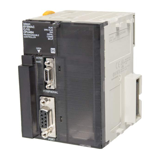
Page 203: Components
CPU Units Section 3-1 3-1-2 Components ERR/ALM 1. LED indicators PRPHL/COMM 2. Battery compartment 3. DIP switch (under battery cover) OPEN MCPWR BUSY OPEN 4. Memory Card indicators 10. Peripheral port PERIPHERAL 5. Memory Card power supply switch 9. RS-232C port PORT 8. - Page 204 CPU Units Section 3-1 Indicator Color Status Meaning COMM Orange Flashing CPU Unit is communicating (sending or receiving) via the RS-232C port. CPU Unit is not communicating via the RS-232C port. MCPWR Green Power is being supplied to the Memory Card. Flashing Flashes once: Easy backup read, write, or verify normal Flashes five times: Easy backup write malfunction...
- Page 205 CPU Units Section 3-1 DIP Switch Settings Pin no. Setting Function Usage Default Writing disabled for user program memory. Used to prevent programs from being acci- (See Note.) dently overwritten from Programming Devices (including Programming Console). Writing enabled for user program memory. The user program is automatically trans- Used to store the programs in the Memory ferred from the Memory Card when power is...
-
Page 206: Cpu Unit Memory Block Map
CPU Units Section 3-1 2. The DIP switch is not used to set the display language with CS1-H CPU Units. The language is selected on the startup display on the Programming Console. 3. The CPU Unit will not enter any mode except PROGRAM mode after back- ing up data to a Memory Card using DIP switch pin 7. - Page 207 CPU Units Section 3-1 CPU Unit Built-in RAM I/O Memory Area Drive 1: EM file memory Flash Memory (See Note 2.) (CS1-H CPU Units only) Backup User program User program Written Battery automatically The battery life is 5 years at an ambient temperature of 25°C.
- Page 208 CPU Units Section 3-1 Opening the Battery Insert a small flat-blade screwdriver into the opening at the bottom of the bat- Compartment Cover tery compartment cover and lift open the cover. Insert a small flat-blade screwdriver into the opening at the bottom of the battery compartment cover and lift open the cover.
- Page 209 CPU Units Section 3-1 Installing Inner Boards 1,2,3... 1. Press in the lever at the top of the Inner Board connector compartment and pull out. Press in the lever on the top of the Press in the lever on the bottom of cover and pull out.
-
Page 210: File Memory
File Memory Section 3-2 3-1-4 Dimensions CS1H-CPU@@-EV1 and CS1G-CPU@@-EV1 CS1H-CPU@@H, CS1G-CPU@@H File Memory For CS-series CPU Units, the Memory Card and a specified part of the EM Area can be used to store files. All user programs, the I/O Memory Area, and the Parameter Area can be stored as files. -
Page 211: Specifications Of Memory Card
File Memory Section 3-2 3-2-1 Specifications of Memory Card Specifications Model number HMC-EF183 HMC-EF672 HMC-EF372 Memory Card capacity 128 Mbytes 64 Mbytes 30 Mbytes 42.8 × 36.4 × 3.3 mm (W × H × T) Common Dimensions specifications Weight 15 g max. Current Approx. -
Page 212: Files Handled By Cpu Unit
File Memory Section 3-2 3-2-2 Files Handled by CPU Unit Files are ordered and stored in the Memory Card or EM file memory accord- ing to the file name and the extension attached to it. General-use Files File type Contents File name Extension Data files... - Page 213 File Memory Section 3-2 File type Contents File name Extension Program file All user programs REPLACE .OBJ (CPU Unit Ver. 2.0 or later only) Parameter file Not needed Easy Backup Files (except pre-version 1 CS1 File type Contents File name Extension CPU Units) Data files...
-
Page 214: Initializing File Memory
File Memory Section 3-2 3-2-3 Initializing File Memory File memory Initializing procedure Data capacity after initialization Memory Card 1. Install Memory Card into Essentially the specific capacity CPU Unit. of the Memory Card 2. Initialize the Memory Card using a Program- ming Device (including Programming Console). - Page 215 File Memory Section 3-2 Excluding Parameter File File File name and extension Data transfer direction Program file REPLACE.OBJ From Memory Card to CPU Unit I/O memory files REPLACE.IOM REPLCDM.IOM REPLCE@.IOM Parameter file Not needed 1,2,3... 1. Install the Memory Card into the CPU Unit. 2.
- Page 216 File Memory Section 3-2 Backing Up or Restoring CPU Unit Data or Data for Specific Units and Boards (except pre-version-1 CS1 CPU Units) File File name and extension Data transfer direction Program files BACKUP.OBJ CPU Unit to Memory Card (when backing up) Data files BACKUP.IOM Memory Card to CPU Unit...
-
Page 217: Memory Card Dimensions
File Memory Section 3-2 Reading/Writing I/O Memory Files in EM File Memory Using FREAD(700)and FWRIT(701) File File name and extension Data transfer direction ∗∗∗∗∗∗∗∗.IOM I/O memory files Between CPU Unit and EM file memory 1,2,3... 1. Convert the part of the EM Area specified by the first bank number into file memory in the PLC Setup. -
Page 218: Installing And Removing The Memory Card
File Memory Section 3-2 3-2-6 Installing and Removing the Memory Card Installing the Memory Card 1,2,3... 1. Pull the top end of the Memory Card cover forward and remove from the Unit. 2. Insert the Memory Card with the label facing to the right. (Insert with the ∆ on the Memory Card label and the on the CPU Unit facing each other.) Product label... - Page 219 File Memory Section 3-2 2. Press the Memory Card eject button after the BUSY indicator is no longer lit. BUSY indicator Memory Card eject button 3. The Memory Card will eject from the compartment. 4. Remove the Memory Card cover when a Memory Card is not being used. Note 1.
-
Page 220: Programming Devices
Programming Devices Section 3-3 Note 1. When a Memory Card is inserted into a computer using a Memory Card Adapter, it can be used as a standard storage device, like a floppy disk or hard disk. 2. When deleting all of the data in a Memory Card or formatting it in any way, always place it in the CPU Unit and perform the operation from the CX-Pro- grammer or a Programming Console. -
Page 221: Programming Consoles
Programming Devices Section 3-3 Function Programming Console CX-Programmer File mem- Initializing Memory Card ory opera- Initializing EM file mem- tions Transferring files between CPU Unit and file mem- Remote Between Host Link and program- Network PLC ming and Via modem monitoring Setting password protection Managing files... - Page 222 Programming Devices Section 3-3 CQM1-PRO01-E Programming Console Connection LCD area Mode selector switch . IR+ SHIFT . IR . −IR WR/LR CONT Operation keys (Install the *EM_ EM_/EXT SRCH CS1W-KS001-E Key Sheet (See Note.) ↑ RESET TEXT ↓ VRFY WRITE CS1W-CN114 (cable length: 0.05 m) Cable included with CQM1-PRO01-E Programming Console...
-
Page 223: Cx-Programmer
Programming Devices Section 3-3 3-3-3 CX-Programmer Item Details Applicable PLC CS-series, CJ-series, CP-series, NSJ-series, CV-series, C200HX/HG/HE (-Z), C200HS, CQM1, CPM1, CPM1A, SRM1, C1000H/2000H Microsoft Windows 95 (See note.), 98, NT 4.0 (Service Pack 6), 2000, Me, XP Personal computer DOS version Connection method CPU Unit’s peripheral port or built-in RS-232C port Communications... - Page 224 Programming Devices Section 3-3 cluding when using a CS1W-CN118 Cable), a peripheral bus connection cannot be used. Use a Host Link (SYSMAC WAY) connection. To connect to the port using a peripheral bus connection, prepare an RS-232C cable as described in 3-3-5 RS-232C Port Specifications. CX-Programmer Connecting Cables Unit Unit port...
- Page 225 Programming Devices Section 3-3 Using a RS-232C Cable for a IBM PC/AT or Compatible Unit Unit port Com- Computer Serial Model Length Cable notes puter port communications mode CPU Units Built-in D-Sub, 9-pin, Host Link XW2Z-200S-V RS-232C male XW2Z-500S-V port D-Sub, 9- pin, female...
- Page 226 Programming Devices Section 3-3 Cables Connecting to Serial Communications Boards/Units Cable 1 Cable 2 Unit port Serial Con- communications Con- Cable model Connector necting mode nector Cable (network) Model CS1W- D-sub, XW2Z-200S-CV/ RS-232C Not required. RS-232C Host Link CIF31 9-pin 500S-CV D-sub, 9-pin D-sub, 9-pin...
-
Page 227: Peripheral Port Specifications
(peripheral bus). Host Link connection 3. Host Link Host computer OMRON PT 4. NT Link OMRON component (CompoWay/F) 5. Serial Gateway Peripheral Port Communications Settings Connection Communications Settings Pin 4 of Front-panel PLC Setup peripheral port DIP Switch setting (See note.) -
Page 228: Rs-232C Port Specifications
Programming Devices Section 3-3 3-3-5 RS-232C Port Specifications Connector Pin Arrangement Pin No. Signal Name Direction Protection earth SD (TXD) Send data Output RD (RXD) Receive data Input RS (RTS) Request to send Output CS (CTS) Clear to send Input Power supply DR (DSR) Data set ready... - Page 229 Plug: XM2A-0901 (9-pin male) Provided with CPU Unit Note Use the special cables provided from OMRON for all connections whenever possible. If cables are produced in-house, be sure they are wired correctly. External devices and the CPU Unit may be damaged if general purpose (e.g., computer to modem) cables are used or if wiring is not correct.
- Page 230 Host Link connection 3. Host Link Host computer OMRON PT 4. NT Link General-purpose external serial device 5. No-protocol OMRON component (CompoWay/F) 6. Serial Gateway RS-232C Port Communications Settings Connection Communications Settings Pin 5 of Front-panel PLC Setup RS-232C port DIP Switch setting (See note.)
-
Page 231: Power Supply Units
Power Supply Units Section 3-4 Power Supply Units 3-4-1 Power Supply Units Model Supply voltage Output capacity Power Replacement Weight output output notification terminals function C200HW-PA204 100 to 240 V AC 5 V DC, 4.6 A, Without 500 g max. (Wide range) 26 V DC, 0.625 A, C200HW-PA204C... -
Page 232: Components And Switch Settings
Power Supply Units Section 3-4 3-4-2 Components and Switch Settings POWER indicator (Lights when 5 V is output from Power Supply Unit) External connection terminals C200HW-PA204 C200HW-PA204S AC100-240V AC input AC input INPUT Voltage (See note.) selector 24 VDC power output C200HW-PA204R C200HW-PA209R... - Page 233 Power Supply Units Section 3-4 AC Input Either a power supply of 100 to 120 V AC or 200 to 240 V AC can be selected. The C200HW-PA204C supplies 100 to 240 V AC (allowable voltage fluctua- tion range: 85 to 264 V AC). The C200HW-PA204C has a wide-range supply voltage, so voltage selector terminals are not provided.
-
Page 234: Dimensions
Power Supply Units Section 3-4 3-4-3 Dimensions C200HW-PA204 C200HW-PA204S C200HW-PA204R C200HW-PD204... -
Page 235: Selecting A Power Supply Unit
Power Supply Units Section 3-4 C200HW-PA204C PA204C C200HW-PA204C C200HW-PA204C POWER TEST 105.2 C200HW-PA209R C200HW-PD025 3-4-4 Selecting a Power Supply Unit After determining what power supply voltage is required, whether power out- put terminals and a RUN output are required, and whether replacement notifi- cation is required, calculate the current and power requirements for each Rack. - Page 236 Power Supply Units Section 3-4 Power Supply Unit Maximum current at 5 V DC C200HW-PA209R C200HW-PD025 5.3 A Current Consumption at 26 V DC (Relay Driving Power Supply) The following table shows the current that can be supplied to Units that use 26-V DC power.
- Page 237 Power Supply Units Section 3-4 Unit Differences by Manufacturing Date (Reference Information) ■ Differences in C200HW-PA204 Models Model C200HW-PA204 Manufacturing date March 2010 or later Before March 2010 Identification on C200HW-PA204/Wide AC C200HW-PA204 nameplate C200HW-PA204 / Wide AC C200HW-PA204 Input 100 to 240 V AC (wide range) 100 to 120 V AC/200 to 240 V AC specifications...
-
Page 238: Replacement Notification
Power Supply Units Section 3-4 ■ Differences in C200HW-PA204R Models Model C200HW-PA204R Manufacturing date May 2010 or later Before May 2010 Identification on C200HW-PA204R/Wide AC C200HW-PA204R nameplate C200HW-PA204R / Wide AC C200HW-PA204R Input 100 to 240 V AC (wide range) 100 to 120 V AC/200 to 240 V AC specifications (Switched with short bar.) - Page 239 Power Supply Units Section 3-4 Note The replacement notification function provides an indication of when the dete- rioration of the electrolytic capacitor will prevent the power supply functioning at its full capacity. It does not provide information on failures occurring due to other causes.
- Page 240 Power Supply Units Section 3-4 Capacity at time of manufacture Replacement required Electrolytic Remaining Replacement notification display 2.0 yr 1.5 yr 1.0 yr 0.5 yr 0 yr capacitor level life plan (7-Segment) Output Alarm output Output ON (replacement notification output) The output turns OFF when the remaining life span reaches 6 months, and the following display is repeatedly alternated.
- Page 241 Power Supply Units Section 3-4 Alarm output Turns OFF when 6 months remains Alarm output [ TIM 000 5 s ] Internal Flag T000 The Flag is programmed to allow for the delay in the alarm output at system startup. The Flag does not turn ON when the alarm output is ON (normal operation).
- Page 242 Power Supply Units Section 3-4 Power ON Display start Replacement Initial display (approx. 1.1 s) required display 0.3 s 0.1 s 0.3 s 0.1 s 0.3 s Display Alarm output 1 s max. 0.2 s max. When replacement is already required, the alarm display will follow the initial display.
- Page 243 Unit malfunction. Consult with your OMRON representative. Note If the error continues for 3 hours or longer, the replacement notification func- tion will be disabled. Even if the cause of the overheating is removed, the dis- play will continue as “Hot,”...
- Page 244 Power Supply Units Section 3-4 Startup Time The startup time of the C200HW-PA204 and C200HW-PA204R depends on the manufacturing date. Refer to the tables of differences for details. The time from when the power is turned ON until the PLC operation starts is approximately 1 second faster.
-
Page 245: Backplanes
Backplanes Section 3-5 Backplanes 3-5-1 CPU Backplanes CPU Backplane Models Standard CS-series CPU Backplanes Number of Model slots 2 slots CS1W-BC023 3 slots CS1W-BC033 5 slots CS1W-BC053 8 slots CS1W-BC083 10 slots CS1W-BC103 CS-series-only CPU Backplanes Number of Model slots 2 slots CS1W-BC022 3 slots... - Page 246 Backplanes Section 3-5 Note Always cover the connectors that are not being used with Connector Covers (sold separately) as a measure against dust. Name Model C200H Unit Connector Cover C500-COV01 CS-series Special I/O Unit Connector Cover CV500-COV01 Dimensions and Weights CS1W-BC023/022 (2 Slots) 105.25 20.2...
-
Page 247: Cs-Series Expansion Backplanes
Backplanes Section 3-5 Model Number of slots L (mm) W (mm) Weight (max.) CS1W-BC082 1,200 g CS1W-BC102 1,400 g 3-5-2 CS-series Expansion Backplanes CS-series Expansion Backplanes are used for both CS-series Expansion Racks and CS-series Long-distance Expansion Racks. CS-series Expansion Backplane Models Standard CS-series Expansion Backplane Number of slots Model... -
Page 248: C200H Expansion I/O Backplanes
Backplanes Section 3-5 Note Always cover the connectors that are not being used with Connector Covers (sold separately) as a measure against dust. Name Model C200H Unit Connector Cover C500-COV01 CS-series CPU Bus Unit Connector Cover CV500-COV01 Dimensions CS1W-BI@@@ 59.75 Model Number of slots L (mm) - Page 249 Backplanes Section 3-5 Components and Switch Settings Unit mounting slots (for mounting each Unit) Backplane mounting screws Unit connectors (4 M4 screws) I/O cable connector Power Supply Unit connector (for connecting the previous Rack: CPU Rack, CS1 Expansion Rack, Unit lock lever or C200H Expansion I/O rack) (Fix each Unit securely.
-
Page 250: I/O Control Units, I/O Interface Units, And Terminators
Backplanes Section 3-5 3-5-4 I/O Control Units, I/O Interface Units, and Terminators I/O Control Units and I/O Interface Units are used to create CS-series Long- distance Expansion Racks. Terminators are connected to the last CS-series Long-distance Expansion Rack in each series. (Up to two series of CS-series Long-distance Expansion Racks can be connected.) CS1W-IC102 I/O Control Unit An I/O Control Unit is connected to the leftmost slot on the CPU Rack or the... - Page 251 Backplanes Section 3-5 Dimensions and Weight IC102 TERM ERR OUT A OUT B OUT A OUT B 34.5 236.5 Weight: 300 g max. (including cable to Backplane) Backplane Connection Method on CPU Rack Connect to I/O cable connector. CPU Rack Series B Series A Note Connect a Terminator (CV500-TER01) to the unused connector when con-...
- Page 252 Backplanes Section 3-5 CS1W-II102 I/O Interface Unit Mount an I/O Interface Unit to the leftmost slot on each CS-series Long-dis- tance Expansion Rack. Part Names and Functions Indicator Connector to Backplane IN expansion connector OUT expansion connector (to previous Rack) (to following Rack) Indicator Indicator...
- Page 253 Backplanes Section 3-5 Connection Method Connect the I/O Interface Unit to the input I/O cable connector on the Back- plane (left side). Always connect a Terminator (CV500-TER01) to the connec- tor for the next Rack when it is not used (i.e., on the last CS-series Long- distance Expansion Rack in the series).
-
Page 254: Basic I/O Units
Basic I/O Units Section 3-6 Basic I/O Units 3-6-1 C200H and CS-series Basic I/O Units with Terminal Blocks Name Specifications Model External view/dimensions reference No. Basic Input AC Input Units 100 to 120 V AC, 100 to 120 V DC, 16 inputs CS1W-IA111 Units (with 100 to 120 V AC, 8 inputs C200H-IA121... - Page 255 Basic I/O Units Section 3-6 Name Specifications Model External view/dimensions reference No. C200H Out- Triac Output Units 1.2 A at 250 V AC max., 8 outputs, with fuse CS1W-OA201 put Units (with burnout detection circuit terminal 1 A at 250 V AC max., 8 outputs, with fuse C200H-OA221 (no blocks) burnout detection circuit...
- Page 256 Basic I/O Units Section 3-6 Components and Switch Settings C200H 10-pin/19-pin Terminal Block 10-pin terminal block 19-pin terminal block Unit mounting hooks Hooked onto Back- plane to mount Unit. Model label I/O indicator I/O indicator I/O indicator Terminal block Terminal block Terminal block connector connector...
- Page 257 Basic I/O Units Section 3-6 CS-series Basic Input Units (20-pin Terminal Block) 20-pin terminal block 16-point Unit CS1W-ID211 16-point Units CS1W-OD212 INT01 with ERR indica- IDP01 tor (load short-cir- OD211 cuit) IA111 IA211 OC211 OA211 8-point Unit CS1W-OC201 8-point Units CS1W-OA201 with ERR indica- tor (fuse burnout)
- Page 258 Basic I/O Units Section 3-6 Dimensions C200H Units with 10-pin Terminal Blocks C200H-IA121 C200H-IA221 C200H-ID211 C200H-IM211 C200H-OA221 C200H-OC221 C200H-OC223 C200H-OD216 C200H-OD213 C200H-OD411 C200H-OD214 (See note.) C200H-OA223 (See note.) Note The heights of the Units including the Backplane are 5 mm greater on the CPU Backplane and CS-series Expansion Backplane (123 and 143 mm).
- Page 259 Basic I/O Units Section 3-6 Units with 19-pin Terminal Blocks C200H-IA122 C200H-IA122V C200H-IA222 C200H-IA222V C200H-ID212 C200H-IM212 C200H-OA222V C200H-OA224 C200H-OC222 C200H-OC222V C200H-OC224 C200H-OC224V C200H-OC225 C200H-OD211 C200H-OD212 C200H-OD217 C200H-OD21A C200H-OC222N C200H-OC224N (See note.) Terminal Dimensions C200H-OC226 C200H-OC226N (See note .) Note The heights of the Units including the Backplane are 5 mm greater on the CPU Backplane and CS-series Expansion Backplane (150 and 174 mm).
-
Page 260: Interrupt Input Units
Basic I/O Units Section 3-6 CS-series Basic I/O Units (20-pin Terminal Blocks) CS1W-IA111 CS1W-IA211 CS1W-ID211 CS1W-INT01 CS1W-IDP01 CS1W-OD211 CS1W-OD212 CS1W-OA201 CS1W-OA211 CS1W-OC201 CS1W-OC211 Terminal Dimensions 3-6-2 Interrupt Input Units Functions Interrupt Input Units are used to execute interrupt programs on the rising or falling edge of an input signal (See note.). - Page 261 Basic I/O Units Section 3-6 Applicable Units Either of the following Interrupt Input Units can be used. Model Specifications No. of Units mountable to CPU Rack CS1W-INT01 24 V DC 16 inputs 2 max. C200HS-INT01 24 V DC 8 inputs 4 max.
- Page 262 Basic I/O Units Section 3-6 Components CS1W-INT01 Input indicators C200HS-INT01 Unit lock notch (fit into the Backplane) Input indicators Model label I/O indicator 10-pin Terminal Block connector Using I/O Interrupts 1,2,3... 1. Mount the Input Interrupt Unit to the CPU Rack and create the I/O tables. 2.
- Page 263 Basic I/O Units Section 3-6 MSKS(690) Instruction Specifying Rising/Falling Edge for CS1W-INT01 MSKS(690) N: Control data 1 (Interrupt Input Unit No.) S: Control data 2 (interrupt mask data) The MSKS(690) instruction is used to set rising edge or falling edge detection for each interrupt input number.
- Page 264 Basic I/O Units Section 3-6 Operand Value Details CS1W- C200HS- INT01 INT01 0, 1 0 to 3 Interrupt Input Unit Number Numbers are assigned to the Units in order from left to right. CS1W-INT01 (unit numbers 0 and 1) 0: Interrupt Input Unit 0 (interrupt task numbers 100 to 115) 1: Interrupt Input Unit 1 (interrupt task numbers 116 to 131)
- Page 265 Basic I/O Units Section 3-6 Dimensions CS1W-INT01 C200HS-INT01 (See note .) Note The height of the Unit including the Backplane is 5 mm greater on the CPU Backplane and CS-series Expansion Backplane (123 mm).
-
Page 266: Units With High-Speed Inputs
Basic I/O Units Section 3-6 3-6-3 Units with High-speed Inputs Functions The CS1W-IDP01 enables inputting pulse signals that are shorted than the cycle time of the CPU Unit. C200H High-density I/O Units (Special I/O Units) also supported high-speed inputs. I/O Units with High-speed Inputs Model Name... -
Page 267: Cs-Series Basic I/O Units With Connectors (32-, 64-, And 96-Pt Units)
Basic I/O Units Section 3-6 3-6-4 CS-series Basic I/O Units with Connectors (32-, 64-, and 96-pt Units) CS-series Basic I/O Units are classified as Basic I/O Units. Models Name Specifications Model DC Input Unit 24 V DC, 32 inputs CS1W-ID231 24 V DC, 64 inputs CS1W-ID261 24 V DC, 96 inputs... - Page 268 Basic I/O Units Section 3-6 Note Immediate refreshing (!) or refreshing using IORF(097) is possible for CS- series High-density I/O Units. Unit mounting hooks Model label Hooked onto Backplane to mount Unit. I/O indicators Display Switch for 64-point I/O Units 56-pin I/O wiring connectors Display switch...
- Page 269 Basic I/O Units Section 3-6 Dimensions Units with One Units with Two Units with 56-pin 40-pin connector 40-pin connectors connectors CS1W-ID231 CS1W-ID261 CS1W-ID291 CS1W-0D231 CS1W-0D261 CS1W-OD291 CS1W-0D232 CS1W-OD262 CS1W-OD292 CS1W-MD261 CS1W-MD291 CS1W-MD262 CS1W-MD292 CS1W-MD561 Using Pressure-welded Connector Connecting Cables: G79-@@@C-@@@-@@@ XW2Z-@@@ Using Soldered or Crimped Connector Approx.
-
Page 270: C200H Group-2 High-Density I/O Units
Basic I/O Units Section 3-6 3-6-5 C200H Group-2 High-density I/O Units C200H Group-2 High-density I/O Units are classified as Basic I/O Units. Models Name Specifications Model Appearance/ dimensions reference No. DC Input Unit 24 V DC, input current: C200H-ID216 4.1 mA typical, 32 inputs 24 V DC, input current: C200H-ID218 6 mA typical, 32 inputs... - Page 271 Basic I/O Units Section 3-6 Units with One 40-pin Connector Units with Two 40-pin Connectors 32-point Unit C200H-ID216 64-point Unit C200H-ID111 C200H-ID218 C200H-ID217 C200H-ID219 32-point Unit C200H-OD218 64-point Unit C200H-OD219 F (fuse burnt out) F (fuse burnt out) indicator indicator Dimensions 1.
-
Page 272: C200H High-Density I/O Units (Special I/O Units)
C200H High-density I/O Units (Special I/O Units) Section 3-7 C200H High-density I/O Units (Special I/O Units) C200H High-density I/O Units are classified as C200H Special I/O Units. Models Name Specifications Model Dynamic I/O mode Static I/O mode TTL Input Unit 5 V DC, 32 inputs C200H-ID501 High-speed inputs... - Page 273 C200H High-density I/O Units (Special I/O Units) Section 3-7 Back of Unit DIP switch Model RUN mode High-speed High-speed input Normal input Dynamic data inputs minimum response time output logic response pulse C200H-ID501 High- Normal 4 ms 1 ms 15 ms 2.5 ms speed input...
- Page 274 C200H High-density I/O Units (Special I/O Units) Section 3-7 C200H High-density I/O Units are classified as C200H Special I/O Units and have the following functions. Dynamic I/O Mode The High-density I/O Units (other than the C200H-ID501 and C200H-ID215) can provide high-density I/O rather than the normal output (static output mode) and I/O (static I/O mode).
- Page 275 C200H High-density I/O Units (Special I/O Units) Section 3-7 Word n Word n Word n + 1 Word n + 3 Rightmost Leftmost Rightmost Leftmost byte byte byte byte Data output DATA 0 to 7 Strobe output STB 0 STB 1 STB 2 STB 7 DATA 8 to 15 can also be output as STB 8 to 15 at the same time.
- Page 276 C200H High-density I/O Units (Special I/O Units) Section 3-7 Word n Word n Word n + 1 Word n + 3 Rightmost Leftmost Rightmost Leftmost bytes bytes bytes bytes Data input DATA 0 to 7 Strobe output STB 0 STB 1 STB 2 STB 7 DATA 8 to 15 can also be output as STB 8 to 15 at the same time.
- Page 277 C200H High-density I/O Units (Special I/O Units) Section 3-7 Dimensions Fujitsu connection cable Approx. 168 G79-@C Connecting Cable...
-
Page 278: B7A Interface Units
B7A Interface Units Section 3-8 B7A Interface Units 3-8-1 CS-series B7A Interface Units (CS-series Basic I/O Units) Overview The B7A is a 1:1 transmission path that does not require a master. A total of 16 signals are transmitted using a two-conductor or three-conductor VCTF cable (maximum length: 500 m). - Page 279 B7A Interface Units Section 3-8 Models B7A Interface Unit Specifications I/O words allocated Connectable B7A Link Terminals to Unit (See note 1.) CS1W-B7A12 32 inputs 2 input words Inputs: Two 16-point Input Terminals, one 32-point Input Terminal, or one 16-point Input (two B7A ports) Terminal CS1W-B7A02...
- Page 280 30 V rms with a 42.4-V peak or an output voltage of 60 VDC max. We recommend OMRON S8@@-se- ries Power Supply Units for the external power supplies.
- Page 281 B7A Interface Units Section 3-8 Common Specifications Item Specifications Applicable PLCs CS Series Unit classification CS-series Basic I/O Unit Transmission delay Standard (19.2 ms typical) or high-speed (3 ms typical), switchable (Switchable by using the setting switch on the front panel. Settings are read when power is turned ON or Unit is restarted.) Factory setting: Standard (19.2 ms typical)
- Page 282 B7A Interface Units Section 3-8 ■ Transmission Error Flag The corresponding Transmission Error Flag in the first word allocated to the Unit in the CPU Unit's Auxiliary Area will turn ON for each input port, as shown in the following table. Words A050 to A080 are allocated to Basic I/O Unit as information words.
- Page 283 B7A Interface Units Section 3-8 Indicators ■ CS1W-B7A12 Display Name Color Status Condition ERROR1 Port 1 trans- A transmission error has mission error occurred at port 1 of the B7A Unit. The Unit is operating normally. ERROR2 Port 2 trans- A transmission error has mission error occurred at port 2 of the B7A...
- Page 284 B7A Interface Units Section 3-8 ■ CS1W-B7A21 Display Name Color Status Condition ERROR Port 1 trans- A transmission error has mission error occurred at port 1 of the B7A Unit. The Unit is operating normally. 3 ms Transmission Orange The high-speed transmission delay setting delay (3 ms) is set.
- Page 285 B7A Interface Units Section 3-8 Display Name Color Status Condition 15IN + Input mode set- Orange The input mode is set to 15 ting inputs + error input. The input mode is set to 16 inputs. Function Setting Switch Set functionality using the DIP switch on the back of the Unit. ■...
- Page 286 B7A Interface Units Section 3-8 ■ CS1W-B7A22 Name Transmission delay Standard (19.2 ms) High-speed (3 ms) Transmission error process Hold status Reset Inputs Input mode 16 inputs 15 inputs + error input ERROR 1 indicator enable Disabled Enabled ERROR 2 indicator enable Disabled Enabled Not used.
- Page 287 B7A Interface Units Section 3-8 ■ CS1W-B7A02 Terminal Name Function Word Appearance SIG OUT1 Connect to SIG terminal on Output B7A Link Terminal. Connect to + terminal on external power supply. SIG OUT1 Connect to – power supply terminal on Output OUT1 −...
- Page 288 B7A Interface Units Section 3-8 ■ CS1W-B7A22 Terminal Name Function Word Appearance SIG OUT1 Connect to SIG terminal on Output B7A Link Ter- minal. Connect to + terminal on external power supply. SIG OUT1 Connect to – power supply terminal on Output OUT1 −...
- Page 289 B7A Interface Units Section 3-8 2. Use vinyl tape or a heat-shrink tube to cover the end of the VCTF cable sheath, as shown in the following diagram. Cover with vinyl tape or heat-shrinking tube. 2) Preparing Cable Signal Lines Attach the crimp terminals to the cable's signal lines.
- Page 290 B7A Interface Units Section 3-8 Wiring Methods Note 1. Confirm that terminals are connected correctly. If connections are incor- rect, the internal components of the B7A Interface Unit and B7A Link Ter- minal may be damaged. 2. Route the signal lines in separate ducts both inside and outside the control panel to isolate them from power lines.
- Page 291 B7A Interface Units Section 3-8 ■ Common Power Supply B7A Interface Unit B7A Link Terminal Transmission distance: 50 m max. Shielded cable: 0.75 mm max. Ground B7A Link Terminal Shielded cable: 0.75 mm max. Ground 12 to 24 VDC ■ Separate Power Supplies B7A Interface Unit 12 to 24 VDC...
-
Page 292: C200H Basic B7A Interface Units (C200H Basic I/O Units)
B7A Interface Units Section 3-8 3-8-2 C200H Basic B7A Interface Units (C200H Basic I/O Units) The Basic B7A Interface Unit used with the B7A Link Terminal allows the transmission and reception of 16-point I/O data over two wires. The following Basic B7A Interface Unit and B7A Link Terminal models are available. - Page 293 B7A Interface Units Section 3-8 Input Mode Selector The B7AI1 incorporates an input mode selector on the back panel of the Unit, with which the following modes can be set. Input mode 15 points + 1 error 16 points Function Fifteen-point input from the B7A Link Ter- Sixteen-point input from the B7A Link Ter- minal is effective.
-
Page 294: B7A Interface Units (C200H Group-2 High-Density I/O Units)
B7A Interface Units Section 3-8 3-8-3 B7A Interface Units (C200H Group-2 High-density I/O Units) Features and System Configuration Group-2 B7A Interface Unit Unit Input B7A Link Terminal Sensor Switch Transmission distance: 500 m max. Output B7A Link Terminal Lamps and other loads A B7A Interface Unit (C200H Group-2 High-density I/O Unit) used with two or four B7A Link Terminals allows the transmission and reception of 32-point or 64-point I/O data over two-conductor cables. - Page 295 B7A Interface Units Section 3-8 Comparison between B7A Interface Units Classified as Basic I/O Units and C200H Group-2 High-density I/O Units Type Models Word allocations Connectable B7A Link Terminals Transmission Transmission Points delay errors C200H C200H-B7AI1 Same as I/O Units (in order Standard types Input status 16-point Termi-...
- Page 296 B7A Interface Units Section 3-8 Type Model Transmission delay PLC connectors B7A-R@A@3 Standard (19.2 ms) B7A-R@A@8 High-speed (3 ms) Note 1. Do not connect Terminals with different transmission delays to the same Interface Unit. Doing so will cause a transmission error. 2.
- Page 297 B7A Interface Units Section 3-8 Indicator Operation The indicators depend on the model of B7A Interface Unit, as shown below. Name Color Function ERROR 1 Input trans- Lights when an error occurs in transmissions from an Input B7A Link Terminal. ERROR 2 mission error For the B7A12/22, ERROR 1 is for the first word allocated to the B7A Interface...
- Page 298 B7A Interface Units Section 3-8 C200H-B7A02 Function Transmission delay Standard (19.2 ms) High-speed (3 ms) Not used. Not used. Not used. Not used. Not used. Factory settings: All pins OFF. Transmission Delay Pin 1 is used to set the transmission delay. The same delay is used for all words allocated to the Unit.
- Page 299 B7A Interface Units Section 3-8 C200H-B7A22 Terminal Name Function Word SIG OUT1 Connect to SIG terminal on Output B7A Link Terminal. – OUT1 Connect to – power supply terminal on Output B7A Link Terminal. SIG OUT2 Connect to SIG terminal on Output B7A Link Terminal. m + 1 –...
- Page 300 B7A Interface Units Section 3-8 C200H-B7A02 Terminal Name Function Word SIG OUT1 Connect to SIG terminal on Output B7A Link Terminal. – OUT1 Connect to – power supply terminal on Output B7A Link Terminal. B2, B3 Not used. SIG OUT2 Connect to SIG terminal on Output B7A Link Terminal.
- Page 301 B7A Interface Units Section 3-8 Separate Power Supplies B7A Link Terminal B7A Interface Unit 12 to 24 V DC Transmission distance: 500 m max. B7A Link Terminal 12 to 24 V DC Transmission cable: VCTF 0.75 mm or higher 12 to 24 V DC High-speed Transmission Delays (3 ms): Shielded Cable B7A Link Terminal Common Power Supply...
- Page 302 B7A Interface Units Section 3-8 3. To prevent noise on the transmission cable, do not lay it near power cables or high-voltage lines. Specifications Item C200H-B7A12 C200H-B7A02 C200H-B7A21 C200H-B7A22 I/O points 32 input points or 32 output points 16 output points and 32 output points and 30 input points and 2 16 input points or...
-
Page 303: Analog Timer Units
Analog Timer Units Section 3-9 Analog Timer Units Analog Timer Units are classified as Basic I/O Units. Analog Timer Units have 4 built-in timers (numbers 0 to 3). The timer settings can be adjusted using the internal and external variable resistors without requiring a Programming Device. - Page 304 Analog Timer Units Section 3-9 Analog Timer Unit Timer set input Timer up output Setting value Timer pause input Resistance value Setting value Resistance value Setting value Resistance value Setting value Resistance value Components and Switch Settings Timer status indicators TM001 The SET indicators in the top row light when the corresponding timer is operating and the TIME UP indicators in the bottom row...
- Page 305 Analog Timer Units Section 3-9 Analog Timer Unit connector External variable resistor: 20 kΩ Diameter: 16 Shaft length: 15 mm Check manufacturer's specifications Analog Timer Unit Specifications Item Specifications Oscillation CR oscillation method Number of timer points Time setting Use the DIP switch to set any of the following four ranges. range 0.1 to 1 s (typical) 1 to 10 s (typical)
- Page 306 Analog Timer Units Section 3-9 Timer Operation • When the Timer Start Input turns ON, the Timer Set Bits allocated to the Analog Timer Unit (word n bits 00 to 03) turn ON, and the Analog Timer will operate. The timer set indicator (SET) on the Analog Timer Unit will light.
-
Page 307: Operating Procedures
SECTION 4 Operating Procedures This section outlines the steps required to assemble and operate a CS-series PLC system. Introduction ........... Examples . -
Page 308: Introduction
Introduction Section 4-1 Introduction The following procedure outlines the recommended steps to follow when pre- paring CS-series PLCs for operation. 1,2,3... 1. Install the provided battery in the CPU Unit (CS1 CPU Units only). 2. Installation Set the DIP switches on the front of each Unit as required. Mount the CPU Unit, Power Supply Unit, and other Units to the Backplane. - Page 309 Introduction Section 4-1 8. PLC Setup Settings With the PLC in PROGRAM mode, change the settings in the PLC Setup as necessary from the Programming Device (CX-Programmer or Program- ming Console). (Another method is to change the PLC Setup in CX-Pro- grammer and transfer it to the CPU Unit.) See 7-1 PLC Setup for details.
-
Page 310: Examples
Examples Section 4-2 Examples 1. Installation Mount the Backplane and install each Unit. When necessary, install the Inner Board or Memory Card. Make sure that the total power consumption of the Units is less than the max- imum capacity of the Power Supply Unit. 2. - Page 311 Examples Section 4-2 Note When devices other than a Programming Device are connected to the periph- eral port and RS-232C port, turn ON pin 4 and turn OFF pin 5. Programming Console Programming Device 4. Verifying the Programming Device Connection Connecting to the CX-Programmer 1,2,3...
- Page 312 Examples Section 4-2 4. When connecting online automatically, the CPU Unit is connected in RUN mode.Verify that the CX-Programmer has connected online with the PLC. 5. Change the operating mode from RUN mode to PROGRAM mode. Connecting to the Programming Console 1.
- Page 313 Examples Section 4-2 5. Clearing Memory This step is necessary only for CS1 CPU Units. It can be skipped for CS1-H CPU Units. Clearing Memory with a Programming Console Only one cyclic task can be created when programming with a Programming Console, although it is possible to create two or more interrupt tasks with interrupt task numbers ranging from 1 to 3 or 100 to 131.
- Page 314 Examples Section 4-2 Clearing Memory with CX-Programmer Multiple cyclic tasks and interrupt tasks can be created when CX-Programmer is used. Connect the computer and PLC, switch to online mode, and perform the all clear operation from the PLC Errors Window. 6.
- Page 315 Examples Section 4-2 5. Select Options and then Create. The models and positions of Units mounted to the Racks will be written to the Registered I/O Table in the CPU Unit. Using the CX-Programmer Offline Use the following procedure to create the I/O table offline with the CX-Pro- grammer and later transfer the I/O table from to the CPU Unit.
- Page 316 Examples Section 4-2 4. Select Options and then Transfer to PLC to transfer the I/O table to the CPU Unit. Note The first word allocated to each Rack can be set by selecting Rack/Slot Start Addresses from the Option Menu of the PLC IO Table Window of the CX-Pro- grammer.
- Page 317 Examples Section 4-2 000000 I/O TBL WRIT ???? Password (9713) 000000CPU BU ST? WRITE 0:CLR 1:KEEP 000000 I/O TBL Specify holding or clearing WRIT OK CPU Bus Unit information. 000000 CT00 Note With the CS1-H CPU Units, detailed I/O table error information is stored in A261 whenever the I/O tables cannot be created for any reason.
- Page 318 Examples Section 4-2 Making the Settings with the Programming Console When a Programming Console is used to set the PLC Setup, the PLC Setup settings are arranged by word addresses. Refer to the provided Programming Console settings sheet for details. Setting with a Programming Console In this example, the Programming Console is used to set the Watch Cycle Time (maximum cycle time) in 10-ms units.
- Page 319 9. Writing the Program Write the program with the CX-Programmer or a Programming Console. Unlike earlier OMRON PLCs, the CS-series PLC’s program can be divided into independently executable tasks. A single cyclic task can be written for program execution like earlier PLCs or several cyclic tasks can be written for a more flexible and efficient program.
- Page 320 Examples Section 4-2 Force-reset Check Input Wiring Activate input devices such as sensors and switches and verify that the corre- sponding indicators on the Input Units light. Also, use the Bit/Word Monitor operation in the Programming Device to verify the operation of the corre- sponding input bits.
- Page 321 Examples Section 4-2 Output OFF Bit (A50015) Turning ON the Output OFF Bit causes all outputs on Basic I/O Units and Special I/O Units to be turned OFF. The outputs will be turned OFF regardless of the PLC’s operating mode. 11-c) Trial Operation Use the Programming Console or Programming Device (CX-Programmer) to switch the CPU Unit to MONITOR mode.
- Page 322 Examples Section 4-2 When a Programming Console is being used, monitor the bits with Bit/Word Monitor or 3-word Monitor. Press the SHIFT+SET Keys to force-set a bit or press the SHIFT+RESET Keys to force-reset a bit. The forced status can be cleared by pressing the NOT Key.
- Page 323 Examples Section 4-2 12. Save and Print the Program Save To save a created program, select File - Save or File - Save As from the CX- Programmer menus. Print To print a created program, first preview the print output by selecting the desired section in the CX-Programmer's project workspace and selecting File - Print Preview from the CX-Programmer menu.
- Page 324 Examples Section 4-2...
-
Page 325: Installation And Wiring
SECTION 5 Installation and Wiring This section describes how to install a PLC System, including mounting the various Units and wiring the System. Be sure to follow the instructions carefully. Improper installation can cause the PLC to malfunction, resulting in very dangerous situations. -
Page 326: Fail-Safe Circuits
Fail-safe Circuits Section 5-1 Fail-safe Circuits Be sure to set up safety circuits outside of the PLC to prevent dangerous con- ditions in the event of errors in the PLC or external power supply. Supply Power to the PLC before Outputs If the PLC’s power supply is turned on after the controlled system’s power supply, outputs in Units such as DC Output Units may malfunction momen- tarily. - Page 327 Fail-safe Circuits Section 5-1 MCB1 Power supply MCB2 Controlled system Transformer or noise filter CS-series PLC Twisted-pair wires + DC DC voltage regulator input/output – (See PLC RUN note.) output Surge suppressor Note This configuration is possible with the C200HW-PA204R and C200HW- PA204R Power Supply Units only.
-
Page 328: Installation
Installation Section 5-2 Installation 5-2-1 Installation and Wiring Precautions Be sure to consider the following factors when installing and wiring the PLC to improve the reliability of the system and make the most of the PLC’s functions. Ambient Conditions Do not install the PLC in any of the following locations. •... - Page 329 Installation Section 5-2 • If a Programming Console will be left on the PLC, the ambient tempera- ture must be within the Programming Console’s operating range of 0°C to 45°C. Accessibility for Operation and Maintenance • To ensure safe access for operation and maintenance, separate the PLC as much as possible from high-voltage equipment and moving machinery.
-
Page 330: Installation In A Control Panel
Installation Section 5-2 • Do not install a Rack in any of the following positions. Note Always use the standard installation method. A nonstandard installation will decrease heat dissipation, and may delay the replacement notification signal (in particular for C200H-PA204C Power Supply Units with Replacement Notifi- cation), or degrade or damage the internal elements. - Page 331 Installation Section 5-2 • The mounting plate should be grounded completely and we recommend using a mounting plate that has been plated with a good conductor to improve noise resistance. • If all of the Racks cannot be mounted to the same mounting plate, the individual plates should be securely connected together using 3 wires of at least 2 mm in cross-sectional area.
-
Page 332: Mounting Height
Installation Section 5-2 Routing Wiring Ducts Install the wiring ducts at least 20 mm between the tops of the Racks and any other objects, (e.g., ceiling, wiring ducts, structural supports, devices, etc.) to provide enough space for air circulation and replacement of Units. If the C200HW-PA209R Power Supply Unit is to be used at an ambient temperature of 50 °C or higher, provide a minimum space of 80 mm. -
Page 333: Mounting Dimensions
Installation Section 5-2 5-2-4 Mounting Dimensions Backplanes CPU Backplane with 2 Slots 198.5 Four, M4 CS1W-BC023 145±0.3 CPU Backplane 172.3±0.3 Unit: mm Note Expansion Backplanes cannot be connected to 2-slot CPU Backplanes. CPU Backplane with 3, 5, 8, or 10 Slots A±0.3 Unit: mm Four, M4... -
Page 334: Mounting Units To The Backplane
Installation Section 5-2 Backplane Insulation Plates Backplane Insulation Plates can be installed on C200H I/O Backplanes only. There are four models available, corresponding to the number of slots on the Backplane. The dimensions at locations A, B, C, D, and E are shown below in millimeters for each Backplane Insulation Plate. - Page 335 Installation Section 5-2 1,2,3... 1. Mount the Unit to the Backplane by hooking the top of the Unit into the slot on the Backplane and rotating the I/O Unit downwards. (Groups A and B) Hook Backplane Lock lever 2. Make sure that the connector on the back of the Unit is properly inserted into the connector in the Backplane.
-
Page 336: Din Track Mounting
Installation Section 5-2 4. To remove a Group-A Unit, use a phillips-head screwdriver to loosen the screw at the bottom of the Unit, rotate the Unit upward, and remove it. To remove a Group-B Unit, hold down the lock lever with a tool such as a screwdriver, rotate the Unit upward, and remove it. - Page 337 Installation Section 5-2 DIN Track The following DIN Tracks are available. Model Specification PFP-50N 50 cm long, 7.3 mm high PFP-100N 1 m long, 7.3 mm high PFP-100N2 1 m long, 16 mm high DIN Track Installation 1,2,3... 1. Attach Mounting Brackets to each side (left and right) of the Backplane as shown below.
-
Page 338: I/O Connecting Cables
Installation Section 5-2 3. Loosen the hold-down bracket’s screws and slide the Backplane upward so that the Mounting Bracket and Backplane clamp securely onto the DIN Track. Tighten the screws to a torque of 0.5 N·m. DIN Track Mounting Bracket DIN Track Projections Slide this screw to the top of the... - Page 339 Installation Section 5-2 Available Models CS1 → CS1 I/O CS1 → C200H I/O C200H → C200H I/O Cables for CS1 Long-distance Connecting Cables Connecting Cables Connecting Cables Expansion Racks (CV-series I/O Connecting Cables) Model number Model number Model number Model number Cable Cable Cable...
- Page 340 Installation Section 5-2 CPU Rack CS1 Expansion Rack C200H Expansion I/O Rack Down Down Down • The following diagram shows two examples of proper Rack connections. CPU Rack CS1 → CS1 I/O Connecting Cable CS1 Expansion Rack CS1 → CS1 I/O Connecting Cable CS1 Expansion Rack CS1 →...
- Page 341 Installation Section 5-2 Example CPU Rack (Excluding the 2-slot Rack.) Total cable length: 0.7 m max. CS1 Expansion Rack Series B (0.5 m max.) Total cable length: 50 m max. CS1 Long-distance Expansion Rack CS1 Long-distance Expansion Rack Total cable length: 50 m max.
- Page 342 Installation Section 5-2 Cable Connections There are two types of connectors used in the I/O Connecting Cables: Simple locking connectors for CS-series Racks and screw-in connectors for C200H Racks. The connectors can be inserted only one way; they cannot be inserted upside down.
- Page 343 Installation Section 5-2 Mounting the I/O Control Unit to a CS-series Expansion Rack CPU Rack CS1 I/O Connecting Cable CS1 Expansion Rack CS1 Long-distance CV-series Expansion Rack Expansion I/O Control Unit I/O Cables CS1 Long-distance Expansion Rack Series B Series A I/O Interface Unit I/O Interface Unit Connecting the Simple Locking Connectors...
- Page 344 Installation Section 5-2 • An I/O bus error will occur and the PLC will stop if an I/O Connecting Cable’s connector separates from the Rack. Be sure that the connectors are secure. • A 75-mm hole will be required if the I/O Connecting Cable must pass through a hole when connecting a CS-series Long-distance Expansion Rack and a 63-mm hole will be required for Cables connecting other Racks.
- Page 345 Installation Section 5-2 2. Mount the Expansion Cable Bracket from the top, and tighten the screws (included) on the top and bottom using a Phillips screwdriver. Phillips screwdriver CS1D-ATT01 Expansion Cable Bracket Backplane Expansion Cable Tighten the screws to a torque of 0.5 N·m. Mounting Long-distance Expansion Cable Brackets Long-distance Expansion Cable Brackets can be used to prevent Expansion Cables from accidentally coming loose.
-
Page 346: Inner Board Installation
Installation Section 5-2 5-2-8 Inner Board Installation Always turn the power off before installing or removing the Inner Board. Installing or removing the Inner Board with the power on can cause the CPU Unit to malfunction, damage internal components, or cause communications errors. -
Page 347: Wiring
Wiring Section 5-3 3. Align the Inner Board with the groove and slide it into the compartment. Wiring 5-3-1 Power Supply Wiring AC Power Supply Units When 220 V AC power (200 to 240 V AC) is being supplied, be sure to remove the jumper bar that shorts the voltage selector terminals. - Page 348 Wiring Section 5-3 C200HW-PA204 or C200HW-PA204S Power Supply Unit Screws (3.5 mm head with self-raising pressure plate) 1:1 isolation transformer AC power Voltage selector (C200HW-PA204S only): source Closed for 110 V AC 100 to 200 V AC Open for 220 V AC* 24-V DC output Note The 24-V DC service power supply is provided on the C200HW-PA204S only.
- Page 349 Wiring Section 5-3 C200HW-PA204C Power Supply Unit PA204C 3.5-mm self-rising screws L2 /N 100 to 240 VAC 1:1 isolation INPUT transformer AC power source 100 to 240 V AC ALARM Alarm output (replacement notification OUTPUT output) 30 VDC, 50 mA NORMAL: ON ON: Power Supply Unit replacement ALARM: OFF...
- Page 350 Wiring Section 5-3 • Keep voltage fluctuations within the specified range: Power Supply Unit Supply voltage Allowable voltage model fluctuations C200HW-204S/PA209R 100 to 120 V AC 85 to 132 V AC 200 to 240 V AC 170 to 264 V AC C200HW-PA204/ 100 to 240 V AC 85 to 264 V AC...
- Page 351 Wiring Section 5-3 We recommend connecting a dummy load as shown in the following diagram if the maximum operating voltage of the connected device is 26.4 V (24 V +10%). Connected device (Photoelectric Switch, Sen- Dummy sor Input Unit, load etc.
- Page 352 Wiring Section 5-3 IN Unit CS1W-ID2** C200H-ID2** CPU Unit C200HW-PA204C PA204C L2 /N IN PUT ALA RM OUTPUT 30 V D C, 50 mA N ORM ALON ALARM OFF IN(N) IN (N+ 1) 24 V DC power supply Connect the negative terminal of the 24-V DC power supply to the Input Unit common (COM) terminal.
- Page 353 Wiring Section 5-3 3. Do not apply a voltage or connect a load to the alarm output that exceeds the rated voltage or load. RUN Output This output is ON whenever the CPU Unit is operating in RUN or MONITOR (C200HW-PA204R/209R) mode;...
- Page 354 Wiring Section 5-3 2. Be sure to check the setting of the voltage selector before supplying power. 3. Do not forget to remove the label from the top of the Power Supply Unit af- ter wiring the Unit. The label will block air circulation needed for cooling. DC Power Supplies Do not remove the protective label from the top of the Unit until wiring has been completed.
- Page 355 Wiring Section 5-3 Note 1. Use crimp terminals for wiring. 2. Do not connect bare stranded wires directly to the terminals. 3. Wire the power supply with the correct polarity. Supply power to all of the Power Supply Units from the same source. 4.
- Page 356 Wiring Section 5-3 CS-series PLC Other equipment Ground Ground (100 or less) (100 or less) CS-series PLC Other equipment Ground Ground (100 or less) (100 or less) CS-series PLC Other equipment (e.g., motors and inverters) !Caution Tighten the AC power supply terminal block screws to the torque of 0.8 N·m. Loose screws may result in short-circuit, malfunction, or fire.
- Page 357 Wiring Section 5-3 Recommended Wiring IC101 I102 1:1 Isolating 1:1 Isolating transformer transformer Match to the I/O Expansion Rack CPU Rack Expansion Cable. I/O Expansion Cable Control panel Control panel Wiring Susceptible to Noise IC101 I102 Noise source Expansion Rack CPU Rack I/O Expansion Cable Grounded to building...
-
Page 358: Wiring Cs-Series And C200H Basic I/O Units
Wiring Section 5-3 Wiring Terminal screws M3.5 self-rising screws Recommended wire size AWG 14 min. (2 mm min.) Recommended tightening 0.8 N·m torque Recommended crimp terminals 7 mm max. 7 mm max. Manufacturer Models Shape Applicable wire range (stranded wire) JST Mfg. - Page 359 Wiring Section 5-3 2. CS-series Basic I/O Units with 20-terminal Terminal Blocks 6.5 mm max. 7 mm max. Manufacturer Models Shape Applicable wire range (stranded wire) JST Mfg. V1.25-YS3A Y-shaped termi- 0.25 to 1.65 mm (AWG nal with sleeve 22 to 16) V1.25-M3(RAV1.25-3.5) Round terminal with sleeve Note...
-
Page 360: Wiring Cs-Series And C200H I/O Units With Connectors
C200H High-density I/O Units and CS-series Basic I/O Units with connectors use special connectors to connector to external I/O devices. The user can combine a special connector with cable or use a preassembled OMRON cable to connect a High-density I/O Unit to a terminal block or Relay Terminal. - Page 361 The following connectors are recommended for attachment to C200H Group- density I/O Units and CS- 2 High-density I/O Units and CS-series 32- and 64-point I/O Units. series Basic 32- and 64- Connection Pins OMRON set Fujitsu parts point I/O Units Solder-type C500-CE404 Socket: FCN-361J040-AU...
- Page 362 Wiring Section 5-3 from entering the Unit during wiring. (Remove the label after wiring has been completed to allow air circulation needed for cooling.) Before wiring After wiring Remove label after wiring 3. When solder-type connectors are being used, be sure not to accidentally short adjacent terminals.
- Page 363 Wiring Section 5-3 4. Assemble the connector (included or purchased separately) as shown in the following diagram. Small screws (3) Connector bar Small screws (2) Socket Connector-attaching screws Nuts (3) Cable-securing bracket Nuts (2) 5. Insert the wired connector. Connector High-density I/O Unit High-density I/O Unit Connector...
- Page 364 Wiring Section 5-3 Preassembled Cables The following examples show applications for preassembled OMRON Cables. Contact your OMRON dealer for more details. C200H Group-2 High- The following cables are compatible with C200H Group-2 High-density I/O density I/O Units Units. 1,2,3... 1. Connecting to a terminal block.
- Page 365 Wiring Section 5-3 CS-series Basic I/O Units The following cables are compatible with CS-series High-density I/O Units. with Connectors 1,2,3... 1. Connecting to a terminal block. (Two of the following Cables and Conver- sion Units are required.) CS1 Basic I/O Unit CS1 Basic I/O Unit CS1W-ID291 (96 input points) CS1W-ID291 (96 input points)
- Page 366 Wiring Section 5-3 2. Connecting to a Relay Terminal. (Two of the following Cables and Relay Terminals are required.) CS1 Basic I/O Unit CS1 Basic I/O Unit CS1W-ID291 (96 input points) CS1W-ID231 CS1W-OD291 (96 output points) CS1W-ID261 CS1W-OD292 (96 output points) CS1W-MD261 (inputs) CS1W-MD291 (48 inputs, 48 outputs) CS1W-OD291...
-
Page 367: Connecting I/O Devices
Wiring Section 5-3 2. Connecting to a Relay Terminal. C200H High-density I/O Unit C200H High-density I/O Unit C200H-OD215 (32 output points) C200H-ID215 (32 input points) C200H-OD501 (32 output points) C200H-ID501 (32 input points) C200H-MD215 (16 inputs/16 outputs) G79-@C Connecting Cable G79-@C Connecting Cable for Relay Terminals for Relay Terminals... - Page 368 Wiring Section 5-3 NPN current output Current regulator IN DC Input Unit Output Sensor 7 mA Power Supply PNP current output Sensor Power Supply Output IN AC/DC Input Unit 7 mA Voltage current output Output IN DC Input Unit Sensor Power Supply The circuit below should NOT be used for I/O devices having a voltage output.
- Page 369 Wiring Section 5-3 Note When using a reed switch as the input contact for an AC Input Unit, use a switch with an allowable current of 1 A or greater. If Reed switches with smaller allowable currents are used, the contacts may fuse due to surge cur- rents.
- Page 370 Example In this example, the sensor’s power supply voltage is used as the input to CIO 000000 and a 100-ms timer delay (the time required for an OMRON Proximity Sensor to stabilize) is created in the program. After the Comple- tion Flag for the timer turns ON, the sensor input on CIO 000001 will cause output bit CIO 000100 to turn ON.
-
Page 371: Reducing Electrical Noise
Wiring Section 5-3 Method 2 Add a control resistor as shown in the following diagram. 5-3-5 Reducing Electrical Noise I/O Signal Wiring Whenever possible, place I/O signal lines and power lines in separate ducts or raceways both inside and outside of the control panel. 1 = I/O cables 2 = Power cables Suspended duct... - Page 372 Wiring Section 5-3 External Wiring Observe the following precautions for external wiring. • When multi-conductor signal cable is being used, avoid combining I/O wires and other control wires in the same cable. • If wiring racks are parallel, allow at least 300 mm (12 inches) between the racks.
-
Page 373: Dip Switch Settings
SECTION 6 DIP Switch Settings This section describes the settings of the DIP switch and how they affect operation. DIP Switch Settings .......... -
Page 374: Dip Switch Settings
DIP Switch Settings Section 6-1 DIP Switch Settings There are two kinds of initial settings for a CS-series PLC: hardware settings and software settings. Hardware settings are made with the CPU Unit’s DIP switch and software settings are made in the PLC Setup (using a Program- ming Device). - Page 375 Peripheral port settings Default NT Link Peripheral Host Link Serial Gateway OFF Programming Console or CX-Programmer in Peripheral Bus Mode (Auto-detect connected device’s baud rate) Host OMRON CX-Pro- Host com- OMRON computer PT (NT grammer in puter or compo- or CX-...
- Page 376 Section 6-1 DIP switch PLC Setup settings settings Peripheral port settings Default NT Link Peripheral Host Link Serial protocol Gateway OFF Host OMRON Standard CX-Pro- Host com- OMRON computer PT (NT external grammer in puter or compo- or CX- Link)
-
Page 377: Plc Setup
SECTION 7 PLC Setup This section describes the settings in the PLC Setup and how they are used to control CPU Unit operation. PLC Setup ........... . 7-1-1 Overview of the PLC Setup . -
Page 378: Plc Setup
PLC Setup Section 7-1 PLC Setup 7-1-1 Overview of the PLC Setup The PLC Setup contains basic CPU Unit software settings that the user can change to customize PLC operation. These settings can be changed from a Programming Console or other Programming Device. The various settings for the CPU Unit are made in the PLC Setup. - Page 379 PLC Setup Section 7-1 Cases when settings must be changed Setting(s) to be changed The RS-232C port will not be used with the Programming Console or CX- RS-232C Port Settings Programmer (peripheral bus) communications speed auto-detection and will not use the default host link communications settings such as 9,600 bps. Note Pin 5 of the DIP switch on the front of the CPU Unit must be OFF to change the PLC Setup settings.
- Page 380 PLC Setup Section 7-1 7-1-2 PLC Setup Settings The Programming Console addresses given in this section are used to access and change settings in the PLC Setup when using a Programming Console or the Programming Console function of an NS-series Programming Terminal. The PLC Setup is stored in the Parameter Area, which can be accessed only from a Programming Device.
- Page 381 PLC Setup Section 7-1 Mode Setting Programming Settings Function Related Console address flags and setting’s words effective- Word Bit(s) ness Use programming console This setting determines whether the Takes effect (PRCN): Startup Mode will be the mode set on at startup Programming Console’s the Programming Console’s mode switch mode switch...
- Page 382 PLC Setup Section 7-1 7-1-2-2 CPU Unit Settings (CPU Settings Tab Page on the CX-Programmer) Execute Process Detect Low Battery Programming Settings Function Related New set- Console address flags and ting’s effec- words tiveness Word Bit(s) +128 0: Detect This setting determines whether CPU Unit A40204 (Bat- Takes effect battery errors are detected.
- Page 383 PLC Setup Section 7-1 Stop CPU on Instruction Error (Instruction Error Operation) Programming Settings Function Related Console address flags and setting’s words effective- Word Bit(s) ness +197 0: Continue This setting determines whether instruction A29508, At start of 1: Stop errors (instruction processing errors (ER) A29509, operation.
- Page 384 PLC Setup Section 7-1 Background Execution Settings Table Data Process Instructions Programming Settings Function Related Console address flags and setting’s words effective- Word Bit(s) ness +198 0: Not executed in This setting determines if Table Data Start of oper- background Instructions will be processed over multiple ation cycle times (i.e., processed in the back-...
- Page 385 PLC Setup Section 7-1 7-1-2-3 FB Communications Instruction Settings (Settings for OMRON FB Library) The following PLC Setup settings are used only when using the OMRON FB Library. Number of Resends Programming Settings Function Related Console address flags and setting’s...
- Page 386 PLC Setup Section 7-1 7-1-2-4 Time and Interrupt Settings (CX-Programmer Timings Tab Page) Enable Watch Cycle Time Setting Programming Settings Function Related Console address flags and setting’s words effective- Word Bit(s) ness +209 0: Default Set to 1 to enable the Watch Cycle Time A40108 Takes effect 1: Bits 0 to 14...
- Page 387 PLC Setup Section 7-1 Schedule Interrupt Interval Programming Settings Function Related Console address flags and setting’s words effective- Word Bit(s) ness +195 0 to 3 0 hex: 10 ms Sets the time interval for the scheduled Takes effect 1 hex: 1.0 ms interrupt task.
- Page 388 PLC Setup Section 7-1 7-1-2-5 Special I/O Unit Cyclic Refreshing (CX-Programmer SIOU Refresh Tab Page) Item Programming Settings Function Related Console address flags and setting’s words effective- Word Bit(s) ness Cyclic Refresh- +226 0 to 15 0: Enabled These settings determine whether Takes ing of Units 0 to 1: Disabled...
- Page 389 PLC Setup Section 7-1 7-1-2-6 Basic I/O Unit Input Response Times (Unit Settings Tab Page on the CX- Programmer) Item Programming Settings Function Related New set- Console address flags and ting’s words effective- Word Bit(s) ness Rack 0, Slot 0 0 to 7 00: 8 ms Sets the input response time...
- Page 390 PLC Setup Section 7-1 7-1-2-7 Host Link (RS-232C) Port Tab Page The following settings are valid when pin 5 on the DIP switch on the CPU Unit is ON. Host Link Settings Communications Settings Programming Settings Function Related When set- Console address flags and ting is read...
- Page 391 PLC Setup Section 7-1 Format: Stop Bits Programming Settings Function Related When set- Console address flags and ting is read words by CPU Unit Word Bit(s) +160 0: 2 bits These settings are valid only when the com- A61902 At the next 1: 1 bit munications mode is set to host link or no- (RS-232C...
- Page 392 PLC Setup Section 7-1 NT Link Settings Mode: Communications Mode Programming Settings Function Related When set- Console address flags and ting is read words by CPU Unit Word Bit(s) +160 8 to 11 02: 1:N NT Link This setting determines whether the RS- A61902 At the next 232C port will operate in host link mode or...
- Page 393 PLC Setup Section 7-1 Baud Rate (bps) Programming Settings Function Related When set- Console address flags and ting is read words by CPU Unit Word Bit(s) +161 0 to 7 00: 9,600 bps Settings 00 and 06 through 0A are valid A61902 At the next 06: 9,600 bps...
- Page 394 PLC Setup Section 7-1 Parity Programming Settings Function Related When set- Console address flags and ting is read words by CPU Unit Word Bit(s) +160 00 to 01 00 Hex: Even This setting is valid only in no-protocol com- A61902 At the next 01 Hex: Odd munications mode.
- Page 395 PLC Setup Section 7-1 Start Code/End Code Programming Settings Function Related When set- Console address flags and ting is read words by CPU Unit Word Bit(s) +164 8 to 15 00 to FF Start code: Set this start code only when the A61902 At the next start code is enabled (1) in bits 12 to 15 of...
- Page 396 PLC Setup Section 7-1 Data Bits Programming Settings Function Related New set- Console address flags and ting’s effec- words tiveness Word Bit(s) +160 0: 7 bits These settings are valid when the RS-232C A61901 Takes effect 1: 8 bits Port Settings Selection is set to 1: PLC (RS-232C the next Setup.
- Page 397 PLC Setup Section 7-1 Response Monitoring Time Programming Settings Function Related New set- Console address flags and ting’s effec- words tiveness Word Bit(s) +167 8 to 15 00: 5 s Monitors the time from when the FINS com- A61902 Takes effect 01 to FF: 100 to mand that has been converted into the (RS-232C...
- Page 398 PLC Setup Section 7-1 Format: Data Bits Programming Settings Function Related When set- Console address flags and ting is read words by CPU Unit Word Bit(s) +144 0: 7 bits These settings are valid only when the com- A61901 At the next 1: 8 bits munications mode is set to Host link.
- Page 399 PLC Setup Section 7-1 NT Link Settings Mode: Communications Mode Programming Settings Function Related When set- Console address flags and ting is read words by CPU Unit Word Bit(s) +144 8 to 11 02: 1:N NT Link This setting determines whether the RS- A61902 At the next 232C port will operate in host link mode or...
- Page 400 PLC Setup Section 7-1 Baud Rate (bps) Programming Settings Function Related When set- Console address flags and ting is read words by CPU Unit Word Bit(s) +145 0 to 7 00: 9,600 bps The following settings are valid for the A61901 At the next 06: 9,600 bps...
- Page 401 PLC Setup Section 7-1 Format: Parity Programming Settings Function Related New set- Console address flags and ting’s effec- words tiveness Word Bit(s) +144 0 to 1 00: Even These setting is valid only when the commu- A61901 Takes effect 01: Odd nications mode is set to Host Link.
- Page 402 PLC Setup Section 7-1 Peripheral Service Execution Time Programming Settings Function Related When set- Console address flags and ting is read words by CPU Unit Word Bit(s) +219 00 to 07 00 to FF (hex) This parameter sets the time slice for A266 and At start of peripheral servicing (0.1 to 25.5 ms in 0.1-...
- Page 403 PLC Setup Section 7-1 Set Time to All Events (Fixed Peripheral Servicing Time) Enable Fixed Servicing Time Programming Settings Function Related When set- Console address flags and ting is read words by CPU Unit Word Bit(s) +218 0: Default* Set to 1 to enable the fixed peripheral ser- At start of 1: Bits 0 to 7 vicing time in bits 0 to 7.
- Page 404 PLC Setup Section 7-1 7-1-2-10 FINS Protection Tab Page (Protection Against FINS Writes Across Networks) (CS-series CPU Unit Ver. 2.0 Only) Enabling FINS Write Protection (Use FINS Write Protection) Programming Settings Function Related New set- Console address flags and ting’s words effective- Word...
-
Page 405: Explanations Of Plc Setup Settings
Explanations of PLC Setup Settings Section 7-2 Explanations of PLC Setup Settings Basic I/O Unit Input Response Time The input response time can be set for CS-series Basic I/O Units by Rack and Slot number. Increasing this value reduces the effects of chattering and noise. Decreasing this value allows reception of shorter input pulses, (but do not set the ON response time or OFF response time to less than the cycle time). - Page 406 Explanations of PLC Setup Settings Section 7-2 OFF (0): IOM Hold Bit cleared at start-up Non-retained parts Non-retained parts Power Power of I/O memory of I/O memory: Cleared Mode switch Retained Power on Not retained IOM Hold Bit: 1 IOM Hold Bit: 0 Not retained when (ON) (OFF)
- Page 407 Explanations of PLC Setup Settings Section 7-2 OFF (0): Forced Status Hold Bit cleared at start-up Power Power Forced bit status Forced bit status Mode switch Retained Power on Not retained Forced Status Forced Status Not retained when Hold Bit: 1 (ON) Hold Bit: 0 (OFF) power is turned ON (1): Forced Status Hold Bit protected at start-up...
- Page 408 Explanations of PLC Setup Settings Section 7-2 Detect Low Battery This setting determines whether CPU Unit battery errors are detected. Set the PLC Setup so that battery errors are not detected when using battery-free operation. Refer to information on battery-free operation in the CS/CJ Series Programming Manual for details.
- Page 409 Explanations of PLC Setup Settings Section 7-2 Note 1. The actual starting file memory bank is stored in A344 (EM File Memory Starting Bank). When the settings in the PLC Setup have been changed but the EM Area hasn’t been formatted, the PLC Setup setting will differ from the actual file memory setting in the EM Area.
- Page 410 Explanations of PLC Setup Settings Section 7-2 RS-232C Port Settings These settings are effective only when pin 5 of the DIP switch on the front of the CPU Unit is OFF. The default settings for the RS-232C port are: host link mode, 1 start bit, 7 data bits, even parity, 2 stop bits, and a baud rate of 9,600 bps.
- Page 411 Explanations of PLC Setup Settings Section 7-2 Start code setting End code setting None CR+LF None DATA DATA+ED DATA+CR+LF ST+DATA ST+DATA+ED ST+DATA+CR+LF Scheduled Interrupt Time Units This setting determines the time units for the scheduled interrupt interval set- tings. Set the scheduled interrupt interval from the program with MSKS(690). Note This setting cannot be changed while the CPU Unit is in RUN or MONITOR mode.
- Page 412 Explanations of PLC Setup Settings Section 7-2 Minimum Cycle Time Set the minimum cycle time to a non-zero value to eliminate inconsistencies in I/O responses. This setting is effective only when the actual cycle time is shorter than the minimum cycle time setting. If the actual cycle time is longer than the minimum cycle time setting, the actual cycle time will remain unchanged.
- Page 413 Explanations of PLC Setup Settings Section 7-2 Peripheral servicing is performed at the end of the cycle, just after I/O refresh- ing. Power ON Initialization Common processes Program execution (Tasks Cycle executed in time order) I/O refreshing Peripheral servicing The following table shows a breakdown of the peripheral servicing time. Peripheral servicing time Default value Setting range...
- Page 414 Explanations of PLC Setup Settings Section 7-2 Power OFF Interrupt Task This setting determines whether or not a power OFF interrupt task will be exe- cuted when a power interruption is detected. (When this setting is set to 0, the regular program will just stop when a power interruption is detected.) The power OFF interrupt task will be stopped when the power hold time (pro- cessing time after power interrupt + power OFF detection delay time) has...
- Page 415 Explanations of PLC Setup Settings Section 7-2 Special I/O Unit Cyclic Refreshing When a Special I/O Unit will be refreshed in an interrupt task by IORF(097), always disable cyclic refreshing for that Unit with this setting. The expected results will not be achieved and the Interrupt Task Error Flag (A40213) will be turned ON if IORF(097) is executed in an interrupt task during normal I/O refreshing.
- Page 416 Explanations of PLC Setup Settings Section 7-2...
-
Page 417: I/O Allocations
SECTION 8 I/O Allocations This section describes I/O allocations to Basic I/O Units, Special I/O Units, and CPU Bus Units, and data exchange with CPU Bus Units. I/O Allocations ..........8-1-1 Unit Types. -
Page 418: I/O Allocations
I/O Allocations Section 8-1 I/O Allocations In CS-series PLCs, memory must be allocated to the Units mounted in the PLC. I/O tables containing the models and locations of all Units and the allo- cations made to each must be created and these I/O tables must be regis- tered in the CPU Unit. - Page 419 I/O Allocations Section 8-1 Special I/O Units Special I/O Units CS-series Special I/O Units Special I/O Unit Area CIO 2000 to CIO 2959 Allocation (Each Unit is allocated ten words based on its unit number setting.) Note 1. Although there are 96 unit number settings, a maximum of 80 Units can actually be mounted to a PLC because that is the maximum number of slots possible.
-
Page 420: Creating I/O Tables
I/O Allocations Section 8-1 8-1-2 Creating I/O Tables There are two ways to allocate I/O memory to CS-series Units. • Create the I/O tables online based on the Units actually mounted to the PLC. This can be done from either the CX-Programmer or a Programming Console. - Page 421 I/O Allocations Section 8-1 I/O Table Creation with CX-Programmer Use the following procedure to create the I/O tables online with the CX-Pro- grammer. 1,2,3... 1. Double-click IO Table in the project tree in the main window. The I/O Table Window will be displayed. 2.
- Page 422 I/O Allocations Section 8-1 4. When all the desired Units have been assigned to slots, select Options - Transfer to PLC. The I/O tables will be transferred. With the CX-Programmer, you can also assign any desired word to an I/O Unit regardless of it’s position on the Racks.
-
Page 423: I/O Allocation Methods
I/O Allocation Methods Section 8-2 Overview Method Operation Allocations Rack allocation Slot allocation order order within Rack Using actual Perform I/O table Automatic allocations according to In order from Rack 0 Left to right from mounted Units creation online. mounting position to Rack 7 slot 00 Not using... - Page 424 I/O Allocation Methods Section 8-2 Allocation Methods When I/O tables are created in the order of the Racks and the order that Units are mounted, I/O words will be allocated as described below. If a Program- ming Console or the CX-Programmer is connected online and the I/O tables are created automatically according to the Units that are actually mounted, the CPU Unit will automatically create and register the I/O tables.
- Page 425 I/O Allocation Methods Section 8-2 Example 3 The following example shows the I/O allocations to 5 Basic I/O Units in the CPU Rack. Two slots are filled with Dummy Units to reserve I/O words for those slots. CPU Rack served served 0000 0002...
- Page 426 I/O Allocation Methods Section 8-2 Example The following example shows the I/O allocation to Basic I/O Units in the CPU Rack and two CS-series Expansion Racks. CPU Rack 0000 0001 0003 0007 0008 0002 0006 0009 CS-series Expansion Empty Rack 0010 0011 0013...
- Page 427 I/O Allocation Methods Section 8-2 Reserving I/O Words for Expected Changes If the system configuration will be changed at a later date, changes to the pro- gram can be minimized by reserving I/O words in advance for future Unit changes or additions. To reserve I/O words, edit the I/O table with the CX-Pro- grammer.
-
Page 428: I/O Allocations To Special I/O Units
I/O Allocation Methods Section 8-2 8-2-2 I/O Allocations to Special I/O Units Special I/O Units include the following Units: • CS-series Special I/O Units • C200H Special I/O Units Each of these Units is allocated ten words in the Special I/O Unit Area (CIO 2000 to CIO 2959) according the unit number set on the Unit. -
Page 429: I/O Allocations To Cpu Bus Units
I/O Allocation Methods Section 8-2 8-2-3 I/O Allocations to CPU Bus Units Each CPU Bus Unit is allocated 25 words in the CPU Bus Unit Area (CIO 1500 to CIO 1899) according the unit number set on the Unit. CPU Bus Units can be mounted to the CPU Rack or CS-series Expansion Racks. -
Page 430: Allocating First Words To Racks
Allocating First Words to Racks Section 8-3 Example The following example shows the word allocation to 3 Slave Racks. SYSMAC BUS Remote I/O Master Unit SYSMAC BUS Remote I/O 1 2 3 4 5 6 7 8 19 20 21 22 23 24 25 26 9 10 11 12 13 14 15 16 17 18 Remote I/O Slave Rack Slave Unit with... - Page 431 Allocating First Words to Racks Section 8-3 For Racks in which the first word address has not been set, words are allo- cated in rack-number order (lowest to highest) continuing from the last word allocated to the previous rack and starting with CIO 0000 on the first Rack for which the first word is not set.
- Page 432 Allocating First Words to Racks Section 8-3 Note Rack numbers (0 to 7) are fixed according to the order that the Racks are physically connected with cable. The CPU Rack is always Rack 0 and the other Racks are, in order, Racks 1 to 7. These numbers cannot be changed. In the above example, the shaded Racks are allocated words starting from the specified first words.
-
Page 433: Allocating First Words To Slots
Allocating First Words to Slots Section 8-4 Confirming First Rack Word Settings on a Programming Console With a CS1-H CPU Unit, the Programming Console can be used to check whether or not the first word has been set on a Rack. Use the following proce- dure. - Page 434 Allocating First Words to Slots Section 8-4 Each first word set for a slot creates a group starting with that slot. Words are allocated starting from the specified word to the first slot in the group and con- tinuing left to right allocating consecutive words to each Unit until the next group (i.e., until the next Unit for which a first slot word is set).
- Page 435 Allocating First Words to Slots Section 8-4 1,2,3... 1. Select the Rack/Slot Start Addresses from the Option Menu on the I/O Table Window. The following dialog box will be displayed. 2. Select the Slot Start Addresses Settings Option and click the OK Button. 3.
-
Page 436: Detailed Information On I/O Table Creation Errors
Detailed Information on I/O Table Creation Errors Section 8-5 Precautions in Setting First Slot Words When the I/O tables are edited, the CX-Programmer checks for any duplica- tions in word allocations caused by first word settings. It is conceivable, how- ever, that duplications in word allocations could occur after the I/O tables have been registered, e.g., as the result of replacing a 1-word Unit with a 2-word Unit. - Page 437 Data Exchange with CPU Bus Units Section 8-6 The Special I/O Unit Area ranges from CIO 2000 to CIO 2959 (10 words × 96 Units). Special I/O Unit CPU Unit Special I/O Unit Area 10 words/Unit Transferred in I/O refreshing Transfer of Words Allocated in DM Area C200H Special I/O Units The 100 words allocated to each Unit are transferred from the DM Area to the...
-
Page 438: Disabling Special I/O Unit Cyclic Refreshing
Data Exchange with CPU Bus Units Section 8-6 FINS Commands The CMND(490) instruction can be added to the ladder program to issue a FINS command to the Special I/O Unit. Special I/O Unit CPU Unit The FINS command is transmitted when CMND(490) has been executed in the program. -
Page 439: Cpu Bus Units
Data Exchange with CPU Bus Units Section 8-6 11 seconds during operation. A CPU Unit service monitoring error will oc- cur in the Special I/O Unit if it is not refreshed every 11 seconds. 8-6-3 CPU Bus Units Data can be exchanged between CPU Bus Units and the CPU Unit through the CPU Bus Unit Area, the DM Area, or FINS commands. - Page 440 Data Exchange with CPU Bus Units Section 8-6 CPU Bus Unit CPU Unit DM Area for CPU Bus Units Transferred when power is turned on or the Unit is restarted. 100 words/Unit Transferred each cycle and when necessary. FINS Commands The CMND(490) instruction can be added to the ladder program to issue a FINS command to the CPU Bus Unit.
-
Page 441: Memory Areas
SECTION 9 Memory Areas This section describes the structure and functions of the I/O Memory Areas and Parameter Areas. Introduction ........... I/O Memory Areas . -
Page 442: Introduction
Introduction Section 9-1 Introduction The CPU Unit’s memory (RAM with battery back-up) can be divided into three parts: the User Program Memory, I/O Memory Area, and Parameter Area. This section describes the I/O Memory Area and Parameter Area. I/O Memory Area This region of memory contains the data areas which can be accessed by instruction operands. -
Page 443: I/O Memory Areas
I/O Memory Areas Section 9-2 I/O Memory Areas 9-2-1 I/O Memory Area Structure The following table shows the basic structure of the I/O Memory Area. Area Size Range Exter- Word Access Change Status at Forcing nal I/O access access from startup bit sta- Read... - Page 444 I/O Memory Areas Section 9-2 Area Size Range Exter- Word Access Change Status at Forcing nal I/O access access from startup bit sta- Read Write alloca- Pro- or mode tion gram- change ming Device Auxiliary Area 15,360 A000 to Varies bits (960 A447 from...
- Page 445 I/O Memory Areas Section 9-2 10. The Function Block Holding Area words are allocated from H512 to H1535. These words can be used only for the function block instance area (inter- nally allocated variable area).
-
Page 446: Overview Of The Data Areas
I/O Memory Areas Section 9-2 9-2-2 Overview of the Data Areas The data areas in the CS-series I/O Memory Area are described in detail below. CIO Area It isn’t necessary to input the “CIO” acronym when specifying an address in the CIO Area. - Page 447 I/O Memory Areas Section 9-2 Note 1. It is possible to use CIO 0320 to CIO 0999 for I/O words by making the ap- propriate settings for the first words on the Racks. Settings for the first words on the Racks can be made using the CX-Programmer to set the first Rack addresses in the I/O table.
- Page 448 I/O Memory Areas Section 9-2 CS-series DeviceNet Area These words are allocated to Slaves for DeviceNet Remote I/O Communica- tions for CS-series DeviceNet Units (CS1W-DRM21). Allocations are fixed and cannot be changed. Be sure that allocates to not overlap with those used for other I/O points.
- Page 449 I/O Memory Areas Section 9-2 Auxiliary Area (AR) The Auxiliary Area contains flags and control bits used to monitor and control PLC operation. This area is divided into two parts: A000 to A447 are read- only and A448 to A959 can be read or written. Refer to 9-16 Auxiliary Area for details on the Auxiliary Area.
- Page 450 I/O Memory Areas Section 9-2 Extended Data Memory Area (EM) The EM Area is a multi-purpose data area that can be accessed in word-units only. These words retain their content when the PLC is turned on or the oper- ating mode is switched between PROGRAM mode and RUN or MONITOR mode.
-
Page 451: Data Area Properties
I/O Memory Areas Section 9-2 (RUN) status and OFF when the cyclic task hasn’t been executed (INI) or is in standby (WAIT) status. Index Registers (IR) These registers (IR0 to IR15) are used to store PLC memory addresses (absolute memory addresses in RAM) to indirectly address words in I/O mem- ory. -
Page 452: Precautions In Using C200H Special I/O Units
Precautions in Using C200H Special I/O Units Section 9-3 Content After Mode Change or Power Interruption Area PLC Power OFF to ON Mode Changed IOM Hold Bit Cleared IOM Hold Bit Held IOM Hold IOM Hold IOM Hold IOM Hold IOM Hold IOM Hold Bit OFF... -
Page 453: Cio Area
CIO Area Section 9-4 Restrictions There are special restrictions in programming, allocations, and data communi- cations with the CPU Unit for the following C200H Special I/O Units. Refer to Appendix F Restrictions in Using C200H Special I/O Units for details. Unit Model number ASCII Units... - Page 454 CIO Area Section 9-4 If the IOM Hold BIt (A50012) is ON and the PLC Setup’s “IOM Hold Bit Status at Startup” setting is set to protect the IOM Hold Bit, the contents of the I/O Area won’t be cleared when the PLC’s power supply is cycled. All I/O bits, including outputs, will retain the status that they had before the PLC was turned off.
- Page 455 CIO Area Section 9-4 Note Immediate refreshing will be performed for input bits allocated to Basic I/O Units only (excluding C200H Group-2 High-density I/O Units and Basic I/O Units mounted in Remote I/O Slave Racks), not High-density I/O Units which are Special I/O Units.
- Page 456 CIO Area Section 9-4 Input Unit CPU Unit Switch 0 Switch 16 Switch 1 Switch 17 Switch 15 Read Switch 31 when IORF (097) execu- ted. Limitations on Input bits There is no limit on the number of times that input bits can be used as nor- mally open and normally closed conditions in the program and the addresses can be programmed in any order.
- Page 457 CIO Area Section 9-4 Ladder symbol Mnemonic 000201 OUT 000201 CPU Unit CIO 000201 Bit allocation Output Unit Actuator Once each cycle Immediate Refreshing When the immediate refreshing variation of an instruction is specified by inputting an exclamation point just before the instruction, and the instruction’s operand is an output bit or word, the content of the word containing the bit or the word itself will be output just after the instruction is executed.
- Page 458 CIO Area Section 9-4 IORF(097) Refreshing When IORF(097) (I/O REFRESH) is executed, the ON/OFF status of output bits in the specified range of words is output to their external devices. This I/O refreshing is performed in addition to the normal I/O refreshing performed once each cycle.
-
Page 459: C200H Devicenet Area
C200H DeviceNet Area Section 9-5 C200H DeviceNet Area The C200H DeviceNet Area is divided into two parts: 1,2,3... 1. The DeviceNet Output Area contains 50 words with addresses ranging from CIO 0050 to CIO 0099. 2. The DeviceNet Input Area contains 50 words with addresses ranging from CIO 0350 to CIO 0399. -
Page 460: Cs-Series Devicenet Area
CS-series DeviceNet Area Section 9-6 DeviceNet Area The contents of the DeviceNet Area will be cleared in the following cases: Initialization 1,2,3... 1. The operating mode is changed between PROGRAM and RUN or MONI- TOR mode and the IOM Hold Bit is OFF. 2. - Page 461 CS-series DeviceNet Area Section 9-6 Note If the DeviceNet Unit is set to use the I/O slave function, the following words are also allocated. Area Master to Slave Slave to Master (Input Word) (Output Word) Fixed Allocation Area 1 CIO 3370 CIO 3270 Fixed Allocation Area 2 CIO 3570...
-
Page 462: Plc Link Area
Note The Link Area (CIO 1000 to CIO 1063) is used to exchange data between PLCs in a PLC Link system, just as the LR Area is used in other OMRON PLCs. The flags in the PLC Link Area indicate the status of PLC Link opera- tions. - Page 463 PLC Link Area Section 9-7 CIO Area Flags The following table shows the allocation of the CIO Area flags related to PLC Link operation. (The numbers in parentheses show the allocation for multilevel systems; operating level 0 is #0 and operating level 1 is #1.) Flag type CIO 0247 CIO 0248...
-
Page 464: Data Link Area
Data Link Area Section 9-8 Data Link Area Data Link Area addresses range from CIO 1000 to CIO 1199 (CIO bits 100000 to 119915). Words in the Link Area are used for data links when LR is set as the data link area for Controller Link Networks. It is also used for PLC Links. -
Page 465: Cpu Bus Unit Area
CPU Bus Unit Area Section 9-9 4. PLC operation is stopped when a fatal error other than an FALS(007) error occurs. (The contents of the Link Area will be retained if FALS(007) is ex- ecuted.) IOM Hold Bit Operation If the IOM Hold BIt (A50012) is ON and the PLC Setup’s “IOM Hold Bit Status at Startup”... -
Page 466: Inner Board Area
Inner Board Area Section 9-10 Unit number Allocated words CIO 1850 to CIO 1874 CIO 1875 to CIO 1899 The function of the 25 words depends upon the CPU Bus Unit being used. For details, refer to the Unit’s operation manual. Words in the CPU Bus Unit Area that aren’t allocated to CPU Bus Units can be used only in the program. -
Page 467: Special I/O Unit Area
Special I/O Unit Area Section 9-11 Inner Board Area The contents of the Inner Board Area will be cleared in the following cases: Initialization 1,2,3... 1. The operating mode is changed from PROGRAM mode to RUN/MONITOR mode or vice-versa and the IOM Hold Bit is OFF. 2. - Page 468 Special I/O Unit Area Section 9-11 Each Special I/O Unit is allocated 25 words based on its unit number, as shown in the following table. Unit number Allocated words C200H CS-series Special I/O Units Special I/O Units CIO 2000 to CIO 2009 Valid unit numbers Valid unit numbers CIO 2010 to CIO 2019...
-
Page 469: Sysmac Bus Area
SYSMAC BUS Area Section 9-12 9-12 SYSMAC BUS Area The SYSMAC BUS Area contains 80 words with addresses ranging from CIO 3000 to CIO 3079. Words in the SYSMAC BUS Area are allocated to Slave Racks connected to Wired or Optical SYSMAC BUS Remote I/O Master Units (C200H-RM201 or C200H-RM001-PV1). -
Page 470: I/O Terminal Area
I/O Terminal Area Section 9-13 1,2,3... 1. Ten words are allocated to each Rack based on the rack number set on the Slave Unit. 2. The ten words in each Rack are allocated to the slots in the Rack from left to right (one word/slot). -
Page 471: Work Area
Work Area Section 9-14 Both Slave Racks and SYSMAC BUS Slaves other than Slave Racks (such as I/O Terminals) can be connected. Slave Racks are allocated words in the SYSMAC BUS Area. Refer to 9-12 SYSMAC BUS Area for details. Wired or Optical Master Unit CPU Unit I/O Terminal Area... -
Page 472: Holding Area
Holding Area Section 9-15 1,2,3... 1. The operating mode is changed from PROGRAM to RUN or MONITOR mode or vice-versa and the IOM Hold Bit is OFF. 2. The PLC’s power supply is cycled and the IOM Hold Bit is OFF or not pro- tected in the PLC Setup. -
Page 473: Auxiliary Area
Auxiliary Area Section 9-16 3. The Function Block Holding Area words are allocated from H512 to H1535. These words can be used only for the function block instance area (inter- nally allocated variable area). These words cannot be specified as instruc- tion operands in the user program. - Page 474 Auxiliary Area Section 9-16 Writing Auxiliary Area Data The following operations can be performed from a Programming Device to write data in the Auxiliary Area. • Using the CX-Programmer: Online set/reset (not force-set/force-reset) (except pre-version-1 CS1 CPU Units), changing present values when monitoring programming addresses (set values dialog box), or transfer- ring data to the PLC after editing the PLC data tables.
- Page 475 Auxiliary Area Section 9-16 CPU Bus Unit Flags/Bits Name Address Description Access CPU Bus Unit Initialization A30200 to These flags correspond to CPU Bus Units 0 to 15. A flag will Read-only Flags A30215 be ON while the corresponding Unit is initializing after the power is turned ON or the Unit’s Restart Bit (in A501) is turned ON.
- Page 476 Auxiliary Area Section 9-16 Name Address Description Access 100-ms Incrementing Free A001 This word contains the system timer used after the power is Read-only Running Timer turned ON. 0000 hex is set when the power is turned ON and this value is automatically incremented by 1 every 100 ms.
- Page 477 Auxiliary Area Section 9-16 Debugging Information ■ Online Editing Name Address Description Access Online Editing Wait Flag A20110 ON when an online editing process is waiting. Read-only (An online editing request was received while online editing was disabled.) Online Editing Processing A20111 ON when an online editing process is being executed.
- Page 478 Auxiliary Area Section 9-16 Name Address Description Access File Missing Flag A34311 ON when an attempt is made to read a file that doesn’t exist, Read-only or an attempt is made to write to a file in a directory that doesn’t exist.
- Page 479 Auxiliary Area Section 9-16 Name Address Description Access Simple Backup Write Capacity A397 If a write for a simple backup operation fails, A397 will con- Read-only tain the Memory Card capacity that would have been required to complete the write operation. The value is in Kbytes.
- Page 480 Auxiliary Area Section 9-16 Name Address Description Access Program Password A651 Store the password to replace a program. Read/write (Not supported by pre-V@ A5A5 hex: Replacement Start Bit (A65015) is enabled. CS1 CPU Units.) Any other value: Replacement Start Bit (A65015) is dis- abled.
- Page 481 Auxiliary Area Section 9-16 Program Error Information Name Address Description Access Program Error Flag A40109 ON when program contents are incorrect. CPU Unit opera- Read-only (Fatal error) tion will stop. Program Error Task A294 Provides the type and number of the tack that was being Read-only executed when program execution stops as a result of a pro- gram error.
- Page 482 Auxiliary Area Section 9-16 ■ FAL/FALS Error Information Name Address Description Access FAL Error Flag A40215 ON when a non-fatal error is generated by executing Read-only (Non-fatal error) FAL(006). Executed FAL Number Flags A360 to The flag corresponding to the specified FAL number will be Read-only A391 turned ON when FAL(006) is executed.
- Page 483 Auxiliary Area Section 9-16 ■ Interrupt Task Error Information Name Address Description Access Interrupt Task Error Flag A40213 ON when the Detect Interrupt Task Errors setting in the PLC Read-only (Non-fatal error) Setup is set to “Detect” and one of the following occurs. IORD(222) or IOWR(223) in a cyclic task are competing with IORD(222) or IOWR(223) in an interrupt task.
- Page 484 Auxiliary Area Section 9-16 Name Address Description Access Too Many I/O Points, Details A40700 to The 6 possible causes of the Too Many I/O Points Error are Read-only A40712 listed below. The 3-digit binary value in A40713 to A40715 indicates the cause of the error. (The causes corresponding to values 0 to 5 are listed below.) The 13-bit binary value in A40700 to A40712 indicates the details: the excessive value or the duplicated unit number.
- Page 485 Auxiliary Area Section 9-16 Name Address Description Access I/O Bus Error Rack Number A40408 to Contains the 8-bit binary rack number (00 to 07) where an Read-only A40415 I/O Bus Error occurred. Duplication Error Flag A40113 ON in the following cases: Read-only (Fatal error) Two CPU Bus Units have been assigned the same unit num-...
- Page 486 Auxiliary Area Section 9-16 ■ Inner Board Information Name Address Description Access Inner Board Error Flag A40208 ON when an error occurs in a data exchange between the Read-only (Non-fatal error) CPU Unit and the Inner Board (including an error in the Inner Board itself).
- Page 487 Auxiliary Area Section 9-16 ■ Other PLC Operating Information Name Address Description Access Battery Error Flag A40204 ON if the CPU Unit’s battery is disconnected or its voltage is Read-only (Non-fatal error) low and the PLC Setup has been set to detect this error. (Detect Low Battery) Cycle Time Too Long Flag A40108...
- Page 488 Auxiliary Area Section 9-16 ■ Operation Start and End Times Name Address Description Access Operation Start Time A515 to The time that operation started as a result of changing the Read/write A517 operating mode to RUN or MONITOR mode is stored here in BCD.
- Page 489 Auxiliary Area Section 9-16 Name Address Description Access Power ON Clock Data 2 (See A723 to These words contain the startup time/date for the second-to- Read/write note.) A725 last time that power was turned ON. The data is BCD and the storage format is the same as words A720 to A722.
- Page 490 Auxiliary Area Section 9-16 ■ User Data Revision Times Name Address Description Access User Program Date A090 to These words contain in BCD the date and time that the user Read-only (Not supported by A093 program was last overwritten. CS1@-CPU@@(-V1) Units) A09000 to A09007: Seconds (00 to 59) A09008 to A09015: Minutes (00 to 59) A09100 to A09107: Hour (00 to 23)
- Page 491 Auxiliary Area Section 9-16 Communications ■ Network Network Communications Information Name Address Description Access Communications Port Enabled A20200 to ON when a network instruction (SEND(090), RECV(098), Read-only Flags A20207 CMND(490), or PMCR(260)) can be executed with the cor- responding port number or background execution can be executed with the corresponding port number (CS1-H CPU Units only).
- Page 492 Auxiliary Area Section 9-16 Auxiliary Area Bits and Words Used when Automatically Allocating Communications Ports Name Address Description Access Network Communications A20215 ON when there is a communications port available for auto- Read-only Port Allocation Enabled Flag matic allocation. Note: Use this flag to confirm whether a communications port is available for automatic allocation before exe- cuting communications instructions when using 9 or more communications instructions simultaneously.
- Page 493 Auxiliary Area Section 9-16 Information on Explicit Message Instructions Name Address Description Access Explicit Communications Error A21300 to Turn ON when an error occurs in executing an Explicit Mes- Read-only Flag A21307 sage Instruction (EXPLT(720), EGATR(721), ESATR(722), ECHRD(723), or ECHWR(724)). Bits 00 to 07 correspond to communications ports 0 to 7.
- Page 494 Auxiliary Area Section 9-16 ■ Peripheral Port Communications Information Name Address Description Access Peripheral Port Communica- A39212 ON when a communications error has occurred at the Read-only tions Error Flag peripheral port. Note: This flag is disabled in NT Link (1:N) mode. Peripheral Port Restart Bit A52601 Turn this bit ON to restart the peripheral port.
- Page 495 Auxiliary Area Section 9-16 Instruction-related Information Name Address Description Access Step Flag A20012 ON for one cycle when step execution is started with Read-only STEP(008). Current EM Bank A301 This word contains the current EM bank number in 4-digit Read-only hexadecimal.
-
Page 496: Tr (Temporary Relay) Area
OMRON FB Library to execute FINS messages or DeviceNet explicit messages communications. The values set in the Set- tings for OMRON FB Library in the PLC Setup will be automatically stored in the related Auxiliary Area words A580 to A582 and used by the function blocks from the OMRON FB Library. -
Page 497: Timer Area
Timer Area Section 9-18 Instruction Operand 000000 TR 0 000001 000002 TR 0 000003 Note A TR bit is not required when there are no execution conditions after the branch point or there is an execution condition only in the last line of the instruction block. -
Page 498: Counter Area
Counter Area Section 9-19 The following table shows when timer PVs and Completion Flags will be reset. Instruction name Effect on PV and Completion Flag Operation in Jumps and Interlocks CNR(545) or Jumps Interlocks Mode change PLC start-up CNRX(547) (JMP-JME) or (IL-ILC) Tasks on standby PV →... -
Page 499: Data Memory (Dm) Area
Data Memory (DM) Area Section 9-20 With CS1-H CPU Units, the refresh method for counter PVs can be set from the CX-Programmer to either BCD or binary. With CS1 CPU Units, it can only be set to binary. It is not recommended to use the same counter number in two counter instructions because the counters will not operate correctly if they are count- ing simultaneously. - Page 500 Data Memory (DM) Area Section 9-20 Group-IV C200H Special I/O Units, DM 0000 to DM 6655 will actually specify D00000 to D06655 in the CPU Unit. Other addresses in this area cannot be specified. Indirect Addressing Words in the DM Area can be indirectly addressed in two ways: binary-mode and BCD-mode.
-
Page 501: Extended Data Memory (Em) Area
Extended Data Memory (EM) Area Section 9-21 CPU Bus Unit CPU Unit Data trans- ferred to the CS1 Special Unit when the PLC is DM Area for CPU Bus Units turned on or the Unit is (100 words/Unit) restarted. Data trans- ferred to the CPU Unit at cyclic re-... - Page 502 Extended Data Memory (EM) Area Section 9-21 (A50012) is ON. The current bank is not changed as the program proceeds through cyclic tasks and the current bank will be returned to its original val- ue (in the source cyclic task) if it has been changed in an interrupt task. Indirect Addressing Words in the EM Area can be indirectly addressed in two ways: binary-mode and BCD-mode.
-
Page 503: Index Registers
Index Registers Section 9-22 9-22 Index Registers The sixteen Index Registers (IR0 to IR15) are used for indirect addressing. Each Index Register can hold a single PLC memory address, which is the absolute memory address of a word in I/O memory. Use MOVR(560) to con- vert a regular data area address to its equivalent PLC memory address and write that value to the specified Index Register. - Page 504 Index Registers Section 9-22 The following table shows the variations available when indirectly addressing I/O memory with Index Registers. (IR@ represents an Index Register from IR0 to IR15.) Variation Function Syntax Example Indirect addressing The content of IR@ is treated as ,IR@ LD ,IR0 Loads the bit at the PLC...
- Page 505 Index Registers Section 9-22 every cycle. Refer to 1-1-5 Inputting Data in Operands in the Instructions Reference for details. Example MOVR 000013 IR0 P_Off ,IR0+ With the above programming, OUT will turn OFF CIO 000013 and IR0 will be incremented to point to CIO 000014. MOVR 000013 IR0 P_Off ,IR0+...
- Page 506 Index Registers Section 9-22 power was interrupted will be held. For example, in a program with three tasks, tasks 0, 1, and 2, if power is interrupted in the nth cycle during execu- tion of task 1, then the execution result for the nth cycle of task 0 and the exe- cution results for the (n−1)th cycle of tasks 1 and 2 will be held.
- Page 507 Index Registers Section 9-22 Each Index Register task is processed independently, so they do not affect each other. For example, IR0 used in Task 1 and IR0 used in Task 2 are differ- ent. Consequently, each Index Register task has 16 Index Registers. Limitations when Using Index Registers 1,2,3...
- Page 508 Index Registers Section 9-22 IR storage words for task 1 Task 1 D01001 and D01000 stored in IR0 Actual memory address of CIO 0000 (0000C000 Hex) stored in IR0 Contents of IR0 stored in D01001 and D01000 IR storage words for task 2 Task 2 D02001 and D02000 stored in IR0...
-
Page 509: Data Registers
Data Registers Section 9-23 Sharing Index Registers The following setting can be made from the PLC properties dialog box on the with CS1-H CPU Units CX-Programmer to control sharing index and data registers between tasks. 9-23 Data Registers The sixteen Data Registers (DR0 to DR15) are used to offset the PLC mem- ory addresses in Index Registers when addressing words indirectly. - Page 510 Data Registers Section 9-23 IOM Hold Bit Operation If the IOM Hold Bit (A50012) is ON, the Data Registers won’t be cleared when a FALS error occurs or the operating mode is changed from PROGRAM mode to RUN/MONITOR mode or vice-versa. If the IOM Hold Bit (A50012) is ON, and the PLC Setup’s “IOM Hold Bit Status at Startup”...
-
Page 511: Task Flags
Task Flags Section 9-24 9-24 Task Flags Task Flags range from TK00 to TK31 and correspond to cyclic tasks 0 to 31. A Task Flag will be ON when the corresponding cyclic task is in executable (RUN) status and OFF when the cyclic task hasn’t been executed (INI) or is in standby (WAIT) status. - Page 512 Condition Flags Section 9-25 Refer to the description of the instruction for complete details on the operation of the Condition Flags for a particular instruction. Name Symbol Label Function Error Flag P_ER Turned ON when the operand data in an instruction is incorrect (an instruction processing error) to indicate that an instruction ended because of an error.
- Page 513 Condition Flags Section 9-25 to SECTION 2 Programming of CS/CJ Series Programmable Controllers (W394) for more details. The Condition Flags are cleared when the program switches tasks, so the sta- tus of a Condition Flag cannot be passed to another task. For example the status of a flag in task 1 cannot be read in task 2.
-
Page 514: Clock Pulses
Clock Pulses Section 9-26 9-26 Clock Pulses The Clock Pulses are flags that are turned ON and OFF at regular intervals by the system. Name Label Symbol Programming Operation Console name 0.02 s Clock Pulse 0.02s P_0_02_s 0.02 s ON for 0.01 s 0.01 s OFF for 0.01 s 0.01 s... -
Page 515: Parameter Areas
Parameter Areas Section 9-27 Error The clock pulses have a maximum error of 0.01% at 25°C. For long-term time control, it is recommended that control be based on the internal clock rather than the clock pulses. The internal clock itself also has an error factor. 9-27 Parameter Areas Unlike the data areas in I/O memory which can be used in instruction oper- ands, the Parameter Area can be accessed only from a Programming Device. -
Page 516: Routing Table
Parameter Areas Section 9-27 9-27-3 Routing Table When transferring data between networks, it is necessary to create a table in each CPU Unit that shows the communications route from the local PLC’s Communications Unit to the other networks. These tables of communications routes are called “Routing Tables.”... - Page 517 Parameter Areas Section 9-27 Refer to the Programming Device’s Operation Manual for details on changing these settings. Programming Device CS1 CPU Bus Unit CPU Unit CS1 CPU Bus Unit Settings...
- Page 518 Parameter Areas Section 9-27...
-
Page 519: Cpu Unit Operation And The Cycle Time
SECTION 10 CPU Unit Operation and the Cycle Time This section describes the internal operation of the CPU Unit and the cycle used to perform internal processing. 10-1 CPU Unit Operation ..........10-1-1 General Flow. - Page 520 10-5-21 Serial Communications Instructions ......10-5-22 Network Instructions ........10-5-23 File Memory Instructions .
-
Page 521: Cpu Unit Operation
CPU Unit Operation Section 10-1 10-1 CPU Unit Operation 10-1-1 General Flow The following flowchart shows the overall operation of the CPU Unit. Note The CPU Unit’s processing mode is set to Normal Mode, Parallel Processing with Synchronous Memory Access, or Parallel Processing with Asynchronous Memory Access in the PLC Setup (Programming Console address 219, bits 08 to 15). - Page 522 CPU Unit Operation Section 10-1 Power ON Startup initialization Initialize hardware Verify actual Units with memory and system work registered I/O tables. area. Clear I/O memory. Detect I/O. Check user memory. Automatically transfer data Clear forced status, etc. from Memory Card. Overseeing Check the Battery.
-
Page 523: I/O Refreshing And Peripheral Servicing
CPU Unit Operation Section 10-1 cycle and Parallel Processing with Asynchronous Memory Access refreshes I/O memory in the peripheral servicing cycle. Power ON Startup initialization Initialize hardware Verify actual Units with memory and system registered I/O tables. work area. Clear I/O memory. Detect I/O. - Page 524 CPU Unit Operation Section 10-1 All I/O refreshing is performed in the same cycle (i.e., time slicing is not used). I/O refreshing is always performed after program execution (even in a Parallel Processing Mode for CS1-H CPU Units). Units Max. data Data exchange area exchange Basic I/O Units (including C200H...
-
Page 525: Initialization At Startup
CPU Unit Operation Section 10-1 Peripheral Servicing Peripheral servicing involves servicing non-scheduled events for external devices. This includes both events from external devices and service requests to external devices. Most peripheral servicing for CS-series PLCs involved FINS commands. The specific amount of time set in the system is allocated to each type of servicing and executed every cycle. -
Page 526: Cpu Unit Operating Modes
CPU Unit Operating Modes Section 10-2 Note 1. The I/O memory is held or cleared according to the status of the IOM Host Bit and the setting for IOM Hold Bit Status at Startup in the PLC Setup (read only when power is turned ON). Auxiliary bit IOM Hold Bit (A50012) PLC Setup setting... -
Page 527: Status And Operations In Each Operating Mode
CPU Unit Operating Modes Section 10-2 10-2-2 Status and Operations in Each Operating Mode PROGRAM, RUN, and MONITOR are the three operating modes available in the CPU Unit. The following lists status and operations for each mode. Overall Operation Mode Program I/O refresh External outputs... -
Page 528: Power Off Operation
Power OFF Operation Section 10-3 Operating Mode Changes and I/O Memory Mode Changes Non-holding areas Holding Areas • I/O bits • HR Area • Data Link bits • DM Area • CPU Bus Unit bits • EM Area • Special I/O Unit bits •... - Page 529 Power OFF Operation Section 10-3 Note All output will turn OFF despite an I/O Memory Hold Bit or I/O Memory Hold Bit at power ON settings in the PLC Setup. 85% of the rated voltage: AC power: 85 V for a 100 V AC system and 170 V for a 200 V AC system DC power: 19.2 V DC The following processing will be performed if power drops only momentarily (momentary power interruption).
- Page 530 Power OFF Operation Section 10-3 The following timing chart shows the CPU Unit power OFF operation in more detail. Power OFF Timing Chart Operation always stopped at this point regardless. 85% of rated voltage Holding time for 5 V internal power supply after power Processing time after OFF detection: 10 ms.
-
Page 531: Instruction Execution For Power Interruptions
Power OFF Operation Section 10-3 10-3-2 Instruction Execution for Power Interruptions If power is interrupted and the interruption is confirmed when the CPU Unit is operating in RUN or MONITOR mode, the instruction currently being executed will be completed (see note) and the following power interruption processing will be performed. - Page 532 Power OFF Operation Section 10-3 With the above procedure, all instructions between DI(693) and EI(694) (or END) will be completed (see note 1) before the Power OFF Interrupt is exe- cuted even if the power interruption occurs while executing the instructions between DI(693) and EI(694).
-
Page 533: Computing The Cycle Time
Computing the Cycle Time Section 10-4 10-4 Computing the Cycle Time 10-4-1 CPU Unit Operation Flowchart The CS-series CPU Units process data in repeating cycles from the oversee- ing processing up to peripheral servicing as shown in the following diagram. Normal Processing Mode Power ON Startup initializa-... -
Page 534: Cycle Time Overview
Computing the Cycle Time Section 10-4 Parallel Processing Mode Power ON Checks Unit connection status Program Execution Peripheral Cycle Servicing Cycle Check hardware, Check user program etc. memory, etc. Check OK? Check OK? Set error flags. Flashing: Non-fatal Services Execute user ERR/ALM error peripherals. - Page 535 Computing the Cycle Time Section 10-4 • Remote I/O for DeviceNet (Master) Units and the number of remote I/O words • Use of protocol macros and the largest communications message • Socket services for specific control bits for Ethernet Units and the num- ber of send/receive words •...
- Page 536 Computing the Cycle Time Section 10-4 4: I/O Refreshing Details Processing time and fluctuation cause Basic I/O Units Basic I/O Units are refreshed. Outputs from I/O refresh time for each Unit multiplied by the number of (including the CPU Unit to the I/O Unit are refreshed Units used.
- Page 537 Computing the Cycle Time Section 10-4 Details Processing time and fluctuation cause Services Inner Board events. If a uniform peripheral servicing time hasn’t been set in the PLC Setup for this servicing, 4% of the previous cycle’s cycle time (calculated in step (3)) will be allowed for peripheral servicing.
- Page 538 Computing the Cycle Time Section 10-4 Cycle time = (1) + (2) + (3) + (4) + (5) Details Processing time and fluctuation cause Overseeing I/O bus check, etc. 0.3 ms Program execution Same as for Normal Mode. Same as for Normal Mode. Cycle time calcula- Waits for the specified Same as for Normal Mode.
- Page 539 Computing the Cycle Time Section 10-4 Cycle time = (1) + (2) + (3) + (4) + (5) Details Processing time and fluctuation cause Overseeing I/O bus check, etc. 0.3 ms Program exe- Same as for Normal Mode. Same as for Normal cution Mode.
-
Page 540: I/O Unit Refresh Times For Individual Units And Boards
Computing the Cycle Time Section 10-4 10-4-3 I/O Unit Refresh Times for Individual Units and Boards Basic I/O Unit Refresh Unit Name Model I/O refresh time per Unit C200H 8-point Input Unit C200H-ID211 0.03 ms Basic I/O 8-point Output Unit C200H-OC221 0.03 ms Units... - Page 541 Computing the Cycle Time Section 10-4 Unit Name Model I/O refresh time per Unit CS-series 16-point DC Input Unit CS1W-ID211 0.004 ms Basic I/O (See note.) Units 16-point AC Input Unit CS1W-IA111/211 0.004 ms (See note.) 8/16-point Relay Output Unit CS1W-OC201/211 0.004 ms (See note.)
- Page 542 Computing the Cycle Time Section 10-4 Note Longer I/O refresh times will be required according to the distance from the CPU Rack to the Unit when these Units are mounted to CS-series Long-dis- tance Expansion Racks. Multiply the values given in the table by the factors on line *1 in the following graph.
- Page 543 Computing the Cycle Time Section 10-4 Unit Name Model I/O refresh time per Unit C200H Special I/O Position Control C200H-NC211 5.1 ms Units, continued Unit, continued (6.7 ms for read) C200HW-NC113 2.0 ms (2.9 ms for read or write) C200HW-NC213 2.3 ms (3.2 ms for read or write)
- Page 544 Computing the Cycle Time Section 10-4 Unit Name Model I/O refresh time per Unit When a Long- distance CS1-H Expansion Rack is used (See note.) 0.2 ms × *2 CS-series Analog I/O Unit CS1W-MAD44 0.2 ms 0.12 ms Special I/O 0.2 ms ×...
- Page 545 Computing the Cycle Time Section 10-4 distance Expansion Racks. Multiply the values given in the table by the factors on line *2 in the graph on page 504 for the increases for data link words and send/receive words.
- Page 546 Computing the Cycle Time Section 10-4 Increase in Cycle Time Caused by CPU Bus Units Name Model Increase Remarks There will be an increase of 1.5 ms + 1 µs Controller Link Unit CS1W- CS1: 0.2 ms × number of data link words for CS1 CPU CLK11/21 CS1-H: 0.1 ms Units and of 0.1 ms + 0.7 µs x number of...
-
Page 547: Cycle Time Calculation Example
Computing the Cycle Time Section 10-4 Name Model Increase Remarks CS1: 0.7 ms + 1 µs for each allocated PROFIBUS-DP Master CS1W- Include all words allocated to the slaves, Unit PRM21 word including unused ones. CS1-H: 0.4 ms + 0.7 µs for each allo- For FINS communications with the Unit, cated word add the number of communications... -
Page 548: Online Editing Cycle Time Extension
Computing the Cycle Time Section 10-4 Item Details RS-232C port connection Peripheral servicing with other devices (Special I/O Units, CS- series CPU Bus Units, Inner Boards, and file access) Calculation Example Process name Calculation Processing time With Without Programming Programming Device Device (1) Overseeing... -
Page 549: I/O Response Time
Computing the Cycle Time Section 10-4 tiple tasks (cyclic tasks and interrupt tasks), online editing is separated, so that for n tasks, processing is executed over n to n ×2 cycles max. 10-4-6 I/O Response Time The I/O response time is the time it takes from when an Input Unit’s input turns ON, the data is recognized by the CS-series CPU Unit, and the user program is executed, up to the time for the result to be output to an Output Unit’s output terminals. - Page 550 Computing the Cycle Time Section 10-4 I/O refresh Input Input ON delay (Interrupt to CPU Unit) Cycle time Cycle time Instruction Instruction Instruction execution execution execution Output ON delay Output Maximum I/O response time Calculation Example Conditions: Input ON delay 1.5 ms Output ON delay 0.2 ms...
-
Page 551: Interrupt Response Times
Computing the Cycle Time Section 10-4 Program CPU Unit execution Master-to-CPU Unit transmission Remote I/O Master Unit Master-to-Slave communications Slave I/O refresh Remote I/O Slave Unit Input Output Calculation Example Conditions: Input ON delay 1.5 ms Output ON delay 0.2 ms Cycle time 20.0 ms Minimum I/O response time = 1.5 ms + (20 ms ×3) + 0.2 ms = 61.7 ms... -
Page 552: Instruction Execution Times And Number Of Steps
Instruction Execution Times and Number of Steps Section 10-5 Some I/O interrupts, however, are not executed during interrupt tasks even if the I/O interrupt conditions are satisfied. Instead, the I/O interrupts are executed in order of priority after the other interrupt task has completed ex- ecution and the software interrupt response time (1 ms max.) has elapsed. -
Page 553: Sequence Input Instructions
Note 1. Program capacity for CS-series PLCs is measured in steps, whereas pro- gram capacity for previous OMRON PLCs, such as the C-series and CV- series PLCs, was measured in words. Basically speaking, 1 step is equiv- alent to 1 word. The amount of memory required for each instruction, how-... -
Page 554: Sequence Output Instructions
Instruction Execution Times and Number of Steps Section 10-5 Instruction Mnemonic Code Length ON execution time (µs) Conditions (steps) CPU6@H CPU4@H CPU6@ CPU4@ LOAD NOT LD NOT 0.02 0.04 0.04 !LD NOT +21.14 +21.16 +21.16 +21.16 Increase for CS Series +45.1 +45.1 +45.1... -
Page 555: Sequence Control Instructions
Instruction Execution Times and Number of Steps Section 10-5 Instruction Mnemonic Code Length ON execution time (µs) Conditions (steps) CPU-6@H CPU-4@H CPU-6@ CPU-4@ (See note.) OUTPUT NOT OUT NOT 0.02 0.04 0.17 0.21 !OUT NOT +21.37 +21.37 +21.37 +21.37 Increase for CS Series +49.3 +49.3... -
Page 556: Timer And Counter Instructions
Instruction Execution Times and Number of Steps Section 10-5 Instruction Mnemonic Code Length ON execution time (µs) Conditions (steps) CPU-6@H CPU-4@H CPU-6@ CPU-4@ (See note.) MULTI- MILH During interlock INTERLOCK Not during inter- DIFFEREN- lock and inter- TIATION lock not set HOLD Not during inter- (See note 2.) -
Page 557: Comparison Instructions
Instruction Execution Times and Number of Steps Section 10-5 Instruction Mnemonic Code Length ON execution time (µs) Conditions (steps) CPU-6@H CPU-4@H CPU-6@ CPU-4@ (See note.) ONE-MS TMHH 0.86 1.12 0.37 0.42 TIMER TMHHX 0.86 1.12 ACCUMULA- TTIM 16.1 17.0 21.4 21.4 TIVE TIMER 10.9... - Page 558 Instruction Execution Times and Number of Steps Section 10-5 Instruction Mnemonic Code Length ON execution time (µs) Conditions (steps) CPU-6@H CPU-4@H CPU-6@ CPU-4@ (See note.) Input Compari- LD, AND, 0.10 0.16 0.29 0.54 son Instruc- OR +=+L tions (double, LD, AND, unsigned) OR +<>+L LD, AND,...
-
Page 559: Data Movement Instructions
Instruction Execution Times and Number of Steps Section 10-5 Instruction Mnemonic Code Length ON execution time (µs) Conditions (steps) CPU-6@H CPU-4@H CPU-6@ CPU-4@ (See note.) SIGNED 0.08 0.08 6.50 6.50 BINARY COM- !CPS +35.9 +35.9 +42.4 +42.4 Increase for PARE CS Series +84.1 +84.1... -
Page 560: Data Shift Instructions
Instruction Execution Times and Number of Steps Section 10-5 Instruction Mnemonic Code Length ON execution time (µs) Conditions (steps) CPU-6@H CPU-4@H CPU-6@ CPU-4@ (See note.) DATA XCHG 0.40 0.56 EXCHANGE DOUBLE XCGL 0.76 1.04 DATA EXCHANGE SINGLE DIST WORD DIS- TRIBUTE DATA COL- COLL... -
Page 561: Increment/Decrement Instructions
Instruction Execution Times and Number of Steps Section 10-5 Instruction Mnemonic Code Length ON execution time (µs) Conditions (steps) CPU-6@H CPU-4@H CPU-6@ CPU-4@ (See note.) ROTATE 0.22 0.32 0.29 0.37 RIGHT DOUBLE RORL 0.40 0.56 0.50 0.67 ROTATE RIGHT ROTATE RRNC 0.22 0.32... -
Page 562: Symbol Math Instructions
Instruction Execution Times and Number of Steps Section 10-5 Instruction Mnemonic Code Length ON execution time (µs) Conditions (steps) CPU-6@H CPU-4@H CPU-6@ CPU-4@ (See note.) DOUBLE ++BL INCREMENT DECREMENT – –B DOUBLE DEC- – –BL REMENT BCD Note When a double-length operand is used, add 1 to the value shown in the length column in the following table. - Page 563 Instruction Execution Times and Number of Steps Section 10-5 Instruction Mnemonic Code Length ON execution time (µs) Conditions (steps) CPU-6@H CPU-4@H CPU-6@ CPU-4@ (See note.) DOUBLE –L 0.32 0.34 0.42 0.54 SIGNED BINARY SUBTRACT WITHOUT CARRY SIGNED –C 0.18 0.20 0.25 0.37 BINARY...
-
Page 564: Conversion Instructions
Instruction Execution Times and Number of Steps Section 10-5 Instruction Mnemonic Code Length ON execution time (µs) Conditions (steps) CPU-6@H CPU-4@H CPU-6@ CPU-4@ (See note.) DOUBLE SIGNED BINARY DIVIDE UNSIGNED 0.40 0.42 0.75 0.83 BINARY DIVIDE DOUBLE UNSIGNED BINARY DIVIDE BCD DIVIDE /B 15.9 15.9... - Page 565 Instruction Execution Times and Number of Steps Section 10-5 Instruction Mnemonic Code Length ON execution time (µs) Conditions (steps) CPU-6@H CPU-4@H CPU-6@ CPU-4@ (See note.) DATA DMPX 10.4 10.4 Encoding 1 digit ENCODER (16 to 4) 49.6 50.2 59.1 59.1 Encoding 4 dig- its (16 to 4) 18.2...
-
Page 566: Logic Instructions
Instruction Execution Times and Number of Steps Section 10-5 Instruction Mnemonic Code Length ON execution time (µs) Conditions (steps) CPU-6@H CPU-4@H CPU-6@ CPU-4@ (See note.) GRAY 46.9 72.1 8-bit binary CODE CON- 49.6 75.2 8-bit BCD VERSION 57.7 87.7 8-bit angle (See note 2.) 61.8 96.7... -
Page 567: Special Math Instructions
Instruction Execution Times and Number of Steps Section 10-5 Instruction Mnemonic Code Length ON execution time (µs) Conditions (steps) CPU-6@H CPU-4@H CPU-6@ CPU-4@ (See note.) DOUBLE ORWL 0.32 0.34 0.42 0.54 LOGICAL OR EXCLUSIVE XORW 0.22 0.32 0.25 0.37 DOUBLE XORL 0.32 0.34... - Page 568 Instruction Execution Times and Number of Steps Section 10-5 Instruction Mnemonic Code Length ON execution time (µs) Conditions (steps) CPU-6@H CPU-4@H CPU-6@ CPU-4@ (See note.) 32-BIT TO FLTL 10.8 10.8 FLOATING FLOATING- 10.2 10.2 POINT ADD FLOATING- –F 10.3 10.3 POINT SUB- TRACT FLOATING-...
-
Page 569: Double-Precision Floating-Point Instructions
Instruction Execution Times and Number of Steps Section 10-5 10-5-14 Double-precision Floating-point Instructions Instruction Mnemonic Code Length ON execution time (µs) Conditions (steps) CPU-6@H CPU-4@H CPU-6@ CPU-4@ (See note.) DOUBLE LD, AND, 10.3 SYMBOL OR +=D COMPARI- LD, AND, OR +<>D LD, AND, OR +<D LD, AND,... - Page 570 Instruction Execution Times and Number of Steps Section 10-5 Instruction Mnemonic Code Length ON execution time (µs) Conditions (steps) CPU-6@H CPU-4@H CPU-6@ CPU-4@ (See note.) DOUBLE ARC ASIND 21.5 21.9 SINE DOUBLE ARC ACOSD 24.7 25.1 COSINE DOUBLE ARC ATAND 19.3 19.7 TANGENT...
- Page 571 Instruction Execution Times and Number of Steps Section 10-5 Instruction Mnemonic Code Length ON execution time (µs) Conditions (steps) CPU-6@H CPU-4@H CPU-6@ CPU-4@ (See note.) FIND MAXI- 19.2 24.9 24.9 24.9 Searching for 1 word 2.39 ms 3.36 ms 3.36 ms 3.36 ms Searching for 1,000 words...
-
Page 572: Data Control Instructions
Instruction Execution Times and Number of Steps Section 10-5 10-5-16 Data Control Instructions Instruction Mnemonic Code Length ON execution time (µs) Conditions (steps) CPU-6@H CPU-4@H CPU-6@ CPU-4@ (See note.) PID CON- 436.2 678.2 678.2 678.2 Initial execution TROL 332.3 474.9 474.9 474.9 Sampling... -
Page 573: Subroutine Instructions
Instruction Execution Times and Number of Steps Section 10-5 10-5-17 Subroutine Instructions Instruction Mnemonic Code Length ON execution time (µs) Conditions (steps) CPU-6@H CPU-4@H CPU-6@ CPU-4@ (See note.) SUBROUTINE CALL SBS 1.26 1.96 17.0 17.0 SUBROUTINE ENTRY SUBROUTINE 0.86 1.60 20.60 20.60 RETURN... -
Page 574: Basic I/O Unit Instructions
Instruction Execution Times and Number of Steps Section 10-5 10-5-20 Basic I/O Unit Instructions Instruction Mnemonic Code Length ON execution time (µs) Conditions (steps) CPU-6@H CPU-4@H CPU-6@ CPU-4@ (See note.) I/O REFRESH IORF 58.5 63.2 81.7 81.7 1-word refresh (IN) for C200H Basic I/O Units 62.6... -
Page 575: Serial Communications Instructions
Instruction Execution Times and Number of Steps Section 10-5 Instruction Mnemonic Code Length ON execution time (µs) Conditions (steps) CPU-6@H CPU-4@H CPU-6@ CPU-4@ (See note.) INTELLI- IORD Read/write times depend on the Special I/O GENT I/O Unit for which the instruction is being exe- READ cuted. -
Page 576: Network Instructions
Instruction Execution Times and Number of Steps Section 10-5 10-5-22 Network Instructions Instruction Mnemonic Code Length ON execution time (µs) Conditions (steps) CPU-6@H CPU-4@H CPU-6@ CPU-4@ (See note.) NETWORK SEND 84.4 123.9 123.9 123.9 SEND NETWORK RECV 85.4 124.7 124.7 124.7 RECEIVE DELIVER... -
Page 577: Display Instructions
Instruction Execution Times and Number of Steps Section 10-5 10-5-24 Display Instructions Instruction Mnemonic Code Length ON execution time (µs) Conditions (steps) CPU-6@H CPU-4@H CPU-6@ CPU-4@ (See note.) DISPLAY 10.1 14.2 14.3 14.3 Displaying mes- MESSAGE sage 11.3 11.3 11.3 Deleting dis- played message Note When a double-length operand is used, add 1 to the value shown in the length... -
Page 578: Failure Diagnosis Instructions
Instruction Execution Times and Number of Steps Section 10-5 10-5-27 Failure Diagnosis Instructions Instruction Mnemonic Code Length ON execution time (µs) Conditions (steps) CPU-6@H CPU-4@H CPU-6@ CPU-4@ (See note.) FAILURE 15.4 16.7 16.7 16.7 Recording ALARM errors 179.8 244.8 244.8 244.8 Deleting errors (in order of pri-... -
Page 579: Block Programming Instructions
Instruction Execution Times and Number of Steps Section 10-5 Note When a double-length operand is used, add 1 to the value shown in the length column in the following table. 10-5-29 Block Programming Instructions Instruction Mnemonic Code Length ON execution time (µs) Conditions (steps) CPU-6@H CPU-4@H... - Page 580 Instruction Execution Times and Number of Steps Section 10-5 Instruction Mnemonic Code Length ON execution time (µs) Conditions (steps) CPU-6@H CPU-4@H CPU-6@ CPU-4@ (See note.) COUNTER CNTW 17.9 22.6 27.4 27.4 Default setting WAIT 19.1 23.9 28.7 28.7 Normal execu- tion CNTWX 17.9...
-
Page 581: Text String Processing Instructions
Instruction Execution Times and Number of Steps Section 10-5 10-5-30 Text String Processing Instructions Instruction Mnemonic Code Length ON execution time (µs) Conditions (steps) CPU-6@H CPU-4@H CPU-6@ CPU-4@ (See note.) MOV STRING MOV$ 45.6 66.0 84.3 84.3 Transferring 1 character CONCATE- 86.5 126.0... -
Page 582: Task Control Instructions
Guidelines on Converting Guidelines are provided in the following table for converting the program Program Capacities from capacity (unit: words) of previous OMRON PLCs (SYSMAC C200HX/HG/HE, Previous OMRON PLCs CVM1, or CV-series PLCs) to the program capacity (unit: steps) of the CS-... -
Page 583: Function Block Instance Execution Time
Instruction Execution Times and Number of Steps Section 10-5 Add the following value (n) to the program capacity (unit: words) of the previ- ous PLCs for each instruction to obtain the program capacity (unit: steps) of the CS-series PLCs. CS-series steps = “a” (words) of previous PLC + n Instructions Variations Value of n when... - Page 584 Instruction Execution Times and Number of Steps Section 10-5 The following table shows the length of time for A, B, and C. Operation CPU Unit model CS1H-CPU6@H CS1G-CPU4@H CJ1M-CPU@@ CJ1H-CPU6@H CJ1G-CPU4@H 6.8 µs 8.8 µs 15.0 µs Startup time Startup time not including I/O parameter transfer 1-bit I/O variable (BOOL) 0.4 µs 0.7 µs...
- Page 585 Instruction Execution Times and Number of Steps Section 10-5 Example: Input variables with a 1-word data type (INT): 5 Output variables with a 1-word data type (INT): 5 Function block definition section: 100 steps Number of steps for 1 instance = 57 + (5 + 5) × 6 steps + 100 steps + 27 steps = 244 steps...
- Page 586 Instruction Execution Times and Number of Steps Section 10-5...
-
Page 587: Troubleshooting
SECTION 11 Troubleshooting This section provides information on hardware and software errors that occur during PLC operation. 11-1 Error Log........... . . 11-2 Error Processing . -
Page 588: Error Log
Error Log Section 11-1 11-1 Error Log Each time that an error occurs, the CPU Unit stores error information in the Error Log Area. The error information includes the error code (stored in A400), error contents, and time that the error occurred. Up to 20 records can be stored in the Error Log. -
Page 589: Error Processing
Error Processing Section 11-2 Error Log Area Order of Error code occurrence Error code Error contents Minute, second Time of Day, hour occurrence Year, month Error code Error contents Minute, second Day, hour Time of occurrence Year, month Error code Error contents Minute, second Time of... - Page 590 Error Processing Section 11-2 4. The Auxiliary Area Error Code Word CPU Unit Indicators Auxiliary Area Flags and Words RUN: Lit when the PLC is in Error Flags Error Info. Error Code RUN or MONITOR mode. Word (A400) ERR/ALM: Flashing: Non-fatal error Error Code Lit: Fatal error Flags indicating...
- Page 591 Error Processing Section 11-2 11-2-3 Error Codes and Error Flags Classification Error code Error name Page Fatal system 80F1 Memory error errors 80C0 to 80C7, I/O bus error 80CF 80CB I/O bus error B 80E9 Duplicated number error 80E1 Too many I/O points 80E0 I/O setting error 80F0...
- Page 592 Error Processing Section 11-2 11-2-4 Error Processing Flowchart Use the following flowchart as a guide for error processing with a Program- ming Console. Error occurred during operation Is the POWER Check the Power Check the Power indicator lit? Supply (page 16). Supply (page 566) Is the RUN indica- tor lit?
- Page 593 Error Processing Section 11-2 Non-fatal error Fatal error MEMORY ERR * SYS FAIL FAL *** Memory error FAL error (See note 1.) (See note 2.) I/O BUS ERR INTRPT ERR Interrupt I/O bus error Task error UNIT NO. DPL ERR DENSITY I/O ERR Unit Number Basic I/O...
- Page 594 Watchdog timer has Turn the power OFF and exceeded maxi- restart. The Unit may be mum setting. faulty. Contact your OMRON representative if the problem persists. CPU Reset The following indicators status indicates an Expansion Rack power interrup- tion, not a CPU error. A Programming Device, such as a Programming Con- sole, cannot be connected when the CPU Unit is in this state.
- Page 595 Error Processing Section 11-2 restored to the Expansion Rack, the CPU Unit will perform startup processing, i.e., the same operational status as existed before the power interrupt will not necessarily be continued. CPU Standby Errors A CPU standby error has occurred if the indicators have the following condi- tions in RUN or MONITOR mode.
- Page 596 Error Processing Section 11-2 Connect the CX-Programmer or a Programming Console to display the error message (in the PLC Error Window on the CX-Programmer). The cause of the error can be determined from the error message and related Auxiliary Area flags and words. Errors are listed in order of importance.
- Page 597 Error Processing Section 11-2 Error Program- Error Flag and Probable cause Possible remedy ming code (in word data Console A400) display I/O Bus I/O BUS 80C0 to A40114: I/O Error has occurred in the bus Try turning the power OFF and ON error 80C7 or Bus Error...
- Page 598 Error Processing Section 11-2 Error Program- Error Flag and Probable cause Possible remedy ming code (in word data Console A400) display Too Many 80E1 A40111: The probable causes are Correct the problem indicated by the I/O Points MANY I/O Too Many listed below.
- Page 599 Error Processing Section 11-2 Error Program- Error Flag and Probable cause Possible remedy ming code (in word data Console A400) display Program PRO- 80F0 A40109: The program is incorrect. Check A295 to determine the type of error GRAM Program See the following rows of error that occurred and check Error Flag this table for details.
- Page 600 Error Processing Section 11-2 Error Program- Error Flag and Probable cause Possible remedy ming code (in word data Console A400) display Program PRO- 80F0 A40109: A29508: Instruction error Find the program address where the error GRAM Program An instruction processing error occurred (A298/A299) and correct (contd.) Error Flag...
- Page 601 Error Processing Section 11-2 Non-fatal Errors A non-fatal error has occurred if the indicators have the following conditions in RUN or MONITOR mode. Power Supply CPU Unit Indicators Unit Indicator POWER ERR/ALM PRPHL COMM Flashing Connect the CX-Programmer or a Programming Console to display the error message (in the PLC Error Window on the CX-Programmer).
- Page 602 Error Processing Section 11-2 Error Program- Error Flag and Probable cause Possible remedy ming code (in word data Console A400) display PLC Setup PLC Setup 009B A40210: There is a setting error in Change the indicated setting to a valid error PLC Setup the PLC Setup.
- Page 603 Error Processing Section 11-2 Error Program- Error Flag and Probable cause Possible remedy ming code (in word data Console A400) display CS-series CPU BU 0400 to A40203: An installed CS-series CPU Change the registered I/O tables. CPU Bus ST ERR 040F CS-series Bus Unit does not match the...
- Page 604 Error Processing Section 11-2 11-2-6 Power Supply Check The allowable voltage ranges are shown in the following table. Power Supply Unit Power supply Allowable voltage voltage range C200HW-PA204S or C200HW-P209R 100 to 120 V AC 85 to 132 V AC 200 to 240 V AC 170 to 264 V AC C200HW-PA204, C200HW-PA204R, or...
- Page 605 Error Processing Section 11-2 Power indicator not lit. Connect power Is power being supply. supplied? Not lit Is Power indicator lit? 100 to 120 V AC: Shorted Is voltage selector 200 to 240 V AC: Open set correctly? Note Always remove the short jumper before supplying 200 to 240 V AC.
- Page 606 Error Processing Section 11-2 11-2-7 Memory Error Check Memory error occurred. Conditions have not been met for A40309 automatic transfer at startup. Confirm (autotransfer at that the required files are on the startup error) Memory Card and the pin 2 on the DIP switch is OFF.
- Page 607 Error Processing Section 11-2 11-2-8 Program Error Check Program error occurred. Task that An active task does not exist. Check A29512 (Task #FFFF stopped program the usage of TKON(820) and Error Flag) ON? (A294)? TKOF(821). #8002, #8003, #8064 to #8083 An attempt was made to start a task that doesn’t exist.
- Page 608 Error Processing Section 11-2 11-2-9 Cycle Time Too Long Error Check The cycle time was too long. The peripheral servicing cycle time exceeded 2 s. Reduce the event load or set the CPU processing mode in the PLC Setup to Normal Mode or A40515 (Peripheral Peripheral Servicing Priority Mode.
- Page 609 Error Processing Section 11-2 11-2-11 Battery Error Check Battery error occurred. Set the PLC Setup so that battery errors are not detected. (DM Area contents may be unstable when this Battery-free operation setting is used.) required? Refer to the CS/CJ Programming Manual for details.
- Page 610 Error Processing Section 11-2 11-2-13 I/O Check The I/O check flowchart is based on the following ladder diagram section assuming that SOL1 does not turn ON. (LS1) (LS2) 000002 000003 SOL1 000500 000500 START Indicator of 000500 normal? Replace terminal Check terminal Replace fuse Monitor ON/OFF...
-
Page 611: Troubleshooting Racks And Units
Troubleshooting Racks and Units Section 11-3 11-3 Troubleshooting Racks and Units CPU Racks and Standard Expansion Racks Symptom Cause Remedy POWER indicator is not lit. PCB short-circuited or damaged. Replace Power Supply Unit or Back- plane. (1) Error in program. Correct program. - Page 612 Troubleshooting Racks and Units Section 11-3 Symptom Cause Remedy Expansion Rack not (1) A Terminator is not connected. If the TERM indicator is lit, connect a Termi- detected. nator. (2) An Expansion Rack is not connected Recheck the connections and configuration correctly.
- Page 613 Troubleshooting Racks and Units Section 11-3 Symptom Cause Remedy Specific bit does not turn (1) Input circuit is faulty. Replace Unit. OFF. (2) Input bit number is used for output Correct program. instruction. Input irregularly turns (1) External input voltage is low or unstable. Adjust external input voltage to within rated ON/OFF.
- Page 614 Troubleshooting Racks and Units Section 11-3 Symptom Cause Remedy Output of a specific bit num- (1) Bit status controlled by multiple instruc- Correct program. ber does not turn OFF (indi- tions. cator lit). (2) Faulty output circuit. Replace Unit. Output irregularly turns (1) Low or unstable load voltage.
-
Page 615: Inspection And Maintenance
SECTION 12 Inspection and Maintenance This section provides inspection and maintenance information. 12-1 Inspections ........... 12-1-1 Inspection Points. -
Page 616: Inspections
Inspections Section 12-1 12-1 Inspections Daily or periodic inspections are required in order to maintain the PLC’s func- tions in peak operating condition. 12-1-1 Inspection Points Although the major electronic components in CS-series PLCs have an extremely long life time, they can deteriorate under improper environmental conditions. - Page 617 • If a faulty Unit is being returned for repair, describe the problem in as much detail as possible, enclose this description with the Unit, and return the Unit to your OMRON representative. • For poor contact, take a clean cotton cloth, soak the cloth in industrial alcohol, and carefully wipe the contacts clean.
-
Page 618: Replacing User-Serviceable Parts
Replacing User-serviceable Parts Section 12-2 expected accidents may occur. Be sure to include the routing tables, Controller Link Unit data link tables, network parameters, and other CPU Bus Unit data, which are stored as parameters in the CPU Unit. Refer to the CPU Bus Unit and Special I/O Unit operation manuals for details on the data required by each Unit. - Page 619 Replacing User-serviceable Parts Section 12-2 CS1 CPU Units Model Time that CPU Minimum lifetime Typical lifetime Min. time for Time from battery Unit power is ON battery error error detection to detection complete discharge CS1H-CPU@@ 138 days 205 days 138 days 5 days 191 days 279 days...
- Page 620 Replacing User-serviceable Parts Section 12-2 CS1-H CPU Units Model Time that Minimum lifetime Typical lifetime Min. time for Time from battery CPU Unit battery error error detection to power is ON detection complete discharge CS1H-CPU@@H 626 days (1 yr, 8 mo) 1,855 days (5 yr) 626 days 5 days...
- Page 621 Replacing User-serviceable Parts Section 12-2 When the ERR/ALM indicator flashes, connect the CX-Programmer to the peripheral port and read the error message. If the message “BATT LOW” appears on the Programming Console* and the Battery Error Flag (A40204) is ON*, first check whether the battery is properly connected to the CPU Unit. If the battery is properly connected, replace the battery as soon as possible.
- Page 622 Replacing User-serviceable Parts Section 12-2 Note There is a capacitor in the CPU Unit that will back up memory while the bat- tery is being replaced. If this capacitor is not completely charged by turning ON the power supply for one minute, data will not be stable during battery replacement.
- Page 623 Replacing User-serviceable Parts Section 12-2 3. Remove the old battery from the compartment, but leave its connector con- nected. Old battery Leave connected. Old battery 4. Insert the new battery into the battery compartment with the cable and connector facing outward. Battery compartment New battery New battery...
- Page 624 Replacing User-serviceable Parts Section 12-2 6. Remove the old battery’s connector. Old battery 7. Push the new battery’s wire into the battery compartment and close the cover. 8. Connect a Programming Device and verify that the Battery Error has been cleared.
- Page 625 Replacing User-serviceable Parts Section 12-2 !Caution Turn ON the power after replacing the battery for a CPU Unit that has been unused for a long time. Leaving the CPU Unit unused again without turning ON the power even once after the battery is replaced may result in a shorter battery life.
- Page 626 Replacing User-serviceable Parts Section 12-2 3. Remove the Output Unit. Push down the lock lever on the Backplane with a screwdriver and lift the Unit out as shown below. Lock lever 4. Use a Phillips-head screwdriver to remove the screws from the top and bottom of the Unit.
- Page 627 Replacing User-serviceable Parts Section 12-2 12-2-3 Relay Replacement A Relay Output Unit’s relay is probably faulty if one of the Unit’s outputs remains ON or OFF regardless of the execution of output instructions in the program. Replace a relay if it remains ON or OFF or if the Unit’s contact is oth- erwise faulty.
- Page 628 Replacing User-serviceable Parts Section 12-2 5. Use a slotted screwdriver to detach the case from the Unit. 6. Pull out the printed circuit board. 7. Replace the faulty Relay with a new one. Use the Relay puller provided in- side the rear of the case when the Unit is delivered. Relays for the C200H- OC222V/OC224V/OC226 can be replaced with the P6B-Y1 Relay Puller.
-
Page 629: Specifications Of Basic I/O Units And High-Density I/O Units
Appendix A Specifications of Basic I/O Units and High-density I/O Units Input Units Category Name Specifications Model Page C200H/CS-series AC Input Units 100 to 120V AC/V DC, 16 inputs, CS1W-IA111 Basic Input Units 50/60 Hz with Terminal 100 to 120V AC, 8 inputs, 50/60 Hz C200H-IA121 Blocks 100 to 120V AC, 16 inputs, 50/60 Hz... - Page 630 Specifications of Basic I/O Units and High-density I/O Units Appendix A Output Units Category Name Specifications Model Page C200H/CS- Relay Output 250V AC/24V DC, 2 A; 120 V DC, 0.1 A; indepen- CS1W-OC201 (See series Basic Units dent contacts, 8 outputs note.) Outputs Units 250V AC/24V DC, 2 A;...
- Page 631 Specifications of Basic I/O Units and High-density I/O Units Appendix A Note This Unit uses only 8 bits for external I/O even though 16 bits (1 word) are allocated. This Unit is also treated as a 16-point Unit in the I/O tables. Mixed I/O Units Category Name...
- Page 632 Specifications of Basic I/O Units and High-density I/O Units Appendix A Category Name Specifications Model Page DC Input/Tran- DC Input/Tran- Static input mode: 12 V DC inputs; 4.5 V DC, 16 mA to C200H-MD115 701 sistor Output sistor Output 26.4 V 100 mA outputs, 16 inputs, 16 outputs Units Units Dynamic output mode: 12 V DC, 50 mA outputs;...
- Page 633 Specifications of Basic I/O Units and High-density I/O Units Appendix A OFF Response Time 63 ms max. when PLC Setup on default setting (8 ms) (See note.) Insulation Resistance 20 MΩ between external terminals and the GR termi- nal (500 V DC) Dielectric Strength 2,000 V AC between the external terminals and the GR terminal for 1 minute at a leakage current of...
- Page 634 Specifications of Basic I/O Units and High-density I/O Units Appendix A Note Terminal numbers A0 to A9 and B0 to B9 are used in this manual, but they are not printed on the Unit. C200H-IA121 AC Input Unit (8 Points) Rated Input Voltage 100 to 120 V AC (50/60 Hz) Operating Input Voltage...
- Page 635 Specifications of Basic I/O Units and High-density I/O Units Appendix A C200H-IA122/IA122V AC Input Unit (16 Points) Rated Input Voltage 100 to 120 V AC (50/60 Hz) Operating Input Voltage 85 to 132 V AC (50/60 Hz) Input Impedance 9.7 kΩ (50 Hz), 8 kΩ (60 Hz) Input Current 10 mA typical (at 100 V AC) ON Voltage...
- Page 636 Specifications of Basic I/O Units and High-density I/O Units Appendix A C200H-IA221 AC Input Unit (8 Points) Rated Input Voltage 200 to 240 V AC (50/60 Hz) Operating Input Voltage 170 to 264 V AC (50/60 Hz) Input Impedance 21 kΩ (50 Hz), 18 kΩ (60 Hz) Input Current 10 mA typical (at 200 V AC) ON Voltage...
- Page 637 Specifications of Basic I/O Units and High-density I/O Units Appendix A CS1W-IA211 200-V AC Input Unit (16 Points) Rated Input Voltage 200 to 240 V AC (50/60 Hz) Operating Input Voltage 170 to 264 V AC (50/60 Hz) Input Impedance 21 kΩ...
- Page 638 Specifications of Basic I/O Units and High-density I/O Units Appendix A Terminal Connections 200 to 240 V AC 200 to 240 V AC Note Terminal numbers A0 to A9 and B0 to B9 are used in this manual, but they are not printed on the Unit. C200H-IA222/IA222V AC Input Unit (16 Points) Rated Input Voltage 200 to 240 V AC (50/60 Hz)
- Page 639 Specifications of Basic I/O Units and High-density I/O Units Appendix A Terminal Connections 200 to 240 V AC C200H-IM211 AC/DC Input Unit (8 Points) Rated Input Voltage 12 to 24 V DC/V AC (50/60 Hz) Operating Input Voltage 10.2 to 26.4 V AC/V DC (50/60 Hz) Input Impedance 2 kΩ...
- Page 640 Specifications of Basic I/O Units and High-density I/O Units Appendix A Terminal Connections 12 to 24 V AC/DC C200H-IM212 AC/DC Input Unit (16 Points) Rated Input Voltage 24 V DC/V AC (50/60 Hz) Operating Input Voltage 20.4 to 26.4 V AC/V DC (50/60 Hz) Input Impedance 3 kΩ...
- Page 641 Specifications of Basic I/O Units and High-density I/O Units Appendix A C200H-ID211 DC Input Unit (8 Points) Rated Input Voltage 12 to 24 V DC Operating Input Voltage 10.2 to 26.4 V DC Input Impedance 2 kΩ Input Current 10 mA typical (at 24 V DC) ON Voltage 10.2 V DC min.
- Page 642 Specifications of Basic I/O Units and High-density I/O Units Appendix A C200H-ID212 DC Input Unit (16 Points) Rated Input Voltage 24 V DC Operating Input Voltage 20.4 to 26.4 V DC Input Impedance 3 kΩ Input Current 7 mA typical (at 24 V DC) ON Voltage 14.4 V DC min.
- Page 643 Specifications of Basic I/O Units and High-density I/O Units Appendix A CS1W-ID211 DC Input Unit (16 Points) Rated Input Voltage 24 V DC Operating Input Voltage 20.4 to 26.4 V DC Input Impedance 3.3 kΩ Input Current 7 mA typical (at 24 V DC) ON Voltage/ON Current 14.4 V DC min./3 mA min.
- Page 644 Specifications of Basic I/O Units and High-density I/O Units Appendix A 2. Terminal numbers A0 to A9 and B0 to B9 are used in this manual, but they are not printed on the Unit. CS1W-INT01 Interrupt Input Unit (16 Points) Rated Input Voltage 24 V DC Operating Input Voltage...
- Page 645 Specifications of Basic I/O Units and High-density I/O Units Appendix A Terminal Connections V DC V DC Polarity of the input power supply can connected in either direction. Note Terminal numbers A0 to A9 and B0 to B9 are used in this manual, but they are not printed on the Unit. C200HS-INT01 Interrupt Input Unit (8 Points) Rated Input Voltage 12 to 24 V DC...
- Page 646 Specifications of Basic I/O Units and High-density I/O Units Appendix A Terminal Connections 12 to 24 V DC CS1W-IDP01 High-speed Input Unit (16 Points) Rated Input Voltage 24 V DC Operating Input Voltage 20.4 to 26.4 V DC Input Impedance 3.3 kΩ...
- Page 647 Specifications of Basic I/O Units and High-density I/O Units Appendix A Terminal Connections V DC V DC *1 Polarity of the input power supply can be connected in either direction. *2 Terminal numbers A0 to A9 and B0 to B9 are used in this manual, but they are not printed the Unit.
- Page 648 Specifications of Basic I/O Units and High-density I/O Units Appendix A Circuit Configuration 3.9 kΩ 1000 pF 560 Ω Input indicator 3.9 kΩ 1000 pF 560 Ω Number of Simultaneously ON Points vs. Ambient Temperature Characteristic 32 points at 34°C 32 points at 40°C Input voltage: 24 V DC Input voltage: 26.4 V DC 22 points at 55°C...
- Page 649 Specifications of Basic I/O Units and High-density I/O Units Appendix A C200H-ID216 DC Input Unit (32 Points) Rated Input Voltage 24 V DC Operating Input Voltage 20.4 to 26.4 V DC Input Impedance 5.6 kΩ Input Current 4.1 mA (at 24 V DC) ON Voltage 14.4 V DC min.
- Page 650 Specifications of Basic I/O Units and High-density I/O Units Appendix A Terminal Connections I/O word "m" I/O word "m+1" 24 V DC 24 V DC 24 V DC 24 V DC Note 1. I/O word “m” is determined by the I/O number setting. 2.
- Page 651 Specifications of Basic I/O Units and High-density I/O Units Appendix A Circuit Configuration Ambient Temperature for Simultaneously ON Points 0.01 µF Input voltage: 24.0 V DC 470 Ω 3.9 kΩ Input voltage: 26.4 V DC Input indicator 0.01 µF 470 Ω 3.9 kΩ...
- Page 652 Specifications of Basic I/O Units and High-density I/O Units Appendix A Circuit Configuration COM0 1000 pF IN00 Internal circuits IN07 COM0 IN08 2.7 k IN15 COM0 Indicator IN00 switch circuit IN07 COM0 IN08 Input indicator IN15 COM1 IN00 1000 pF Internal IN07 circuits...
- Page 653 Specifications of Basic I/O Units and High-density I/O Units Appendix A Note The power can be supplied in either polarity, but the same polarity must be used for all COM terminals in each connector. Connect power supply wiring to every COM terminal, even though the COM terminals in each connector are connected internally.
- Page 654 Specifications of Basic I/O Units and High-density I/O Units Appendix A Number of Simultaneously ON Points vs. Ambient Temperature Characteristic 64 points 64 points 64 points at 25°C at 36°C at 52°C Input voltage: 20.4 V DC Input voltage: 24 V DC 48 points at 55°C Input voltage: 26.4 V DC 32 points at 55°C...
- Page 655 Specifications of Basic I/O Units and High-density I/O Units Appendix A C200H-ID217 DC Input Unit (64 Points) Rated Input Voltage 24 V DC Operating Input Voltage 20.4 to 26.4 V DC Input Impedance 5.6 kΩ Input Current 4.1 mA typical (at 24 V DC) ON Voltage 14.4 V DC min.
- Page 656 Specifications of Basic I/O Units and High-density I/O Units Appendix A Terminal Connections I/O word "m+1" I/O word "m" I/O word "m+2" I/O word "m+3" COM0 COM0 24 V DC 24 V DC 24 V DC 24 V DC COM1 COM1 COM0 COM0...
- Page 657 Specifications of Basic I/O Units and High-density I/O Units Appendix A Circuit Configuration Ambient Temperature for Simultaneously ON Points 64 points at 51°C 64 points 64 points at 35°C at 22°C Input voltage: 20 V DC 0.01 µF IN00 48 points at 55°C IN07 470 Ω...
- Page 658 Specifications of Basic I/O Units and High-density I/O Units Appendix A CS-series High-density I/O Units CS1W-ID291 DC Input Unit (96 Points) Rated Input Voltage 24 V DC Operating Input Voltage 20.4 to 26.4 V DC Input Impedance 4.7 kΩ Input Current Approx.
- Page 659 Specifications of Basic I/O Units and High-density I/O Units Appendix A Terminal Connections: CS1W-ID291 24-V DC 96-point Input Unit 24 V DC COM2 COM3 COM1 COM4 COM0 COM5 24 V DC • The polarity of the input power supply can be in either direction, as indicated by the dotted lines.
- Page 660 Specifications of Basic I/O Units and High-density I/O Units Appendix A Maximum Number of ON Inputs The maximum number of 24-V DC inputs that can be ON simultaneously for the CS1W-ID291/MD291/MD292 depends on the ambient temperature, as shown in the following diagrams. CS1W-MD291/MD292 Inputs CS1W-ID291 Inputs Temperature Characteristic for...
- Page 661 Specifications of Basic I/O Units and High-density I/O Units Appendix A CS1W-OC211 Contact Output Unit (16 points) Max. Switching Capacity 2 A 250 V AC (cosφ = 1), 2 A 24 V DC (8 A/com- mon, 16 A/Unit), 0.1 A 120 V DC Min.
- Page 662 Specifications of Basic I/O Units and High-density I/O Units Appendix A Terminal Connections COM0 2 A 250 V AC, 2 A 24 V DC, 0.1 A 120 V DC max. COM1 Note Terminal numbers A0 to A9 and B0 to B9 are used in this manual, but they are not printed on the Unit. CS1W-OC201 Contact Output Unit (8 points) (See note 1.) Max.
- Page 663 Specifications of Basic I/O Units and High-density I/O Units Appendix A Terminal Connections See note 2. 2 A 250 V AC, 2 A 24 V DC, 0.1 A 120 V DC max. Note: There are no restrictions in the polarity when connecting a DC power supply.
- Page 664 Specifications of Basic I/O Units and High-density I/O Units Appendix A Terminal Connections 250 V AC 24 V DC max. (inductive load: 2 A resistive load: 2 A) (10 A/Unit) C200H-OC224 Contact Output Unit (8 Points) Max. Switching Capacity 2 A 250 V AC (cosφ = 1), 2 A 250 V AC (cosφ = 0.4), 2 A 24 V DC (16 A/Unit) Min.
- Page 665 Specifications of Basic I/O Units and High-density I/O Units Appendix A Terminal Connections See note. 250 V AC 24 V DC max. (inductive load: 2 A resistive load: 2 A) Note: There are no restrictions in the polarity when connecting a DC power supply. C200H-OC224V/OC224N Contact Output Unit (8 Points) Item OC224V...
- Page 666 Specifications of Basic I/O Units and High-density I/O Units Appendix A Terminal Connections See note. 250 V AC 24 V DC max. (inductive load: 2 A resistive load: 2 A) (16 A/Unit) Note: There are no restrictions in the polarity when connecting a DC power supply.
- Page 667 Specifications of Basic I/O Units and High-density I/O Units Appendix A Terminal Connections 250 V AC 24 V DC max. (inductive load: 2 A, resistive load: 2 A) (8 A/Unit) C200H-OC222 Contact Output Unit (12 Points) Max. Switching Capacity 2 A 250 V AC (cosφ = 1), 2 A 250 V AC (cosφ = 0.4), 2 A 24 V DC (8 A/Unit) Min.
- Page 668 Specifications of Basic I/O Units and High-density I/O Units Appendix A Terminal Connections 250 V AC 24 V DC max. (inductive load: 2 A, resistive load: 2 A) (8 A/Unit) C200H-OC222V/OC222N Contact Output Unit (12 Points) Item OC222V OC222N Max. Switching Capacity 2 A 250 V AC (cosφ...
- Page 669 Specifications of Basic I/O Units and High-density I/O Units Appendix A Terminal Connections 250 V AC 24 V DC max. (inductive load: 2 A, resistive load: 2 A) (8 A/Unit) C200H-OC225 Contact Output Unit (16 Points) Max. Switching Capacity 2 A 250 V AC (cosφ = 1), 2 A 250 V AC (cosφ = 0.4), 2 A 24 V DC (8 A/Unit) Min.
- Page 670 Specifications of Basic I/O Units and High-density I/O Units Appendix A Terminal Connections 250 V AC 24 V DC max. (inductive load: 2 A, resistive load: 2 A) (8 A/Unit) Note This Unit can overheat if more than 8 output points are turned ON simultaneously. C200H-OC226/OC226N Contact Output Unit (16 Points) Item OC226...
- Page 671 Specifications of Basic I/O Units and High-density I/O Units Appendix A Terminal Connections 250 V AC 24 V DC max. (inductive load: 2 A, resistive load: 2 A) (8 A/Unit) Note 1. Mount to the C200H-BC@@1-V1/V2 Backplane. 2. The number of simultaneously ON contact points must be eight or less to ensure proper heat resis- tance.
- Page 672 Max. switching frequency: 1,800 times/h Life Expectancy of C200H-OC221/222/223/224/225 Contact Output Unit The C200H-OC221/222/223/224/225 Contact Output Unit uses OMRON’s G6B-1174P-FD-US-M Relay. The life of the G6B-1174P-FD-US-M Relay varies with the contact current and ambient temperature. Refer to the following graphs to calculate this value, and be sure to replace the Relays before their service life expires.
- Page 673 Specifications of Basic I/O Units and High-density I/O Units Appendix A Contact Protection Circuit Arc killers are used with the Contact Output Unit in order to prolong the life of each Relay mounted to the Con- tact Output Unit, prevent noise, and reduce the generation of carbide and nitrate deposits. Arc killers can, how- ever, reduce relay life if not use correctly.
- Page 674 Specifications of Basic I/O Units and High-density I/O Units Appendix A Power supply CS1W-OA211 Triac Output Unit (16 Points) Max. Switching Capacity 0.5 A 250 V AC, 50/60 Hz (2 A/common, 4 A/Unit) Max. Inrush Current 15 A (pulse width: 10 ms) Min.
- Page 675 Specifications of Basic I/O Units and High-density I/O Units Appendix A Note Terminal numbers A0 to A9 and B0 to B9 are used in this manual, but they are not printed on the Unit. C200H-OA221 Triac Output Unit (8 Points) Max.
- Page 676 Specifications of Basic I/O Units and High-density I/O Units Appendix A C200H-OA223 Triac Output Unit (8 Points) Max. Switching Capacity 1.2 A 250 V AC, 50/60 Hz (4 A/Unit) Max. Inrush Current 15 A (pulse width: 100 ms) 30 A (pulse width: 10 ms) Min.
- Page 677 Specifications of Basic I/O Units and High-density I/O Units Appendix A C200H-OA222V Triac Output Unit (12 Points) Max. Switching Capacity 0.3 A 250 V AC, 50/60 Hz (2 A/Unit) Min. Switching Capacity 10 mA (resistive load)/40 mA (inductive load) 10 V Leakage Current 3 mA (100 V AC) max./6 mA (200 V AC) max.
- Page 678 Specifications of Basic I/O Units and High-density I/O Units Appendix A C200H-OA224 Triac Output Unit (12 Points) Max. Switching Capacity 0.5 A 250 V AC, 50/60 Hz (2 A/Unit) Max. inrush current 10 A (pulse width: 100 ms) 20 A (pulse width: 10 ms) Min.
- Page 679 Specifications of Basic I/O Units and High-density I/O Units Appendix A CS1W-OA201 Triac Output Unit (8 Points) (See note 1.) Max. Switching Capacity 1.2 A 250 V AC, 50/60 Hz (4.8 A/Unit) Max. Inrush Current 10 A (pulse width: 100 ms), 20 A (pulse width: 10 ms) Min.
- Page 680 Specifications of Basic I/O Units and High-density I/O Units Appendix A Note 1. This Unit uses only 8 bits for external I/O even though 16 bits (1 word) are allocated. This Unit is also treated as a 16-point Unit in the I/O tables. 2.
- Page 681 Specifications of Basic I/O Units and High-density I/O Units Appendix A C200H-OD411 Transistor Output Unit (8 Points) Max. Switching Capacity 10.2 to 52.8 V DC 1 A (3 A/Unit) Leakage Current 0.1 mA max. Residual Voltage 1.4 V max. ON Response Time 0.2 ms max.
- Page 682 Specifications of Basic I/O Units and High-density I/O Units Appendix A C200H-OD211 Transistor Output Unit (12 Points) Max. Switching Capacity 0.3 A 24 V DC (20.4 to 26.4 V DC) (2 A/Unit) Leakage Current 0.1 mA max. Residual Voltage 1.4 V max. ON Response Time 0.2 ms max.
- Page 683 Specifications of Basic I/O Units and High-density I/O Units Appendix A C200H-OD212 Transistor Output Unit (16 Points) Max. Switching Capacity 0.3 A 24 V DC (20.4 to 26.4 V DC) (4.8 A/Unit) Leakage Current 0.1 mA max. Residual Voltage 1.4 V max. ON Response Time 0.2 ms max.
- Page 684 Specifications of Basic I/O Units and High-density I/O Units Appendix A Terminal Connections 24 V DC (0.3 A max.) + 24 V DC COM (0 V) Note 1. Be sure to supply power to B9; otherwise current will leak through the load while the output is OFF. 2.
- Page 685 Specifications of Basic I/O Units and High-density I/O Units Appendix A Terminal Connections 12 to 24 V DC 12 to 24 V DC Note Terminal numbers A0 to A9 and B0 to B9 are used in this manual, but they are not printed on the Unit. When wiring, pay careful attention to the polarity.
- Page 686 Specifications of Basic I/O Units and High-density I/O Units Appendix A Circuit Configuration Output indicator Terminal Connections I/O word "m + 1" I/O word "m" 12 to 24 V DC 12 to 24 V DC • When wiring, pay careful attention to the polarity. The load may operate if the polarity is reversed. •...
- Page 687 Specifications of Basic I/O Units and High-density I/O Units Appendix A Circuit Configuration and Maximum Switching Capacity Units manufactured on or before January 28, 2000 (manufacturing numbers 2810 or earlier) 4.5 to 26.4 V DC OUT00 OUT07 Output indicator Internal 4.5 to circuits 26.4 V DC...
- Page 688 Specifications of Basic I/O Units and High-density I/O Units Appendix A Units manufactured on or after October 10, 2002 (manufacturing numbers 10X2H or later) 4.5 to 26.4 V DC OUT00 OUT07 Output indicator 4.5 to 26.4 V DC OUT08 OUT15 4.5 to Output 26.4 V DC...
- Page 689 Specifications of Basic I/O Units and High-density I/O Units Appendix A 3. Connect power supply wiring to every COM terminal, even though the COM terminals are connected internally. CS1W-OD261 Transistor Output Unit (64 Points, Sinking) Rated Voltage 12 to 24 V DC Operating Load Voltage Range 10.2 to 26.4 V DC Maximum Load Current 0.3 A/point, 1.6 A/common, 6.4 A/Unit...
- Page 690 Specifications of Basic I/O Units and High-density I/O Units Appendix A Terminal Connections I/O word "m+1" I/O word "m" I/O word "m+2" I/O word "m+3" 12 to 24 V DC 12 to 12 to 24 V DC 24 V DC 12 to 24 V DC 12 to 12 to 24 V DC...
- Page 691 Specifications of Basic I/O Units and High-density I/O Units Appendix A Circuit Configuration Units manufactured on or before January 28, 2000 (manufacturing numbers 2810 or earlier) 4.5 to 26.4 V DC OUT00 Internal OUT07 circuits COM0 4.5 to Fuse 26.4 V DC OUT08 OUT15 Indicator...
- Page 692 Specifications of Basic I/O Units and High-density I/O Units Appendix A Units manufactured on or after October 11, 2002 (manufacturing numbers 11X2H or later) 4.5 to 26.4 V DC OUT00 OUT07 COM0 4.5 to 26.4 V DC OUT08 Fuse OUT15 COM0 Indicator switch/...
- Page 693 Specifications of Basic I/O Units and High-density I/O Units Appendix A Terminal Connections I/O word "m+1" I/O word "m" I/O word "m+2" I/O word "m+3" COM0 COM0 4.5 to 26.4 V DC COM1 COM1 10 10 COM0 COM0 COM1 COM1 Note 1.
- Page 694 Specifications of Basic I/O Units and High-density I/O Units Appendix A CS1W-OD291 Transistor Output Unit (96 Points, Sinking) Rated Voltage 12 to 24 V DC Operating Load Voltage 10.2 to 26.4 V DC Maximum Load Current 0.1 A/point, 1.2 A/common, 7.2 A/Unit (See note 2.) Maximum Inrush Current 1.0 A/point, 10 ms max.
- Page 695 Specifications of Basic I/O Units and High-density I/O Units Appendix A Terminal Connections: CS1W-OD291 24-V DC 96-point Transistor Output Unit (Sinking Outputs) 12 to 24 V DC COM2 12 to 24 V DC COM3 COM1 12 to 24 V DC 12 to 24 V DC COM4...
- Page 696 Specifications of Basic I/O Units and High-density I/O Units Appendix A Circuit Configuration Output indicator Source Driver Internal circuits Reset 24 V DC button Alarm Output indicator Terminal Connections 24 V DC COM (0 V) 24 V DC Note Be sure to supply power to A9; otherwise current will leak through the load while the output is OFF. C200H-OD214 Short-circuit Protection The C200H-OD214 Output Unit is equipped with two types of short-circuit protection: overcurrent protection and thermal protection.
- Page 697 Specifications of Basic I/O Units and High-density I/O Units Appendix A How It Works When the short-circuit protection activates, the output displays the characteristic shown below. Output Overcurrent Voltage limit alarm output point Output current: 2 A (minimum value) Clearing the Alarm When the short-circuit has been eliminated, reset the Unit by pressing the reset button.
- Page 698 Specifications of Basic I/O Units and High-density I/O Units Appendix A C200H-OD216 Transistor Output Unit (8 Points, Sourcing) Max. Switching Capacity 0.3 A 5 to 24 V DC Min. Switching Capacity 10 mA 5 V DC Leakage Current 0.1 mA max. Residual Voltage 1.5 V max.
- Page 699 Specifications of Basic I/O Units and High-density I/O Units Appendix A C200H-OD217 Transistor Output Unit (12 Points, Sourcing) Max. Switching Capacity 0.3 A 5 to 24 V DC Min. Switching Capacity 10 mA 5 V DC Leakage Current 0.1 mA max. Residual Voltage 1.5 V max.
- Page 700 Specifications of Basic I/O Units and High-density I/O Units Appendix A CS1W-OD212 Transistor Output Unit (16 Points, Sourcing) Rated Voltage 24 V DC Operating Load Voltage Range 20.4 to 26.4 V DC Maximum Load Current 0.5 A/point, 2.5 A/common, 5.0 A/Unit Maximum Inrush Current 0.1 mA max.
- Page 701 Specifications of Basic I/O Units and High-density I/O Units Appendix A Terminal Connections 24 V DC 24 V DC Note Terminal numbers A0 to A9 and B0 to B9 are used in this manual, but they are not printed on the Unit. When wiring, pay careful attention to the polarity of the external power supply.
- Page 702 Specifications of Basic I/O Units and High-density I/O Units Appendix A Figure 2: Overload or Short-circuit Operating Restrictions Although the CS1W-OD212/OD232/OD262/MD262 and C200H-OD21B are provided with short-circuit protec- tion, these are for protecting internal circuits against momentary short-circuiting in the load. As shown in Figure 2 below, the short-circuit protection is automatically released when the Tj equals to Tr.
- Page 703 Specifications of Basic I/O Units and High-density I/O Units Appendix A A05000 W00001 W0000 W00000 W00000 000000 W00000 000001 W00000 000007 C200H-OD21A Transistor Output Unit (16 Points, Sourcing) (Load Circuit Protection Provided) Max. Switching Capacity 24 V DC (20.4 to 26.4 V DC), 1.0 A (4 A/Unit) Leakage Current 0.1 mA max.
- Page 704 Specifications of Basic I/O Units and High-density I/O Units Appendix A Circuit Configuration Output indicator 2 kΩ Note When short-circuit/overload protection is activated, all 16 outputs will be switched OFF and the ALARM output becomes active (low level). The problem can be detected externally by connecting a DC Input Unit to the ALARM output or by connecting an alarm output indicator.
- Page 705 Specifications of Basic I/O Units and High-density I/O Units Appendix A CS1W-OD232 (32 Points, Sourcing) Rated Voltage 24 V DC Operating Load Voltage Range 20.4 to 26.4 V DC Maximum Load Current 0.5 A/point, 2.5 A/common, 5.0 A/Unit (See note.) Leakage Current 0.1 mA max.
- Page 706 Specifications of Basic I/O Units and High-density I/O Units Appendix A Terminal Connections I/O word "m+1" I/O word "m" 24 V DC 24 V DC • When wiring, pay careful attention to the polarity of the external power supply. The load may operate if the polarity is reversed.
- Page 707 Specifications of Basic I/O Units and High-density I/O Units Appendix A Circuit Configuration Output indicator Alarm indi- cator Output indicator Note When the short-circuit/overload protection is activated for a contact point, the output for that point is turned OFF. At the same time, lamp “F” lights, and the corresponding Flag in the Basic I/O Unit Informa- tion Area (A050 to A089) will turn ON.
- Page 708 Specifications of Basic I/O Units and High-density I/O Units Appendix A CS1W-OD262 (64 Points, Sourcing) Rated Voltage 24 V DC Operating Load Voltage Range 20.4 to 26.4 V DC Maximum Load Current 0.3 A/point, 1.6 A/common, 6.4 A/Unit Leakage Current 0.1 mA max.
- Page 709 Specifications of Basic I/O Units and High-density I/O Units Appendix A Terminal Connections I/O word "m+1" I/O word "m" I/O word "m+2" I/O word "m+3" 24 V DC 24 V DC COM2(+V) COM3(+V) 24 V DC 24 V DC 24 V DC 24 V DC COM2(+V) COM3(+V)
- Page 710 Specifications of Basic I/O Units and High-density I/O Units Appendix A Circuit Configuration Fuse x 3 CN1 circuits Indicator switch circuit Output indicator Blown fuse detection ERR indicator circuit Fuse x 3 CN2 circuits Note The ERR indicator will light if a fuse blows or if the external power supply is turned OFF, and the corre- sponding Flag in the Basic I/O Unit Information Area (A050 to A089) will turn ON.
- Page 711 Specifications of Basic I/O Units and High-density I/O Units Appendix A Terminal Connections: CS1W-OD292 24-V DC 96-point Transistor Output Unit (Sourcing Outputs) 12 to 24 V DC COM2 12 to 24 V DC COM3 COM1 12 to 24 V DC 12 to 24 V DC COM4...
- Page 712 Specifications of Basic I/O Units and High-density I/O Units Appendix A CS1W-MD261 DC Input/Transistor Output Unit (32/32 Points, Sinking) Output section (CN1) Input section (CN2) Rated Voltage 12 to 24 V DC Rated Input Voltage 24 V DC Operating Input Volt- 20.4 to 26.4 V DC Operating Load Volt- 10.2 to 26.4 V DC...
- Page 713 Specifications of Basic I/O Units and High-density I/O Units Appendix A Number of Simultaneously ON Points vs. Ambient Temperature Characteristic 16 points at 33°C 16 points at 45°C Input voltage: 24 V DC Input voltage: 26.4 V DC 12 points at 55°C 9 points at 55°C Ambient Temperature Terminal Connections...
- Page 714 Specifications of Basic I/O Units and High-density I/O Units Appendix A CS1W-MD291 DC Input/Transistor Output Unit (48/48 Points, Sinking) Outputs (CN1) Rated Voltage 12 to 24 V DC Operating Load Voltage Range 10.2 to 26.4 V DC Maximum Load Current 0.1 A/point, 1.2 A/common, 3.6 A/Unit (See note.) Maximum Inrush Current 1.0 A/point, 10 ms max.
- Page 715 Specifications of Basic I/O Units and High-density I/O Units Appendix A Circuit Configuration 10.2 to 26.4 V DC × 3 CN1 (Output) Fuse Indicator switch circuit Output indicator Blown fuse detection ERR indicator circuit 4.7 kΩ × 3 CN2 (Input) 1000 pF 560 Ω...
- Page 716 Specifications of Basic I/O Units and High-density I/O Units Appendix A Terminal Connections: CS1W-MD291 24-V DC 48-point Input/48-point Output Unit (Sinking Outputs) 12 to 24 V DC COM2 COM3 COM1 12 to 24 V DC COM4 COM0 12 to 24 V DC COM5 24 V DC...
- Page 717 Specifications of Basic I/O Units and High-density I/O Units Appendix A CS1W-MD262 DC Input/Transistor Output Unit (32/32 Points, Sourcing) Output section (CN1) Input section (CN2) Rated Voltage 24 V DC Rated Input Voltage 24 V DC Operating Input Volt- 20.4 to 26.4 V DC Operating Load Volt- 20.4 to 26.4 V DC Input Impedance...
- Page 718 Specifications of Basic I/O Units and High-density I/O Units Appendix A Number of Simultaneously ON Points vs. Ambient Temperature Characteristic 32 points at 40°C 32 points at 34°C Input voltage: 24 V DC Input voltage: 26.4 V DC 22 points at 55°C 16 points at 55°C Ambient Temperature Terminal Connections...
- Page 719 Specifications of Basic I/O Units and High-density I/O Units Appendix A CS1W-MD292 DC Input/Transistor Output Unit (48/48 Points, Sourcing) Outputs (CN1) Rated Voltage 12 to 24 V DC Operating Load Voltage Range 10.2 to 26.4 V DC Maximum Load Current 0.1 A/point, 1.2 A/common, 3.6 A/Unit (See note.) Maximum Inrush Current 1.0 A/point, 10 ms max.
- Page 720 Specifications of Basic I/O Units and High-density I/O Units Appendix A Note The input ON and OFF response times for Basic I/O Units can be set to 0 ms, 0.5 ms, 1 ms, 2 ms, 4 ms, 8 ms, 16 ms, or 32 ms in the PLC Setup.
- Page 721 Specifications of Basic I/O Units and High-density I/O Units Appendix A Terminal Connections: CS1W-MD292 24-V DC 48-point Input/48-point Transistor Output Unit (Sourcing Outputs) 12 to 24 V DC COM2 COM3 COM1 12 to 24 V DC COM4 COM0 12 to 24 V DC COM5 24 V DC...
- Page 722 Specifications of Basic I/O Units and High-density I/O Units Appendix A CS1W-MD561 TTL I/O Unit (32/32 Points) Outputs (CN1) Rated Voltage 5 V DC±10% Operating Load Voltage Range 4.5 to 5.5 V DC Maximum Load Current 35 mA/point, 560 mA/common, 1.12 A/Unit Leakage Current 0.1 mA max.
- Page 723 Specifications of Basic I/O Units and High-density I/O Units Appendix A Circuit Configuration 4.7 k Ω OUT0 × 2 CN1 (Output) 100 Ω OUT15 4.7 k Ω 1.1 k Ω IN00 × 2 CN2 2.4 k Ω IN15 1000 pF (Input) Terminal Connections: CS1W-MD561 TTL 32-point Input/32-point Output Unit I/O word "m+1"...
- Page 724 Specifications of Basic I/O Units and High-density I/O Units Appendix A High-density I/O Units (Special I/O Units) C200H-ID501 TTL Input Unit Used for 32 Static Inputs 5 V DC ±10% Rated Input Voltage Input Impedance 1.1 kΩ Input Current 3.5 mA typical (at 5 V DC) ON Voltage 3.0 V DC min.
- Page 725 Specifications of Basic I/O Units and High-density I/O Units Appendix A C200H-ID215 DC Input Unit Used for 32 Static Inputs Rated Input Voltage 24 V DC Operating Input Voltage 20.4 to 26.4 V DC Input Impedance 5.6 kΩ Input Current 4.1 mA (at 24 V DC) ON Voltage 14.4 V DC min.
- Page 726 Specifications of Basic I/O Units and High-density I/O Units Appendix A Number of Simultaneous Inputs The number C200H-ID215 24-V DC inputs that can be ON simultaneously will vary with ambient temperature as shown in the figure below. Input Voltage: 26.4 V DC Input Voltage: 24.0 V DC Input Voltage: 24.0 V DC;...
- Page 727 Specifications of Basic I/O Units and High-density I/O Units Appendix A Circuit Configuration Units manufactured on or before November 13, 2002 (manufacturing numbers 13Y2 or earlier) 5 V DC 4.7 kΩ OUT00 OUT07 COM0 Fuse 5 V DC OUT08 OUT15 COM1 Internal 5 V DC...
- Page 728 Specifications of Basic I/O Units and High-density I/O Units Appendix A Terminal Connections I/O word "n" I/O word "n+1" +5 V DC +5 V DC 5 V DC 5 V DC COM1 COM0 5 V DC 5 V DC COM2 COM3 +5 V DC +5 V DC...
- Page 729 Specifications of Basic I/O Units and High-density I/O Units Appendix A Circuit Configuration Units manufactured on or before November 13, 2002 (manufacturing numbers 13Y2 or earlier) 5 V DC 4.7 kΩ DATA00 DATA07 COM0 Fuse 5 V DC 4.7 kΩ Internal STB00 circuits...
- Page 730 Specifications of Basic I/O Units and High-density I/O Units Appendix A Terminal Connections 5 V DC COM1 COM0 DATA8 STB8 Strobe STB7 DATA7 Output device input DATA9 STB9 (such as a nu- STB6 DATA6 meric display) DATA10 STB10 STB5 DATA5 DATA11 STB11 Data...
- Page 731 Specifications of Basic I/O Units and High-density I/O Units Appendix A Circuit Configuration Units manufactured on or before November 29, 1999 Units manufactured between November 30, 1999 and (manufacturing numbers 29Y9 or earlier) October 9, 2002 (manufacturing numbers 30Y9 to 09X2) 5 to 5 to 24 V DC...
- Page 732 Specifications of Basic I/O Units and High-density I/O Units Appendix A Terminal Connections I/O word "n" I/O word "n+1" +5 to 24 V DC +5 to 24 V DC 5 to 24 5 to 24 COM1 COM0 V DC V DC 5 to 24 V DC 5 to 24...
- Page 733 Specifications of Basic I/O Units and High-density I/O Units Appendix A Circuit Configuration Units manufactured on or before November 29, 1999 Units manufactured between November 30, 1999 and (manufacturing numbers 29Y9 or earlier) October 9, 2002 (manufacturing numbers 30Y9 to 09X2) 5 to 5 to 24 V DC...
- Page 734 Specifications of Basic I/O Units and High-density I/O Units Appendix A Terminal Connections 5 to 24 V DC COM0 COM1 DATA8 STB8 DATA7 STB7 Strobe Output device DATA9 STB9 input (such as a nu- DATA6 STB6 meric display) DATA10 STB10 DATA5 STB5 DATA11...
- Page 735 Specifications of Basic I/O Units and High-density I/O Units Appendix A High-density I/O Unit Limitations Limitations on the switching capacity of C200H-OD215/MD115/MD215 Transistor Output Units and the usable number of I/O points in the C200H-ID215 and C200H-MD215 are shown below. Switching Capacity The switching capacity of C200H-OD215/MD115/MD215 Transistor Output Units depends on the power supply voltage, as shown below.
- Page 736 Specifications of Basic I/O Units and High-density I/O Units Appendix A General Specifications Internal Current Consumption 180 mA 5 V DC max. Weight 300 g max. Circuit Configuration Units manufactured on or before November 21, 2002 (manufacturing numbers 21Y2 or earlier) 5 V DC 4.7 kΩ...
- Page 737 Specifications of Basic I/O Units and High-density I/O Units Appendix A Terminal Connections I/O word "n" I/O word "n+1" +5 V DC +5 V DC COM1 COM0 5 V DC 5 V DC 5 V DC 5 V DC COM2 COM3 Note 1.
- Page 738 Specifications of Basic I/O Units and High-density I/O Units Appendix A Circuit Configuration Units manufactured on or before November 21, 2002 (manufacturing numbers 21Y2 or earlier) 5 V DC 4.7 kΩ STB00 STB07 COM0 Fuse 5 V DC STB08 Internal circuits STB15 1.1 kΩ...
- Page 739 Specifications of Basic I/O Units and High-density I/O Units Appendix A Terminal Connections DATA0 DATA8 DATA1 DATA9 DATA2 5 V DC 5 V DC DATA10 DATA3 DATA11 COM1 COM0 Keyboard, thumb- DATA4 STB15 STB7 DATA12 wheel switch, etc. DATA5 STB14 STB6 DATA13 DATA6...
- Page 740 Specifications of Basic I/O Units and High-density I/O Units Appendix A Input Specifications (Connector 2) Rated Input Voltage 12 V DC Operating Input Voltage 10.2 to 13.2 V DC Input Impedance 2.7 kΩ Input Current 4.1 mA typical (at 12 V DC) ON Voltage 8.0 V DC min.
- Page 741 Specifications of Basic I/O Units and High-density I/O Units Appendix A Circuit Configuration Units manufactured on or before November 17, 2002 (manufacturing numbers 17Y2 or earlier) 5 to 24 V DC 4.7 kΩ OUT00 OUT07 COM0 5 to 24 Fuse V DC OUT08 Internal...
- Page 742 Specifications of Basic I/O Units and High-density I/O Units Appendix A Terminal Connections I/O word "n" I/O word "n+1" +5 to 24 V DC +5 to 24 V DC COM1 COM0 12 V DC 12 V DC 5 to 24 V DC 5 to 24 V DC...
- Page 743 Specifications of Basic I/O Units and High-density I/O Units Appendix A Circuit Configuration Units manufactured on or before November 17, 2002 (manufacturing numbers 17Y2 or earlier) 12 V DC STB00 STB07 COM0 Fuse 12 V DC Internal STB08 circuits STB15 COM1 2.7 kΩ...
- Page 744 Specifications of Basic I/O Units and High-density I/O Units Appendix A Terminal Connections DATA0 DATA8 DATA1 DATA9 DATA2 12 V DC 12 V DC DATA10 DATA3 COM1 COM0 DATA11 STB15 STB7 Keyboard, thumb- DATA4 DATA12 wheel switch, etc. STB14 STB6 DATA5 DATA13 STB13...
- Page 745 Specifications of Basic I/O Units and High-density I/O Units Appendix A General Specifications Internal Current Consumption 180 mA 5 V DC max. Weight 300 g max. Circuit Configuration Units manufactured between November 30, 1999 and Units manufactured on or before November 29, 1999 (manufacturing numbers 29Y9 or earlier) October 9, 2002 (manufacturing numbers 30Y9 to 09X2) 5 to...
- Page 746 Specifications of Basic I/O Units and High-density I/O Units Appendix A Terminal Connections I/O word "n" I/O word "n+1" +5 to 24 V DC +5 to 24 V DC COM1 COM0 24 V DC 24 V DC 5 to 24 V DC 5 to 24 V DC...
- Page 747 Specifications of Basic I/O Units and High-density I/O Units Appendix A Circuit Configuration Units manufactured between November 30, 1999 and Units manufactured on or before November 29, 1999 (manufacturing numbers 29Y9 or earlier) October 9, 2002 (manufacturing numbers 30Y9 to 09X2) 24 V DC 24 V DC STB00...
- Page 748 Specifications of Basic I/O Units and High-density I/O Units Appendix A Terminal Connections DATA0 DATA8 DATA1 DATA9 12 V DC 12 V DC DATA2 DATA10 DATA3 DATA11 COM1 COM0 Keyboard, STB15 STB7 DATA4 DATA12 thumbwheel STB14 STB6 DATA5 DATA13 switch, etc. STB13 STB5 DATA6...
- Page 749 Specifications of Basic I/O Units and High-density I/O Units Appendix A Simultaneous Input and Outputs for the C200H-MD215 The number C200H-MD215 24-V DC inputs that can be ON simultaneously will depend on ambient tempera- ture as shown in the figure below. There is no limit to the number of outputs that can be ON simultaneously. Input Voltage: 26.4 V DC Input Voltage: 24.0 V DC Input Voltage:...
- Page 750 Specifications of Basic I/O Units and High-density I/O Units Appendix A...
-
Page 751: B Auxiliary Area
Appendix B Auxiliary Area Note The undefined addresses of the Auxiliary Area may be allocated to functions in future version upgrades of the CPU Unit. Do not use these words as CIO Area words in the user program. A000 to A447: Read-only Area, A448 to A959: Read/Write Area Read-only Area (Set by System) Address Name... - Page 752 Auxiliary Area Appendix B Address Name Function Status Status at Write timing/ after startup Related flags, Words Bits mode settings change A090 to User These words contain in BCD the date and time that the Retained Retained Not supported by A093 Program user program was last overwritten.
- Page 753 Auxiliary Area Appendix B Address Name Function Status Status at Write timing/ after startup Related flags, Words Bits mode settings change A100 to Error Log When an error has occurred, the error code, error con- Retained Retained Written when error A199 Area tents, and error’s time and date are stored in the Error...
- Page 754 Auxiliary Area Appendix B Address Name Function Status Status at Write timing/ after startup Related flags, Words Bits mode settings change A202 A20200 Communi- ON when a network instruction (SEND, RECV, CMND, Cleared cations Port PMCR, TXDU or RXDU) or background execution (not A20207 Enabled supported by CS1@-CPU@@(-V1) Units) can be exe-...
- Page 755 Auxiliary Area Appendix B Address Name Function Status Status at Write timing/ after startup Related flags, Words Bits mode settings change A213 A21300 Explicit Turn ON when an error occurs in executing an Explicit Cleared A21900 to A21907 Communi- Message Instruction (EXPLT, EGATR, ESATR, A203 to A210 A21307 cations...
- Page 756 Auxiliary Area Appendix B Address Name Function Status Status at Write timing/ after startup Related flags, Words Bits mode settings change A261 A26100 CPU Bus ON: Error in CPU Bus Unit Setup Retained Cleared When I/O tables are Unit Setup generated Turns OFF when I/O tables are generated normally.
- Page 757 Auxiliary Area Appendix B Address Name Function Status Status at Write timing/ after startup Related flags, Words Bits mode settings change A268 Peripheral In Parallel Processing with Synchronous or Asynchro- Cleared Cleared Each cycle Servicing nous Memory Access, this word contains the periph- A40515 Cycle Time eral servicing cycle time.
- Page 758 Auxiliary Area Appendix B Address Name Function Status Status at Write timing/ after startup Related flags, Words Bits mode settings change A295 A29510 Illegal This flag and the Access Error Flag (AER) will be Cleared Cleared PLC Setup (Operation Access turned ON when an illegal access error has occurred when instruction error Error Flag...
- Page 759 Auxiliary Area Appendix B Address Name Function Status Status at Write timing/ after startup Related flags, Words Bits mode settings change A302 A30200 CPU Bus These flags are ON while the corresponding CPU Bus Retained Cleared Written during initial- Unit Initializ- Unit is initializing after its CPU Bus Unit Restart Bit ization A30215...
- Page 760 Auxiliary Area Appendix B Address Name Function Status Status at Write timing/ after startup Related flags, Words Bits mode settings change A343 A34300 Memory Indicates the type of Memory Card, if any, installed. Retained See See Function column. Card Type Function This information is recorded when the PLC power is A34302...
- Page 761 Auxiliary Area Appendix B Address Name Function Status Status at Write timing/ after startup Related flags, Words Bits mode settings change A344 EM File Contains the starting bank number of EM file memory Retained Retained Written when EM file Memory (bank number of the first formatted bank).
- Page 762 Auxiliary Area Appendix B Address Name Function Status Status at Write timing/ after startup Related flags, Words Bits mode settings change A360 to A36001 Executed The flag corresponding to the specified FAL number Retained Cleared Written when error A391 FAL Num- will be turned ON when FAL(006) is executed.
- Page 763 Auxiliary Area Appendix B Address Name Function Status Status at Write timing/ after startup Related flags, Words Bits mode settings change A394 A39400 Peripheral The corresponding bit will be ON when the peripheral Retained Cleared Written when there is Port PT port is communicating with a PT in NT link mode.
- Page 764 Auxiliary Area Appendix B Address Name Function Status Status at Write timing/ after startup Related flags, Words Bits mode settings change A401 A40106 FALS Error ON when a non-fatal error is generated by the Cleared Cleared Written when error Flag FALS(006) instruction.
- Page 765 Auxiliary Area Appendix B Address Name Function Status Status at Write timing/ after startup Related flags, Words Bits mode settings change A401 A40109 Program ON when program contents are incorrect. Cleared Cleared A294,A295, A298 and Error Flag A299 CPU Unit operation will stop and the ERR/ALM indica- (Fatal error) tor on the front of the CPU Unit will light.
- Page 766 Auxiliary Area Appendix B Address Name Function Status Status at Write timing/ after startup Related flags, Words Bits mode settings change A401 A40114 I/O Bus ON when an error occurs in a data transfer between Cleared Cleared A404 Error Flag the CPU Unit and a Unit mounted to a slot.
- Page 767 Auxiliary Area Appendix B Address Name Function Status Status at Write timing/ after startup Related flags, Words Bits mode settings change A402 A40205 SYSMAC ON when an error occurs in a data transfer in the SYS- Cleared Cleared A40500, A40501 BUS Error MAC BUS system.
- Page 768 Auxiliary Area Appendix B Address Name Function Status Status at Write timing/ after startup Related flags, Words Bits mode settings change A402 A40212 Basic I/O ON when an error has occurred in a Basic I/O Unit Cleared Cleared A408 Unit Error (including C200H Group-2 High-density I/O Units and Flag C200H Interrupt Input Units).
- Page 769 Auxiliary Area Appendix B Address Name Function Status Status at Write timing/ after startup Related flags, Words Bits mode settings change A403 A40300 Memory When a memory error occurs, the Memory Error Flag Cleared Cleared A40115 Error (A40115) is turned ON and one of the following flags is A40308 Location turned ON to indicate the memory area where the...
- Page 770 Auxiliary Area Appendix B Address Name Function Status Status at Write timing/ after startup Related flags, Words Bits mode settings change A406 PLC Setup When there is a setting error in the PLC Setup, the Cleared Cleared A40210 Error Loca- location of that error is written to A406 in 4-digit hexa- tion decimal.
- Page 771 Auxiliary Area Appendix B Address Name Function Status Status at Write timing/ after startup Related flags, Words Bits mode settings change A408 A40800 Basic I/O When an error has occurred in a Basic I/O Unit (includ- Cleared Cleared A40212 Unit Error, ing C200H Group-2 High-density I/O Units and C200H A40807 Slot Number...
- Page 772 Auxiliary Area Appendix B Address Name Function Status Status at Write timing/ after startup Related flags, Words Bits mode settings change A418 to A41800 Special I/O When an error occurs in a data exchange between the Cleared Cleared A40206 A423 Unit Error, CPU Unit and a Special I/O Unit, the Special I/O Unit A42315...
- Page 773 Auxiliary Area Appendix B Address Name Function Status Status at Write timing/ after startup Related flags, Words Bits mode settings change A426 A42600 Interrupt When A40213 is ON, the content of these bits Cleared Cleared A40213, A42615 Task Error, depends upon the status of A42615 (the Interrupt Task A42611 Task Num- Error Cause Flag).
- Page 774 Auxiliary Area Appendix B Read/Write Area (Set by User) Addresses Name Function Settings Status Status at Write timing/ after startup Related Flags, Word mode Settings change A500 A50012 IOM Hold Bit Turn this bit ON to preserve the status 1: Retained Retained See See Function col- of the I/O Memory when shifting from...
- Page 775 Auxiliary Area Appendix B Addresses Name Function Settings Status Status at Write timing/ after startup Related Flags, Word mode Settings change A508 A50809 Differentiate ON when the differentiate monitor con- 1: Monitor con- Retained Cleared Monitor Com- dition has been established during exe- dition estab- pleted Flag cution of differentiation monitoring.
- Page 776 Auxiliary Area Appendix B Addresses Name Function Settings Status Status at Write timing/ after startup Related Flags, Word mode Settings change A514 Number of Contains the number of times that 0000 to FFFF Retained Retained Written when Power Inter- power has been interrupted since the power is turned hexadecimal ruptions...
- Page 777 Auxiliary Area Appendix B Addresses Name Function Settings Status Status at Write timing/ after startup Related Flags, Word mode Settings change A527 A52700 Online Edit- The Online Editing Disable Bit Retained Cleared A52709 ing Disable Bit (A52709) is valid only when this byte A52709 A52707 Validator...
- Page 778 Auxiliary Area Appendix B Addresses Name Function Settings Status Status at Write timing/ after startup Related Flags, Word mode Settings change A530 Power Inter- Set to A5A5 hex to disable power inter- A5A5 hex: Cleared Cleared ruption Dis- rupts (except the Power OFF Interrupt Masking power able Setting task) between DI(693) and EI(694)
- Page 779 FB communications instructions settings in the PLC Setup, particularly when using function blocks from the OMRON FB Library to execute FINS messages or DeviceNet explicit messages communications. The values set in the Settings for OMRON FB Library in the PLC Setup will be automatically stored in the related Auxiliary Area words A580 to A582 and used by the function blocks from the OMRON FB Library.
- Page 780 Auxiliary Area Appendix B Addresses Name Function Settings Status Status at Write timing/ after startup Related Flags, Word mode Settings change A620 A62001 Communi- The corresponding flag will be ON 1: Changing Retained Cleared cations when the settings for that port are being 0: Not chang- Unit 0, changed.
- Page 781 Auxiliary Area Appendix B Addresses Name Function Settings Status Status at Write timing/ after startup Related Flags, Word mode Settings change A650 A65000 Program • Normal End (i.e., when A65014 is Retained Cleared Replace- OFF) A65007 ment End 01 hex: Program file (.OBJ) replaced. Code •...
- Page 782 Auxiliary Area Appendix B Addresses Name Function Settings Status Status at Write timing/ after startup Related Flags, Word mode Settings change A654 to Program When program replacement starts, the Retained Cleared A657 File Name program file name will be stored in (Not sup- ASCII.
- Page 783 Auxiliary Area Appendix B Addresses Name Function Settings Status Status at Write timing/ after startup Related Flags, Word mode Settings change A732 to Power ON These words contain the time at which See at left. Retained Retained Written when power is A734 Clock the power was turned ON four times...
- Page 784 Auxiliary Area Appendix B Note In CS-series PLCs, the following flags are provided in a special read-only area and can be specified with the labels given in the table. These flags are not contained in the Auxiliary Area. Always use the labels to specify these flags.
- Page 785 Auxiliary Area Appendix B The following data would be generated in an error record if a memory error (error code 80F1) occurred on 1 April 1998 at 17:10:30 with the error located in the PLC Setup (04 hex). The following data would be generated in an error record if an FALS error with FALS number 001 occurred on 2 May 1997 at 8:30:15.
- Page 786 Auxiliary Area Appendix B A20011: First Cycle Flag Execution started. Time 1 cycle A20015: Initial Task Flag A20015 will turn ON during the first time a task is executed after it has reached executable status. It will be ON only while the task is being executed and will not turn ON if following cycles. Executable status Executed 1 cycle...
- Page 787 Auxiliary Area Appendix B A300: Error Record Pointer Error record 1 Points to the next record to be used. Example Stored Stored Stored Error record 20 next A20110: Online Editing Wait Flag Wait Online edit processing A20110 A50100 to A50115: CPU Bus Unit Restart Bits and A30200 to A30215: CPU Bus Unit Initialization Flags Automatically turned OFF by system.
- Page 788 Auxiliary Area Appendix B A40109: Program Error Error Address UM Overflow Error Flag A29515 Illegal Instruction Flag A29514 Distribution Overflow Error Flag A29513 Task Error Flag A25912 No END(001) Error Flag A29511 Illegal Area Access Error Flag A29510 Indirect DM/EM Addressing Error Flag A29509 A42615: Interrupt Task Error Cause Flag Special I/O Unit...
-
Page 789: Memory Map Of Plc Memory Addresses
Appendix C Memory Map of PLC Memory Addresses PLC Memory Addresses PLC memory addresses are set in Index Registers (IR00 to IR15) to indirectly address I/O memory. Normally, use the MOVE TO REGISTER (MOVR(560)) and MOVE TIMER/COUNTER PV TO REGISTER (MOVRW(561)) instructions to set PLC memory addresses into the Index Registers. - Page 790 Memory Map of PLC Memory Addresses Appendix C Memory Map Do not access addresses reserved by the system. Classification PLC memory User addresses Area addresses (hex) I/O memory 00000 to 0B1FF Reserved for system. areas 0B200 to 0B7FF Reserved for system. 0B800 to 0B801 TK00 to TK31 Task Flag Area...
-
Page 791: Plc Setup Coding Sheets For Programming Console
Appendix D PLC Setup Coding Sheets for Programming Console Use the following coding sheets when setting the PLC Setup from a Programming Console. Address 10@@@@ Value (hex) Rack 0, Slot 0 I/O Response Time 8 ms No filter 0.5 ms 1 ms 2 ms 4 ms... - Page 792 PLC Setup Coding Sheets for Programming Console Appendix D Address 11@@@@ Value (hex) Rack 0, Slot 2 I/O Response Time 8 ms No filter 0.5 ms 1 ms 2 ms 4 ms 8 ms 16 ms 32 ms Value (hex) Rack 0, Slot 3 I/O Response Time 8 ms No filter...
- Page 793 PLC Setup Coding Sheets for Programming Console Appendix D Address 80@@@@ Value (hex) IOM Hold Bit Status at Forced Status Hold Bit Startup Status at Startup C000 Retained Retained 8000 Retained Cleared 4000 Cleared Retained 0000 Cleared Cleared Address 81@@@@ Value (hex) Startup Mode PRCN...
- Page 794 PLC Setup Coding Sheets for Programming Console Appendix D Address 129@@@@ Value (hex) FAL Error Log Registration (CS1-H CPU Units only) 8000 Don’t store user-defined FAL error in error log. 0000 Store user-defined FAL error in error log. Address 136@@@@ Value (hex) EM File Memory Conversion 0000...
- Page 795 PLC Setup Coding Sheets for Programming Console Appendix D Address 145@@@@ Peripheral Port Value (hex) Baud rate 0000 9,600 bps 0001 300 bps 0002 600 bps 0003 1,200 bps 0004 2,400 bps 0005 4,800 bps 0006 9,600 bps 0007 19,200 bps 0008 38,400 bps 0009...
- Page 796 PLC Setup Coding Sheets for Programming Console Appendix D Address 160@@@@ RS-232C Port Value (hex) Data bits Stop bits Parity 7 bits 2 bits Even 7 bits 2 bits 7 bits 2 bits None 7 bits 1 bit Even 7 bits 1 bit 7 bits 1 bit...
- Page 797 PLC Setup Coding Sheets for Programming Console Appendix D Address 162@@@@ RS-232C Port Value (hex) No-protocol mode delay 0000 0 ms 0001 10 ms 270F 99,990 ms Address 163@@@@ RS-232C Port Value (hex) Host link Unit No. 0000 No. 0 0001 No.
- Page 798 PLC Setup Coding Sheets for Programming Console Appendix D Address 165@@@@ RS-232C Port Value (hex) No-protocol Mode reception data volume Value (hex) No-protocol Mode end code setting None (Specify the amount of data being received) Yes (Specify the end code) End code is set to CF+LF Value (hex) No-protocol Mode start code setting...
- Page 799 PLC Setup Coding Sheets for Programming Console Appendix D Address 198@@@@ Value (hex) Background Communications Port Number (CS1-H CPU Units only) 0 to 7 Communications port number 0 to 7 (logical port number) Value (hex) Background Processes (CS1-H CPU Units only) Table data Text string Data shifting...
- Page 800 PLC Setup Coding Sheets for Programming Console Appendix D Address 219@@@@ Value (hex) Slice Time for Peripheral Servicing in Peripheral Servicing Priority Mode Disable Peripheral Servicing Priority Mode. 01 to FF 0.1 to 25.5 ms (in 0.1-ms increments) Value (hex) Slice Time for Program Execution in Peripheral Servicing Priority Mode Disable Peripheral Servicing Priority Mode.
- Page 801 PLC Setup Coding Sheets for Programming Console Appendix D Address 221@@@@ Value Unit/Port for Priority Servicing (hex) Disable Peripheral Servicing Priority Mode. 10 to 1F CPU Bus Unit unit number (0 to 15) + 10 hex 20 to 7F CPU Special I/O Unit unit number (0 to 96) + 20 hex RS-232C port Peripheral port Value...
- Page 802 PLC Setup Coding Sheets for Programming Console Appendix D Address 226@@@@ Value Special I/O Unit Cyclic Refreshing 0: Yes 1: No (hex) Unit number 0000 0001 0002 0003 0004 0005 FFFF Addresses 227 through 231 are the same as 226. Address 448@@@@ Use FINS Write Protection and Number of Node Excluded from Write...
-
Page 803: Connecting To The Rs-232C Port On The Cpu Unit
Appendix E Connecting to the RS-232C Port on the CPU Unit Connection Examples The wiring diagrams for connecting to the RS-232C port are provided in this appendix. In actual wiring, we rec- ommend the use of shielded twisted-pair cables and other methods to improve noise resistance. Refer to Rec- ommended Wiring Methods later in this appendix for recommended wiring methods. - Page 804 Connecting to the RS-232C Port on the CPU Unit Appendix E 1:N Connections via RS-232C Port RS-232C NT-AL001 Link Adapters NT-AL001 Terminating resistance ON terminating resistance ON, 5-V RS-232C RS-232C RS-232C power required RS-232C ports NT-AL001 Link Adapter NT-AL001 Link Adapter CPU Unit Personal Computer RS-232C...
- Page 805 Connecting to the RS-232C Port on the CPU Unit Appendix E Although this wiring is different from that shown in the example above, it can be used to increase noise immunity if required. Wiring with XW2Z-@@0T-1 (10 Conductors) NT-AL001 (interior) The arrow indicates Signal Signal...
- Page 806 • Communications Mode: Host Link (unit number 0 only for Host Link) NT Link (1:N, N = 1 Unit only) • OMRON Cables with Connectors: XW2Z-200T-1: 2 m XW2Z-500T-1: 5 m Recommended Wiring Methods We recommend the following wiring methods for RS-232C, especially in environment prone to noise.
- Page 807 Connecting to the RS-232C Port on the CPU Unit Appendix E Arrows indicate signal directions. CPU Unit Communications partner SG signal line Signal Signal name name SG signal lines bundled together Aluminum foil Shell Shield XM2S-0911-E Note The hood (FG) is internally connected to the protective earth (GR) terminal on the Power Supply Unit through the CPU Rack or CS-series Expansion Rack.
- Page 808 Connecting to the RS-232C Port on the CPU Unit Appendix E Wiring Connectors Use the following procedures to wire connectors. 1. Preparing the Cable Lengths for steps in the procedure are provided in the diagrams. Connecting the Shield Line to the Hood (FG) Cut the cable to the required length, leaving leeway for wiring and laying the cables.
- Page 809 Connecting to the RS-232C Port on the CPU Unit Appendix E Not Connecting the Shield to the Hood (FG) Cut the cable to the required length, leaving leeway for wiring and laying the cables. Use a razor blade to cut away the sheath, being careful not to damage the braiding. 40 mm (RS-232C) Use scissors to cut away the exposed braiding.
- Page 810 Connecting to the RS-232C Port on the CPU Unit Appendix E 3. Assembling the Hood Assemble the connector hood as shown. FG Connection No FG Connection Aluminum foil tape Ground plate 4. Connection to the CPU Unit Tighten the screws firmly. •...
-
Page 811: Restrictions In Using C200H Special I/O Units
Appendix F Restrictions in Using C200H Special I/O Units Restrictions in Areas and Addresses There are restrictions in transferring I/O memory data between C200H Special I/O Units and the CPU Unit. The restrictions on the Unit depend on the group in which the Unit belongs. The five groups are shown in the follow- ing tables. - Page 812 Restrictions in Using C200H Special I/O Units Appendix F Restrictions in Using Existing ASCII Unit Programs The following replacements in areas and addresses will be made if existing ASCII Unit programs are used. For most addresses, a zero (0) will simply be added as the most significant digit.
- Page 813 Restrictions in Using C200H Special I/O Units Appendix F Restrictions in Programming C200H Special I/O Units for the CS Series (Groups I to IV) There following restrictions in area and address specifications exist in pro- gramming inside C200H Special I/O Units (i.e., ASCII Unit) or in specifying C200H Special I/O Unit allocations for the CS-series CPU Unit.
- Page 814 Restrictions in Using C200H Special I/O Units Appendix F Special I/O Units in Groups II and IV Area/Address specifications in CS-series CPU Unit Areas/Addresses to use in C200H Special I/O Unit Area Addresses Area Address 0000 to 0280 000 to 280 0281 Not addressable.
- Page 815 Restrictions in Using C200H Special I/O Units Appendix F Other C200H Special I/O Units Group Unit Model Function with restricted addressing Alternative High-speed C200H-CT001-V1/ Setting the source areas and addresses in allo- Write to available Counter Units CT002 cated words n+2 and n+3 for transferring words addresses and then m to m+99 (high-speed counter system data).
- Page 816 Restrictions in Using C200H Special I/O Units Appendix F Reading Special I/O Unit Read the data from the Special I/O Unit and then write the data from the sup- Data form the CPU Unit ported address to an unsupported address. •...
-
Page 817: Cj1W-Cif11 Rs-422A Converter
Appendix G CJ1W-CIF11 RS-422A Converter The CJ1W-CIF11 RS-422A Converter converts RS-232C to RS-422A/485. Specifications General Specifications Item Specification 18.2 × 34.0 × 38.8 (W × H × D) Dimensions Weight 20 g max. Ambient operating temperature 0 to 55°C Ambient storage temperature –20 to 75°C Ambient operating humidity 10% to 90% (with no condensation) - Page 818 Appendix G CJ1W-CIF11 RS-422A Converter RS-422A/485 Terminal Block Signal RDA– RDB+ SDA– SDB+ DIP Switch Settings Function number Terminating resistance With (at both ends of the commu- Without nications path) Two-wire/four-wire method selec- Two-wire method Four-wire method tion (See note 1.) Two-wire/four-wire method selec- Two-wire method Four-wire method...
- Page 819 Appendix G CJ1W-CIF11 RS-422A Converter DIP Switch Settings, Wiring, and Installation Setting the DIP Switch The DIP switch settings must be changed to perform communications according to settings other than the default settings. 1. Remove the DIP switch cover using a flat-bladed screwdriver in the way shown below. Note Press the cover gently while removing it to prevent it from popping out suddenly.
- Page 820 Appendix G CJ1W-CIF11 RS-422A Converter 3. Strip the sheath off the signal wires to a length sufficient to attach crimp terminals. Apply vinyl tape or heat- shrinking tube to the sheathes and stripped parts of communications lines. 4. Attach sticktype crimp terminals to ends of the signal lines and crimp them using a crimp tool. •...
- Page 821 Appendix G CJ1W-CIF11 RS-422A Converter Mounting to the Unit Mount the Converter to the RS-232C port (D-Sub, 9-pin) of the Unit to be connected in the following way. 1. Align the Converter’s connector with that of the Unit and push it into the Unit’s connector as far as possible. 2.
- Page 822 Appendix G CJ1W-CIF11 RS-422A Converter Wiring Examples Wiring for Four-wire Cable CS1-H CPU CS1-H CPU CS1-H CPU Unit (slave 0) Unit (slave 1) Unit (master) DIP Switch Settings ON (with) ON (with) OFF (without) Terminating resistance OFF (four-wire) OFF (four-wire) OFF (four-wire) Two-wire/four-wire OFF (four-wire)
-
Page 823: Index
Index Numerics block programs instruction execution times 24-V DC output power BUSY indicator 26-V power supply C200H Expansion I/O Backplanes Access Error Flag C200H High-density I/O Units addresses C200H Special I/O Units memory map restrictions on data transfers allocations C200H-PRO27-E Programming Console See also I/O allocations C200HX/HG/HE PLCs Always OFF Flag... - Page 824 Index C200H High-density Units RS-232C port connections CPU Backplane CPU Units CPU Unit comparison CS-series Expansion Backplane models Group-2 High-density I/O Units CQM1-PRO01-E Programming Console Power Supply Units CS Series Condition Flags definition saving and loading status CS1 CPU Units connectors CS1-H CPU Unit connector pin arrangement...
- Page 825 Index execution times emergency stop circuit data tracing environmental conditions related flags/bits checking date Equals Flag setting the clock Equals Flag for Background Execution debugging ER/AER Flag for Background Execution flags error codes debugging instructions Error Flag execution times – –...
- Page 826 Index fail-safe circuits general specifications failure diagnosis instructions Greater Than Flag execution times Greater Than or Equals Flag FAL Error Flag grounding FAL errors Group-2 High-density I/O Units flag components FAL/FALS Number for System Error Simulation dimensions wiring FALS Error Flag FALS errors flag fatal errors...
- Page 827 Index error information fail-safe circuits initial setup I/O Terminal Area Inner Boards I/O Unit Cover mounting height immediate refreshing mounting Units input bits and words package contents output bits and words precautions xxxi increment instructions – instruction execution times execution times instructions index registers DI(693)
- Page 828 Index execution times settings loops Not Equal Flag instructions NT Link settings NT Links maximum unit number maintenance procedures Master Units See also Remote I/O Master Units online editing MCPWR indicator effect on cycle time Online Editing Flags memory Online Editing Wait Flag capacities related flags/bits clearing...
- Page 829 Index settings precautions xxvii applications xxxi peripheral devices data transfers for C200H Special I/O Units See also Programming Devices general xxviii peripheral port handling precautions communications error interlock circuits connecting a personal computer operating environment related flags/bits output surge current removing cover output wiring settings...
- Page 830 Index Registered I/O Table See also communications system configuration Relay Network Table serial communications instructions Relay Output Units execution times specifications setup relays initial setup Output Unit preparations for operation replacement See also installation remote I/O communications – – short-circuit protection CompoBus/S SYSMAC BUS Slave Racks simulating system errors...
- Page 831 Index C200H-MD115 (dynamic) setting C200H-MD115 (static) Step Flag C200H-MD215 (dynamic) step instructions C200H-MD215 (static) execution times C200H-MD501 (dynamic) subroutine instructions C200H-MD501 (static) execution times – C200H-OA221 subroutines C200H-OA222V execution times C200H-OA223 Support Software C200H-OA224 See also personal computer C200H-OC221 switch settings C200H-OC222 Analog Timer Unit C200H-OC222V...
- Page 832 Index Task Flags Work Area terminal blocks work bits Basic I/O Units work words terminal connections See also specifications Terminators text strings instruction execution times instructions time setting the clock Timer Area timers execution times Too Many I/O Points error TR Area tracing data tracing...
-
Page 833: Revision History
Revision History A manual revision code appears as a suffix to the catalog number on the front cover of the manual. Cat. No. W339-E1-16 Revision code The following table outlines the changes made to the manual during each revision. Page numbers refer to the previous version. - Page 834 Revision History Revision code Date Revised content August 2000 Revisions and additions to add CS1 Long-distance Expansion Racks and Peripheral Ser- vicing Mode. Specific changes are as follows: Page xvii: “Power Supply Unit” added to mounting/dismounting warning. Pages 4,16, 41, 48 to 51, 84, 118 to 121, 187 to 190, 292, and 613: Changes and addi- tions for CS1 Long-distance Expansion Racks.
- Page 835 (i.e., when not referring directly to a CPU Unit). In addition, the follow- ing changes were made: Page v: Change made to information on OMRON product references. Page xi: Model numbers changed or added in several places. Page xv: Precautionary information added.
- Page 836 Revision History Revision code Date Revised content December 2003 Revisions and additions as follows: Pages xv to xxv: PLP information updated Page 18: Rows beginning “Operation after” corrected. Page 34: “Peripheral bus” removed from second cell in CS-series PLCs column. Pages 63, 242, 535, and 561: Graphic corrected.
- Page 837 Revision History Revision code Date Revised content July 2004 Revisions and additions were made throughout the manual for the functionality supported by the version upgrade to CPU Units with unit version 3.0, including the following changes. Pages vi to xiv: Reorganized, changed, and added information on unit versions. Page xix: Added manuals to table.
- Page 838 Revision History Revision code Date Revised content November 2005 Revisions and additions were made throughout the manual to include information on the C200HW-PD025, including the following changes. Page 83: Column added to table and reference to note 7 added for output capacity. Page 84: Column added to table.
- Page 839 Revision History Revision code Date Revised content December 2008 Page xix: Changed top figure. Page xx: Updated manual names and versions. Page xxx: Updated CLK model numbers. Pages xxxv, 672, and 673: Removed “-E” from “NT-AL001-E.” Page 55: Changed instruction names in last row of table. Pages 78 and 79: Changed final Extended Data Memory address for CS1W-CPU67-EV1.
- Page 840 Revision History...