
Related Manuals for Areca ARC-1212


Summary of Contents for Areca ARC-1212
- Page 1 SAS RAID Cards ARC-1212/1222 (4/8 Ports PCIe to SAS/SATA RAID Controllers ) USER’S Manual Version: 1.0 Issue Date: April, 2008...
- Page 2 All inquiries should be addressed to Areca Technology Corporation. FCC STATEMENT This equipment has been tested and found to comply with the lim- its for a Class B digital device, pursuant to part 15 of the FCC Rules.
-
Page 3: Table Of Contents
Contents 1. Introduction .............. 10 1.1 Overview ............... 10 1.2 Features ................ 12 2. Hardware Installation ..........15 2.1 Before Your Begin Installation ........... 15 2.2 Board Layout ..............16 2.3 Installation ..............18 2.4 SAS Cables ..............23 2.4.1 Internal Min SAS 4i to SATA Cable ....... 23 2.4.2 Internal Min SAS 4i to 4xSFF-8482 Cable ....... - Page 4 • SCSI ID ................ 54 • SCSI LUN ..............55 • Cache Mode ..............55 • Tag Queuing ..............56 3.7.3.2 Create Raid30/50/60 (Volume Set 30/50/60) .... 56 3.7.3.3 Delete Volume Set ..........57 3.7.3.4 Modify Volume Set ..........58 3.7.3.4.1 Volume Growth ...........
- Page 5 4. Driver Installation ............. 79 4.1 Creating the Driver Diskettes ..........79 4.2 Driver Installation for Windows ......... 81 4.2.1 New Storage Device Drivers in Windows 2003/XP-64/Vista . 4.2.2 Install Windows 2000/XP/2003/Vista on a SAS/SATA RAID Volume ................81 4.2.2.1 Installation Procedures ........... 81 4.2.2.2 Making Volume Sets Available to Windows System ..
- Page 6 • Volume Name .............. 109 • Volume Raid Level ............109 • Capacity ..............109 • Greater Two TB Volume Support ........109 • Initialization Mode ............109 • Strip Size ..............110 • Cache Mode ..............110 • Tagged Command Queuing ..........110 6.6.2 Create Raid30/50/60 (Volume Set 30/50/60) ....
- Page 7 6.9 Information ..............127 6.9.1 Raid Set Hierarchy ............ 127 6.9.2 System Information ..........127 6.9.3 Hardware Monitor ............. 128 Appendix A ..............129 Upgrading Flash ROM Update Process ........129 Upgrading Firmware Through McRAID Storage Manager ... 130 Upgrading Firmware Through nflash DOS Utility ...... 131 Upgrading Firmware Through CLI ..........
- Page 8 High Reliability ..............156 • Hard Drive Failure Prediction ..........156 • Auto Reassign Sector ............156 • Consistency Check ............157 Data Protection ..............157 • Battery Backup ............. 157 • Recovery ROM ............... 158 Appendix F ..............159 Understanding RAID ............
-
Page 10: Introduction
SAS interface supports both SAS disk drives for data-intensive applications and Serial ATA (SATA) drives for low-cost bulk storage of reference data. The ARC-1212/1222 support directly attach 4/8 SAS ports via one internal /two internal Min SAS connector. Each port on the SAS controllers supports SAS and/or SATA devices. - Page 11 (SGPIO) and SNMP function. Our products and technology are based on extensive testing and validation process; leverage Areca SATA RAID controller field-proven compatibility with operat- ing systems, motherboards, applications and device drivers.
-
Page 12: Features
• 256MB on-board DDR2-533 SDRAM with ECC • Write-through or write-back cache support • ARC-1212 supports up to 4 internal SAS/SATA ll HDDs • ARC-1222 supports up to 8 internal SAS/SATA ll HDDs • Multi-adapter support for large storage requirements •... - Page 13 INTRODUCTION • Online array roaming • Online RAID level/stripe size migration • Online capacity expansion and RAID level migration simultane- ously • Online volume set growth • Instant availability and background initialization • Automatic drive insertion/removal detection and rebuilding • Greater than 2TB per volume set (64-bit LBA support) •...
- Page 14 INTRODUCTION Operating System (Same as Areca SATA ll RAID adapter field- proven device drivers) • Windows 2000/XP/server 2003/Vista • Linux • FreeBSD • Novell Netware 6.5 • Solaris 10 x86/x86_64 • SCO UnixWare 7.1.4 • Mac OS X 10.x (EFI BIOS support) (For latest supported OS listing visit http://www.areca.com.tw)
-
Page 15: Hardware Installation
HARDWARE INSTALLATION 2. Hardware Installation This section describes the procedures for installing the SAS RAID con- trollers. 2.1 Before Your Begin Installation Thanks for purchasing the SAS RAID controller as your RAID data storage subsystem. This user manual gives simple step-by-step instructions for installing and configuring the SAS RAID controller. -
Page 16: Board Layout
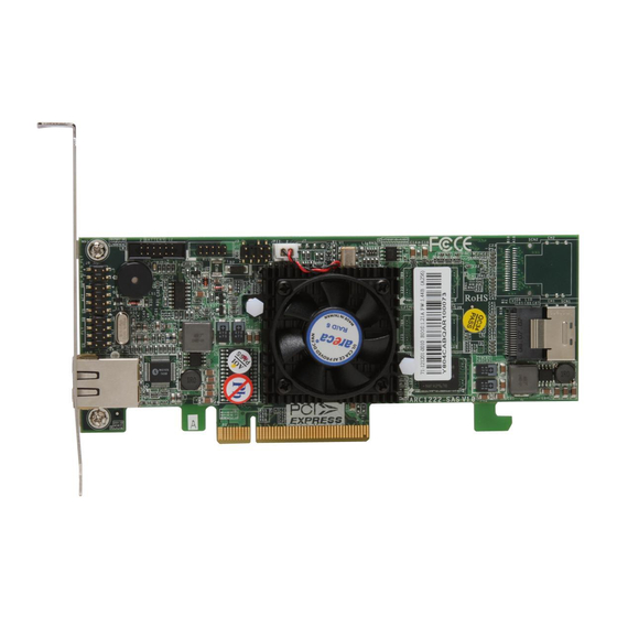
2.2 Board Layout The controller can support a family included 4/8 ports models with 1/2 internal SFF-8087 connectors. This section provides the board layout and connector/jumper for the SAS RAID controller. Figure 2-1, ARC-1212/1222 SAS RAID Controller Connector Type Description 1. - Page 17 The SAS RAID controller can be installed in a universal PCIe slot and requires a motherboard that: ARC-1212/1222 series SAS RAID controller requires: • Comply with the PCIe x8 It can work on the PCIe x1, x4, x8, and x16 signal with x8 or x16 slot M/B.
-
Page 18: Installation
HARDWARE INSTALLATION Warning: High voltages may be found inside computer equipment. Before installing any of the hardware in this package or removing the protective covers of any computer equipment, turn off power switches and disconnect power cords. Do not reconnect the power cords until you have replaced the covers. - Page 19 Press down gently but firmly to ensure that the card is prop- erly seated in the slot, as shown in Figure 2-6. Then, screw the bracket into the computer chassis. ARC-1212/1222 series cards require a PCIe x8 slot. Figure 2-2, Insert SAS RAID controller into a PCIe slot Step 4.
- Page 20 HARDWARE INSTALLATION In the backplane solution, SAS/SATA drives are directly connected to SAS/SATA system backplane. The number of SAS/SATA drives is limited to the number of slots available on the backplane. Step 5. Install SAS Cable This section describes SAS cable how to connect on controller. Figure 2-3, SAS Cable Connect to HD Figure 2-4, SAS Cable Connect to Backplane...
- Page 21 HARDWARE INSTALLATION Step 6. Install the LED Cable (option) The preferred I/O connector for server backplanes is the Min SAS 4i internal connector. This connector has eight signal pins to support four SAS/SATA drives and six pins for the SGPIO (Serial General Purpose Input/Output) side-band signals.
- Page 22 In an existing system: • To install the controller driver into the existing operating system. For the detailed installation procedure, please refer to the Chapter 4, Driver Installation. Note: For lastest release versions of drivers, please download from http://www.areca.com.tw...
-
Page 23: Sas Cables
HARDWARE INSTALLATION Step 12. Install ArcHttp Proxy Server The SAS RAID controller firmware has embedded the web-browser McRAID storage manager. ArcHttp proxy server will launch the web-browser McRAID storage manager. It provides all of the cre- ation, management and monitor SAS RAID controller status. Please refer to the Chapter 5 for the detail ArcHttp Proxy Server Installa- tion. -
Page 24: Internal Min Sas 4I To 4Xsff-8482 Cable
HARDWARE INSTALLATION supports SGPIO header can leverage the SGPIO function on the SAS RAID controller through the sideband cable. The sideband cable is reserved for the backplane with header on Figure 2-5, Internal Min SAS 4i to 4x SATA Cable 2.4.2 Internal Min SAS 4i to 4xSFF-8482 Cable These controllers can be installed in a server RAID enclosure with out a backplane. -
Page 25: Internal Min Sas 4I To Internal Min Sas 4I Cable
HARDWARE INSTALLATION 2.4.3 Internal Min SAS 4i to Internal Min SAS 4i cable The SAS RAID controllers have 1-6 Min SAS 4i internal connec- tors, each of them can support up to four SAS/SATA signals. These adapters can be installed in a server RAID enclosure with Min SAS 4i internal connectors backplane. - Page 26 HARDWARE INSTALLATION Note: A cable for the global indicator comes with your computer system. Cables for the individual drive LEDs may come with a drive cage, or you may need to purchase them. The following diagrams and descriptions describe each type of con- nector.
- Page 27 HARDWARE INSTALLATION Figure 2-8, ARC-1212/1222 Individual LED Indicators con- nector, for each channel drive. B: I C Connector You can also connect the I C interface to a proprietary SAS/SATA backplane enclosure. This can reduce the number of activity LED and/or fault LED cables.
- Page 28 The global fault pin pair connector is the overall fault signals. The global activity pin pair connector is the overall activity signals. The following diagrams show the connector and pin locations. Figure 2-9, ARC-1212/1222 Global Indicator Connector for Computer Case. 2.6 Summary of the installation The flow chart below describes the installation procedures for SAS RAID controllers.
- Page 29 HARDWARE INSTALLATION Configuration Utility Operating System Supported McBIOS RAID Manager OS-Independent McRAID Storage Manager Windows 2000/XP/Server 2003/Vista, (Via Archttp proxy server) Linux, FreeBSD, Solaris and Mac SAP Monitor (Single Admin Portal to Windows 2000/XP/Server 2003/Vista scan for multiple RAID units in the net- work, via ArcHttp proxy server) SNMP Manager Console Integration Windows 2000/XP/Server 2003/Vista...
- Page 30 Before launching the SNMP agent in the sever, you need first to enable the firmware-embedded SNMP community configuration and install Areca SNMP extension agent in your server system. If you need additional information about installation and start-up the function, see the SNMP Operation & Installation section in the Appendix C.
-
Page 31: Mcbios Raid Manager
(after the system BIOS startup screen but before the operating system boots): ARC-1212 PCIEx4 RAID Controller - DRAM: 256(MB) / #Channels: 16 BIOS: V1.17b / Date: 2006-8-07 - F/W: V1.42 / Date: 2007-3-1 Bus/Dev/Fun= 1/0/0, I/0-Port=28000000h, IRQ=9, BIOS=CB00 : 0h No BIOS disk found. -
Page 32: Mcbios Raid Manager
While the desired controller is highlighted, press the Enter key to enter the main menu of the McBIOS RAID manager. I/O Port Addr : 28000000h, F2(Tab): Select Controller, F10: Reboot System Areca Technology Corporation RAID Controller Note: Main Menu... -
Page 33: Configuring Raid Sets And Volume Sets
BIOS CONFIGURATION • Define volume sets, • Modify volume sets, • Modify RAID level/stripe size, • Define pass-through disk drives, • Modify system functions and • Designate drives as hot spares. 3.3 Configuring Raid Sets and Volume Sets You can configure RAID sets and volume sets with McBIOS RAID manager automatically. -
Page 34: Using Quick Volume /Raid Setup Configuration
RAID level, stripe size and capacity of the new volume set. Designating drives as hot spares is also possible in the “Raid Level” selection option. The volume set default settings will Parameter Setting Volume Name ARC-1212-VOL#00 SCSI Channel/SCSI ID/SCSI LUN 0/0/0 Cache Mode Write Back Tag Queuing The default setting values can be changed after configuration is completed. -
Page 35: Using Raid Set/Volume Set Function Method
BIOS CONFIGURATION The capacity for the current volume set is entered after highlighting the desired RAID level and pressing the Enter key. The capacity for the current volume set is displayed. Use the UP and DOWN arrow keys to set the capacity of the volume set and press the Enter key to confirm. - Page 36 BIOS CONFIGURATION Step Action To setup the hot spare (option), choose “Raid Set Function” from the main menu. Select the “Create Hot Spare” and press the Enter key to define the hot spare. Choose “RAID Set Function” from the main menu. Select “Create Raid Set”...
-
Page 37: Main Menu
The main menu shows all functions that are available for executing actions, which is accomplished by clicking on the appropriate link. I/O Port Addr : 28000000h, F2(Tab): Select Controller, F10: Reboot System Areca Technology Corporation RAID Controller Main Menu Quick Volume/Raid Setup... -
Page 38: Quick Volume/Raid Setup
BIOS CONFIGURATION Option Description Quick Volume/Raid Setup Create a default configuration based on the number of physical disk installed Raid Set Function Create a customized RAID set Volume Set Function Create a customized volume set Physical Drives View individual disk information Raid System Function Setup the RAID system configuration Ethernet Configuration... - Page 39 Select “Quick Volume/Raid Setup” from the main menu; all possible RAID level will be displayed on the screen. I/O Port Addr : 28000000h, F2(Tab): Select Controller, F10: Reboot System Areca Technology Corporation RAID Controller Main Menu Quick Volume/Raid Setup...
- Page 40 “Create Volume Set” option in the main menu to define additional volume sets. I/O Port Addr : 28000000h, F2(Tab): Select Controller, F10: Reboot System Areca Technology Corporation RAID Controller Main Menu Available Capacity : 2400.0GB...
- Page 41 BIOS CONFIGURATION I/O Port Addr : 28000000h, F2(Tab): Select Controller, F10: Reboot System Areca Technology Corporation RAID Controller Main Menu Available Capacity : 2400.0GB Quick Volume/Raid Setup Selected Capacity: 2400.0GB Raid Set Function Total 5 Drives Volume Set Function Raid 0...
-
Page 42: Raid Set Function
Available)” for initialization and “No Init (To Rescue Volume)” for recovering the missing RAID set configuration. I/O Port Addr : 28000000h, F2(Tab): Select Controller, F10: Reboot System Areca Technology Corporation RAID Controller Main Menu Available Capacity : 2400.0GB Quick Volume/Raid Setup Selected Capacity: 2400.0GB... -
Page 43: Create Raid Set
Yes option to confirm it. 4. An “Edit The Raid Set Name” dialog box appears. Enter 1 to I/O Port Addr : 28000000h, F2(Tab): Select Controller, F10: Reboot System Areca Technology Corporation RAID Controller Main Menu Quick Volume/Raid Setup... -
Page 44: Delete Raid Set
RAID sets first with the same disk members on each RAID set. The max no. Disk drives per volume set: 8 I/O Port Addr : 28000000h, F2(Tab): Select Controller, F10: Reboot System Areca Technology Corporation RAID Controller Main Menu Quick Volume/Raid Setup... -
Page 45: Expand Raid Set
BIOS CONFIGURATION 3.7.2.3 Expand Raid Set I/O Port Addr : 28000000h, F2(Tab): Select Controller, F10: Reboot System Areca Technology Corporation RAID Controller Main Menu Quick Volume/Raid Setup Raid Set Function Raid Set Function Raid Set Function Volume Set Function Physical Drives... -
Page 46: Migrating
BIOS CONFIGURATION • Migrating I/O Port Addr : 28000000h, F2(Tab): Select Controller, F10: Reboot System Areca Technology Corporation RAID Controller Main Menu Quick Volume/Raid Setup Raid Set Function Raid Set Function Raid Set Function Volume Set Function The Raid Set Information... -
Page 47: Create Hot Spare
“Create Hot Spare” to designate it as a hot spare. The “Create Hot Spare” option gives you the ability to define a global hot spare. I/O Port Addr : 28000000h, F2(Tab): Select Controller, F10: Reboot System Areca Technology Corporation RAID Controller Main Menu Quick Volume/Raid Setup Raid Set Function... -
Page 48: Raid Set Information
BIOS CONFIGURATION I/O Port Addr : 28000000h, F2(Tab): Select Controller, F10: Reboot System Areca Technology Corporation RAID Controller Main Menu Raid Set Function Quick Volume/Raid Setup Create Raid Set Raid Set Function Delete Raid Set Volume Set Function Expand Raid Set... - Page 49 RAID set rather than one volume set using some of the available disks and another volume set using other disks. I/O Port Addr : 28000000h, F2(Tab): Select Controller, F10: Reboot System Areca Technology Corporation RAID Controller Main Menu Quick Volume/Raid Setup Raid Set Function...
-
Page 50: Create Volume Set (0/1/10/3/5/6)
BIOS CONFIGURATION 3.7.3.1 Create Volume Set (0/1/10/3/5/6) I/O Port Addr : 28000000h, F2(Tab): Select Controller, F10: Reboot System Areca Technology Corporation RAID Controller Main Menu Quick Volume/Raid Setup Raid Set Function Volume Set Functions Volume Set Function Volume Set Function... -
Page 51: Volume Name
7. The initialization percentage of volume set will be displayed at the button line. • Volume Name The default volume name will always appear as ARC-1212-VOL #. You can rename the volume set providing it does not exceed the 15 characters limit. -
Page 52: Raid Level
Areca Technology Corporation RAID Controller Main Menu Quick Volume/Raid Setup Raid Set Function Volume Creation Volume Set Function Volume Set Function Physical Drives Volume Name : ARC-1212-VOL # 00 Raid Level Raid System Function Raid Level Ethernet Configuration Capacity : 2400.0GB Select Raid Level... - Page 53 If volume capacity will exceed 2TB, controller will show the "Greater Two TB Volume Support" sub-menu. I/O Port Addr : 28000000h, F2(Tab): Select Controller, F10: Reboot System Areca Technology Corporation RAID Controller Main Menu Greater Two TB Volume Support Quick Volume/Raid Setup...
-
Page 54: Scsi Channel
BIOS CONFIGURATION I/O Port Addr : 28000000h, F2(Tab): Select Controller, F10: Reboot System Areca Technology Corporation RAID Controller Main Menu Quick Volume/Raid Setup Raid Set Function Volume Creation Volume Set Functions Volume Set Function Volume Set Function Volume Name : ARC-1212-VOL#00... -
Page 55: Scsi Lun
BIOS CONFIGURATION I/O Port Addr : 28000000h, F2(Tab): Select Controller, F10: Reboot System Areca Technology Corporation RAID Controller Main Menu Quick Volume/Raid Setup Volume Creation Raid Set Function Volume Set Functions Volume Set Function Volume Set Function Volume Name : ARC-1212-VOL#00... -
Page 56: Tag Queuing
BIOS CONFIGURATION I/O Port Addr : 28000000h, F2(Tab): Select Controller, F10: Reboot System Areca Technology Corporation RAID Controller Main Menu Quick Volume/Raid Setup Volume Creation Raid Set Function Volume Set Functions Volume Set Function Volume Set Function Volume Name : ARC-1212-VOL#00... -
Page 57: Delete Volume Set
ArrowKey Or AZ:Move Cursor, Enter: Select, ESC: Escape, L:Line Draw, X: Redraw Note: ARC-1212 4-port SAS/SATA controller does not support Raid30/50/60. There is no action on this configuration when it is appeared. RAID level 30, 50 and 60 can not support expansion and migration. -
Page 58: Modify Volume Set
BIOS CONFIGURATION I/O Port Addr : 28000000h, F2(Tab): Select Controller, F10: Reboot System Areca Technology Corporation RAID Controller Main Menu Quick Volume/Raid Setup Raid Set Function Volume Set Functions Volume Set Function Volume Set Function Creat Volume Set Physical Drives... -
Page 59: Volume Growth
BIOS CONFIGURATION 3.7.3.4.1 Volume Growth Use “Expand RAID Set” function to add disk to a RAID set. The additional capacity can be used to enlarge the last volume set size or to create another volume set. The “Modify Volume Set” function can support the “Volume Modification”... -
Page 60: Check Volume Set
I/O Port Addr : 28000000h, F2(Tab): Select Controller, F10: Reboot System Areca Technology Corporation RAID Controller Main Menu The Volume Set Information Quick Volume/Raid Setup Volume Set Name : ARC-1212-VOL # 00 Raid Set Function Volume Set Function Volume Set Function Raid Set Name... -
Page 61: Stop Volume Set Check
Areca Technology Corporation RAID Controller Main Menu The Volume Set Information Volume Set Function Quick Volume/Raid Setup Raid Set Function Volume Set Name : ARC-1212-VOL # 00 Create Volume Set Volume Set Function Volume Set Function Raid Set Name : Raid Set # 00... -
Page 62: View Drive Information
SAS RAID controller are listed. Move the cursor to the de- sired drive and press Enter key to view drive information. I/O Port Addr : 28000000h, F2(Tab): Select Controller, F10: Reboot System Areca Technology Corporation RAID Controller Ch01 Main Menu... -
Page 63: Modify A Pass-Through Disk
BIOS CONFIGURATION I/O Port Addr : 28000000h, F2(Tab): Select Controller, F10: Reboot System Areca Technology Corporation RAID Controller Main Menu Quick Volume/Raid Setup Physical Drive Function Raid Set Function Select The Drives Volume Set Function View Drive Information Physical Drive Information Physical Drives E#1Solt#2 : 500.1GB : HDS725050KLA360... -
Page 64: Identify Selected Drive
Indicator will light for physically locating the selected disk when the “Identify Selected Device” is selected. I/O Port Addr : 28000000h, F2(Tab): Select Controller, F10: Reboot System Areca Technology Corporation RAID Controller Main Menu Quick Volume/Raid Setup Physical Drive function... -
Page 65: Mute The Alert Beeper
BIOS CONFIGURATION I/O Port Addr : 28000000h, F2(Tab): Select Controller, F10: Reboot System Areca Technology Corporation RAID Controller Main Menu Quick Volume/Raid Setup Raid Set Function Volume Set Function Physical Drives Raid System Function Raid System Function Ethernet Configuration View System Events... -
Page 66: Change Password
BIOS CONFIGURATION I/O Port Addr : 28000000h, F2(Tab): Select Controller, F10: Reboot System Areca Technology Corporation RAID Controller Raid System Function Main Menu Mute The Alert Beeper Quick Volume/Raid Setup Alert Beeper Setting Alert Beeper Setting Raid Set Function Change Password... -
Page 67: Jbod/Raid Function
User needs to delete the RAID set, when you want to change the option from the RAID to the JBOD function. I/O Port Addr : 28000000h, F2(Tab): Select Controller, F10: Reboot System Areca Technology Corporation RAID Controller Raid System Function Main Menu... -
Page 68: Sata Ncq Support
BIOS CONFIGURATION I/O Port Addr : 28000000h, F2(Tab): Select Controller, F10: Reboot System Areca Technology Corporation RAID Controller Raid System Function Main Menu Background Task Priority Mute The Alert Beeper Quick Volume/Raid Setup Alert Beeper Setting UltraLow(5%) Raid Set Function... -
Page 69: Hdd Read Ahead Cache
Areca RAID controller has included the option for customer to select the disk drives sequentially stagger power up value. The... -
Page 70: Controller Fan Detection
0.4s to 6s per step which powers up one drive. I/O Port Addr : 28000000h, F2(Tab): Select Controller, F10: Reboot System Areca Technology Corporation RAID Controller Raid System Function Main Menu Mute The Alert Beeper... -
Page 71: Auto Activate Raid Set
ArrowKey Or AZ:Move Cursor, Enter: Select, ESC: Escape, L:Line Draw, X: Redraw 3.7.5.11 Capacity Truncation Areca RAID controllers use drive truncation so that drives from different vendors are more likely to be usable as spares for one another. Drive truncation slightly decreases the usable capac- ity of a drive that is used in redundant units. -
Page 72: Ethernet Configuration
No Truncation: It does not truncate the capacity. I/O Port Addr : 28000000h, F2(Tab): Select Controller, F10: Reboot System Areca Technology Corporation RAID Controller Raid System Function Main Menu Mute The Alert Beeper... -
Page 73: Dhcp Function
IP address that does not conflict with other devices on the network. I/O Port Addr : 28000000h, F2(Tab): Select Controller, F10: Reboot System Areca Technology Corporation RAID Controller Main Menu Quick Volume/Raid Setup Raid Set Function... -
Page 74: Http Port Number
Enter key to show the default address setting in the RAID controller. You can then reassign the static IP address of the controller. I/O Port Addr : 28000000h, F2(Tab): Select Controller, F10: Reboot System Areca Technology Corporation RAID Controller Main Menu Quick Volume/Raid Setup Raid Set Function... -
Page 75: Telnet Port Number
Enter key to show the default address setting in the RAID controller. You can then reassign the default “Telnet Port Number” of the controller. I/O Port Addr : 28000000h, F2(Tab): Select Controller, F10: Reboot System Areca Technology Corporation RAID Controller Main Menu Quick Volume/Raid Setup Raid Set Function... -
Page 76: Ethernet Address
Each Ethernet port has its unique Mac address, which is also factory assigned. Usually, Ethernet address is used to uniquely identify a port in the Ethernet network. I/O Port Addr : 28000000h, F2(Tab): Select Controller, F10: Reboot System Areca Technology Corporation RAID Controller Main Menu Quick Volume/Raid Setup Ethernet Configuration... -
Page 77: Clear Events Buffer
BIOS CONFIGURATION 3.7.8 Clear Events Buffer Use this feature to clear the entire events buffer. I/O Port Addr : 28000000h, F2(Tab): Select Controller, F10: Reboot System Areca Technology Corporation RAID Controller Main Menu Quick Volume/Raid Setup Raid Set Function Volume Set Function... -
Page 78: System Information
“System Information” item, then press Enter key. All relevant controller information will be dis- played. I/O Port Addr : 28000000h, F2(Tab): Select Controller, F10: Reboot System Areca Technology Corporation RAID Controller The System Information Main Menu Controller Name... -
Page 79: Driver Installation
If you do not have the software CD disc with the package, contact your local dealers or you can also download the latest version driv- ers for Windows 2000/XP/2003/Vista, Linux, FreeBSD, Solaris and Mac from the Areca web site at http://www.areca.com.tw These driver diskettes are intended for use with new operating... - Page 80 DRIVER INSTALLATION system installations. Determine the correct kernel version and identify which diskette images contain drivers for that kernel. If the driver file ends in .img, create the appropriate driver diskette using “dd” utility. The following steps are required to create the driver diskettes: 1.
-
Page 81: Driver Installation For Windows
DRIVER INSTALLATION 4.2 Driver Installation for Windows The SAS RAID controller can be used with Microsoft Windows 2000/ XP/2003/Vista. The SAS RAID controllers support SCSI Miniport and StorPort Drivers for Windows Server 2003/Vista. 4.2.1 New Storage Device Drivers in Windows 2003/XP-64/Vista The Storport driver is new to Windows Server 2003/XP-64/Vista. - Page 82 8. After Windows scans the hardware and finds the controller, it will display: “Setup will load support for the following mass storage devices:” “ARECA[Windows X86-64 Storport] SATA/SAS PCI RAID Host Controller(RAID6-Engine Inside)”. Press Enter key to continue and copy the driver files. From this point on, simply follow the Microsoft Windows installation procedure.
-
Page 83: Making Volume Sets Available To Windows System
DRIVER INSTALLATION 9. After the installation is completed, reboot the system to load the new driver/operating system. 10. See Chapter 5 in this manual to customize your RAID vol- ume sets using McRAID Storage Manager. 4.2.2.2 Making Volume Sets Available to Windows System When you reboot the system, log in as a system administrator. - Page 84 DRIVER INSTALLATION 1. Follow the instructions in Chapter 2, the Hardware Installation Chapter, to install the controller and connect the disk drives or enclosure. 2. Start the system and then press Tab+F6 to enter the con- troller McBIOS RAID manager. Use the configuration utility to create the RAID set and volume set.
-
Page 85: Making Volume Sets Available To Windows System
DRIVER INSTALLATION the diskette from the drive and click Yes to restart the computer to load the new drivers. 12. See Chapter 5 in this manual for information on customizing your RAID volumes using McRAID Storage Manager. 4.2.3.1 Making Volume Sets Available to Windows System When you reboot the system, log in as a system administrator. -
Page 86: Driver Installation For Linux
3, McBIOS RAID Manager. If you are using a Linux distribution for which there is not a com- piled driver available from Areca, you can copy the source from the SAS software CD or download the source from the Areca website and compile a new driver. -
Page 87: Driver Installation For Freebsd
DRIVER INSTALLATION ed version driver for RedHat, SuSE and other versions of Linux. Please refer to the “readme.txt” file on the included Areca CD or website to make driver diskette and to install driver to the system. 4.4 Driver Installation for FreeBSD This chapter describes how to install the SAS RAID controller driver to FreeBSD. - Page 88 & software. You can install driver& software on your Power Mac G5 or Mac Pro as below: 1. Insert the Areca Mac driver & software CD that came with your Areca SAS RAID controller. 2. Double-click on the following file that resides at <CD-ROM>\ packages\MacOS to add the installer on the Finder.
- Page 89 DRIVER INSTALLATION When you click the archttp, it shows all RAID adapters available on the system and create a individual adapter icon located on left column of the “Archttp Configurations” screen. This adapter icon is for user to launch the selected RAID adapter web browser RAID manager.
-
Page 90: Archttp Proxy Server Installation
ARCHTTP PROXY SERVER INSTALLATION 5. ArcHttp Proxy Server Installation Overview After hardware installation, the SAS/SATA disk drives connected to the SAS RAID controller must be configured and the volume set units initialized before they are ready to use. The user interface for these tasks can be accessed through the built- in configuration that resides in the controller’s firmware. -
Page 91: For Windows
ARCHTTP PROXY SERVER INSTALLATION 5.1 For Windows You must have administrative level permissions to install SAS RAID software. This procedure assumes that the SAS RAID hardware and Windows are installed and operational in your system. Screen captures in this section are taken from a Windows XP instal- lation. -
Page 92: For Linux
RAID controller software. The ArcHttp proxy server is provided on the software CD delivered with SATA card or download from the www.areca.com.tw. The firmware embedded McRAID storage manager can configure and monitor the SATA RAID controller via ArcHttp Proxy Server. - Page 93 ARCHTTP PROXY SERVER INSTALLATION usr/local/sbin). Or (1). Download from the www.areca.com.tw or from the email attachment. 2. You must have administrative level permissions to install SATA RAID controller ArcHttp software. This procedure assumes that the SATA RAID hardware and driver are installed and operational in your system.
-
Page 94: For Freebsd
5.2 For Linux. 5.4 For Solaris 10 X86 Please refer to the “readme.txt“ file on the software CD or website: http://www.areca.com.tw. The next step is the same with Linux. Please see section 5.2 For Linux. 5.5 For Mac OS 10.X The ArcHttp proxy server is provided on the software CD delivered with SATA card or download from the www.areca.com.tw. - Page 95 ARCHTTP PROXY SERVER INSTALLATION 5.6 ArcHttp Configuration The ArcHttp proxy server will automatically assign one additional port for setup its configuration. If you want to change the "archttpsrv.conf" setting up of ArcHttp proxy server configuration, for example: General Configuration, Mail Configuration, and SNMP Configuration, please start web browser http:\\localhost: Cfg Assistant.
- Page 96 Sender Name: Enter the sender name that will be shown in the outgoing mail.Ex: RaidController_1Mail address: Enter the sender email that will be shown in the outgoing mail, but don’t type IP to replace domain name. Ex: RaidController_1@areca.com.tw Account: Enter the valid account if your SMTP mail server need authentication.
- Page 97 ARCHTTP PROXY SERVER INSTALLATION Disable Event Notification: No event notification will be sent. Urgent Error Notification: Send only urgent event Serious Error Notification: Send urgent and serious event Warning Error Notification: Send urgent, serious and warning Event Information Notification: Send all event Notification For No Event: Notify user if no event occurs within 24 hours.
- Page 98 "Generate Test Event" feature to make sure these settings are correct. • Rescan Decive Configuration: Let's assume you've put all Areca RAID adapters to a system. The Archttp scans the RAID adapters on the system and create a individual adapter icon located on left column of the Archttp Configurations screen.
-
Page 99: Web Browser-Based Configuration
WEB BROWSER-BASED CONFIGURATION 6. Web Browser-based Configuration Before using the firmware-based browser McRAID storage manager, do the initial setup and installation of this product. If you need to boot up the operating system from a RAID volume set, you must first create a RAID volume by using McBIOS RAID manager. -
Page 100: Start-Up Mcraid Storage Manager From Windows Local Administration
WEB BROWSER-BASED CONFIGURATION or more and a supported browser. A locally managed system re- quires all of the following components: • A supported Web browser, which should already be installed on the system. • Install ArcHttp proxy server on the SAS RAID system. (Refer to Chapter 5, Archttp Proxy Server Installation) •... - Page 101 Password is “0000” • Start-up McRAID Storage Manager Through Ether- net Port (Out-of-Band) Areca now offers an alternative means of communication for the PCIe RAID controller – Web browser-based McRAID storage man- ager program. User can access the built-in configuration without needing system starting up running the ArcHttp proxy sever.
-
Page 102: Sas Raid Controller Mcraid Storage Manager
WEB BROWSER-BASED CONFIGURATION to the 10/100 RJ45 LAN port. To configure RAID controller on a remote machine, you need to know its IP address. The IP address will default show in McBIOS RAID manager of “Ethernet Configuration” or “System Informa- tion”... -
Page 103: Main Menu
WEB BROWSER-BASED CONFIGURATION 6.3 Main Menu The main menu shows all available functions, accessible by clicking on the appropriate link. Individual Category Description Quick Function Create a default configuration, which is based on the number of physical disks installed; it can modify the volume set Capacity, Raid Level, and Stripe Size. -
Page 104: Create Raid Set
WEB BROWSER-BASED CONFIGURATION Note: In “Quick Create”, your volume set is automatically configured based on the number of disks in your system. Use the “Raid Set Functions” and “Volume Set Functions” if you prefer to customize your volume set, or RAID 30/50/60 volume set. 6.5 Raid Set Functions Use the “Raid Set Function”... -
Page 105: Delete Raid Set
WEB BROWSER-BASED CONFIGURATION Note: To create RAID 30/50/60 volume, you need create multiple RAID sets first with the same disk members on each RAID set. The max no. disk drives per volume set: 8 6.5.2 Delete Raid Set To delete a RAID set, click on the “Deleted Raid Set” link. A “Select The RAID Set To Delete”... -
Page 106: Activate Incomplete Raid Set
WEB BROWSER-BASED CONFIGURATION Press the Yes key to start the expansion on the RAID set. The new additional capacity can be utilized by one or more volume sets. The volume sets associated with this RAID set appear for you to have chance to modify RAID level or stripe size. Follow the instruction presented in the “Modify Volume Set ”... -
Page 107: Create Hot Spare
WEB BROWSER-BASED CONFIGURATION To activate the incomplete the RAID set, click on the “Activate Raid Set” link. A “Select The RAID SET To Activate” screen is displayed showing all RAID sets existing on the current controller. Click the RAID set number to activate in the select column. Click on the “Submit”... -
Page 108: Rescue Raid Set
WEB BROWSER-BASED CONFIGURATION 6.5.7 Rescue Raid Set When the system is powered off in the RAID set update/creation period, the configuration possibly could disappear due to this ab- normal condition. The “RESCUE” function can recover the missing RAID set information. The RAID controller uses the time as the RAID set signature. -
Page 109: Create Volume Set (0/1/10/3/5/6)
TB, because the controller is capable of 64-bit LBA mode. However the operating system itself may not be capable of addressing more than two TB. See Areca website ftp://ftp.areca.com.tw/RaidCards/Docu- ments/Manual_Spec/ Over2TB_050721.ZIP file for details. 6.6.1 Create Volume Set (0/1/10/3/5/6) To create volume set from RAID set system, move the cursor bar to the main menu and click on the “Create Volume Set”... -
Page 110: Volume Name
Support, Initialization Mode, Strip Size, Cache Mode, Tagged Command Queuing, SCSI Channel/SCSI ID/SCSI Lun. • Volume Name The default volume name will always appear as “ARC-1212- VOL”. You can rename the volume set providing it does not exceed the 15 characters limit. •... -
Page 111: Strip Size
WEB BROWSER-BASED CONFIGURATION • Strip Size This parameter sets the size of the stripe written to each disk in a RAID 0, 1, 10, 5, 6, 50 or 60 logical drive. You can set the stripe size to 4 KB, 8 KB, 16 KB, 32 KB, 64 KB, or 128 KB. A larger stripe size produces better read performance, espe- cially if your computer does mostly sequential reads. -
Page 112: Create Raid30/50/60 (Volume Set 30/50/60)
Command Queuing, SCSI Channel/SCSI ID/SCSI Lun. Please refer to above section for details description of each item. Note: ARC-1212 4-port SAS/SATA controller does not support Raid 30/50/60. There is no action on this configuration when it is appeared. RAID level 30, 50 and 60 can support up to eight sub-volumes (RAID set), but it can not support expansion and migration. -
Page 113: Modify Volume Set
WEB BROWSER-BASED CONFIGURATION items in the selected RAID set. Click a volume set number and the “Confirm The Operation” check box and then click the “Sub- mit” button to delete the volume set. 6.6.4 Modify Volume Set To modify a volume set from a RAID set: (1). -
Page 114: Volume Growth
WEB BROWSER-BASED CONFIGURATION 6.6.4.1 Volume Growth Use “Expand RAID Set’ function to add disk to a RAID set. The additional capacity can be used to enlarge the last volume set size or to create another volume set. The “Modify Volume Set” function can support the “Volume Modification”... -
Page 115: Check Volume Set
WEB BROWSER-BASED CONFIGURATION Note: If the volume is RAID level 30, 50, or 60, you can not change the volume to another RAID level. If the volume is RAID level 0, 1, 10, 3, 5, or 6, you can not change the volume to RAID level 30, 50, or 60. -
Page 116: Stop Volume Set Check
WEB BROWSER-BASED CONFIGURATION (1). Click on the “Check Volume Set” link. (2). Click on the volume set from the list that you wish to check. Tick on “Confirm The Operation” and click on the “Submit” button. Use this option to verify the correctness of the redundant data in a volume set. -
Page 117: Modify Pass-Through Disk
WEB BROWSER-BASED CONFIGURATION 6.7.2 Modify Pass-Through Disk Use this option to modify the pass-through disk attribute. The user can modify the Cache Mode, Tagged Command Queuing, and SCSI Channel/ID/LUN on an existing pass-through disk. To modify the pass-through drive attribute from the pass-through drive pool, move the mouse cursor bar and click on the “Modify Pass-Through”... -
Page 118: Delete Pass-Through Disk
WEB BROWSER-BASED CONFIGURATION 6.7.3 Delete Pass-Through Disk To delete a pass-through drive from the pass-through drive pool, move the mouse cursor bar to the main menus and click the “De- lete Pass Through” link. After you complete the selection, mark the check box for “Confirm The Operation”... -
Page 119: System Controls
WEB BROWSER-BASED CONFIGURATION 6.8 System Controls 6.8.1 System Config To set the RAID system function, move the cursor to the main menu and click the “System Controls” link. The “Raid System Function” menu will show all items, then select the desired func- tion. -
Page 120: Hdd Read Ahead Cache
Areca RAID controller has included the option for customer to select the disk drives sequentially stagger power up value. The values can be selected from 0.4s to 6s per step which powers up one drive. -
Page 121: Disk Capacity Truncation Mode
WEB BROWSER-BASED CONFIGURATION • Disk Capacity Truncation Mode Areca RAID controllers use drive truncation so that drives from differing vendors are more likely to be able to be used as spares for each other. Drive truncation slightly decreases the usable capacity of a drive that is used in redundant units. -
Page 122: Alert By Mail Configuration
WEB BROWSER-BASED CONFIGURATION a specific time period (called a lease period) and to eliminate the work necessary to administer a large IP network. To configure the RAID controller Ethernet port, move the cursor bar to the main menu and click on the “System Controls” link. The “System Controls”... -
Page 123: Snmp Configuration
WEB BROWSER-BASED CONFIGURATION 6.8.4 SNMP Configuration To configure the RAID controller SNMP function, click on the “Sys- tem Controls” link. The “System Controls” menu will show avail- able items. Select the “SNMP Configuration” item. This function can only set via web-based configuration. The firmware SNMP agent manager monitors all system events and the SNMP function becomes functional with no agent software required. -
Page 124: Ntp Configuration
WEB BROWSER-BASED CONFIGURATION • SNMP Trap Configurations Enter the SNMP Trap IP Address. • SNMP System Configurations About community, please refer to Appendix C of SNMP com- munity name. The system Contact, Name and Location that will be shown in the outgoing SNMP trap. •... -
Page 125: Time Zone
WEB BROWSER-BASED CONFIGURATION Note: NTP feature works through onboard Ethernet port. So you must make sure that you have connected onboard Ethernet port. • Time Zone Time Zone conveniently runs in the system tray and allows you to easily view the date and time in various locations around the world. -
Page 126: Generate Test Event
WEB BROWSER-BASED CONFIGURATION Select this option to view the system events information: Timer, Device, Event type, Elapse Time and Errors. The RAID control- ler does not have a built-in real time clock. The time information is the relative time from the system time setting. The maximum event no. -
Page 127: Update Firmware
WEB BROWSER-BASED CONFIGURATION The manufacture default password is set to 0000. The password option allows user to set or clear the SAS RAID controller’s password protection feature. Once the password has been set, the user can only monitor and configure the SAS RAID controller by providing the correct password. -
Page 128: Information
WEB BROWSER-BASED CONFIGURATION 6.9 Information 6.9.1 Raid Set Hierarchy Use this feature to view the SAS RAID controller current RAID set, current volume set and physical disk information. The volume state and capacity are also shown in this screen. 6.9.2 System Information To view the SAS RAID controller’s system information, move the mouse cursor to the main menu and click on the “System Infor- mation”... -
Page 129: Hardware Monitor
WEB BROWSER-BASED CONFIGURATION 6.9.3 Hardware Monitor The hardware monitor information of the enclosure attached in this controller is also shown on this screen. -
Page 130: Upgrading Flash Rom Update Process
McRAID Storage manager and nflash DOS utility. New releases of the firmware are available in the form of a DOS file on the shipped CD or Areca website. The files available at the FTP site for each model contain the following files in each version: ARC1212NNNN.BIN Software Binary Code ( “NNNN”... -
Page 131: Upgrading Firmware Through Mcraid Storage Manager
APPENDIX Upgrading Firmware Through McRAID Storage Manager Get the new version firmware for your SAS RAID controller. For example, download the bin file from your OEM’s web site onto the C: drive 1. To upgrade the SAS RAID controller firmware, move the mouse cursor to “Upgrade Firmware”... -
Page 132: Upgrading Firmware Through Nflash Dos Utility
"Raid system Console" on the "System Controls" option. Upgrading Firmware Through nflash DOS Utility Areca now offers an alternative means communication for the SAS RAID controller – Upgrade the all files (BIOS, BOOT, FIRM, MBR0 and Transport) without necessary system starting up to running the ArcHttp proxy server. -
Page 133: Upgrading Firmware Through Cli
Upgrading Firmware Through CLI This Command Line Interface (CLI) provides you to configure and manage the Areca SAS RAID controller components in Windows, Linux, FreeBSD and more environments. The CLI is useful in environments where a graphical user interface (GUI) is not available. -
Page 134: Battery Backup Module (Arc-6120-Bat-Txx)
APPENDIX Appendix B Battery Backup Module (ARC-6120-BAT- xxx) The SAS RAID controller operates using cache memory. The Bat- tery Backup Module is an add-on module that provides power to the SAS RAID controller cache memory in the event of a power failure. -
Page 135: Battery Backup Capacity
APPENDIX 3. Integrators may provide pre-drilled holes in their cabinet for securing the BBM using its three mounting positions. 4.Low profile bracket also provided. Battery Backup Capacity Battery backup capacity is defined as the maximum duration of a power failure for which data in the cache memory can be maintained by the battery. -
Page 136: Changing The Battery Backup Module
APPENDIX Changing the Battery Backup Module At some point, the LI-ION battery will no longer accept a charge properly. LI-ION battery life expectancy is anywhere from ap- proximately 1 to 5 years. 1. Shutdown the operating system properly. Make sure that cache memory has been flushed. - Page 137 APPENDIX Temperature: 0 C to +40 • Humidity: 45-85%, non-condensing • Storage Temperature Temperature: -40 C to 60 • Humidity: 45-85%, non-condensing Electrical • Input Voltage +3.6VDC • On Board Battery Capacity 1100mAH (1*1100mAH)
-
Page 138: Snmp Operation & Installation
APPENDIX Appendix C SNMP Operation & Installation Overview The McRAID storage manager includes a firmware-embedded Sim- ple Network Management Protocol (SNMP) agent and SNMP Exten- sion Agent for the SAS RAID controller. An SNMP-based manage- ment application (also known as an SNMP manager) can monitor the disk array. - Page 139 APPENDIX MIB Compilation and Definition File Creation Before the manager application accesses the RAID controller, it is necessary to integrate the MIB into the management application’s database of events and status indicator codes. This process is known as compiling the MIB into the application. This process is highly vendor-specific and should be well-covered in the User’s Guide of your SNMP application.
- Page 140 RAID hardware and Windows are both installed and operational in your system. To enable the SNMP agent for Windows, configure Windows for TCP/IP and SNMP services. The Areca SNMP extension agent file is ARCSNMP.DLL. Screen captures in this section are taken from a Windows XP instal- lation.
- Page 141 SNMP service first.) 3. Click on the “Setup.exe” file then the welcome screen appears. 4. Click the “Next” button and then the “Ready Install the Pro- gram” screen will appear. Follow the on-screen prompts to com- plete Areca SNMP extension agent installation.
- Page 142 APPENDIX 5. A Progress bar appears that measures the progress of the Areca SNMP extension agent setup. When this screen completes, you have completed the Areca SNMP extension agent setup. 6. After a successful installation, the “Setup Complete” dialog box of the installation program is displayed.
- Page 143 APPENDIX SNMP Community Configurations Please refer to the community name in this appendix. SNMP Trap Notification Configurations The "Community Name" should be the same as firmware- embedded SNMP Community. The "SNMP Trap Notification Configurations" include level 1: Serious, level 2: Error, level 3: Warning and level 4: Information.
- Page 144 Linux are installed and operational in your system. For the SNMP extension agent installation for Linux procedure, please refer to <CD-ROM>\packages\Linux\SNMP\Readme or download from areca.com.tw SNMP Extension Agent Installation for FreeBSD You must have administrative level permission to install SAS RAID software.
-
Page 145: Event Notification Configurations
APPENDIX Appendix D Event Notification Configurations The controller classifies disk array events into four levels depending on their severity. These include level 1: Urgent, level 2: Serious, level 3: Warning and level 4: Information. The level 4 covers notification events such as initialization of the controller and initiation of the rebuilding process;... -
Page 146: Volume Event
APPENDIX PassThrough Disk Inform Pass Through Disk Created created PassThrough Disk Inform Pass Through Disk Modified modified PassThrough Disk Inform Pass Through Disk Deleted deleted B. Volume Event Event Level Meaning Action Start Initialize Warning Volume initialization has started Start Rebuilding Warning Volume rebuilding has started Start Migrating... -
Page 147: Raid Set Event
APPENDIX C. RAID Set Event Event Level Meaning Action Create RaidSet Warning New RAID set created Delete RaidSet Warning Raidset deleted Expand RaidSet Warning Raidset expanded Rebuild RaidSet Warning Raidset rebuilding RaidSet Urgent Raidset degraded Replace HDD Degraded D. Hardware Monitor Event Event Level Meaning... - Page 148 APPENDIX Telnet Log Serious a Telnet login detected InVT100 Log In Serious a VT100 login detected API Log In Serious a API login detected Lost Rebuilding/ Urgent Some rebuilding/ Reinserted the missing member MigrationLBA migration raidset disk back, controller will member disks continued the incompleted missing before power...
-
Page 149: Raid Concept
APPENDIX Appendix E RAID Concept RAID Set A RAID set is a group of disks connected to a SAS RAID control- ler. A RAID set contains one or more volume sets. The RAID set itself does not define the RAID level (0, 1, 10, 3, 5, 6, 30, 50 60, etc);... -
Page 150: Ease Of Use Features
RAID set. Therefore, if a server fails, the RAID set disk drives can be moved to another server with an Areca SAS/SATA RAID controllers and the disks can be inserted in any order. Online Capacity Expansion •... - Page 151 APPENDIX on the existing volume sets (residing on the newly expanded RAID set) is redistributed evenly across all the disks. A contigu- ous block of unused capacity is made available on the RAID set. The unused capacity can be used to create additional volume sets.
- Page 152 Online RAID Level and Stripe Size Migration • For those who wish to later upgrade to any RAID capabilities, a system with Areca online RAID level/stripe size migration allows a simplified upgrade to any supported RAID level without having to reinstall the operating system.
-
Page 153: Online Volume Expansion
APPENDIX tion is completed, the volume set transitions to degraded mode. If a global hot spare is present, then it further transitions to rebuilding state. Online Volume Expansion • Performing a volume expansion on the controller is the process of growing only the size of the latest volume. A more flexible op- tion is for the array to concatenate an additional drive into the RAID set and then expand the volumes on the fly. -
Page 154: Hot-Swap Disk Drive Support
APPENDIX automatically take its place and he data previously located on the failed drive is reconstructed on the Global Hot Spare. For this feature to work properly, the global hot spare must have at least the same capacity as the drive it replaces. Global Hot Spares only work with RAID level 1, 10, 3, 5, 6, 30, 50, or 60 volume set. -
Page 155: Auto Rebuilding
APPENDIX The Hot-Swap function can be used to rebuild disk drives in ar- rays with data redundancy such as RAID level 1, 10, 3, 5, 6, 30, 50 and 60. Auto Rebuilding • If a hot spare is available, the rebuild starts automatically when a drive fails. -
Page 156: High Reliability
APPENDIX high array performance, specify an Ultra Low value. Like volume initialization, after a volume rebuilds, it does not require a sys- tem reboot. High Reliability Hard Drive Failure Prediction • In an effort to help users avoid data loss, disk manufacturers are now incorporating logic into their drives that acts as an "early warning system"... -
Page 157: Consistency Check
APPENDIX In the event of an unrecoverable read error, the error will be re- ported to the host and the location will be flagged as being po- tentially defective. A subsequent write to that location will initiate a sector test and relocation should that location prove to have a defect. -
Page 158: Recovery Rom
APPENDIX batteries protect data in a failed server for up to three or four days, depending on the size of the memory module. Under nor- mal operating conditions, the batteries last for three years before replacement is necessary. Recovery ROM •... -
Page 159: Understanding Raid
APPENDIX Appendix F Understanding RAID RAID is an acronym for Redundant Array of Independent Disks. It is an array of multiple independent hard disk drives that provides high performance and fault tolerance. The SAS RAID control- ler implements several levels of the Berkeley RAID technology. An appropriate RAID level is selected when the volume sets are defined or created. - Page 160 APPENDIX RAID 1 RAID 1 is also known as “disk mirroring”; data written on one disk drive is simultaneously written to another disk drive. Read performance will be enhanced if the array controller can, in paral- lel, access both members of a mirrored pair. During writes, there will be a minor performance penalty when compared to writing to a single disk.
-
Page 161: Raid 3
A, B, C, D and E. In this configura- tion, each strip is mirrored on an adjacent disk with wrap-around. Areca RAID 10 offers a little more flexibility in choosing the num- ber of disks that can be used to constitute an array. The number can be even or odd. - Page 162 APPENDIX RAID 5 RAID 5 is sometimes called striping with parity at byte level. In RAID 5, the parity information is written to all of the drives in the controllers rather than being concentrated on a dedicated parity disk. If one drive in the system fails, the parity information can be used to reconstruct the data from that drive.
-
Page 163: Raid X0
APPENDIX RAID 6 RAID 6 provides the highest reliability. It is similar to RAID 5, but it performs two different parity computations or the same compu- tation on overlapping subsets of the data. RAID 6 can offer fault tolerance greater than RAID 1 or RAID 5 but only consumes the capacity of 2 disk drives for distributed parity data. -
Page 164: Jbod
APPENDIX Important RAID level 30, 50 and 60 can support up to eight sub-Vol- umes (RAID set). If the volume is RAID level 30, 50, or 60, you cannot change the volume to another RAID level. If the volume is RAID level 0, 1, 10, 3, 5, or 6, you cannot change the volume to RAID level 30, 50, or 60. - Page 165 APPENDIX Summary of RAID Levels RAID subsystem supports RAID Level 0, 1, 10, 3, 5, 6, 30, 50 and 60. The following table provides a summary of RAID levels. Features and Performance RAID Description Min. Disks Data Level requirement Reliability Also known as stripping No data Data distributed across multiple drives...
- Page 166 APPENDIX As RAID level 5, but with additional Two-disk failure independently computed redundant information RAID 30 is a combination multiple Up to one disk failure RAID 3 volume sets with RAID 0 in each sub-volume (striping) RAID 50 is a combination multiple Up to one disk failure RAID 5 volume sets with RAID 0 in each sub-volume...
- Page 167 HISTORY Version History Revision Page Description p.133 Deleted note description...