Download
1 / 38
380 likes | 514 Views
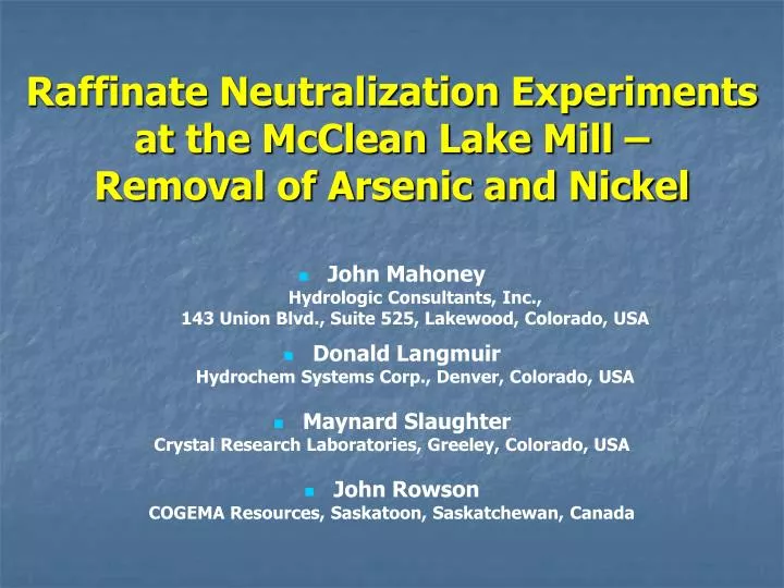
Raffinate Neutralization Experiments at the McClean Lake Mill – Removal of Arsenic and Nickel. John Mahoney Hydrologic Consultants, Inc., 143 Union Blvd., Suite 525, Lakewood, Colorado, USA Donald Langmuir Hydrochem Systems Corp., Denver, Colorado, USA

E N D
Raffinate Neutralization Experiments at the McClean Lake Mill –Removal of Arsenic and Nickel • John Mahoney Hydrologic Consultants, Inc., 143 Union Blvd., Suite 525, Lakewood, Colorado, USA • Donald Langmuir Hydrochem Systems Corp., Denver, Colorado, USA • Maynard Slaughter Crystal Research Laboratories, Greeley, Colorado, USA • John Rowson COGEMA Resources, Saskatoon, Saskatchewan, Canada
Overview • Arsenic and Nickel Bearing Uranium Ores • Tailings disposal issues • Raffinate 300-700 mg/L As, 200-500 mg/L Ni, pH~1.0 • Diffusion of As into Fox Lake required As and Ni in tailings pore waters be ~ 1 mg/L
Tailings Optimization and Validation • License Application - Initial model based on mineral precipitation (scorodite) and surface complexation of As on Hydrous Ferric Oxide (Langmuir et al., 1999) • Demonstrated that As < 1 mg/L was possible • Tailings Optimization and Validation Program (TOVP) ongoing studies to • Verify and improve process, • Monitor tailings management facility, and • Validate model assumptions
Tailings Neutralization • Tailings neutralization circuit increases Fe:As > 3 • Ferric sulfate is used to increase Fe:As • Neutralization by slaked lime • Two stage process • pH 4 first tank • pH 7 - 8 second tank
Raffinate Fe (SO ) 2 4 3 CaO (pH 8) Tailings CaO (pH 4) BaCl 2 Flocculant pH pH NEUTRALIZATION TANKS MIXING TANK THICKENER Process Air to TMF 24 hour metallurgical composite sample Tailings Neutralization Circuit
Raffinate Neutralization Experiments • Plant raffinate spiked ~ 700 mg/L As, 500 mg/L Ni • Ferric sulfate added • Dry Lime (CaO), slaked lime (Ca(OH)2, or NaOH • Some experiments included leach residue • Short duration to simulate residence times in Neutralization Circuit • Filtered samples - solution analyses • Solids air dried -mineralogical analysis • Raffinate 2 series, Redox measurements, single beaker experiments
Neutralization Tests at pH Values of 2.2 to 7.4 (right to left) Beaker on Far Left is Slurried Lime)
Mineralogy Studies • X-ray diffraction • SEM with Energy Dispersive Spectrometry • Chemical analysis, mainly XRF, Fe(II) • EXAFS- Canadian Light Source and Argonne APL • Microprobe (electron beam, synchronous radiation) • Quantitative mineralogy - XRD, analysis
Single Beaker Tests • Raffinate 2 • Separated mineral precipitates rather than accumulate all precipitates • Enhanced X-ray diffraction determinations • Initial volume of solution ~ 5 L • Three solution samples collected • Four solid samples
Saturation Indices(based upon As (V) and Fe(III) concentrations)
Eh-pH diagram for the systems Fe – As – O – H based upon stabilities of scorodite and ferrihydrite using speciatedAs and Fe data from the Raffinate 2 neutralization experiments
Geochemical Model • PHREEQC used • Ferric arsenate complexes included in database • Disequilibrium steps included to explain removal of Ni at low pH • Force fit • Simple mineral precipitation reactions • Gypsum – Sulfate [CaSO4 • 2H2O] • Scorodite (Ksp adjusted) – Fe and As to pH ~5 [FeAsO4 • 2H2O] • Ferrihydrite/Green Rust II- IronFe(OH)3 /Fe3(OH)8 • Theophrastite – Nickel[Ni(OH)2] • Annabergite – Nickel [Ni3(AsO4)2• 8H2O] • Basaluminite – Aluminum [Al4SO4 (OH)10 • nH2O]
Tailings Neutralization ProcessInitial Reaction McClean Lake Operation Solution pH 1.5 Analyte (mg/L) (% prec.) Al As Fe Ni Si 420 732 2,400 560 260 0.0 0.0 0.0 0.0 0.0
Tailings Neutralization ProcesspH Gradient McClean Lake Operation Solution pH 1.5 Analyte (mg/L) (% prec.) Al As Fe Ni Si 420 659 2,328 532 260 0.0 ~10 ~3 ~5 0.0
Tailings Neutralization ProcessBulk Neutralization McClean Lake Operation Solution pH 2.2 Analyte (mg/L) (% prec.) Al As Fe Ni Si 420 150 1,600 500 260 0.0 79.5 33.3 10.7 0.0
Tailings Neutralization ProcessBulk Neutralization McClean Lake Operation Solution pH 4.0 Analyte (mg/L) (% prec.) Al As Fe Ni Si 290 0.5 570 450 140 31.0 99.9 76.3 19.6 46.2
Tailings Neutralization ProcessBulk Neutralization McClean Lake Operation Solution pH 6.1 Analyte (mg/L) (% prec.) Al As Fe Ni Si 0.5 0.08 340 250 17 99.9 100.0 85.8 55.4 93.5
Tailings Neutralization ProcessBulk Neutralization McClean Lake Operation Solution pH 7.4 Analyte (mg/L) (% prec.) Al As Fe Ni Si 0.5 0.06 2.2 1.3 3.2 99.9 100.0 99.9 99.8 98.8
Tailings Neutralization ProcessAging McClean Lake Operation Solution pH 7.4 Analyte (mg/L) (% prec.) Al As Fe Ni Si 0.5 0.06 2.2 1.3 3.2 99.9 100.0 99.9 99.8 98.8
RAFFINATE pH = 1.5 pe = 11.88 As = 747 mg/L Ni = 571 mg/L Fe = 2,450 mg/L EQUILIBRATE pH = 7 Ni3(AsO4)2•8H2O FERRIHYDRITE SOLUTION 11 pH = 7 As = 291 mg/L Ni = 35.8 mg/L Fe = 554 mg/L Flow Diagram MIX RAFFINATE SOLUTION 11 10% 90% EQUILIBRATE pH = 2.18 SCORODITE GYPSUM MODEL SOLUTION 6-1 pH = 2.18 pe = 11.7 As = 64.7 mg/L Ni = 518 mg/L Fe = 1,830 mg/L
Conclusions • Scorodite is dominant As - bearing phase • Balance between relatively stable scorodite and less stable ferrihydrite • Adjustments to Ksp produce best fit • Precipitation stops by pH ~ 5 • As concentrations < 1 mg/L • Little or no evidence of As sorption process • Disequilibrium removes some nickel • Nickel mainly in theophrastite • Model concentrations higher than measured • Sorption may also play a role