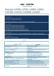
Beosound 3000 Type 2671-2680 .pdf - abo - center
Beosound 3000 Type 2671-2680 .pdf - abo - center
Beosound 3000 Type 2671-2680 .pdf - abo - center

Create successful ePaper yourself
Turn your PDF publications into a flip-book with our unique Google optimized e-Paper software.
BeoSound <strong>3000</strong><br />
<strong>Type</strong> <strong>2671</strong>, 2672, 2673, 2674, 2675, 2676, 2677, <strong>2680</strong><br />
ABO-CENTER v/HENRIKSENS ELEKTRONIK<br />
Service Manual<br />
English, German, French, Italian, Spanish<br />
illustration
Survey of modules<br />
1.1<br />
2 Interface f/µPH8 .................................................. diagram E<br />
page 2.14<br />
18 Headphone ........................................................ diagram G<br />
page 2.17<br />
3 µPH8 Microcomputer ......................................... diagram E<br />
page 2.14<br />
20 IR receiver and left door sensor ...................... diagram F, J<br />
page 2.15, 2.21<br />
ABO-CENTER v/HENRIKSENS ELEKTRONIK<br />
5 Display ............................................................ diagram F, M<br />
page 2.15, 2.25<br />
21 Door sensor right .................................................diagram J<br />
page 2.21<br />
9 Light and motor control .................................... diagram F<br />
page 2.15<br />
28 Light supply ........................................................ diagram F<br />
page 2.15<br />
12 Power Supply, Input select & Pre-amp. .....diagram G, H, I<br />
page 2.17, 2.18, 2.19<br />
86 Tuner-FM/AM-RDS-Stereo decoder ...... diagram A, B, C, D<br />
page 2.9, 2.10, 2.11, 2.12<br />
14 Master Link Audio interface ............................. diagram H<br />
page 2.18<br />
89 Interface f/CD PRO MKI ......................................diagram K<br />
page 2.23<br />
15 Transformer .......................................................... diagram I<br />
page 2.19<br />
99 CD PRO MKI ........................................................ diagram L<br />
page 2.24<br />
9 90*/99<br />
87*/<br />
89<br />
28<br />
5<br />
20<br />
18<br />
21<br />
3<br />
2<br />
15<br />
14<br />
12<br />
86<br />
* for CD PRO MKII
1.2 Specification guidelines<br />
SPECIFICATION GUIDELINES FOR SERVICE USE BeoSound <strong>3000</strong><br />
With FM, AM and RDS<br />
<strong>Type</strong> <strong>2671</strong> EU (230V)<br />
<strong>Type</strong> 2672 GB (240V)<br />
<strong>Type</strong> 2673 USA-CDN (120V)<br />
<strong>Type</strong> 2674 J (100V)<br />
<strong>Type</strong> 2675 AUS (240V)<br />
<strong>Type</strong> 2676 TWN (120V)<br />
<strong>Type</strong> 2677 KOR (220V)<br />
<strong>Type</strong> <strong>2680</strong> LAT (230V)<br />
ABO-CENTER v/HENRIKSENS ELEKTRONIK<br />
Preamplifier section<br />
Total harmonic distortion + Noise R,L<br />
Response vs. frequency:<br />
AUX in<br />
Input sensitivity/impedance<br />
AUX<br />
Input impedance, AUX<br />
Max. input signal, AUX<br />
Signal-to-noise ratio:<br />
AUX, A-weighted<br />
Channel separation 10kHz, AUX<br />
Channel unballance<br />
Bass control at 100Hz<br />
Treble control at 10kHz<br />
Output:<br />
Source seperation<br />
Tone regulation Bass, 100 Hz<br />
Tone regulation Treble 10 kHz<br />
Headphones<br />
< 0.1%/1 kHz<br />
20-20,000Hz ±1dB<br />
200 mV<br />
>22 kΩ<br />
2.0 V<br />
>80 dB<br />
>60 dB<br />
±1.5 dB<br />
±9 dB<br />
±9 dB<br />
>65 dB<br />
9.0 dB ± 2 dB<br />
9.0 dB ± 2 dB<br />
3.5 V / 235 Ω<br />
Tuner, FM section<br />
FM range (50 kHz grid)<br />
87.5-108 MHz<br />
FM range for type 2674 - Japan<br />
76-90 MHz<br />
FM aerial impedance<br />
75 Ω<br />
Usable sensitivity mono 14 dBf - 1.4 µV<br />
Usable sensitivity stereo 19 dBf - 2.5 µV<br />
50 dB quieting sensitivity mono 21 dBf - 2.5 µV<br />
50 dB quieting sensitivity stereo 40 dBf - 28 µV<br />
Signal-to-noise ratio mono<br />
68 dB<br />
Signal-to-noise ratio stereo<br />
62 dB<br />
Frequency response stereo<br />
30 - 15,000 Hz +1/-3 dB<br />
THD + noise mono 0.63 %<br />
THD + noise stereo 0.6 %<br />
Intermodulation distortion stereo<br />
50 dB<br />
Stereo channel separation<br />
35 dB<br />
Subcarrier product rejection<br />
50 dB, stereo<br />
Tuner, AM section<br />
AM range EU (9 kHz grid)<br />
GB (9 kHz grid)<br />
USA MW (10 kHz grid)<br />
Japan MW (9 kHz grid)<br />
AUS MW (9 kHz grid)<br />
Taiwan MW (9 kHz grid)<br />
Korea MW (9 kHz grid)<br />
LW 153 - 279 kHz<br />
MW 522 - 1611 kHz<br />
LW 153 - 279 kHz<br />
MW 522 - 1611 kHz<br />
520 kHz - 1710 kHz<br />
522 kHz - 1629 kHz<br />
522 kHz - 1611 kHz<br />
522 kHz - 1611 kHz<br />
522 kHz - 1611 kHz<br />
LW sensitivity 20 dB S/N ratio<br />
80 - 72 dBµV/m (10 - 4 mV/m) TYP 4mV/meter<br />
MW sensitivity 20 dB S/N ratio<br />
68 - 60 dBµV/m (2.5 - 1mV/m) TYP 2mV/meter<br />
Number of programmes 60<br />
IR Operation<br />
Beo4
Specification guidelines<br />
1.3<br />
CD player<br />
CD, disc types 12 cm (5”), 8 cm (3”)<br />
Frequency response<br />
20 - 20,000 Hz ±1 dB<br />
SNR (digital zero)<br />
>96 dB / 101 dB A-weighted<br />
Dynamic range<br />
>98 dB<br />
Channel difference<br />
±0.3 dB<br />
D/A converter<br />
Bitstream + Analog filter<br />
ABO-CENTER v/HENRIKSENS ELEKTRONIK<br />
Dimensions<br />
W x H x D / Weight<br />
Cabinet finish<br />
Power consumption<br />
32 x 36 x 16 cm / 7 kg<br />
Black / aluminium<br />
Typical 23 watts / stand-by 3 watts<br />
Accessories<br />
<strong>Type</strong> 2051<br />
Stand, silver, black, blue, green, red<br />
<strong>Type</strong> 2052<br />
Center wall bracket, black<br />
<strong>Type</strong> 2087<br />
System wall bracket, black<br />
V-antenna with coax cable 8720039<br />
AM loop antenna 8720043<br />
Connections<br />
Master Link Pin 1 Data- -0.25V<br />
Pin 2 Data+ +0.25V<br />
Pin 3 ML sence 0-5V<br />
Pin 4-10 N.C.<br />
Pin 11 Supply voltage -7V > -15V, stand-by -3V > -15V<br />
Pin 12 Supply voltage 7V > 15V, stand-by 3V > 15V<br />
Pin 13 Audio L-<br />
1V bal., Rin 2.2MΩ, Rout 75Ω<br />
Pin 14 Audio L+<br />
1V bal., Rin 2.2MΩ, Rout 75Ω<br />
Pin 15 Audio R-<br />
1V bal., Rin 2.2MΩ, Rout 75Ω<br />
Pin 16 Audio R+<br />
1V bal., Rin 2.2MΩ, Rout 75Ω<br />
Audio Aux Link Pin 1 Audio L out 1V RMS, Rout 1KΩ<br />
Pin 2 GND<br />
Pin 3 Audio L in 0.25V RMS to 2V RMS, Rin 47KΩ<br />
Pin 4 Audio R out 1V RMS, Rout 1KΩ<br />
Pin 5 Audio R in 0.25V RMS to 2V RMS, Rin 47KΩ<br />
Pin 6-7 Not used<br />
Power Link<br />
Headphones<br />
Power up (ON = >2.7V -1mA)<br />
Pin 2 Signal GND<br />
Pin 3 Audio L out 0V to 2V RMS<br />
Pin 4 Speaker ON (ON = >2.7V -1mA)<br />
Pin 5 Audio R out 0V to 2V RMS<br />
Pin 6 Datalink out (High = >4V, Low =
1.4 Wiring of transformer<br />
Wiring of transformer, PCB15<br />
<strong>Type</strong> <strong>2671</strong>, 2677, <strong>2680</strong><br />
EU, LAT 230V~<br />
KOR 220V~<br />
1B<br />
T1p<br />
16<br />
15<br />
12<br />
100V<br />
1<br />
120V<br />
3<br />
14<br />
240V<br />
230V<br />
L1p<br />
0.4mH<br />
1C<br />
C13p<br />
1000µ<br />
D10<br />
1C<br />
TF1<br />
1C<br />
2<br />
4<br />
8<br />
6<br />
11<br />
10<br />
120V<br />
230V<br />
100V<br />
120V<br />
D9<br />
1C<br />
7<br />
5<br />
13<br />
9<br />
<strong>Type</strong> 2672, 2675<br />
GB, AUS 240V~<br />
T1p<br />
1B<br />
16<br />
15<br />
1<br />
12<br />
100V<br />
120V<br />
3<br />
14<br />
240V<br />
240V<br />
L1p<br />
0.4mH<br />
1C<br />
ABO-CENTER v/HENRIKSENS ELEKTRONIK<br />
C13p<br />
1000µ<br />
TF1<br />
1C<br />
2<br />
4<br />
8<br />
11<br />
10<br />
120V<br />
230V<br />
100V<br />
120V<br />
D10<br />
1C<br />
6<br />
D9<br />
1C<br />
7<br />
5<br />
13<br />
9
Wiring of transformer<br />
1.5<br />
<strong>Type</strong> 2673, 2676<br />
USA-CDN, TWN 120V~<br />
T1p<br />
1B<br />
16<br />
15<br />
1<br />
12<br />
100V<br />
120V<br />
3<br />
14<br />
240V<br />
120V<br />
R1p<br />
3M3<br />
1B<br />
L1p<br />
0.4mH<br />
1C<br />
C13p<br />
1000µ<br />
D10<br />
1C<br />
D9<br />
1C<br />
TF1<br />
1C<br />
2<br />
4<br />
8<br />
6<br />
7<br />
11<br />
10<br />
120V<br />
230V<br />
100V<br />
120V<br />
5<br />
13<br />
9<br />
<strong>Type</strong> 2674<br />
JPN 100V~<br />
1B<br />
T1p<br />
16<br />
15<br />
1<br />
12<br />
3<br />
14<br />
240V<br />
100V<br />
L1p<br />
0.4mH<br />
1C<br />
ABO-CENTER v/HENRIKSENS ELEKTRONIK<br />
100V<br />
120V<br />
C13p<br />
1000µ<br />
D10<br />
1C<br />
TF1<br />
1C<br />
2<br />
4<br />
8<br />
6<br />
11<br />
10<br />
120V<br />
230V<br />
100V<br />
120V<br />
D9<br />
1C<br />
7<br />
5<br />
13<br />
9
1.6 Brief operation guide<br />
Brief operation guide<br />
For more detailed operation see<br />
User’s guide<br />
Tune in radio stations<br />
RADIO Press RADIO to switch<br />
on the radio<br />
Switch on the radio<br />
RADIO Press RADIO to switch<br />
on the radio<br />
TUNE<br />
FM ?<br />
m<br />
p<br />
PLAY<br />
FM 88.9<br />
m<br />
p<br />
0 – 9<br />
Press TUNE to access the<br />
tuning function. FM ?<br />
appears<br />
Switches from FM to<br />
AM, or vice versa<br />
Press PLAY to select AM<br />
or FM. FM or AM and<br />
the current frequency<br />
appears<br />
Press to search for a<br />
radio station – up or<br />
down the frequency<br />
band<br />
Or, key in the exact<br />
frequency<br />
0 – 9<br />
Use the number keys to<br />
select a stored station<br />
m<br />
Step through all stored<br />
p<br />
stations<br />
•<br />
Switch to standby<br />
r<br />
Adjust the volume up or<br />
u<br />
down<br />
MUTE Silences the speakers<br />
immediately. Press again<br />
to recall the sound<br />
Note: Pressing 0 will swap between present and<br />
previous radio station<br />
PLAY<br />
FINE 0<br />
m<br />
p<br />
PLAY<br />
STEREO ?<br />
m<br />
p<br />
Press PLAY to accept*.<br />
FINE 0 appears<br />
Press to fine tune, if<br />
necessary<br />
Press PLAY to accept.<br />
STEREO ? appears<br />
Switches from STEREO<br />
to MONO<br />
Play a CD<br />
CD<br />
0 – 9<br />
m<br />
p<br />
Plays the CD in the<br />
compartment<br />
Plays specific track<br />
numbers<br />
Plays the next track<br />
Plays the previous track<br />
PLAY<br />
P 15 ?<br />
m<br />
p<br />
0 – 9<br />
PLAY<br />
STORED<br />
Press PLAY to accept –<br />
the first available<br />
program number<br />
appears<br />
Press to switch to a<br />
different program<br />
number<br />
Or, key in the program<br />
number you want<br />
Press PLAY to store the<br />
station on the displayed<br />
program number.<br />
STORED appears,<br />
indicating that the<br />
station is stored<br />
STOP<br />
PLAY<br />
n<br />
l<br />
ABO-CENTER v/HENRIKSENS ELEKTRONIK<br />
Pauses playing<br />
Resumes playing<br />
Searches forwards on<br />
the CD<br />
Searches backwards on<br />
the CD<br />
Keep the button pressed<br />
down until you have<br />
reached the point you<br />
want<br />
*Note: When the requested station is found, you<br />
can skip the fine tune and stereo/mono selection<br />
by pressing STORE instead of PLAY. Now just enter<br />
a program number and press PLAY or STORE to<br />
store the station.
Brief operation guide<br />
1.7<br />
Set the built-in clock<br />
Using the Beo4<br />
CLOCK<br />
14 : 45<br />
Press CLOCK to access<br />
the clock function. The<br />
time appears<br />
RADIO<br />
CD<br />
Turns on the radio<br />
Starts the CD player<br />
m<br />
p<br />
0 – 9<br />
PLAY<br />
23 AUG<br />
m<br />
p<br />
PLAY<br />
2000<br />
Press to change to the<br />
exact time, if necessary<br />
Alternatively key in the<br />
exact time<br />
Press PLAY to accept.<br />
The date appears<br />
Press to change the date,<br />
if necessary<br />
Press PLAY to accept.<br />
The year appears<br />
ABO-CENTER v/HENRIKSENS ELEKTRONIK<br />
m<br />
or<br />
p<br />
n<br />
or<br />
l<br />
STOP<br />
Press to step through<br />
your radio programs or<br />
tracks on a CD<br />
Alternatively, key in the<br />
exact number, using the<br />
number keys<br />
Searches through a CD<br />
Searches backwards<br />
through a CD<br />
Pauses playback any time<br />
m<br />
p<br />
Press to change the year,<br />
if necessary<br />
GO<br />
Press to resume<br />
playback<br />
PLAY<br />
STORE ?<br />
STORE<br />
STORED<br />
Press PLAY to accept.<br />
STORE ? appears<br />
Press STORE to store the<br />
new setting.<br />
STORED appears<br />
r<br />
u<br />
•<br />
Raises the volume<br />
Lowers the volume<br />
Switches off<br />
Option programming<br />
For the Beo4 terminal the key sequence is the following:<br />
•<br />
then<br />
LIST<br />
Press and hold<br />
Press to access the setup function. The Beo4 display reads [OPTION?] - let go of<br />
both buttons<br />
GO<br />
Press to access Option-programming<br />
LIST<br />
then<br />
1<br />
Press to display [V.OPT] CTV, or<br />
[A.OPT]<br />
[L.OPT]<br />
audio, or<br />
link room products<br />
Key in the number of the approiate Option, e.g. 1<br />
The digit sequence to be used depends on the setup.<br />
Option 0 = No IR reception<br />
Option 1 = Two IR-eyes in the same main room<br />
Option 2 = One IR-eye in the main room
2.1 Explanation of diagram<br />
Explanation of diagram<br />
<strong>Type</strong> numbers of transistors and ICs are indicated on the diagrams. If the position<br />
is followed by an asterisk the spare part number must always be used because the<br />
component in question has been specially selected, e.g. TR102*.<br />
ABO-CENTER v/HENRIKSENS ELEKTRONIK<br />
Component print and coordinate system<br />
The largest PCBs have component prints and a coordinate system on both the print<br />
and the component side.<br />
On the diagrams every component has a coordinate number. This indicates in which<br />
coordinate on the PCB the component is situated. The coordinate numbers are<br />
written in smaller print types than the position numbers.<br />
Control circuit<br />
In certain control circuits the active mode is indicated by a function term or by an<br />
abbreviation. This may be e.g. ST.BY. = low in the stand-by mode or ST.BY. = high<br />
in the stand-by mode.<br />
Wiring connections<br />
The wiring connections on the diagrams are assembled in ‘bundles’. The individual<br />
wires are provided with one of the following codes:<br />
INTERNAL CONNECTION ON ONE DIAGRAM PAGE<br />
12 20 20 12<br />
Internal connections on a diagram page are indicated by a number.<br />
The bend of the wire indicates in wich direction the other end of the wire is found.<br />
CONNECTION TO ANOTHER DIAGRAM PAGE<br />
DIAGRAM A<br />
DIAGRAM C<br />
C3 C32 A32 A3<br />
A connection to another diagram page is indicated by a number as well as by a<br />
letter of the diagram to which the connection leads.<br />
Supply Voltages<br />
All supply voltages in the diagrams are indicated by an arrow and a voltage indication.<br />
Ground symbols<br />
Three different ground symbols are used in the set.<br />
= RF - OSC - SH - IF1 - IF2 - A<br />
= Chassis<br />
= D<br />
Symbol of safety components<br />
When replacing components with this symbol, components with identical part<br />
numbers must be used. The new component must be mounted in the same way<br />
as the one replaced.
Explanation of diagram<br />
2.2<br />
Measuring conditions<br />
All DC voltages have been measured in relation to ground with a voltmeter with<br />
an input impedance of 10 Mohms.<br />
The DC voltages are stated in volts (V), e.g. 0.7V.<br />
All oscillograms and AC voltages have been measured in relation to ground with<br />
an oscilloscope or a voltmeter with an input resistance of 1Mohm.<br />
AC voltages are stated in millivolts (mV), e.g. 660mV.<br />
ABO-CENTER v/HENRIKSENS ELEKTRONIK<br />
Caution<br />
The use of any controls, adjustments or procedures other than those specified<br />
herein may result in hazardous radiation exposure.<br />
CLASS 1<br />
LASER PRODUCT<br />
COMPACT<br />
DIGITAL AUDIO<br />
The black and yellow label on the compact disc player serves as a warning that the<br />
apparatus contains a laser system and is classified as a class 1 laser product. The<br />
apparatus must be opend by qualified servicemen only.<br />
CD laserdiode<br />
Wavelenght 780 nm ±20 nm, 30ºC<br />
Effect 2 mW ±0.1 mW, 30ºC<br />
Lithium battery<br />
WARNING<br />
Short-circuit and overcharging of some types of lithium batteries may result in a<br />
violent explosion.<br />
When replacing the lithium battery in this set, note the following:<br />
Use only batteries at the same make and type as mentioned in this service manual<br />
(see page 3.1).<br />
Place the battery exactly like the old one.<br />
Explanation of the fuse symboles used in the set<br />
Replace with the same type 1 ampere 250 volts quick acting fuse.<br />
Replace with the same type 2.5 ampere 250 volts slow acting fuse.<br />
Explanation des symboles de fusible utilisés dans l’appareil<br />
Remplacer par un fusible rapide de même type et de 1 ampères 250 volts.<br />
Remplacer par un fusible retardè de même type et de 2.5 ampères 250 volts.
Wiring diagram<br />
Wiring diagram 2.4<br />
2.4 Wiring diagram<br />
2.4<br />
ABO-CENTER v/HENRIKSENS ELEKTRONIK
2.5<br />
Block diagram 2.5<br />
2.5 Block diagram<br />
ABO-CENTER v/HENRIKSENS ELEKTRONIK<br />
Block diagram for frontend tuner
AM block diagram<br />
Block diagram 2.6<br />
2.6 Block diagram<br />
2.6<br />
ABO-CENTER v/HENRIKSENS ELEKTRONIK
2.7<br />
Block diagram 2.7<br />
2.7 Block diagram<br />
ABO-CENTER v/HENRIKSENS ELEKTRONIK<br />
Block diagram for CD PRO<br />
EYEPATTERN<br />
2.5V<br />
1.3V<br />
0.5µs/DIV
ABO-CENTER v/HENRIKSENS ELEKTRONIK<br />
Block diagram 2.8 2.8 Block diagram<br />
2.8<br />
Block diagram for system key controle
2.9<br />
Diagram A 2.9<br />
2.9 Diagram A<br />
ABO-CENTER v/HENRIKSENS ELEKTRONIK<br />
Diagram A – Frontend tuner PCB drawing for PCB86 see page 2.13
ABO-CENTER v/HENRIKSENS ELEKTRONIK<br />
Diagram B 2.10 2.10 Diagram B<br />
2.10<br />
Diagram B – FM/AM Detector PCB drawing for PCB86 see page 2.13
2.11<br />
Diagram C 2.11<br />
2.11 Diagram C<br />
ABO-CENTER v/HENRIKSENS ELEKTRONIK<br />
Diagram C – Stereo decoder and power section PCB drawing for PCB86 see page 2.13
ABO-CENTER v/HENRIKSENS ELEKTRONIK<br />
Diagram D 2.12 2.12 Diagram D<br />
2.12<br />
Diagram D – RDS, µP & IIC bus filter PCB drawing for PCB86 see page 2.13
2.13<br />
PCB drawing 2.13<br />
2.13 PCB drawing<br />
ABO-CENTER v/HENRIKSENS ELEKTRONIK<br />
PCB86, Tuner-FM/AM-RDS-Stereo decoder
ABO-CENTER v/HENRIKSENS ELEKTRONIK<br />
Diagram E 2.14 2.14 Diagram E<br />
2.14<br />
Diagram E – Interface for µP & µPH8 PCB drawing for PCB2 see page 2.16
2.15<br />
Diagram F 2.15<br />
2.15 Diagram F<br />
ABO-CENTER v/HENRIKSENS ELEKTRONIK<br />
Diagram F – Light and Motor control, Light supply & IR PCB drawing for PCB9 see page 2.16
ABO-CENTER v/HENRIKSENS ELEKTRONIK<br />
PCB drawing 2.16 2.16 PCB drawing<br />
2.16<br />
PCB9, Light and motor control<br />
PCB2, Interface f/µPH8
2.17<br />
Diagram G 2.17<br />
2.17 Diagram G<br />
ABO-CENTER v/HENRIKSENS ELEKTRONIK<br />
Diagram G – Input select PCB drawings for PCB12 see page 2.20
ABO-CENTER v/HENRIKSENS ELEKTRONIK<br />
Diagram H 2.18 2.18 Diagram H<br />
2.18<br />
Diagram H – Master Link Interface PCB drawings for PCB12 see page 2.20
2.19<br />
Diagram I 2.19<br />
2.19 Diagram I<br />
ABO-CENTER v/HENRIKSENS ELEKTRONIK<br />
Diagram I – Power Supply & Transformer PCB drawings for PCB12 see page 2.20 PCB drawing for PCB15 see page 2.22
ABO-CENTER v/HENRIKSENS ELEKTRONIK<br />
PCB drawings 2.20 2.20 PCB drawings<br />
2.20<br />
PCB12, Power Supply, Input select & Pre-amplifier
2.21<br />
Diagram J 2.21<br />
2.21 Diagram J<br />
ABO-CENTER v/HENRIKSENS ELEKTRONIK<br />
Diagram J – Door sensor PCB drawings for PCB20 & PCB21 see page 2.22
ABO-CENTER v/HENRIKSENS ELEKTRONIK<br />
PCB drawings 2.22 2.22 PCB drawings<br />
2.22<br />
PCB20, IR receiver and left door sensor<br />
PCB21, Door sensor right MKII<br />
PCB15, Transformer
2.23<br />
Diagram K 2.23<br />
2.23 Diagram K<br />
ABO-CENTER v/HENRIKSENS ELEKTRONIK<br />
Diagram K – CD Interface<br />
PCB5, Display
ABO-CENTER v/HENRIKSENS ELEKTRONIK<br />
Diagram L 2.24 2.24 Diagram L<br />
2.24<br />
Diagram L – CD Servo & Decoder<br />
EYEPATTERN<br />
2.5V<br />
1.3V<br />
0.5µs/DIV
2.25<br />
Diagram M 2.25<br />
2.25 Diagram M<br />
ABO-CENTER v/HENRIKSENS ELEKTRONIK<br />
Diagram M – Display & Keyboard PCB drawing for PCB5 see page 2.23
List of electrical parts 3.1<br />
List of electrical parts<br />
ABO-CENTER v/HENRIKSENS ELEKTRONIK<br />
Resistors not referred to are standard, see page 3-9<br />
PCB2, 8006796 Interface f/µPH8 IC1∆ 8342397 149 Memory/clock<br />
M141T56M6<br />
IC2∆ 8343699 169 AD 8531<br />
IC3∆ 8343682 151 PIC 12C508<br />
TR38* 8320740 51 BF 840<br />
D1- 8300606 250 LL 4448<br />
D2<br />
D3 8301120 69 BAT 54AW<br />
C1 4011135 100nF -20+80% 16V<br />
C3 4010274 100nF -20+80% 25V<br />
C4- 4010237 1nF 10% 50V<br />
C6<br />
C10 4010237 1nF 10% 50V<br />
C11 4010316 100nF 10% 25V<br />
C12- 4010237 1nF 10% 50V<br />
C13<br />
L50 8021301 Coil 1µH 20%<br />
X1<br />
B1<br />
8090230 Crystal 32.768KHz<br />
8700027 Battery lithium 3V<br />
P1- 7221357 Socket 30 pole<br />
P2<br />
P3- 7221378 Socket 7 pole<br />
P4<br />
P5 7221272 Plug 2 pole<br />
P26 7221359 Plug 10 pole<br />
P27 7221329 Plug 4 pole<br />
P28 7221356 Plug 9 pole<br />
P30 7221330 Plug 3 pole<br />
P31- 7221329 Plug 4 pole<br />
P32<br />
P33 7221330 Plug 3 pole<br />
P130 7221361 Plug 12 pole<br />
P131 7221329 Plug 4 pole<br />
PCB3, 8006797 µPH8 Microcomputer<br />
PCB5, 8001362 Display IC1∆ 8341025 150 4094B<br />
IC2∆ 8343771 147 SN74ALS156<br />
IC3∆ 8341079 151 µPD 7228<br />
TR1- 8320755 51 BC 847B<br />
TR6<br />
TR8 8320755 51 BC 847B<br />
TR13- 8320753 51 BC 856B<br />
TR16<br />
D1- 8300482 250 LL 4148<br />
D2<br />
IC4∆ 8341226 150 4001B gate 4x2<br />
input<br />
TR17- 8320936 51 BC 847C<br />
TR20<br />
TR24 8320811 51 BC 857B<br />
TR25 8320955 57 PMBF 4393<br />
TR26 8320811 51 BC 857B<br />
D3 8300577 250 Z3.9V 2% 0.5W<br />
D4 8300661 250 Z4.3V 2% 0.5W<br />
DP1<br />
DP2<br />
8330259 Display, lower<br />
8330468 Display, upper<br />
∆ indicates that static electricity may destroy<br />
the component<br />
* specially selected or adapted sample<br />
R14- 5011912 1.2KΩ 1% 1/8W<br />
R15<br />
R18- 5011912 1.2KΩ 1% 1/8W<br />
R19<br />
R29 5011914 5.1KΩ 1% 1/8W<br />
R39 5210006 LDR 3.3KΩ 33%<br />
R40 5011912 1.2KΩ 1% 1/8W<br />
R49 5012069 2KΩ 1% 1/8W<br />
R56 5370435 1KΩ<br />
R78 5370400 10KΩ
3.2 List of electrical parts<br />
C1- 4010166 100nF -20+80% 50V<br />
C2<br />
C4- 4010166 100nF -20+80% 50V<br />
C5<br />
C6 4000241 100pF 5% 50V<br />
C8 4000241 100pF 5% 50V<br />
C9- 4010170 2.2nF 10% 50V<br />
C12<br />
C13- 4000241 100pF 5% 50V<br />
C19<br />
C20 4010157 10nF 10% 50V<br />
C21 4200517 2.2µF 20% 50V<br />
X1<br />
8030221 Crystal 455KHz<br />
P41<br />
P42<br />
P43<br />
ABO-CENTER v/HENRIKSENS ELEKTRONIK<br />
Resistors not referred to are standard, see page 3-9<br />
7220714 Plug 7 pole<br />
7220717 Plug 10 pole<br />
7220710 Plug 3 pole<br />
P44<br />
P45<br />
P46<br />
7210853 Socket 13 pole<br />
7220710 Plug 3 pole<br />
7220724 Plug 2 pole<br />
PCB9, 8001550 Light and motor<br />
control<br />
IC1∆- 8341420 136 TCA0372<br />
IC2∆<br />
TR1- 8320755 51 BC 847B<br />
TR2<br />
TR3- 8320811 51 BC 857B<br />
TR7<br />
TR8- 8320755 51 BC 847B<br />
TR11<br />
TR13 8320755 51 BC 847B<br />
IC3∆ 8341041 138 LM 324<br />
TR14 8320425 32 BD 436<br />
TR21 8320507 18 BC 337-25<br />
TR22 8320497 18 BC 547B<br />
TR23 8320811 51 BC 857B<br />
TR24 8320755 51 BC 847B<br />
TR25 8320811 51 BC 857B<br />
TR30 8320811 51 BC 857B<br />
D1- 8300482 250 LL 4148<br />
D2<br />
D4 8300774 250 Z5.1V 5% 0.5W<br />
D5- 8300482 250 LL 4148<br />
D8<br />
D9 8300723 250 Z8.2V 2% 0.5W<br />
D10 8300577 250 Z3.9V 2% 0.5W<br />
D14 8300772 250 Z24V 5% 0.4W<br />
D16- 8300482 250 LL 4148<br />
D19<br />
D24 8300482 250 LL 4148<br />
R27 5010064 2.2KΩ 5% 1/4W<br />
R28 5010069 3.9KΩ 5% 1/4W<br />
R29 5010700 3.9KΩ 5% 1/2W<br />
R31 5011378 0.82Ω 5% 1/4W<br />
R32 5011845 8.2Ω1% 1/4W<br />
R33 5011834 845Ω 1% 1/8W<br />
R35 5011845 8.2Ω 1% 1/4W<br />
R37 5011834 845Ω 1% 1/8W<br />
R38 5011527 12KΩ 1% 1/8W<br />
R39 5011752 12.7KΩ 1% 1/8W<br />
R40 5011527 12KΩ 1% 1/8W<br />
R41 5011752 12.7KΩ 1% 1/8W<br />
R42 5021151 1.5Ω 1% 1/4W<br />
R43 5011834 845Ω 1% 1/8W<br />
R45 5021151 1.5Ω 1% 1/4W<br />
R47 5011854 2.1KΩ 1% 1/4W<br />
R48 5011598 24.9KΩ 1% 1/8W<br />
R49 5011838 18KΩ 1% 1/8W<br />
R50 5011760 23.7KΩ 1% 1/8W<br />
R67 5011601 200KΩ 1% 1/8W<br />
R68 5011600 100KΩ 1% 1/8W<br />
R69- 5011601 200KΩ 1% 1/8W<br />
R71<br />
R74- 5011595 26.7KΩ 1% 1/8W<br />
R75<br />
R78 5011600 100KΩ 1% 1/8W<br />
R82- 5011598 24.9KΩ 1% 1/8W<br />
R83<br />
R101 5011600 100KΩ 1% 1/8W<br />
∆ indicates that static electricity may destroy<br />
the component<br />
C1 4010220 100nF 10% 50V<br />
C3 4010220 100nF 10% 50V<br />
C4 4200524 10µF 20% 25V<br />
C5- 4000287 220nF -20+80% 25V<br />
C6<br />
C7 4200515 4.7µF 20% 25V<br />
C11 4010157 10nF 10%<br />
C12 4010166 100nF -20+80% 50V<br />
C13 4200524 10µF 20% 25V<br />
C14- 4010157 10nF 10%<br />
C16
List of electrical parts 3.3<br />
P76 7220714 Plug 7 pole<br />
P77 7220711 Plug 4 pole<br />
P78- 7220709 Plug 2 pole<br />
P80<br />
P81<br />
7220710 Plug 3 pole<br />
ABO-CENTER v/HENRIKSENS ELEKTRONIK<br />
PCB12, 8001833 Power Supply, Input<br />
select & Pre-amplifier<br />
IC1∆ 8341025 151 4094B<br />
IC2∆ 8341059 151 4052<br />
IC3∆ 8341025 151 4094B<br />
IC4∆ 8342238 151 TDA 7318D<br />
IC5∆ 8341225 151 LM 3578<br />
IC6∆ 8341231 151 LF 347<br />
IC7∆ 8341022 151 4558<br />
IC8∆ 8340205 151 LF 347-TL074<br />
IC10∆ 8341022 151 4558<br />
IC11∆ 8341747 151 TL 7705BCD<br />
TR1 8320427 32 BD 437<br />
TR2- 8320428 32 BD 438<br />
TR4<br />
TR5 8320443 32 BD 442<br />
TR6- 8320755 51 BC 847B<br />
TR7<br />
TR8- 8320512 18 BC 337-25<br />
TR9<br />
TR10- 8320523 17 BC 327-25<br />
TR12<br />
TR13 8320753 51 BC 856<br />
TR14 8320755 51 BC 847B<br />
TR15- 8320811 51 BC 857B<br />
TR16<br />
TR17- 8320755 51 BC 847B<br />
TR19<br />
TR20- 8320816 51 BC 846B<br />
TR21<br />
TR22 8320811 51 BC 857B<br />
TR23 8320755 51 BC 847B<br />
TR24 8320753 51 BC 856B<br />
TR25- 8320755 51 BC 847B<br />
TR33<br />
D1- 8300907 250 GF 1B<br />
D2<br />
D3- 8300520 250 Z6.8V 5% 0.5W<br />
D6<br />
D7- 8300562 250 Z5.6V 2% 0.5W<br />
D8<br />
D9- 8300605 250 Z10.0V 5% 0.5W<br />
D10<br />
D11- 8300606 250 LL 4448<br />
D23<br />
D24 8300562 250 Z5.6V 2% 0.5W<br />
D25- 8300606 250 LL 4448<br />
D34<br />
D35 8301045 250 BAS 216<br />
D36 8300607 250 Z3.3V 5% 0.4W<br />
D37- 8300606 250 LL 4448<br />
D40<br />
R4 5011557 10KΩ 1% 1/8W<br />
R8 5011332 10MΩ 10% 1/8W<br />
R9 5011557 10KΩ 1% 1/8W<br />
R10 5011792 4.75KΩ 1% 1/8W<br />
R11- 5011599 49.9KΩ 1% 1/8W<br />
R12<br />
R13- 5011632 1.5KΩ 1% 1/4W<br />
R16<br />
R17- 5011912 1.2KΩ 1% 1/8W<br />
R18<br />
R19- 5011914 5.1KΩ 1% 1/8W<br />
R21<br />
TR34 8320936 51 BC 847C<br />
TR35- 8320755 51 BC 847B<br />
TR41<br />
TR42- 8320811 51 BC 857B<br />
TR45<br />
TR46- 8320755 51 BC 847B<br />
TR47<br />
TR48- 8320759 51 BC 817-25B<br />
TR49<br />
TR50- 8320811 51 BC 857B<br />
TR53<br />
TR54- 8320856 54 2N7002<br />
TR55<br />
TR56 8320899 54 BSS 84P-50V<br />
TR57- 8320811 51 BC 857B<br />
TR59<br />
TR60- 8321080 51 FMMT 491ATA<br />
TR63<br />
TR64 8320811 51 BC 857B<br />
TR65 8320941 51 2SC 4213<br />
TR66 8320753 51 BC 856B<br />
TR67 8320755 51 BC 847B<br />
TR68 8320941 51 2SC 4213<br />
D41 8300914 250 SS 14<br />
D42- 8300644 250 Z6.2V 2% 0.5W<br />
D43<br />
D44 8300645 250 Z3.3V 2% 0.5W<br />
D45 8300677 250 Z4.7V 5% 0.5W<br />
D46- 8300723 250 Z8.2V 2% 0.5W<br />
D47<br />
D48- 8300726 250 Z7.5V 2% 0.5W<br />
D49<br />
D50 8300762 250 Z9.1V 2% 0.5W<br />
D51 8300914 250 SS 14<br />
D52 8300482 250 LL 4148<br />
D55- 8300606 250 LL 4448<br />
D56<br />
R74 5011903 180Ω 1% 1/4W<br />
R263 5011982 698Ω 1% 1/8W<br />
R264 5011871 365Ω 1% 1/8W<br />
R265 5011984 5.62KΩ 1% 1/8W<br />
R266 5011987 28.7KΩ 1% 1/8W<br />
R267 5011988 22KΩ 1% 1/8W<br />
R268 5012057 6.8KΩ 1% 1/8W<br />
R269 5012317 46.4KΩ 1% 1/10W<br />
R271- 5012331 10KΩ 1% 1/10W<br />
R272<br />
R273 5012350 27.4KΩ 1% 1/10W<br />
R274 5021542 0.22Ω 5% 1/4W<br />
∆ indicates that static electricity may destroy<br />
the component<br />
C1- 4000233 220pF 5% 50V<br />
C4<br />
C5 4000277 22pF 5% 50V<br />
C6 4000351 1.5nF 5% 50V<br />
C7 4000412 100pF 5% 50V<br />
C8 4000381 820pF 5% 50V<br />
C9- 4000408 47pF 5% 50V<br />
C14<br />
C15- 4000412 100pF 5% 50V<br />
C16
3.4 List of electrical parts<br />
ABO-CENTER v/HENRIKSENS ELEKTRONIK<br />
Resistors not referred to are standard, see page 3-9<br />
C17 4000418 330pF 5% 50V<br />
C18- 4000416 220pF 5% 50V<br />
C24<br />
C25 4000418 330pF 5% 50V<br />
C26 4000420 470pF 5% 50V<br />
C27- 4000457 1.5nF 5% 50V<br />
C28<br />
C29 4000420 470pF 5% 50V<br />
C30- 4000461 1nF 5% 50V<br />
C33<br />
C34 4010132 1nF 10% 50V<br />
C35 4010209 47nF 10% 50V<br />
C36 4000461 1nF 5% 50V<br />
C37 4010132 1nF 10% 50V<br />
C38 4010176 10nF -20+80% 50V<br />
C39 4010237 1nF 10% 50V<br />
C40- 4010262 1.8nF 10% 50V<br />
C41<br />
C42- 4010269 6.8nF 10% 50V<br />
C43<br />
C44- 4010271 10nF 10% 50V<br />
C45<br />
C48- 4010237 1nF 10% 50V<br />
C50<br />
C51 4010263 2.2nF 10% 50V<br />
C52- 4010271 10nF 10% 50V<br />
C56<br />
C59- 4010271 10nF 10% 50V<br />
C65<br />
C66- 4010274 100nF -20+80% 25V<br />
C67<br />
C68 4010334 220nF 10% 16V<br />
C69 4010271 10nF 10% 50V<br />
C70- 4010316 100nF 10% 25V<br />
C71<br />
C72 4010316 100nF 10% 25V<br />
C73- 4130307 150nF 10% 63V<br />
C76<br />
C77 4201256 470µF 20% 25V<br />
C78 4010271 10nF 10% 50V<br />
C79 4200824 22µF 20% 50V<br />
C80- 4010271 10nF 10% 50V<br />
C81<br />
C82- 4010272 22nF -20+80% 50V<br />
C84<br />
C85 4010274 100nF -20+80% 25V<br />
C86 4010314 220nF -20+80% 25V<br />
C87- 4201174 2.2µF 20% 50V<br />
C88<br />
C89 4201301 220µF -20+50% 16V<br />
C90 4200824 22µF 20% 50V<br />
C91- 4201173 10µF 20% 50V<br />
C95<br />
C96 4200824 22µF 20% 50V<br />
C97 4201537 1000µF 20% 35V<br />
C98- 4201173 10µF 20% 50V<br />
C99<br />
C100- 4201173 10µF 20% 50V<br />
C106<br />
C107 4201474 330µF 20% 63V<br />
C108- 4201171 1µF 20% 50V<br />
C109<br />
C110 4201173 10µF 20% 50V<br />
C111- 4201170 0.47µF 20% 50V<br />
C112<br />
C113- 4201173 10µF 20% 50V<br />
C121<br />
C122- 4201174 2.2µF 20% 50V<br />
C123<br />
C124 4000287 220nF -20+80% 25V<br />
C125 4010272 22nF -20+80% 50V<br />
C126- 4010274 100nF -20+80% 25V<br />
C127<br />
C128 4200961 220µF 20% 10V<br />
C129- 4010237 1nF 10% 50V<br />
C133<br />
C134 4000290 22nF 10% 50V<br />
L1 8021274 Coil 330µH 10%<br />
L2- 8020821 Coil 2.2µH 5%<br />
L3<br />
L4- 8021003 Coil 100µH 5%<br />
L7<br />
F1<br />
6604038 Fuse 1AF 250V<br />
P1 7210418 Socket 7 pole DIN<br />
P2- 7210689 Socket 8 pole DIN<br />
P3<br />
P4 7210904 Socket 16 pole<br />
ML-socket<br />
P11- 7220711 Plug 4 pole<br />
P13<br />
P14- 7220709 Plug 2 pole<br />
P15<br />
P16 7220712 Plug 5 pole<br />
P17 7220714 Plug 7 pole<br />
P18 7220710 Plug 3 pole<br />
P19 7220712 Plug 5 pole<br />
P20 7220716 Plug 9 pole<br />
P21 7220709 Plug 2 pole<br />
P22 7220711 Plug 4 pole<br />
P23 7220710 Plug 3 pole<br />
P25 7220711 Plug 4 pole<br />
P100 7211195 Socket 10 pole<br />
P103- 7220711 Plug 4 pole<br />
P104<br />
P105 7211186 Socket 8 pole<br />
P107 7220711 Plug 4 pole<br />
P108 7220719 Plug 12 pole
List of electrical parts 3.5<br />
PCB14, 8001771 Master Link Audio<br />
interface<br />
IC1∆- 8341022 138 4558<br />
IC7∆<br />
TR3 8320811 51 BC 857B<br />
TR4- 8320755 51 BC 847B<br />
TR5<br />
IC8- 8341024 150 4066<br />
IC10<br />
TR6 8320811 51 BC 857B<br />
ABO-CENTER v/HENRIKSENS ELEKTRONIK<br />
R2 5011841 11.8KΩ 1% 1/8W<br />
R4 5011841 11.8KΩ 1% 1/8W<br />
R5- 5011531 5.9KΩ 1% 1/8W<br />
R6<br />
R8 5011841 11.8KΩ 1% 1/8W<br />
R10 5011841 11.8KΩ 1% 1/8W<br />
R11- 5011531 5.9KΩ 1% 1/8W<br />
R12<br />
C1- 4000277 22pF 5% 50V<br />
C2<br />
C3- 4000241 100pF 5% 50V<br />
C4<br />
C6- 4000241 100pF 5% 50V<br />
C7<br />
R14- 5011557 10KΩ 1% 1/8W<br />
R15<br />
R19- 5011557 10KΩ 1% 1/8W<br />
R20<br />
R23- 5011571 75Ω 1% 1/8W<br />
R26<br />
C11- 4010166 100nF -20+80% 50V<br />
C14<br />
C100- 4000345 1nF 5% 50V<br />
C101<br />
PCB15, 8001834 Transformer EU TR1 8320427 32 BD 437<br />
TR2- 8320428 32 BD 438<br />
TR4<br />
D1- 8<strong>3000</strong>23 209 1N 4002<br />
D4<br />
D5- 8300907 250 DO-214BA<br />
D14<br />
R10 5020625 2.7Ω 5% 0.3W<br />
C1- 4010166 100nF -20+80% 50V<br />
C6<br />
C7- 4010216 22nF 10% 100V<br />
C9<br />
C10 4201111 6800µF 20% 16V<br />
C11 4201426 3300µF 20% 16V<br />
C12 4201425 6800µF 20% 16V<br />
C13 4200821 1000µF -20+50% 6.3V<br />
C14- 4201098 4700µF 20% 35V<br />
C15<br />
C16- 4010166 100nF -20+80% 50V<br />
C19<br />
L1<br />
T1<br />
8022295 Coil 2 x 0.4mH<br />
8013501 Mains transformer 100V-120V-230V-240V<br />
F1- 6600155 Fuse 1.6 AT 250V<br />
F4<br />
F5 6600067 Fuse 2.5 AT 250V<br />
P24<br />
7220715 Plug 8 pole<br />
7219087 Mains socket<br />
PCB15, 8006798 Transformer US R1 5000194 3.3Mohm 10% 1/2W<br />
F1- 6600162 Fuse 1.6 AT 125V<br />
F4<br />
F5 6600081 Fuse 2.5 AT 125V<br />
All other electrical parts see PCB15, Transformer EU<br />
PCB18, 8001817 Headphone<br />
∆ indicates that static electricity may destroy<br />
the component
3.6 List of electrical parts<br />
PCB20, 8005738 IR receiver and left<br />
door sensor<br />
IC1∆ 8341041 138 LM 324<br />
TR1- 8320740 51 BF 840<br />
TR2<br />
TR3- 8320755 51 BC 847B<br />
TR7<br />
TR12- 8320755 51 BC 847B<br />
TR16<br />
D1 8300482 250 LL 4148<br />
D3- 8300482 250 LL 4148<br />
D6<br />
R20 5011985 13.3KΩ 1% 1/8W<br />
R28- 5012258 215KΩ 1% 1/8W<br />
R30<br />
R31 5012331 10KΩ 1% 1/10W<br />
R53- 5012164 1MΩ 1% 1/8W<br />
R56<br />
R57 5012240 100KΩ 1% 1/10W<br />
C1 4010257 15nF 10% 50V<br />
C2- 4000408 47pF 5% 50V<br />
C5<br />
C6- 4000414 150pF 5% 50V<br />
C13<br />
C14- 4000420 470pF 5% 50V<br />
C19<br />
C20- 4010263 2.2nF 10% 50V<br />
C21<br />
C22- 4010271 10nF 10% 50V<br />
C23<br />
TR17 8320769 51 BC 849C<br />
TR18- 8320811 51 BC 857B<br />
TR21<br />
TR22 8321072 19 ZTX 690B<br />
TR23 8321073 19 ZTX 790A<br />
D7- 8330145 244 Ir detector<br />
D8<br />
R66 5012467 13.3Ω 1% 1/10W<br />
R67 5012466 22.1Ω 1% 1/10W<br />
R68- 5020981 1.8Ω 10% 0.35W<br />
R69<br />
R70 5021047 10Ω 5% 0.14W<br />
R71- 5012365 11KΩ 1% 1/10W<br />
R73<br />
C24 4010314 220nF -20+80% 25V<br />
C25 4010195 2.7nF 5% 50V<br />
C26- 4010316 100nF 10% 25V<br />
C29<br />
C30 4130313 470nF 20% 63V<br />
C32 4200510 10µF 20% 16V<br />
C33 4010316 100nF 10% 25V<br />
C34 4200510 10µF 20% 16V<br />
C35 4010316 100nF 10% 25V<br />
C217 4200510 10µF 20% 16V<br />
C219 4200961 220µF 20% 10V<br />
L1<br />
8020562 Coil 455KHz<br />
BP1<br />
8030056 Cer. filter 455KHz<br />
P46<br />
P47<br />
P49<br />
P50<br />
7220726 Plug 4 pole<br />
7220725 Plug 3 pole<br />
7220725 Plug 3 pole<br />
7220728 Plug 6 pole<br />
P83<br />
P132<br />
P133<br />
P250<br />
ABO-CENTER v/HENRIKSENS ELEKTRONIK<br />
Resistors not referred to are standard, see page 3-9<br />
7220693 Contact pin 2 pole<br />
7220730 Plug 8 pole<br />
7220729 Plug 7 pole<br />
7220727 Plug 5 pole<br />
PCB21, 8006799 Door sensor right IC1∆ 8341041 138 LM 324<br />
symbol of safety components, see page 2.1<br />
∆ indicates that static electricity may destroy<br />
the component<br />
TR3 8320755 51 BC 847B<br />
TR7 8320755 51 BC 847B<br />
TR32 8320755 51 BC 847B<br />
R2 5011632 1.5KΩ 1% 1/4W<br />
R5 5012240 100KΩ 1% 1/10W<br />
R6 5012331 10KΩ 1% 1/10W<br />
R10 5012164 1MΩ 1% 1/8W<br />
R12 5012258 215KΩ 1% 1/8W<br />
R15 5012164 1MΩ 1% 1/8W<br />
R17 5012258 215KΩ 1% 1/8W<br />
R20 5012164 1MΩ 1% 1/8W<br />
TR36- 8320755 51 BC 847B<br />
TR37<br />
TR47 8320811 51 BC 847B<br />
R22 5012258 215KΩ 1% 1/8W<br />
R25 5012164 1MΩ 1% 1/8W<br />
R38 5012466 22.1Ω 1% 1/10W<br />
R39 5012467 13.3Ω 1% 1/10W<br />
R53 5021047 10Ω 5% 0.14W<br />
R65- 5012365 11KΩ 1% 1/10W<br />
R67
List of electrical parts 3.7<br />
C2 4010316 100nF 10% 25V<br />
C4 4010263 2.2nF 10% 50V<br />
C8- 4000414 150pF 5% 50V<br />
C9<br />
C13- 4000414 150pF 5% 50V<br />
C14<br />
C18 4000414 150pF 5% 50V<br />
C19 4000229 150pF 5% 50V<br />
C23- 4000414 150pF 5% 50V<br />
C24<br />
C27 4010157 10nF 10% 50V<br />
C30 4010271 10nF 10% 50V<br />
C33 4200826 10µF 20% 16V<br />
C49 4010195 2.7nF 5% 50V<br />
C52 4200961 220µF 20% 10V<br />
C57- 4010316 100nF 10% 25V<br />
C58<br />
C59 4200510 10µF 20% 16V<br />
C60 4010316 100nF 10% 25V<br />
ABO-CENTER v/HENRIKSENS ELEKTRONIK<br />
P1<br />
P2<br />
P3<br />
7220710 Plug 3 pole<br />
7220728 Plug 6 pole<br />
7220727 Plug 5 pole<br />
PCB28, 3358279 Light supply TR1 8320425 32 BD 436<br />
D1- 8300557 250 BYM10<br />
D4<br />
C1- 4000345 1nF 5% 50V<br />
C3<br />
PCB86, 8006800 Tuner-FM/AM-RDS-<br />
Stereo decoder EU/US<br />
IC200∆ 8343626 147 TDA 7421S<br />
IC201∆ 8343652 151 LMC 272<br />
IC203∆ 8342519 151 EEPROM<br />
M24C02-MN6T<br />
Advanced adjustments procedure when<br />
replacing this component. Replacement of<br />
PCB86 is recommended 8006800.<br />
TR200 8320753 51 BC 856B<br />
TR201- 8321276 53 Mosfet 9V 1GHz<br />
TR202<br />
TR203 8321277 169 HN 3G01J<br />
TR204 8320936 51 BC 847C<br />
TR301 8321198 136 PUM X1<br />
TR302 8320778 51 BC 857<br />
TR303- 8321080 51 FMMT 491ATA<br />
TR304<br />
TR400- 8320856 68 2N 7002<br />
TR401<br />
D200- 8301140 252 BB 914<br />
D203<br />
D204- 8301143 267 BAR 63-04<br />
D205<br />
D400 8300894 69 BAW 56<br />
R208 5013156 2.2KΩ 1% 1/16W<br />
R209 5012331 10KΩ 1% 1/10W<br />
R216 5013244 3.9KΩ 1% 1/16W<br />
R226 5013152 1.2KΩ 5% 1/16W<br />
R231 5012238 33KΩ 1% 1/10W<br />
R234 5012238 33KΩ 1% 1/10W<br />
R235- 5012331 10KΩ 1% 1/10W<br />
R236<br />
R237 5012238 33KΩ 1% 1/10W<br />
R238- 5012331 10KΩ 1% 1/10W<br />
R239<br />
R240 5012559 5.1KΩ 1% 1/10W<br />
IC300∆ 8343681 136 TDA 7403<br />
IC400∆ 8343809 170 MAX 809L<br />
IC401∆ 8343673 147 µP H8S/2138<br />
IC402∆ 8342568 136 SAA 6579T<br />
IC500∆ 8343733 168 L 4931<br />
TR402 8320778 51 BC 857<br />
TR403- 8320755 51 BC 847B<br />
TR404<br />
TR500 8320971 51 BC 807-40<br />
TR501 8320936 51 BC 847C<br />
TR502 8321196 136 PUM Z1<br />
TR503- 8320971 51 BC 807-40<br />
TR504<br />
D401 8300895 252 BAV 70<br />
D402 8300520 250 Z6.8V 5% 0.5W<br />
D500 8301056 250 Z2.7V 2% 0.4W<br />
D501 8301064 250 Z5.1V 2% 0.4W<br />
R300 5013242 2.7KΩ 1% 1/16W<br />
R301 5013236 820Ω 1% 1/16W<br />
R400- 5011903 180Ω 1% 1/4W<br />
R401<br />
R415 5013239 1.5KΩ 1% 1/16W<br />
R419 5030051 4 x 1KΩ 5% 1/16W<br />
R425- 5013246 5.6KΩ 1% 1/16W<br />
R426<br />
R428 5013243 3.3KΩ 1% 1/16W<br />
R514 5013238 1.2KΩ 1% 1/16W<br />
R517 5021532 270Ω 1% 1/4W<br />
∆ indicates that static electricity may destroy<br />
the component<br />
C200<br />
C201<br />
C203<br />
C204<br />
C205<br />
C206<br />
C207<br />
C208<br />
4000404 22pF 5% 50V<br />
4001127 22pF 5% 50V<br />
4001121 6.8pF 50V<br />
4011122 10nF 10% 50V<br />
4011134 100nF 10% 16V<br />
4010419 4.7µF 10% 10V<br />
4001125 15pF 5% 50V<br />
4011134 100nF 10% 16V<br />
C209- 4011135 100nF -20+80% 16V<br />
C210<br />
C211 4010434 4.7µF<br />
C212 4000404 22pF 5% 50V<br />
C213 4001118 3.9pF 5% 50V<br />
C214- 4001125 15pF 5% 50V<br />
C215<br />
C216 4001143 470pF 5% 50V
3.8 List of electrical parts<br />
ABO-CENTER v/HENRIKSENS ELEKTRONIK<br />
Resistors not referred to are standard, see page 3-9<br />
C217 4001125 15pF 5% 50V<br />
C218- 4011135 100nF -20+80% 16V<br />
C219<br />
C220 4001143 470pF 5% 50V<br />
C221 4001120 5.6pF 5% 50V<br />
C222- 4001118 3.9pF 5% 50V<br />
C223<br />
C224 4011135 100nF -20+80% 16V<br />
C225 4001143 470pF 5% 50V<br />
C226 4001121 6.8pF 50V<br />
C227- 4011134 100nF 10% 16V<br />
C231<br />
C232 4010387 470nF 10% 16V<br />
C233 4010323 1µF -20+80% 16V<br />
C234 4010274 100nF -20+80% 25V<br />
C236 4010387 470nF 10% 16V<br />
C238 4000493 1.2nF 10% 50V<br />
C239 4000494 4.7nF 10% 50V<br />
C240 4000495 3.3nF 10% 50V<br />
C241 4000496 33nF 10% 50V<br />
C242 4010419 4.7µF 10% 10V<br />
C243 4011134 100nF 10% 16V<br />
C244 4000495 3.3nF 10% 50V<br />
C245 4010420 10µF 10% 10V<br />
C246 4001136 120pF 5% 50V<br />
C247 4011130 47nF 10% 16V<br />
C248- 4010420 10µF 10% 10V<br />
C250<br />
C251 4010316 100nF 10% 25V<br />
C252- 4011134 100nF 10% 16V<br />
C253<br />
C254 4010421 1µF 10% 16V<br />
C255 4011134 100nF 10% 16V<br />
C256 4010316 100nF 10% 25V<br />
C257 4010323 1µF -20+80% 16V<br />
C258 4010237 1nF 10% 50V<br />
C259 4001135 100pF 5% 50V<br />
C260- 4011122 10nF 10% 50V<br />
C261<br />
C262 4010419 4.7µF 10% 10V<br />
C263 4001130 39pF 5% 50V<br />
C264 4001133 68pF 5% 50V<br />
C265 4001130 39pF 5% 50V<br />
C266 4010322 4.7µF -20+80% 16V<br />
C267 4011134 100nF 10% 16V<br />
C268 4010420 10µF 10% 10V<br />
C269- 4011134 100nF 10% 16V<br />
C270<br />
C271- 4001127 22pF 5% 50V<br />
C274<br />
C275 4001130 39pF 5% 50V<br />
C276 4000494 4.7nF 10% 50V<br />
C277 4010421 1µF 10% 16V<br />
C278 4010316 100nF 10% 25V<br />
C279 4011134 100nF 10% 16V<br />
L200 8021078 Coil 1µH 10%<br />
L201 8021319 Coil 97nH<br />
L202- 8021320 Transformer 97nH<br />
L203<br />
L204 8021318 Coil 71nH<br />
L205 8021322 Transformer 10.7MHz<br />
C281- 4000408 47pF 5% 50V<br />
C282<br />
C283- 4010274 100nF -20+80% 25V<br />
C287<br />
C288 4000494 4.7nF 10% 50V<br />
C289- 4010274 100nF -20+80% 25V<br />
C290<br />
C291 4011134 100nF 10% 16V<br />
C292- 4011122 10nF 10% 50V<br />
C294<br />
C295 4001143 470pF 5% 50V<br />
C296 4011135 100nF -20+80% 16V<br />
C300 4010419 4.7µF 10% 10V<br />
C301 4011128 33nF 10% 25V<br />
C302 4011120 6.8nF 10% 50V<br />
C303 4011130 47nF 10% 16V<br />
C304 4010421 1µF 10% 16V<br />
C305 4010435 10µF -20+80% 25V<br />
C306 4010419 4.7µF 10% 10V<br />
C307 4011134 100nF 10% 16V<br />
C309- 4010420 10µF 10% 10V<br />
C310<br />
C311 4010237 1nF 10% 16V<br />
C313 4010237 1nF 10% 16V<br />
C315- 4011110 1nF 10% 50V<br />
C317<br />
C318 4001138 180pF 5% 50V<br />
C400 4011110 1nF 10% 50V<br />
C401 4010321 470nF -20+80% 16V<br />
C402 4011122 10nF 10% 50V<br />
C403 4010237 1nF 10% 16V<br />
C404- 4001131 47pF 5% 50V<br />
C407<br />
C408 4010321 470nF -20+80% 16V<br />
C409 4011110 1nF 10% 50V<br />
C410 4011056 4 x 1nF 10% 50V<br />
C411 4001134 82pF 5% 50V<br />
C412 4011122 10nF 10% 50V<br />
C413 4011110 1nF 10% 50V<br />
C414 4001141 330pF 5% 50V<br />
C415 4011122 10nF 10% 50V<br />
C416 4010419 4.7µF 10% 10V<br />
C417 4011122 10nF 10% 50V<br />
C418 4001143 470pF 5% 50V<br />
C419 4001131 47pF 5% 50V<br />
C420 4001134 82pF 5% 50V<br />
C421 4011110 1nF 10% 50V<br />
C422 4010321 470nF -20+80% 16V<br />
C500 4010315 22nF 10% 25V<br />
C501 4010267 4.7nF 10% 50V<br />
C502 4010316 100nF 10% 25V<br />
C503 4010434 4.7µF<br />
C505 4010316 100nF 10% 25V<br />
C506 4010315 22nF 10% 25V<br />
C507 4011122 10nF 10% 50V<br />
L206 8021321 Coil 10.7MHz<br />
L207 8021325 Coil 1mH<br />
L208 8021323 Transformer 450KHz<br />
L209 8020909 Coil 330µH 10% 796KHz<br />
L210 8021324 Coil 10µH
List of electrical parts 3.9 3.9 List of electrical parts<br />
3.9<br />
L211- 8020626 Coil 470µH 5%<br />
L212<br />
L213- 8020714 Coil 68µH 10%<br />
L214<br />
L215- 8020821 Coil 2.2µH 5%<br />
L217<br />
L301- 6000064 Jumper<br />
L302<br />
BP200<br />
BP201-<br />
BP203<br />
8030391 Cer. filter 450KHz ±KHz<br />
8030400 Cer. filter 10.7MHz<br />
L303 8021345 Coil 10mH<br />
L400- 8020821 Coil 2.2µH 5%<br />
L404<br />
L500- 8020822 Coil 3.3µH 5%<br />
L501<br />
X200 8090274 Crystal 10.25MHz X400 8090206 Crystal 8.664MHz<br />
F500<br />
P100<br />
P101<br />
P102<br />
P103<br />
P104<br />
MP100<br />
MP200<br />
6604039 Fuse 200mA<br />
7210612 Socket antenna mini-jack<br />
7221373 Male connector<br />
7221082 Plug 2 pole<br />
7211221 Socket 4 pole<br />
7221131 Plug 4 pole<br />
3302584 Shield f/FM-tuner<br />
3320430 Shield radio<br />
P105<br />
P106<br />
P107<br />
P400<br />
MP201<br />
7221157 Plug 6/6 pole<br />
7211222 Socket 6 pole<br />
7221082 Plug 2 pole<br />
7211221 Socket 4 pole<br />
3320431 Shield<br />
Standard resistors<br />
Resistors SMD 2% 1/8 W<br />
SMD 5% 1/8 W<br />
Glue dots, approx. 200, part no. 3181932<br />
3.2mm<br />
1.6mm<br />
0.55mm<br />
5% 2% 2% 2% 2% 2% 5% 2%<br />
x1 x10 x100 x1K x10K x100K x1M x10M<br />
1.0 5011623 5011647 5011218 5011227 5011241 5011256 5011267 5011730<br />
1.1 5011624 5011648 5011669 5011681 5011689 5011694 5011707<br />
1.2 5011625 5011649 5011219 5011682 5011490 5011257 5011708<br />
1.3 5011626 5011650 5011670 5011683 5011242 5011258 5011709<br />
1.5 5011627 5011651 5011220 5011228 5011243 5011259 5011710<br />
1.6 5011628 5011652 5011671 5011684 5011690 5011695 5011711<br />
1.8 5011629 5011653 5011672 5011229 5011244 5011260 5011712<br />
2.0 5011630 5011654 5011673 5011685 5011691 5011696 5011713<br />
2.2 5011216 5011655 5011674 5011230 5011245 5011261 5011714<br />
2.4 5011634 5011656 5011675 5011686 5011246 5011697 5011715<br />
2.7 5011635 5011657 5011497 5011231 5011247 5011262 5011716<br />
3.0 5011731 5011658 5011499 5011500 5011692 5011698 5011717<br />
3.3 5011217 5011659 5011676 5011232 5011248 5011263 5011718<br />
3.6 5011636 5011660 5011677 5011687 5011249 5011264 5011719<br />
3.9 5011637 5011661 5011221 5011233 5011491 5011699 5011720<br />
4.3 5011638 5011662 5011498 5011688 5011492 5011700 5011721<br />
4.7 5011639 5011269 5011222 5011234 5011250 5011265 5011722<br />
5.1 5011640 5011663 5011678 5011235 5011493 5011701 5011723<br />
5.6 5011641 5011664 5011223 5011236 5011251 5011702 5011724<br />
6.2 5011642 5011665 5011224 5011237 5011693 5011703 5011725<br />
6.8 5011643 5011666 5011225 5011238 5011252 5011704 5011726<br />
7.5 5011644 5011667 5011679 5011239 5011253 5011705 5011727<br />
8.2 5011645 5011270 5011226 5011240 5011254 5011266 5011728<br />
9.1 5011646 5011668 5011680 5011489 5011255 5011706 5011729<br />
PCB86, 8006801 Tuner-FM/AM-RDS-<br />
Stereo decoder JAP<br />
PCB89, 8001867 Interface f/CD PRO<br />
MKI<br />
IC203∆ 8342519 151 EEPROM M24C02-MN6T<br />
Advanced adjustments procedure when replacing this component.<br />
Replacement of PCB86 is recommended 8006801.<br />
C248- 4010420 10µF 10% 10V<br />
C250<br />
All other electrical parts see PCB86, Tuner EU/US<br />
IC1 8340796 105 7805 2% 5V<br />
IC2∆ 8341041 138 LM 324<br />
TR2 8320755 51 BC 847B<br />
TR3 8321050 19 ZTX 788-STZ<br />
IC3- 8341022 138 4558<br />
IC4<br />
TR4 8320755 51 BC 847B<br />
TR5 8320811 51 BC 857B<br />
Resistors SMD 5% 1/10 W<br />
Glue dots, approx. 200, part no. 3181932<br />
2.0mm<br />
1.25mm<br />
0.55mm<br />
x1 x10 x100 x1K x10K x100K x1M x10M<br />
0.0 6000072<br />
1.0 5011920 5011932 5011944 5011956 5011968 5011980 5012275<br />
1.2 5012326 5011921 5011933 5011945 5011957 5011969 5012267<br />
1.5 5012379 5011922 5011934 5011946 5011958 5011970 5012268<br />
1.8 5012380 5011923 5011935 5011947 5011959 5011971 5011989<br />
2.2 5011924 5011936 5011948 5011960 5011972 5012220<br />
2.7 5011925 5011937 5011949 5011961 5011973 5012269<br />
3.3 5011926 5011938 5011950 5011962 5011974 5012261<br />
3.9 5011927 5011939 5011951 5011963 5011975 5012270<br />
4.7 5012472 5011928 5011940 5011952 5011964 5011976 5012271<br />
5.6 5011929 5011941 5011953 5011965 5011977 5012272<br />
6.8 5011930 5011942 5011954 5011966 5011978 5012273<br />
8.2 5011931 5011943 5011955 5011967 5011979 5012274<br />
D3 8300201 250 Z6.2V 5% 0.4W<br />
R27- 5011986 15.4KΩ 1% 1/8W<br />
R28<br />
R29- 5012290 4.87KΩ 1% 1/10W<br />
R30<br />
R31- 5012297 5.62KΩ 1% 1/10W<br />
R32<br />
C1- 4000351 1.5nF 5% 50V<br />
C2<br />
C3- 4000414 150pF 5% 50V<br />
C4<br />
C5- 4000416 220pF 5% 50V<br />
C6<br />
C11- 4010314 220nF -20+80% 25V<br />
C13<br />
C14- 4010272 22nF -20+80% 50V<br />
C16<br />
C17- 4010274 100nF -20+80% 25V<br />
C19<br />
R34- 5012331 10KΩ 1% 1/10W<br />
R35<br />
R36- 5011557 10KΩ 1% 1/8W<br />
R39<br />
R40- 5012331 10KΩ 1% 1/10W<br />
R41<br />
C20- 4201173 10µF 20% 50V<br />
C21<br />
C23- 4201174 2.2µF 20% 50V<br />
C24<br />
C25 4200524 10µF 20% 25V<br />
C26 4010274 100nF -20+80% 25V<br />
C30 4010272 22nF -20+80% 50V<br />
C31 4010166 100nF -20+80% 50V<br />
C37 4010314 220nF -20+80% 25V<br />
C38 4010274 100nF -20+80% 25V<br />
C39 4010271 10nF 10% 50V<br />
Resistors SMD 5% 1/16 W x1 x10 x100 x1K x10K x100K x1M x10M<br />
1.0 5013201 5013213 5013225 5013237 5013249 5013261 5013273 5013285<br />
0.45mm<br />
1.2 5013202 5013214 5013226 5013262 5013274<br />
1.5 5013203 5013215 5013227 5013263<br />
0.8mm<br />
1.8 5013204 5013216 5013228 5013240 5013276<br />
2.2 5013205 5013217 5013229 5013241 5013253 5013265 5013277<br />
2.7 5013206 5013218 5013254 5013266 5013278<br />
3.3 5013207 5013231 5013040 5013255 5013267 5013279<br />
3.9 5013208 5013220 5013268 5013280<br />
4.7 5013209 5013221 5013233 5013245 5013257 5013269 5013281<br />
5.6 5013210 5013222 5013234 5013258 5013270 5013282<br />
6.8 5013211 5013223 5013235 5013259 5013271 5013283<br />
8.2 5013212 5013224 5013135 5013260 5013272 5013284<br />
1.6mm<br />
∆ indicates that static electricity may destroy<br />
the component<br />
ABO-CENTER v/HENRIKSENS ELEKTRONIK<br />
P65 7220709 Plug 2 pole<br />
P66- 7220711 Plug 4 pole<br />
P67<br />
P68 7220710 Plug 3 pole<br />
P200<br />
P204<br />
P207<br />
7220711 Plug 4 pole<br />
7220713 Plug 6 pole<br />
7220711 Plug 4 pole
4.1<br />
List of mechanical parts 4.1<br />
4.1 List of mechanical parts<br />
List of mechanical parts<br />
Front<br />
1<br />
1<br />
9003<br />
9021<br />
9022<br />
9023<br />
9024<br />
9025<br />
9026<br />
6<br />
6<br />
6<br />
6<br />
90/99<br />
9024<br />
9001<br />
9002<br />
1<br />
1<br />
9<br />
1<br />
9008<br />
9009<br />
9004<br />
9005<br />
9006<br />
9007<br />
2<br />
2<br />
9005<br />
9011<br />
9012<br />
9013<br />
9027<br />
7<br />
7<br />
0501<br />
0502<br />
0503<br />
05DP2<br />
0504<br />
7<br />
5<br />
4<br />
4<br />
5<br />
9025<br />
9024<br />
9025<br />
9027<br />
9010<br />
3<br />
3<br />
2 2 3<br />
3<br />
9015<br />
9014<br />
9012<br />
9013<br />
9014<br />
0501<br />
0502<br />
0503<br />
05DP1<br />
0504<br />
0506<br />
0505<br />
3<br />
3<br />
9016<br />
9017<br />
3<br />
9018<br />
9019<br />
ABO-CENTER v/HENRIKSENS ELEKTRONIK<br />
87/89<br />
3<br />
9028<br />
9020<br />
9029
ABO-CENTER v/HENRIKSENS ELEKTRONIK<br />
List of mechanical parts 4.2 4.2 List of mechanical parts<br />
4.2<br />
Front 9001 3162622 Cover, left<br />
9002 3162830 Glass, left<br />
9003 2802056 Ring f/clamper with magnet strips<br />
9004 3017028 Wheel<br />
9005 2830111 Cylinder pin<br />
9006 3162652 Clamper<br />
9007 3152726 Cover f/clamper<br />
9008 2819251 Spring<br />
9009 3164877 Cover<br />
9010 3904124 Alu foil w/tape<br />
9011 3162461 Cover f/CD<br />
9012 8230100 PCB w/lamp<br />
9013 3131356 Light cabinet<br />
9014 3322145 Window<br />
9015 3322137 Window<br />
9016 2572045 Spacer<br />
9017 7500270 Contact spring<br />
9018 2816257 Ground spring<br />
9019 2776665 Set of buttons<br />
9020 3451632 Front piece, complete<br />
9021 2917025 Ball<br />
9022 2816235 Spring<br />
9023 2311045 Magnet top<br />
9024 3333017 Rubber damping<br />
9025 2812132 Compression spring<br />
9026 3112418 Chassis<br />
9027 2810254 Tension spring<br />
9028 3162623 Cover, right<br />
9029 3162831 Glass, right<br />
05Module 8001362 Display<br />
0501 8330286 LED backlight module<br />
0502 7500272 Contact rubber<br />
0503 2574079 Rubber pad<br />
0504 3370148 Foil<br />
0505 3151285 Holder, upper<br />
0506 3151292 Holder, lower<br />
05DP1<br />
05DP2<br />
8330259 Display, lower<br />
8330468 Display, upper<br />
09module 8001550 Light and motor control<br />
87Module 8001823 Interface f/CD PRO MKII introduced from serial no. _________________<br />
89Module 8001867 Interface f/CD PRO MKI<br />
90Module 8420240 CD PRO MKII incl. pos. no. 9021, 9022 and 9023 introduced from<br />
serial no. _________________<br />
99Module 8420218 CD PRO MKI incl. pos. no. 9021, 9022 and 9023<br />
Screws 1 2013144 Screw 3 x 8mm<br />
2 2036036 Screw 2.5 x 4mm<br />
3 2013118 Screw 3 x 8mm<br />
4 2013172 Screw 3 x 6mm<br />
5 2036085 Screw 2.5 x 6mm<br />
6 2038118 Screw 3 x 6mm<br />
7 2038133 Screw 3 x 11mm
4.3 List of mechanical parts<br />
List of mechanical parts 4.3<br />
4.3<br />
Chassis<br />
14<br />
15<br />
12<br />
2<br />
3<br />
21<br />
86<br />
18<br />
20<br />
9121<br />
9137<br />
9101<br />
91M1<br />
9105<br />
9104<br />
9103<br />
9102<br />
9102<br />
9107<br />
9106<br />
2002<br />
2001<br />
9115<br />
9114<br />
2003<br />
2004<br />
9115<br />
9160<br />
9161<br />
9117<br />
9119<br />
9119<br />
9118<br />
9119<br />
9119<br />
9111<br />
9110<br />
9109<br />
9108<br />
9112<br />
9126<br />
9127<br />
9128<br />
9129<br />
9130<br />
9130<br />
9131<br />
91M2<br />
9120<br />
9132<br />
9116<br />
9133<br />
9116<br />
9116<br />
9119<br />
9118<br />
9117<br />
9117<br />
9115<br />
9134<br />
9136<br />
9135<br />
9122<br />
9125<br />
9124<br />
9123<br />
9122<br />
9148<br />
1201<br />
9148<br />
9148<br />
9149<br />
9139<br />
9138<br />
9152<br />
9151<br />
9150<br />
9144<br />
9143<br />
9142<br />
9146<br />
9145<br />
9147<br />
9153<br />
9156<br />
9154<br />
9159<br />
9157<br />
9140<br />
9138<br />
9137<br />
9141<br />
9142<br />
9139<br />
9145<br />
9143<br />
9144<br />
3<br />
8<br />
9<br />
10<br />
10<br />
10<br />
11<br />
11<br />
11 12<br />
13<br />
13<br />
13<br />
12<br />
3<br />
13<br />
13<br />
13<br />
3<br />
3<br />
3<br />
11<br />
11<br />
11<br />
10<br />
10<br />
10<br />
12<br />
12<br />
9<br />
16<br />
17<br />
18<br />
19<br />
1<br />
1<br />
1<br />
17<br />
17<br />
17<br />
17<br />
3<br />
3<br />
3<br />
3<br />
3<br />
8<br />
28<br />
20<br />
20<br />
1<br />
1<br />
1<br />
1<br />
21<br />
22<br />
22<br />
22<br />
8<br />
23 23 24<br />
24<br />
25<br />
25<br />
23<br />
23<br />
24<br />
24<br />
25 25<br />
23 23<br />
24<br />
24<br />
25<br />
25<br />
23 23<br />
2424<br />
25 25<br />
26<br />
26<br />
26<br />
26<br />
26<br />
26<br />
27<br />
27<br />
27<br />
27<br />
27<br />
28<br />
28<br />
28<br />
30<br />
30<br />
30<br />
31<br />
31<br />
1<br />
1<br />
1<br />
1<br />
29<br />
29<br />
22<br />
9155<br />
9158<br />
9162<br />
32<br />
ABO-CENTER v/HENRIKSENS ELEKTRONIK
List of mechanical parts 4.4 4.4 List of mechanical parts<br />
4.4<br />
Chassis<br />
ABO-CENTER v/HENRIKSENS ELEKTRONIK<br />
9101 2722055 Belt pulley<br />
9102 2831070 Shaft<br />
9103 3151277 Holder<br />
9104 2732076 Belt<br />
9105 2722054 Belt pulley<br />
9106 2700152 Gear wheel, complete<br />
9107 2819295 Spring<br />
9108 6276391 Wire w/switch<br />
9109 3035062 Slide shoe<br />
9110 2819254 Spring<br />
9111 2700092 Gear wheel<br />
9112 2854153 Arm<br />
9114 3114455 Chassis incl. pos. no. 9117, 9118, 9119, 9133 and 9152<br />
9115 3947546 Copper tape - 1.6m<br />
9116 3152747 Wire holder<br />
9117 3103303 Foot<br />
9118 2642030 Clamp<br />
9119 2311029 Clip<br />
9120 3151276 Holder<br />
9121 2722055 Pulley<br />
9122 2831071 Shaft<br />
9123 2732092 Belt<br />
9124 6276391 Wire w/switch<br />
9125 2722053 Belt pulley<br />
9126 2700093 Gear wheel<br />
9127 2724087 Cord pulley<br />
9128 2815029 Ground spring<br />
9129 2815032 Leaf spring<br />
9130 2311030 Clip<br />
9131 2548254 Bracket<br />
9132 3010033 Stop f/transport screw<br />
9133 3031587 Bracket<br />
9134 2810133 Tension spring<br />
9135 2810155 Spring<br />
9136 3955042 Cord<br />
9137 2391086 Locking piece<br />
9138 3152727 Holder<br />
9139 2391087 Locking piece<br />
9140 2548247 Bracket<br />
9141 3013088 Guide rail incl. pos. no. 9137, 9138 and 9139<br />
9142 2391086 Locking piece<br />
9143 3152727 Holder<br />
9144 2391087 Locking piece<br />
9145 3035060 Slide shoe<br />
9146 3013089 Guide rail incl. pos. no. 9142, 9143, 9144 and 9145<br />
9147 2548247 Bracket<br />
9148 3030116 Hinge<br />
9149 3358275 Heat sink<br />
9150 3358274 Heat sink<br />
9151 3152730 Holder<br />
9152 3124121 Mounting plate<br />
9153 3430605 Rear cover<br />
9154 3164900 Cable cover<br />
9155 3151321 Strap<br />
9156 3300120 Screen<br />
9157 3031682 Frame<br />
9158 6100273 Mains cable, type <strong>2671</strong> (EU)<br />
6100329 Mains cable, type 2672 (GB)<br />
6100307 Mains cable, type 2673-2676 (USA-CDN-TWN)<br />
6100331 Mains cable, type 2674 (JPN)<br />
6100332 Mains cable, type 2675 (AUS)<br />
9159 3031689 Holder f/PCB3<br />
9160 2560279 Rail<br />
9161 3124129 Counterweight<br />
9162 3152757 Holder f/antenna<br />
Screws, washers etc.<br />
02Module 8006796 Interface f/µPH8<br />
03Module 8006797 µPH8 Microcomputer<br />
12Module 8001833 Power supply, Input select & Pre-amplifier<br />
1201 3152799 Holder<br />
Sockets, see wiring diagram<br />
14Module 8001771 Master Link Audio interface<br />
15Module 8001834 Transformer EU<br />
Sockets, see wiring diagram<br />
15Module 8006798 Transformer US<br />
Sockets, see wiring diagram<br />
18Module 8001817 Headphone<br />
20Module 8005738 IR receiver and left door sensor<br />
2001 3300124 Screen, inner<br />
2002 3300123 Screen, outer<br />
2003 3304135 Shielded box<br />
2004 3300129 Screen<br />
91D1<br />
91D2<br />
91D3<br />
6277348 Wire - Plug with reception diode<br />
6277061 Wire - Plug with transmitter diode, left<br />
6277061 Wire - Plug with transmitter diode, left<br />
21Module 8006799 Door sensor right<br />
91D4<br />
91D5<br />
91D6<br />
6277348 Wire - Plug with reception diode<br />
6277118 Wire - Plug with transmitter diode, right<br />
6277118 Wire - Plug with transmitter diode, right<br />
1 2013144 Screw 3 x 8mm<br />
3 2013118 Screw 3 x 8mm<br />
8 7530119 Solder tag<br />
9 2011310 Screw 2.2 x 4.5mm<br />
10 2938237 Bushing<br />
11 2930074 Spacer<br />
12 2390001 Lock washer<br />
13 2036061 Screw 2.6 x 6.5mm<br />
16 2013190 Screw 3 x 8mm<br />
17 2038149 Screw 3 x 8mm<br />
18 2013218 Screw<br />
19 2625002 Washer<br />
20 2389064 Nut<br />
21 2380145 Nut<br />
22 2058017 Screw 3 x 8mm<br />
23 2036066 Screw 2.5 x 2.7mm<br />
24 2724078 Cord pulley<br />
25 2364019 Rivet<br />
26 2011050 Screw 3 x 8mm<br />
27 2038094 Screw 3 x 10mm<br />
28 2039064 Screw 3 x 12mm<br />
29 2039062 Screw 3 x 5mm<br />
30 2039035 Screw 3 x 8mm<br />
31 2622052 Washer<br />
32 2038116 Screw 3 x 20mm<br />
91M1<br />
91M2<br />
8400190 Motor<br />
8400189 Motor
4.5<br />
List of mechanical parts 4.5<br />
4.5 List of mechanical parts<br />
ABO-CENTER v/HENRIKSENS ELEKTRONIK<br />
Wire bundles See wiring diagram page 2.4<br />
The part no. is printed on the diagram <strong>abo</strong>ve the wire bundle, as shown.<br />
Stand, type 2051<br />
1205111, silver<br />
1205194, green<br />
1205196, black<br />
1205198, blue<br />
1205199, red<br />
Accessories See specification guidelines page 1.3<br />
Packing 3392405 Outer carton<br />
3397824 Foam packing<br />
3946038 Foil<br />
User’s Guide 3508252 Danish<br />
3508253 Swedish<br />
3508254 Finnish<br />
3508255 English<br />
3508256 German<br />
3508257 Dutch<br />
3508258 French<br />
3508259 Italian<br />
3508260 Spanish<br />
3508261 Japanese<br />
3508262 Taiwanese<br />
3508263 Korean<br />
3508264 Greek<br />
3508265 Hebrew<br />
3508266 Brazilian<br />
Reference book 3505687 Danish<br />
3505688 Swedish<br />
3505689 Finnish<br />
3505690 English<br />
3505691 German<br />
3505692 Dutch<br />
3505693 French<br />
3505694 Italian<br />
3505695 Spanish<br />
3505696 Japanese<br />
3505697 Taiwanese<br />
3505698 Korean<br />
3505699 Greek<br />
3505700 Hebrew<br />
3505701 Brazilian<br />
9501 3451589 Cover plate, silver<br />
3451591 Cover plate, green<br />
3451592 Cover plate, black<br />
3451593 Cover plate, blue<br />
3451594 Cover plate, red<br />
9502 3458890 Cover plate, bottom<br />
9503 2752043 Bottom<br />
9504 3013094 Guide rail, right<br />
9505 3013094 Guide rail, left<br />
a<br />
b<br />
c<br />
c<br />
3103313 Foot, spike<br />
3103322 Foot, soft<br />
2046040 Screw 6 x 63mm<br />
2046041 Screw 6 x 66mm<br />
3502921 Setting-up guide<br />
3397953 Foam packing<br />
3392423 Outer carton
List of mechanical parts 4.6<br />
Center wall bracket, black, type 2052<br />
1205266<br />
ABO-CENTER v/HENRIKSENS ELEKTRONIK<br />
9510 2777052 Handle, right<br />
2777053 Handle, left<br />
9511 1205266 Wall bracket<br />
9512 2038130 Screw 3 x 25mm<br />
9513 2043016 Screw 4 x 10mm<br />
2930126 Bush<br />
3390432 Wire holder<br />
3502922 Setting-up guide
4.7 List of mechanical parts<br />
System wall bracket, black, type 2087<br />
1208766<br />
9520<br />
ABO-CENTER v/HENRIKSENS ELEKTRONIK<br />
9521<br />
9522<br />
9523<br />
9524<br />
9525<br />
9520 3152790 Holder f/antenna<br />
9521 2038116 Screw 3 x 20mm<br />
9522 2777052 Holder, right<br />
2777053 Holder, left<br />
9523 2038130 Screw 3 x 25mm<br />
9524 3031319 Wall plate<br />
9525 1208726 System wall bracket, complete<br />
3390341 Screw assortment<br />
3390342 Wire holder assortment<br />
3502996 Setting-up guide<br />
3392185 Outer carton<br />
3397774 Foam packing
Testmodes, English 5.1<br />
TM (test mode) names/function for adjustments and service<br />
Tuner test modes<br />
TM 01: Automatic offset-adjustment for FM<br />
TM 02: Manual offset-adjustment for FM<br />
TM 03: Status for offset-adjustment<br />
TM 04: Variant status<br />
TM 06: Check RDS name<br />
TM 07: Setting up of tuner variant<br />
ABO-CENTER v/HENRIKSENS ELEKTRONIK<br />
Master test modes<br />
TM 20: Test of display functions<br />
TM 21: Open ML-out<br />
TM 22: Test of keyboard functions<br />
TM 23: Software version<br />
TM 24: Service operation counter<br />
TM 25: Open ML-in<br />
TM 27: Service of error detection<br />
TM 28: Validity test for ROM/RAM/EEPROM<br />
TM 32: Read-out of product ID<br />
TM 34: Read-out of options<br />
TM 35: Power down ON<br />
TM 36: Power down OFF<br />
CD test modes<br />
TM 61: Focus on<br />
TM 62: Focus off<br />
TM 63: Starts turntable motor<br />
TM 64: Stops turntable motor<br />
TM 65: Light pen to outermost position<br />
TM 66: Light pen to the innermost position<br />
TM 67: Starts CD<br />
TM 68: Stops CD<br />
Test mode activating<br />
Wait 20 - 30 sec. after connecting to mains.<br />
By means of keyboard from St.by mode: Press SOUND 0 2 5 8 with no more than<br />
2 sec. between the individual enterings.<br />
By means of remote control from St.by (can only be done if the product is not in<br />
option 0) :<br />
Press SHIFT 9 0 2 5 8 with only 2 sec. between.<br />
The remote control has to be in RADIO or CD option.<br />
In TM the tuner is fully functional and may overwrite the display but the TM will<br />
continue.<br />
Deactivating<br />
Press • and the display shows “TM OFF” or disconnect from mains.
5.2 Testmodes, English<br />
Glass doors lock<br />
When the glass doors are locked it is not possible to open them by magic open.<br />
The glass doors can only be locked if the product is in St. by, the glass doors are<br />
closed and only by remote control.<br />
Press SHIFT 9 0 3 6 9 with no more than 2 sec. between the individual entering.<br />
The display shows “LOCKED”.<br />
To unlock the glass doors press SHIFT 9 0 3 6 9 with no more than 2 sec. between<br />
the individual entering.<br />
The display shows “UNLOCKED”.<br />
The function will be remembered in NVRAM after disconnecting from mains.<br />
ABO-CENTER v/HENRIKSENS ELEKTRONIK<br />
From TM01 to TM09.<br />
- Wait 20 - 30 sec. after connecting to mains.<br />
- By keyboard from St.by mode: Press SOUND 0 2 5 8 RADIO with no more than<br />
2 sec. between the individual entering. Then key in the TM no.<br />
- By remote control from St.by (can only be done if the product is not in option 0):<br />
- Press SHIFT 9 0 2 5 8 with no more than 2 sec. between the individual entering.<br />
Then key in TM no.<br />
TM01<br />
Automatic offset-adjustment for FM is done by letting the tuner search for the<br />
frequency 100 MHz (84 MHz for Japan) and when the signal is found the offset<br />
will be calculated and stored in NVRAM. The display shows “A OFFSET”.<br />
If failure the display shows “TM ERROR”.<br />
TM02<br />
Manual offset-adjustment for FM is done by key-in a frequency. The tuner search<br />
tunes for this frequency and the offset will be calculated and stored in NVRAM.<br />
The display shows “M OFFSET”.<br />
If failure the display shows “TM ERROR”.<br />
TM03<br />
Read-out offset status.<br />
If the offset-adjustment is needed the display shows “TM ERROR”.<br />
If the result of the offset-adjustment is positive the display shows “OFFSET n”.<br />
If the result of the offset-adjustment is negative the display shows “OFFSET -n”.<br />
The figure n is in steps of 12.5 kHz.<br />
TM04<br />
Read-out variant status: EUROPA (EU) FM, EUROPA (EU) FM/AM, USA (US) and<br />
JAPAN (JP). The display shows e.g. “EU FM/AM”.<br />
If failure the display shows “TM ERROR”.<br />
TM06<br />
Checking that the RDS name of the radio programme in question is RDS-PS.<br />
The display shows “TM OK”.<br />
If wrong RDS name or if name is missing the display shows “TM ERROR”.
Testmodes, English 5.3<br />
TM07<br />
Tuner variant setup:<br />
If from EU or AUS to US:<br />
Key in the 3 digits indicating the choice.<br />
No. 0: 003 = variant US<br />
No. 1: 001 = RDS on, or 000 = RDS off<br />
No. 2: 175 = FM starts in 500 kHz<br />
No. 3: 216 = FM stops in 500 kHz<br />
No. 4: 075 = Deemphas in µs<br />
No. 5: 000 = LW starts in kHz dividing with AM raster. 0 if no LW<br />
No. 6: 000 = LW stops in kHz dividing with AM raster. 0 if no LW<br />
No. 7: 053 = MW starts in kHz dividing with AM raster. 0 if no MW<br />
No. 8: 171 = MW stops in kHz dividing with AM raster. 0 if no MW<br />
No. 9: 010 = AM raster. Steps in kHz. 0 if no AM<br />
ABO-CENTER v/HENRIKSENS ELEKTRONIK<br />
If from US or AUS to EU.<br />
No. 0: 001 = variant EU FM. (002 if EU FM/AM)<br />
No. 1: 001 = RDS on, or 000 = RDS off<br />
No. 2: 175 = FM starts in 500 kHz<br />
No. 3: 216 = FM stops in 500 kHz<br />
No. 4: 050 = Deemphas in µs<br />
No. 5: 017 = LW starts in kHz dividing with AM raster. 0 if no LW<br />
No. 6: 031 = LW stops in kHz dividing with AM raster. 0 if no LW<br />
No. 7: 058 = MW starts in kHz dividing with AM raster. 0 if no MW<br />
No. 8: 179 = MW stops in kHz dividing with AM raster. 0 if no MW<br />
No. 9: 009 = AM raster. Steps in kHz. 0 if no AM<br />
If from EU or US to AUS<br />
No. 0: 005 = variant AUS<br />
No. 1: 001 = RDS on, or 000 = RDS off<br />
No. 2: 175 = FM starts in 500 kHz<br />
No. 3: 216 = FM stops in 500 kHz<br />
No. 4: 050 = Deemphas in µs<br />
No. 5: 000 = LW starts in kHz dividing with AM raster. 0 if no LW<br />
No. 6: 000 = LW stops in kHz dividing with AM raster. 0 if no LW<br />
No. 7: 058 = MW starts in kHz dividing with AM raster. 0 if no MW<br />
No. 8: 179 = MW stops in kHz dividing with AM raster. 0 if no MW<br />
No. 9: 009 = AM raster. Steps in kHz. 0 if no AM
5.4 Testmodes, English<br />
TM20<br />
Checking the display by showing 3 types of letters in 3 rounds until all pixels are<br />
used/tested.<br />
Press PLAY to shift between icons in the display.<br />
ABO-CENTER v/HENRIKSENS ELEKTRONIK<br />
TM21<br />
Opens the signal from AUX-plug to the ML-output.<br />
The display shows “AUX 2 ML”.<br />
TM22<br />
Test of key-board functions.<br />
By pressing a key for instance CD the display will show “CD”.<br />
The testmode can only be ended by IR-remote control command “STOP”.<br />
This testmode can only be activated by IR-remote control command.<br />
TM23<br />
Read out of Software version. Press PLAY to continue.<br />
AP xx.xxx = Application processor. (Main CPU)<br />
OS xx.xxx = APOS<br />
IO xx.xxx = I/O processor<br />
TU xx.xxx = Tuner processor. (Tuner-FEP)<br />
CD xx.xxx = CD processor. (CD-FEP)<br />
TM24<br />
Service running counter.<br />
First the Stand-by time will appear.<br />
Press PLAY to toggle between the different counters.<br />
- St. by time<br />
- Radio-mode time<br />
- CD-mode time<br />
- AUX-mode time<br />
- ML active time<br />
- Theft protection active time<br />
Number of times the theft protection has been unlocked.<br />
Number of times the product has been switched on/off.<br />
All numbers are stated in interval of 10. (e.g. 3 = 30.)<br />
When all counters have been shown the display will ask for a new test mode.<br />
TM25<br />
Opens ML-in.<br />
A source must be selected to have a correct measurement.<br />
Signal coming from the ML-in, exit on the PL and AUX as by normal selection.
Testmodes, English 5.5<br />
TM27<br />
Service Error detection.<br />
The last registred errors regarding EEPROM, ML, IIC-bus, RS232 driver, CD and lids<br />
can be read-out. This test mode is also used for deleting all error-registrations.<br />
To toggle between error indications press PLAY. When all errors are read press<br />
PLAY to reset all errors registered or press STOP to keep error register.<br />
By pressing m or p the time for errors will be shown.<br />
YY.MM.DD<br />
hh.mm.ss.<br />
MEM: last EEPROM error.<br />
- 2: EEPROM writes error<br />
- 3: EEPROM reads error<br />
- 4: EEPROM reads error only FF<br />
- 11: EEPROM writes owerflow<br />
- 12: EEPROM controls init fail<br />
- 13: EEPROM controls calloc fail<br />
- 99: EEPROM content error<br />
ABO-CENTER v/HENRIKSENS ELEKTRONIK<br />
ML: Last error regarding to ML.<br />
- 8: Link tied down<br />
- 16: Link tied up<br />
- 32: Configuration impossible<br />
IIC: Component which gave the last error regarding IIC-bus.<br />
- 102: Tuner FEP<br />
- 136: Sound Processor<br />
- 208: Clock<br />
SER: The last error from the RS232 driver.<br />
- 02: CDA queue not attached<br />
- 03: CDA error timeout<br />
- 04: CDA error unknown buf addr<br />
- 05: CDA error data expected<br />
- 06: CDA error unknown CMD<br />
- 07: CDA error checksum<br />
- 08: CDA error RX timeout<br />
- 09: CDA error out of buffers<br />
- 10: CDA error uart overrun<br />
- 11: CDA error uart framing<br />
- 12: CDA error uart parity<br />
CD: CD error.<br />
- 2: Focus error<br />
The CD could not focus within the time limit.<br />
- 3: Radial error<br />
Set when the CD did not get on track after several retries.<br />
- 4: Turntable motor error<br />
Set when the disc did not spin up or down within the limit.<br />
- 5: PLL lock error<br />
Set when PLL is out of lock during tracking mode.<br />
- 6: Jump error<br />
Set when a seek could not be performed or an error occured during a binary search.<br />
- 7: Subcode error<br />
Set when a subcode could not be read within the time limit.
5.6 Testmodes, English<br />
- 8: TOC read error<br />
Set when the TOC could not be read, no access possible to lead-in.<br />
- 20: Serial communication overrun error<br />
Expected command byte, but received a data byte.<br />
- 22: Serial communication noise error<br />
Check did not match.<br />
- 23: Serial communication software error<br />
Queue full.<br />
- 37: Selection error<br />
ABO-CENTER v/HENRIKSENS ELEKTRONIK<br />
OS: Error in the operation system.<br />
- 07: IL TLG from FEP to APOS<br />
- 08: IL TLG from APOS to FEP<br />
- 09: IL RX TX BUF limit<br />
- 13: FEP does not exist<br />
IO: Last error in the I/O driver.<br />
- 01: IIC1 2 error<br />
- 05: Cannot configure FEP<br />
- 06: FEP communication error<br />
- 07: IL TGL from FEP to APOS<br />
- 08: IL TGL from APOS to FEP<br />
- 09: Interlink RX TX BUF limit<br />
- 14: FEP does not exist<br />
- 21: MLSL timeout error<br />
- 22: MLSL TX BUF full TLG does not send<br />
- 23: ML key lost key repaired<br />
- 24: External communication not allowed in preproject<br />
- 25: LSL format error<br />
- 26: LS IR format error<br />
- 27: LSL TX imposs<br />
- 28: LSL link tied up<br />
- 29: LSL link tied down<br />
- 30: Generic ICB error<br />
- 31: ICB L7 timeout<br />
- 32: ICB L7 illegal timeout<br />
- 33: ICB L7 out of repositories<br />
- 34: ICB L7 illegal L7 ack<br />
- 35: ICB L7 Acknowledge unexpected<br />
- 36: ICB L7 read response unexpected<br />
- 37: ICB L7 illegal resource type<br />
- 38: ICB L7 resource still running<br />
- 39: ICB L7 resource already free<br />
- 40: ICB L7 illegal IOP service<br />
- 41: ICB L7 illegal IOP object<br />
- 42: ICB L7 telegram flushed<br />
- 43: ICB L7 resource disabled<br />
- 44: ICB L7 HW clock illegal command<br />
- 45: ICB L7 HW clock illegal event<br />
- 46: ICB L2 retrans limit reached<br />
- 47: IIC component disabled<br />
- 48: Power down of IOP impossible<br />
- 49: CDS bus disabled
Testmodes, English 5.7<br />
E7: Last error in the main micro-processor.<br />
- 16: Illegal timer ID<br />
- 17: Timer not free<br />
- 21: Illegal date value<br />
- 22: Illegal time value<br />
- 23: Illegal timer parameters<br />
- 32: Illegal simple message ID<br />
- 33: Out of message buffers<br />
- 34: Message buffer virtual limit reached<br />
- 64: Non ISR func. called from ISR<br />
- 65: Physical stack limit reached<br />
- 66: Stack virtual limit reached<br />
- 67: Out of IAS objects<br />
- 68: IAS signal lost<br />
- 69: Overflow in IAS FIFO<br />
- 70: IR queue not attached<br />
- 71: LSL queue not attached<br />
- 72: Scan queue not attached<br />
- 73: Active keyscan queue not attached<br />
- 74: Uart 0 queue not attached<br />
- 75: TIIC queue not attached<br />
- 76: RIIC queue not attached<br />
- 77: Out of power down callback OBJ<br />
- 78: Power down entered with timer running<br />
- 79: Watchdog reset<br />
ABO-CENTER v/HENRIKSENS ELEKTRONIK<br />
IOP: Last error in the I/O microprocessor.<br />
- 01: Watchdog reset<br />
- 02: ICB layer 2 timeout<br />
- 03: ICB layer 7 illegal service<br />
- 04 ICB layer 7 illegal object<br />
- 05: Reg mem data frame not valid<br />
- 06: Data frame not valid<br />
- 07: Illegal port ID<br />
- 08: LSL TX impossible<br />
- 09: LSL tied up<br />
- 10: LSL tied down<br />
- 11: IIC slave buffer full<br />
- 12: IIC slave transmit timeout<br />
- 13: IIC illegal switch port<br />
- 14: IIC2 slave addressed<br />
- 15: IIC conditional polling timeout<br />
- 16: IOP IIC error<br />
- 17: PD entered while service waitning<br />
- 18: TP ICBL7 illegal command<br />
- 19: TP module HW error APOS<br />
- 21: TP clock error APOS
5.8 Testmodes, English<br />
TM28<br />
This TM checks the function of ROM, RAM, EEPROM. (O, A, P).<br />
To readout TM, O and A have to be (+).<br />
E.g. MEM ++- indicates error in the EEPROM.<br />
ABO-CENTER v/HENRIKSENS ELEKTRONIK<br />
TM31<br />
Default settings for sale purpose.<br />
Option: 1<br />
Volume: 32<br />
Balance: 0<br />
Bass: 0<br />
Treble: 0<br />
Loudness: OFF<br />
Radio programs erased.<br />
CD settings erased.<br />
Timer settings erased.<br />
After default settings the display shows DEFAULT TM ERROR.<br />
If error occurs in TM the display will show TM ERROR.<br />
Item-number, serial-number, type-number, master pin-code, running counter and<br />
all offset adjustments will not be erased.<br />
TM32<br />
ID-readout of the product.<br />
Press PLAY to toggle between the ID-numbers.<br />
Item = 7 figures.<br />
<strong>Type</strong> = 4 figures.<br />
Serial = 8 figures.<br />
MA PIN = OK or ERR.<br />
If error in the readout all figures = 0.<br />
TM34<br />
Option readout.<br />
TM35<br />
Power down ON.<br />
When power down mode is possible the display = TM OK.<br />
TM36<br />
Power down OFF.<br />
When power down mode is not possible the display = TM OK.
Testmodes, English 5.9<br />
To use CD test modes it is necessary to select CD, in the TM the HF-signal will not be used<br />
TM61<br />
Focus ON.<br />
The CD-pen will try to focus.<br />
This TM can only be turned off by using TM62.<br />
ABO-CENTER v/HENRIKSENS ELEKTRONIK<br />
TM62<br />
Focus OFF.<br />
The CD-pen will be turned OFF.<br />
TM63<br />
Starts turntable motor.<br />
This TM can only be turned off by using TM64.<br />
TM64<br />
Turns off the turntable motor.<br />
TM65<br />
Light pen to outermost position.<br />
The optical pickup unit goes to the outermost position and stays there.<br />
This TM can only be turned off by TM66. Do not give other commands in the<br />
meantime.<br />
TM66<br />
Light pen to the innermost position.<br />
The optical pickup unit goes to the innermost position and stays there.<br />
TM67<br />
The CD starts playing.<br />
TM68<br />
The CD stops playing.<br />
When error in CD-TM the Error-number refers to TM27 CD-errors.
5.10 Repair tips, English<br />
Replacement of CD-mechanism<br />
- Open the glass doors.<br />
- Disconnect the main voltage.<br />
- Dismount the glass doors by pulling forward at the bottom first and then at the top.<br />
Take care that the glass door does not scratch the display.<br />
- Remove the seven screws A in the back cover. Pull out the back cover by wrenching<br />
the corners C of the back cover to the side.<br />
ABO-CENTER v/HENRIKSENS ELEKTRONIK<br />
- Dismount the two side front covers by pulling them carefully outwards at the top<br />
and bottom until a loud click is heard.<br />
- Click off the CD-front cover.<br />
- Remove the front panel by unscrewing the eight screws E.<br />
- The complete CD-mechanism with CD-servo/decoder PCB can now be lifted out<br />
forwards by removing the four screws.<br />
- Dismount the plugs connecting CD-servo/decoder PCB to the CD-interface-PCB<br />
and the CD-mechanism with CD-servo/decoder PCB can now be replaced.<br />
E<br />
E<br />
E<br />
E<br />
E<br />
E<br />
E<br />
E
Repair tips, English 5.11<br />
Removal of gearbox for CD-clamp<br />
The product must not be connected to the mains when dismantling.<br />
- The clamp must be electrically sealed.<br />
- Lift up the clamp manually.<br />
- Dismount the spring R at its bottom most point.<br />
- Dismount the lead to the motor, plug 9P78.<br />
- Loosen the screw S and take out the gearbox.<br />
Make sure that the two parts of the fitting at the top of the arm Q are pressed<br />
completely together when reassembling; then tighten the fitting.<br />
ABO-CENTER v/HENRIKSENS ELEKTRONIK<br />
Q<br />
P78<br />
9<br />
S<br />
R
5.12 Repair tips, English<br />
Mounting of wire for glass doors<br />
- Turn the wire pulley G clockwise until it stops. (Closed door position).<br />
- Turn the wheel H in click position.<br />
- Mount the wire in the wire pulley H (the end with the heavy spring).<br />
- Run the wire in the second innermost groove of the wire pulley H (underneath the<br />
pulley), up around the uppermost pulleys (I, J, K and L) and down around the<br />
lowermost pulleys (M, N, and O).<br />
- Turn the pulley G anticlockwise.<br />
- Fasten the wire in the pulley H.<br />
- Mount the wire on pulley P and turn pulley G to check that everything is OK.<br />
ABO-CENTER v/HENRIKSENS ELEKTRONIK<br />
Readjustment of wire<br />
- Turn the pulley G such that the centre of the pulleys G and H is flush with the<br />
upper edge of the tower X.<br />
- Push the wire clamping clip towards the centre and tighten (not too tight).<br />
L<br />
K<br />
I<br />
J<br />
H<br />
X<br />
G<br />
M<br />
P<br />
O<br />
N
Repair tips, English 5.13<br />
Adjustment of the glass doors<br />
- Open the glass doors, press • and wait for the glass doors to close and disconnect<br />
main voltage.<br />
- Remove the seven screws A in the back cover. Pull out the back cover by wrenching<br />
the corners C of the back cover to the side.<br />
- Remove the five screws B, and lift PCB12/15 out of the cabinet.<br />
- Loosen the top and bottom screws holding the maladjusted glass door on the wire<br />
(only one door at the time).<br />
- The maladjusted glass door can now be pushed to the middle-stop and the screws<br />
at the top and at the bottom of the glass door have to be tighten firmly.<br />
- Connect the main voltage. Open the glass doors, press • and wait for the glass<br />
doors to close and disconnect main voltage.<br />
- If necessary adjust the other glass door in the same way.<br />
Note, be careful not to loosen both glass doors at the same time.<br />
ABO-CENTER v/HENRIKSENS ELEKTRONIK
5.14 Repair tips, English<br />
Test of Master Link DATA receiver/transmitter<br />
Test of the circuits 12TR30, 12TR31, 12TR52, 12TR53, 12TR55, 12TR56 and 12IC6.<br />
- Lift P107.<br />
- Mount on P4.<br />
- Connect a square-wave generator 10kHz 0-5 V to P107-4 (transmit).<br />
- Measure P107-2 (receive) with an oscilloscope; it should produce the same signal<br />
as the one transmitted by P107-4, only here it is delayed by 10-15 µS.<br />
ABO-CENTER v/HENRIKSENS ELEKTRONIK<br />
To prevent that products connected via the Master Link socket destroy the data<br />
communication in the case of an error in the data interface, the data interface<br />
circuit has been designed so that components can be defective without causing a<br />
malfunction.<br />
For example, the diodes mounted in connection with Data- and Data+ are protection<br />
diodes which will protect against static electricity.<br />
Consequently, when making a repair, it may be necessary to replace/check several<br />
components.<br />
If 12TR55 is defective, both 12TR55 and 12TR56 should be replaced and the<br />
diodes 12D4, 12D5, 12D19, 12D20, 12D21 and 12D22 should be checked.<br />
If 12TR56 is defective, both 12TR55 and 12TR56 should be replaced and the<br />
diodes 12D4, 12D5, 12D19, 12D20, 12D21 and 12D22 should be checked.<br />
If one of the diodes 12D4, 12D5, 12D19, 12D20, 12D21 and 12D22 is defective,<br />
all of the diodes should be replaced, and 12TR55 and 12TR56 should be checked.<br />
CD laser current<br />
Across 80R3121 (4.7 ohm) the measurement in mV will show the current in the<br />
laser beam. Typical measure; ap. 300 mV. If over 450 mV the laser-head is defect.<br />
Eyepattern<br />
The eyepattern can be measured between 80P1001 pin 5 and 80C2116 (1.3Vpp).<br />
Exchange of microprocessor module PCB3<br />
When exchanging PCB3 remember to insert the EEPROM from the defective<br />
module, because it contains valuable data (serial no., type no., PIN-code etc.).<br />
The data is not transferred to the new module untill you have been in contact with<br />
the theft protection or after 12 hours connected with mains. This means that you<br />
can try out a new PCB3 without transferring the products serial no. Etc..<br />
Note !<br />
When the serial no. has been transferred to the micro-processor it can only be<br />
used for this specific product; it must go back to Bang & Olufsen’s module repair<br />
department as an exchange module to be erased again.<br />
If the product functions are OK the theft protection is also OK; there is no need for<br />
testing the functionality of the theft protection.<br />
When the product is connected to mains, wait 20-30 sec. before operating.<br />
All addresses in ML has to be updated after disconnecting mains voltage.
Service- and pin code, English 5.15<br />
Theft protection<br />
The theft protection is a 4 digit PIN-code, of the user’s own choice, which must be<br />
entered if the product has been disconnected from the mains for 15-30 min.<br />
The theft protection is always deactivated from the factory, it is up to the user to<br />
activate it.<br />
If the theft protection is activated, and the product has been without mains for<br />
15-30 minutes, the user will be asked to enter the 4 digit PIN-code.<br />
Before the product is handed in to service it is a good idea to ask the customer to<br />
deactivate the theft protection.<br />
ABO-CENTER v/HENRIKSENS ELEKTRONIK<br />
Service code<br />
If the PIN-code is activated and the product is in a service situation, there is a<br />
possibility of 12 hours service by entering a 5 digit Service code which is 11111.<br />
This gives 12 hours of full functionality to service the product and make module<br />
changes without naming/registering the exchanged modules to the Customer’s<br />
product. The 12 hours are only running when the product is connected to mains!<br />
If the customer’s PIN-code or Master-code is entered the exchanged modules will be<br />
named/registered to the product. Registration of the modules cannot be changed.<br />
The service code must be entered when a source is selected and the product asks<br />
for the PIN-code “PIN _ _ _ _” press down the l (rewind) button for three seconds<br />
and the display now writes “PIN _ _ _ _ _”, and the Service code 11111 can be<br />
entered.<br />
Master code<br />
If the PIN-code has been forgotten (5 tries every 3 hour with mains connected),<br />
the only way to unlock the product again is by entering the 5 digit Master code.<br />
The Master code can be ordered at Bang & Olufsen.<br />
When a source is selected and the product asks for the PIN-code “PIN _ _ _ _”<br />
press down l (rewind) for three seconds and the display asks for 5 digits instead<br />
of 4: “PIN _ _ _ _ _” ; enter the 5 digit Master code.<br />
How to order Master code<br />
The Master code is ordered by sending a request either via the Retail System or on<br />
the Master code formula, if non of these options are available please contact Bang &<br />
Olufsen.<br />
Exchange of microprocessor module PCB3<br />
When exchanging PCB3 remember to insert the EEPROM from the defective<br />
module, because it contains valuable data (serial no., type no., PIN-code etc.).<br />
The data is not transferred to the new module untill you have been in contact with<br />
the theft protection or after 12 hours connected with mains. This means that you<br />
can try out a new PCB3 without transferring the products serial no. Etc..<br />
Note !<br />
When the serial no. has been transferred to the micro-processor it can only be<br />
used for this specific product; it must go back to Bang & Olufsen’s module repair<br />
department as an exchange module to be erased again.<br />
If the product functions are OK the theft protection is also OK; there is no need for<br />
testing the functionality of the theft protection.<br />
When the product is connected to mains, wait 20-30 sec. before operating.<br />
All addresses in ML has to be updated after disconnecting mains voltage.
5.16 Service- and pin code, English<br />
Exchange of software EEPROM on PCB3<br />
When exchanging the EEPROM on PCB3, the data from the micro-processor will be<br />
written into the EEPROM when selecting any source e.g. RADIO.<br />
It is possible to borrow an EEPROM from another BeoSound <strong>3000</strong> to test if there is<br />
suspicion of a fault in the original EEPROM. The EEPROM will always adopt the<br />
data from the main micro-processor.<br />
ABO-CENTER v/HENRIKSENS ELEKTRONIK<br />
Exchange of both micro-processor module PCB3 and software EEPROM on PCB3<br />
If both the micro-processor and the EEPROM need to be exchanged it is necessary<br />
to have them pre-programmed from Bang & Olufsen with the correct serial number,<br />
otherwise they will not work.<br />
Please contact Bang & Olufsen.
Service- and pin code, English 5.17<br />
Important<br />
When the product is reconnected to mains, wait 20-30 sec. before operating.<br />
All adresses in ML has to be updated after disconnecting mains voltage.<br />
ABO-CENTER v/HENRIKSENS ELEKTRONIK<br />
Set and enter PIN code<br />
It is your own choice whether or not to activate the PIN code system. However, if<br />
you choose to activate the system, your BeoSound <strong>3000</strong> is protected against theft<br />
with a four-digit PIN code.<br />
The use of a PIN code means that if your BeoSound <strong>3000</strong> is disconnected from the<br />
mains for more than 15-30 minutes, the system can only be activated again by<br />
keying in your own personal PIN code.<br />
If the PIN code is not entered, the BeoSound <strong>3000</strong> automatically switches to<br />
standby after 3 minutes.<br />
If a wrong PIN code is entered, you get five attempts to key in the code, after<br />
which the system is switched off and cannot be switched on for 3 hours.<br />
Should you forget your PIN code, please contact a retailer who can assist you in<br />
receiving a Master code from Bang & Olufsen. You need the Master code to<br />
reactivate your BeoSound <strong>3000</strong>.<br />
Activate the PIN code system<br />
The PIN code system is easily activated, and you choose the four-digit code yourself.<br />
Press l l STOP to key in a four-digit PIN code of your own choice.<br />
NEW PIN appears briefly, and PIN _ _ _ _ appears.<br />
Key in a four-digit PIN code of your own choice.<br />
The PIN code is not displayed.<br />
Press PLAY to store the PIN code.<br />
CONFIRM appears briefly, and PIN _ _ _ _ appears. Re-enter your code. The PIN<br />
code is not displayed. Press PLAY to store.<br />
STORED appears, indicating that your PIN code is stored.<br />
Enter the PIN code<br />
If the PIN code system is activated and your BeoSound <strong>3000</strong> is disconnected from<br />
the mains for more than 15-30 minutes, you are requested to key in the four-digit<br />
PIN code when the system is first switched on. The cue PIN _ _ _ _ is displayed.<br />
Key in your personal PIN code. The PIN code is not displayed. When the four-digit<br />
code has been entered, the display returns to the relevant source e.g. RADIO 1.<br />
Deactivate the PIN code system<br />
You can deactivate the PIN code system at any time. All you need is to enter your<br />
PIN code first and then deactivate the system.<br />
Press l l STOP to key in the four-digit PIN code.<br />
PIN _ _ _ _ appears. Key in your personal four-digit PIN code.<br />
The PIN code is not displayed. NEW PIN ? appears.<br />
Press m p to switch the display. PIN OFF appears.<br />
Press PLAY to deactivate the PIN code system.<br />
DELETED appears, indicating that the PIN code system is deactivated.
5.18 Service- and pin code, English<br />
If you have forgotten your PIN code<br />
If you have forgotten your PIN code, you must contact a retailer who then requests<br />
a five-digit Master code from Bang & Olufsen. Once you have keyed in this code,<br />
your BeoSound <strong>3000</strong> is operational again and the PIN code system is deactivated.<br />
The cue PIN _ _ _ _ is displayed.<br />
Keep l (rewind) pressed down for 3 seconds to open for master code input.<br />
Key in the five-digit Master code. DELETED appears, indicating that the PIN code<br />
system is deactivated and the set is ready for use.<br />
ABO-CENTER v/HENRIKSENS ELEKTRONIK<br />
Change your PIN code<br />
You can change your PIN code at any time. However, for security reasons it is only<br />
possible to change the PIN code five times within a period of 3 hours.<br />
Press l l STOP to key in the four-digit PIN code.<br />
PIN _ _ _ _ appears.<br />
Key in your personal PIN code.<br />
The PIN code is not displayed.<br />
NEW PIN ? appears.<br />
Press PLAY to enter a new PIN code.<br />
PIN _ _ _ _ appears.<br />
Key in your new PIN code. The PIN code is not displayed.<br />
Press PLAY to store.<br />
CONFIRM appears briefly, and PIN _ _ _ _ appears.<br />
Re-enter your code. The PIN code is not displayed.<br />
Press PLAY to store. STORED appears, indicating that your changed PIN code is<br />
stored.
Dismantling, English 6.1<br />
Dismantling<br />
Glass door<br />
- Open the glass doors.<br />
- Disconnect the main voltage.<br />
- Dismount the glass doors by pulling forward at the bottom first and then at the top.<br />
Take care that the glass door does not scratch the display.<br />
ABO-CENTER v/HENRIKSENS ELEKTRONIK<br />
Rear panel<br />
- Remove the seven screws A in the back cover. Pull out the back cover by wrenching<br />
the corners C of the back cover to the side.<br />
Front covers<br />
- Dismount the two side front covers by pulling them carefully outwards at the top<br />
and bottom until a loud click is heard (snaplock).<br />
Service position<br />
PCB2 and PCB3<br />
- Remove the five screws B.<br />
- Lift the Power Supply and the Pre Amplifier (PCB12 and PCB15) out of the cabinet.<br />
- Remove the three screws holding the PCB2. Lift up the two PCB’s (PCB2 and PCB3).<br />
PCB5<br />
- Release the clamp arm and the clamp from the tab.<br />
- Unscrew the eight screws E holding the centre plate.<br />
The product is now in service position.<br />
To dismount PCB5 be aware of some details.<br />
- Disconnect 05P41, 42, 44, 45 and 46.<br />
- Unsolder Lamp A and Lamp B.<br />
(Watch out for the flat cable).<br />
E<br />
E<br />
E<br />
E<br />
E<br />
E<br />
E<br />
E
7.1 Insulation test<br />
Insulation test<br />
Each set must be insulation tested after<br />
having been dismantled.<br />
Make the test when the set has been<br />
reassembled and is ready to be returned<br />
to the customer.<br />
Flashovers must not occur during the<br />
testing procedure!<br />
Make the insulation test as follows:<br />
Short-circuit the two pins of the mains<br />
plug and connect them to one of the<br />
terminals of the insulation tester.<br />
Connect the other terminal of the<br />
insulation tester to the chassis pin of<br />
the headphone socket.<br />
NOTE!<br />
To avoid damaging the set it is essential<br />
that both terminals of the insulation<br />
tester have good contact.<br />
Slowly turn the voltage control of the<br />
insulation tester until a voltage of 2.5kV<br />
is obtained. Maintain that voltage for<br />
one second, then slowly turn it down<br />
again.<br />
Isolationsprüfung<br />
Nach der Zerlegung muß bei jedem<br />
Gerät eine Isolationsprüfung<br />
vorgenommen werden.<br />
Prüfung vornehmen, wenn das Gerät<br />
zusammengebaut und zur Auslieferung<br />
an den Kunden bereit ist.<br />
Während der Prüfung dürfen keine<br />
Überschläge auftreten!<br />
Isolationsprüfung folgendermaßen<br />
vornehmen:<br />
Beide Stifte des Netzsteckers<br />
kurzschließen und mit einer der Klemmen<br />
des Isolationsprüfers verbinden. Andere<br />
Klemme des Isolationsprüfers am<br />
Masseanschluß der Kopfhörerbuchse<br />
anschließen.<br />
ACHTUNG!<br />
Um Beschädigungen des Geräts zu<br />
vermeiden, müssen beide Klemmen des<br />
Isolationsprüfers unbedingt einen<br />
einwandfreien Kontakt haben.<br />
Spannungseinstellung des<br />
Isolationsprüfers langsam auf eine<br />
Spannung von 2,5 kV erhöhen. Diese<br />
Spannung eine Sekunde beibehalten,<br />
anschließend langsam verringern.<br />
Test d’isolement<br />
Il convient de soumettre l’appareil à un<br />
test d’isolement après l’avoir démonté.<br />
Ce test est effectué après avoir<br />
réassemblé l’appareil et avant de le<br />
remettre au client.<br />
Aucune étincelle ne doit se produire<br />
lors du test !<br />
Procéder au test d’isolement comme suit :<br />
Court-circuiter les deux broches de la<br />
fiche secteur et les raccorder à l’une<br />
des bornes du testeur d’isolement.<br />
Raccorder la seconde borne du testeur<br />
d’isolement à la broche de masse de la<br />
fiche femelle du casque.<br />
ATTENTION !<br />
Pour éviter d’endommager l’appareil, il<br />
est important que les deux bornes du<br />
testeur d’isolement soient en parfait<br />
contact.<br />
Tourner lentement la commande de<br />
tension sur le testeur d’isolement<br />
jusqu’à arriver à 2,5kV. Maintenir cette<br />
tension pendant une seconde, puis la<br />
diminuer lentement.<br />
ABO-CENTER v/HENRIKSENS ELEKTRONIK