B - St. Cloud State University
B - St. Cloud State University
B - St. Cloud State University

Create successful ePaper yourself
Turn your PDF publications into a flip-book with our unique Google optimized e-Paper software.
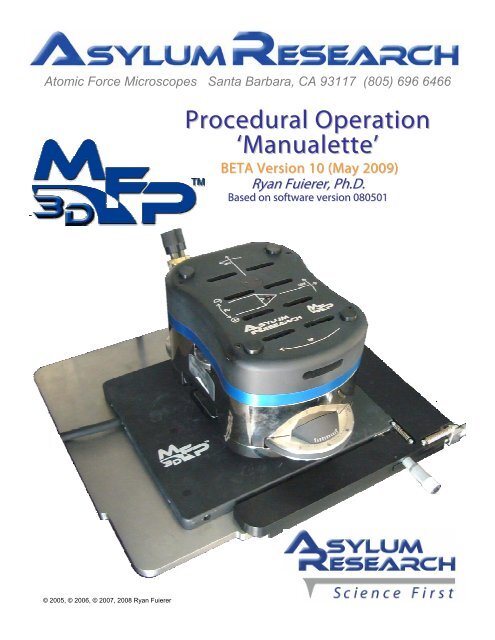
Atomic Force Microscopes Santa Barbara, CA 93117 (805) 696 6466<br />
Procedural Operation<br />
‘Manualette’<br />
BETA Version 10 (May 2009)<br />
Ryan Fuierer, Ph.D.<br />
Based on software version 080501<br />
© 2005, © 2006, © 2007, 2008 Ryan Fuierer
MFP-3D Procedural Operation ‘Manualette’ Version 10 (v080501; Igor 6.04A)<br />
ii<br />
1. Introduction to the MFP-3D<br />
3D<br />
2. Opening the MFP-3D<br />
3D software<br />
3. Loading the Probe<br />
4. Aligning the Laser<br />
5. Thermal Tuning<br />
6. AC mode Operation: 6.1 in Air; 6.2 In Fluid<br />
7. Managing Image Windows<br />
8. Contact Mode Operation<br />
9. Spring Constant Determination<br />
10. Basic MicroAngelo use<br />
11. Basic Force Spectroscopy<br />
12. Introductory Data Analysis<br />
13. ARgyle 3D Image Rendering<br />
14. Misc. Procedures<br />
16. Noise Measurements<br />
17. RF Quick Reference
Ryan’s MFP-3D Procedural Operation ‘Manualette’ Version 10 (v080501; Igor 6.04A);<br />
ix<br />
The purpose of this ‘Manualette’ is to offer new and infrequent MDP-3Dusers some supplemental<br />
documentation on how to procedurally operate an Asylum Research MFP-3D AFM. It’s like a manual, but<br />
more brief and to the point regarding basic ‘how-to’ operational procedures. It started off as a small document,<br />
and was termed the manualette. Its inception was to alleviate time spent training lab members during the<br />
author’s post doc days, but has evolved to this document in efforts to reduce the operational learning curve to<br />
achieve your efficiency.<br />
Also note that this instrument’s standard software is highly versatile, and describing even the most<br />
straightforward techniques in our user base is quite an undertaking. Adding the openness of the software, MFP-<br />
3D accessories (heaters, ORCA, VFM, etc.) and signal routing with the crosspoint switch, makes the instrument<br />
mind-numbingly versatile, and there may be a good chance it’s not described.<br />
It is assumed that the official MFP-3D manual has been perused. The MFP-3D is an expensive, high<br />
precision instrument, and should be treated with great care and common sense. AFM does take patience since<br />
it is an instrument that must be tuned and have proper sample preparation to be successful.<br />
A great effort has been made to ensure this manualette is as accurate as possible, but its accuracy and<br />
completeness cannot be guaranteed. Despite the best efforts by the author, this manualette may contain<br />
mistakes and the reader should use this only as a general guide for operation of the MFP-3D atomic force<br />
microscope, and is not the ultimate source of information about this instrument. The author assumes no<br />
responsibility for any damage whatsoever by persons or property that may result from readers undertaking<br />
operation of the MFP-3D.<br />
This Manualette:<br />
• Is broken down into sections that are in a (seemingly) logical progression for obtaining AFM images or simple<br />
force spectroscopy experiments, and the subsequent (basic) data analysis.<br />
• Only discusses operation of the MFP-3D itself, and does not include any optical microscopy techniques (if<br />
your MFP-3D happens to be sitting on an inverted optical microscope), or operation of electrical techniques or<br />
accessory modules at this time.<br />
• Is in continual development, so more insightful, updated versions will occur in the future. Version 10 by far is<br />
the largest and most comprehensive to date.<br />
If you are not familiar with Igor Pro, you should read through the ‘Getting <strong>St</strong>arted’ manual that comes with the<br />
software documentation. It’s a worthwhile use of a couple hours.<br />
The author also suggests when updating new software from Asylum, to read the ‘what’s new read<br />
me’ files; they are often very descriptive.<br />
The ‘MFP3D Help Files’ under the Igor Help menu are also very useful, especially for image<br />
analysis and display. The programmers write these for a reason, and are generally very<br />
insightful, yet sometimes not procedural- hence, the manualette.<br />
Some features of this manualette-<br />
-Any word in gray bold text in single quotes means it’s an execution button in the software; example ‘Simple<br />
Engage’, represents this button:<br />
The ▪ bullet points denote a new concept or comment.<br />
?
Ryan’s MFP-3D Procedural Operation ‘Manualette’ Version 10 (v080501; Igor 6.04A);<br />
x<br />
Checkmarks denote part of a procedure, typically these are set up in a series of instructions and are included<br />
to help guide the eye through specific operations.<br />
Blue text (accompanied by one of the little note icons in the margin) represents a Note or<br />
empirical trick- something the author has picked up along the way, and is included in<br />
efforts to reduce time to arrive at epiphany.<br />
These icons represent caution should be used to proceed.<br />
Advanced questions should be directed towards the excellent, friendly staff at Asylum Research via<br />
emails to: support@asylumresearch.com, which are forwarded to all of our technical people. It is<br />
company policy to respond to email within a 24 hour period.<br />
Have fun imaging! - Ryan
Ryan’s MFP-3D Procedural Operation ‘Manualette’ Version 10 (v080501; Igor 6.04A);<br />
xi<br />
The author would like to acknowledge all the inmates at Asylum Research who have<br />
answered the many questions between my post doctoral days when first starting to<br />
use the MFP-3D until now, allowing this document to be prepared and presented as<br />
accurately as possible. More than ¾’s of the company has been involved in the technology transfer.<br />
• The author is especially grateful to Scott MacLaren (UIUC material research lab) for taking the time to<br />
carefully edit this document, convey some interesting software techniques, provide valuable discussion<br />
and detailed descriptions of document typos and format issues that became transparent over time from<br />
excessive staring. Scott Rocks!<br />
http://cmm.mrl.uiuc.edu/staff/ScottM.htm<br />
• The author would also like to thank <strong>St</strong>efan Vinzelberg (Applications scientist with Atomic Force in<br />
Manheim Germany) for his particles program, and pedagogy.<br />
The author would not like to thank Keith Jones (AR applications scientist).
Ryan’s MFP-3D Procedural Operation ‘Manualette’ Version 10 (v080501; Igor 6.04A); 1.1<br />
to the MFP-3D components:<br />
Head: this is what contains the optical detection system and controls the Z piezo actuation of<br />
the cantilever; it contains thumbwheel adjustments to position the laser and zero the deflection on the position<br />
sensitive diode/ detector (PSD); the top view optics position knobs and focus wheel to view the tip from above;<br />
has three independent legs that adjust height of head relative to sample. Use two hands to lift the head due to<br />
its weight.<br />
Figure 1.1: MFP-3D head; ‘Extended’ Z range head shown<br />
Probe: the probe is what the entire tip/cantilever/substrate chip is called. The MFP-3D cantilever holder<br />
accommodates all major brands of commercially available probes.<br />
Probe<br />
substrate<br />
Tip<br />
Cantilever<br />
Figure 1.2: Anatomy of the Probe: entire assembly is called the probe (red ellipse).
Ryan’s MFP-3D Procedural Operation ‘Manualette’ Version 10 (v080501; Igor 6.04A); 1.2<br />
A<br />
B<br />
Figure 1.3: MFP-3D cantilever holder: A) older Kel-F design; B) newer<br />
PEEK filled glass design.<br />
Cantilever holder: this is what secures the probe chip; where the ‘shake’ piezo is housed. It snaps into the head<br />
via kinematic machine mount. The cantilever is held at an 11° angle to the surface.<br />
It consists of:<br />
-a Kel-F body (Figure 1.3A) or PEEK filled glass (tan colored; (Figure 1.3A)).<br />
-stainless steel tongue clamp to secure probe<br />
-quartz window for optical path where the laser bounces off the back of the cantilever & top view optics; pogo<br />
pins for shake piezo, applying bias to tip.<br />
Figure 1.4: MFP-3D base with XY scanner: A) <strong>St</strong>and alone base; B) Bio baseplate (not attached to<br />
inverted stage and without top view optics pillar).<br />
X,Y Scanner and Base: The flexure based 90 μm x 90 μm X,Y scanner sites on the base. The smaller holes in the<br />
scanner are where the 3 legs of the head go through to sit on the baseplate stage. The scanner can be manually<br />
moved relative to tip using the coarse translation micrometers (front right corner). Figure 1.4 shows a stand<br />
alone base, however, the MFP-3D can also be mounted onto a baseplate that sits on an inverted optical<br />
microscope frame.
Ryan’s MFP-3D Procedural Operation ‘Manualette’ Version 10 (v080501; Igor 6.04A); 1.3<br />
A<br />
B<br />
Figure 1.5: MFP-3D all digital controller: A) Original design; B) new ARC2 design<br />
(spring 2008).<br />
Controller: The digital controller contains a DSP and FPGA, and software controlled analogue ‘cross point<br />
switch’ for rerouting internal and external signals for custom experiments. The front panel of the controller is<br />
where: the power switch is; the key to turn the ‘laser’ on/ off; the ‘Hamster’ wheel is located to fine tune<br />
imaging/ control parameters; BNCs for advanced input/output signal access. The controller communicates with<br />
the PC via USB interface. There’s a lot more going on under the hood…
Ryan’s MFP-3D Procedural Operation ‘Manualette’ Version 10 (v080501; Igor 6.04A); 2.1<br />
Open the MFP-3D software; the launch icon is on desktop.<br />
▪ The software is fully loaded when Igor says it’s ready (lower left hand side of window). When Igor is busy, it<br />
doesn’t want to be interrupted and will ignore any subsequent requests until finished; while this is occurring,<br />
typically the ‘Abort’ button in the lower left of the MFP-3D software tray is present. The ‘Abort’ button can be<br />
clicked to abort a software request or calculation. This isn’t recommended during software boot up because it<br />
won’t load fully.<br />
▪ When the software is loaded, Igor will say ‘Ready’ instead of the ‘Abort’ button, and will look something like<br />
Figure 2.1, lower left.<br />
software version<br />
Open default image<br />
channels<br />
‘Setvar’ parameter windows<br />
S&D Meter<br />
‘Master’<br />
Panel<br />
Smart<br />
<strong>St</strong>art<br />
Master<br />
Channel<br />
Panel<br />
Command line<br />
Figure 2.1: Default MFP-3D software upon launching.<br />
History Window<br />
XOP version
Ryan’s MFP-3D Procedural Operation ‘Manualette’ Version 10 (v080501; Igor 6.04A); 2.2<br />
Other features of the MFP-3D software tray (see Figure 2.2)<br />
Igor Pro status- if Igor is ready to accept a<br />
software request from you, it will say ‘Ready’. If<br />
not, it’s thinking and the Abort Button is present<br />
with a rotating quartered circle.<br />
The Rescan button- push this when Igor gets<br />
confused- usually necessary if Igor freezes up, or<br />
when adding new components to the system<br />
(heaters, different cantilever holders which have<br />
identity resistors in them.<br />
Smart <strong>St</strong>art- this shows you what MFP-3D<br />
components are communicating with each other.<br />
Further more, individual information on each<br />
component can be accessed by expanding using<br />
the triangular button () to the right of each<br />
component icon<br />
1 2 3 4 5 6 <br />
Figure 2.2; The MFP-3D software tray:<br />
MFP-3D status- this will tell you if the instrument is ready, or if the controller or other hardware isn’t found,<br />
etc. If new hardware is plugged in, it will notify you as it reads the calibration files off the new hardware.<br />
Quick link to AR online support (AR engineers can control your MFP-3D over the web during online help<br />
sessions).<br />
CCD top view camera icon- click this to get camera screen to come up.<br />
7 MFP-3D XOP version<br />
NOTE: For more about having multiple version of the MFP-3D software on your machine, see Section 14.16, or<br />
go to http://www.asylumresearch.com/Support/FAQ3D.shtml#IgorCopy.<br />
Mode Master Panel-<br />
In versions after March of 2008, an additional panel during the MFP-3D software boot will appear with the<br />
Mode Master Panel (Figure 2.3)- this was created in efforts to make the software more user friendly for new our<br />
infrequent users. What’s great about the Mode Master is that it can be set up such that clicking on a technique<br />
reconfigures the panels to be parameter ready for the technique at hand. For example, clicking on the electrical<br />
then SKFM brings up the electrical tune panel and the NAP panel, along with the NAP channel panel.<br />
To use the Mode Master, just click on a function button- for example, say you want to imaging in Contact<br />
mode:<br />
Click ‘Topography’ button; this will bring up a panel with all the different topography acquisition modes.<br />
Click the ‘Contact Mode’ button; this will bring up all the parameters used for contact mode imaging (See<br />
Chapter 8).<br />
Mode master has undergone some improvements from earlier versions and it apparently more user friendly<br />
and remember spring constants and other calibration items that used to be reset when changing modes.
Ryan’s MFP-3D Procedural Operation ‘Manualette’ Version 10 (v080501; Igor 6.04A); 2.3<br />
Figure 2.3: MFP-3D Mode Master Panel simplifies parameter selection<br />
with preset or user defined parameters established prior. B) clicking on<br />
topography brings up a sub-panel allowing the user to select between<br />
different topography imaging modes. Each of these modes will<br />
reconfigure software parameters to best suit the experiment.
Ryan’s MFP-3D Procedural Operation ‘Manualette’ Version 10 (v0800501; Igor 6.03A); ©2008 3.1<br />
This section describes how to properly load a probe into the cantilever holder,<br />
and place the head onto the stage.<br />
Section Topic<br />
page<br />
3.1 Loading the Probe 3.1<br />
3.2 Placing head on scanner stage 3.3<br />
3.1: Loading the Probe:<br />
The MFP-3D cantilever holder accepts most brands of commercially available probes. The quartz window is<br />
resilient from tweezer scratches. It can be cleaned a variety of ways- see official MFP-3D manual. It can be found<br />
on the AR forum found under manuals and documentation:<br />
http://asylumforum.com/forum/showthread.php?t=372<br />
Load tip holder into loading pedestal apparatus (Figure 3.1A), which offers stability when loading tips. The<br />
cantilever holder has a kinematically machined ball bearing port that snaps into place using the lever on the<br />
apparatus and head port. If working in buffers or solvents that must be rinsed post experiment, the cantilever<br />
holder pedestal apparatus works great for rinsing the tip holder after imaging (i.e, so you don’t drop it into the<br />
rinsing collection container).<br />
Loosen tongue clamp screw with provide Phillips head screwdriver (it’s a right hand thread).<br />
A B C<br />
Optical window<br />
Probe<br />
D<br />
Image courtesy of Jeff Honeyman<br />
E<br />
Good Probe Position<br />
Bad Probe Position<br />
Figure 3.1: Proper probe loading: A) loading the cantilever holder into the cantilever holder stand. B)<br />
use tweezers to position cantilever in middle of polished quartz window. C) proper position of probe in<br />
quartz window. D) Proper position of probe in pocket; if too far back, probe slides on back ledge of<br />
pocket compromising deflection signal; E) Screw tongue clamp- no more than finger tight - with a<br />
Phillips (00x40) screwdriver.
Ryan’s MFP-3D Procedural Operation ‘Manualette’ Version 10 (v0800501; Igor 6.03A); ©2008 3.2<br />
Slide probe chip under tongue clamp. Position cantilevers so that they are centered (more or less) in the clear<br />
trapezoidal shaped quartz optical window (Figure 3.1B & C). The cantilever holder was designed to be resilient<br />
to scratching from tweezers, so don’t be paranoid. For best results, DO NOT push probe chip substrate all the<br />
way back in the pocket: it can cause the probe chip to lift off the floor of pocket, compromising the deflection<br />
signal (i.e., no signal). Figure 3.1D illustrates this schematically.<br />
Tighten the screw in the center of the stainless steel tongue assembly (NO MORE THAN finger tight!). This<br />
generally allows for suitable chip coupling to the tip holder. (Figure 3.1E)<br />
NOTE: DO NOT OVER TIGHTEN TONGUE CLAMP on cantilever holder- this can strip screw<br />
threads; or result in excessively bending the tongue, and cause some issues with obtaining<br />
suitable deflections between different Probe manufacturers or cantilever lines. If this does<br />
happen, the clamp can easily (yet gently & patiently) be bent back into place. (See Misc.<br />
Operations Section 14 to review this procedure.)<br />
Accommodating Thicker Probe Substrates:<br />
Often when switching between silicon probes to SiNx<br />
probes, the thickness difference offers some difficulty in<br />
gently sliding the probe chip under the tongue clamp near<br />
the hinge (not at end of tongue!- see Figure 3.2 )- this is because<br />
there is a thickness difference between the two types, and from<br />
manufacturer to manufacturer. If some resistance is felt, and the<br />
probe just won’t gently slide under the tongue clamp into the<br />
pocket, here’s what to do:<br />
GENTLY take tweezers or flat head screwdriver to GENTLY pry up<br />
on tongue near base (see tweezer placement in Figure 3.2.). Did I<br />
state GENTLY? The author’s experience is that it doesn’t even have to<br />
feel like the probe tongue clamp was moved at all. This is usually enough to allow new probe to slide under<br />
without resistance.<br />
As of spring 2009, there is no fix for the thinner Veeco probe substrates.<br />
Figure 3.2: GENTLY lifting tongue<br />
clamp to accommodate thicker probe<br />
chips.<br />
Install cantilever holder into MFP-3D head:<br />
Put cantilever holder into the MFP-3D head- the author finds it easiest to put the ball bearing on release<br />
lever side (red arrow, Figure 3.3 below) of the kinematic system first; then ease the holder in from the back.<br />
Make sure the cantilever holder is parallel to the top of the head; other wise it is not properly seated (see note<br />
below).<br />
Use extreme care when putting cantilever holder into the MFP-3D head. The ‘pogo’ pins used to<br />
get signals from the cantilever holder can be easily bent with excessive force (Figure 3.4 below).
Ryan’s MFP-3D Procedural Operation ‘Manualette’ Version 10 (v0800501; Igor 6.03A); ©2008 3.3<br />
Figure 3.4: Location of ‘pogo’ pins in<br />
head (red circles)<br />
Figure 3.3: Cantilever holder properly installed in MFP-3D head. The red arrow<br />
shows location of the button for the cantilever holder release lever.<br />
3.2: Placing Head on Scanner <strong>St</strong>age:<br />
A<br />
Once a probe is properly installed in the cantilever<br />
holder, the superluminescent diode (SLD) can be aligned<br />
on the stand next to the base (with kinematic machined<br />
leg divots) IF using the IR card,<br />
-ORover<br />
the sample IF using the CCD camera. To do the<br />
latter, the head must first be placed on the stage.<br />
A detailed description of aligning the SLD is described in<br />
Chapter 4.1A&B, for IR card and CCD camera,<br />
respectively.<br />
B<br />
Lift the head with two hands and place the back two<br />
legs in the kinematically machined divots on the MFP-3D<br />
baseplate (Figure 3.5A).<br />
Move hands so thumbs are under the front of head,<br />
and slowly lower head towards stage using back legs as<br />
pivot point; continually monitoring the tip – sample<br />
separation (Figure 3.5B) with your visual spectroscopy. If<br />
it looks as though the tip will crash, lift/ pivot head back<br />
Figure 3.5: Installing the head onto base plate over<br />
sample: A) use two hands to lift head, set back two legs<br />
onto base plate first; B) gently lower front leg down,<br />
constantly monitoring tip sample distance to avoid tip<br />
crash.
Ryan’s MFP-3D Procedural Operation ‘Manualette’ Version 10 (v0800501; Igor 6.03A); ©2008 3.4<br />
up and adjust legs down to increase tip-sample separation, and repeat process.<br />
▪ The top view CCD camera can also be monitored.<br />
▪ (if not choosing the SLD alignment via IR card route,) Once all three legs of the head are on the stage,<br />
align the SLD on back of cantilever, as described in Section 4.1B.<br />
When working in a fluid droplet or fluid dish, it’s more difficult to monitor this tip sample separationa<br />
safe approach is to have a great deal of distance (>200μm) between the two, and then use the CCD<br />
camera to monitor this approach. Figure 3.6 shows the meniscus created between tip and sample<br />
when plunging cantilever holder into fluid. See Section 6.2. for more on fluid imaging (AC<br />
mode). MAKE SURE NOT TO SUBMERGE CANTILEVER HOLDER IN FLUID!- See Figure 6.2.2B.<br />
A B C<br />
Fluid droplet<br />
meniscus<br />
Figure 3.6: Installing head over sample with fluid droplet: A) tip approaching droplet; B) Surface tension/ capillary<br />
forces connect fluid meniscus to cantilever holder; C) head is lowered until front leg is on stage. Be sure fluid meniscus<br />
stays around tip and sample to avoid scanner damage.
Ryan’s MFP-3D Procedural Operation ‘Manualette’ Version 10 (v080501; Igor 6.04A); 4.1<br />
This section describes multiple ways to align the ‘laser’ on the<br />
cantilever, and zero the Photodector prior to imaging. The<br />
‘laser’ is actually a super luminescent diode (SLD, emits at<br />
~860 nm), and will be referred to the SLD.<br />
Section Topic page<br />
4.1 SLD alignment 4.1<br />
4.1A via IR card 4.2<br />
4.1B via CCD camera 4.3<br />
4.2 Zeroing Photodector 4.6<br />
4.3 Troubleshooting 4.6<br />
4.1: SLD Alignment:<br />
There are two ways to initially (coarse) align the SLD on the cantilever: 1) use an IR card (described in Section<br />
4.1A); 2) use top view optics CCD camera*(described in Section 4.1B). Fine alignment involves using the LDX &<br />
LDY alignment thumbwheels to maximize the sum voltage in the S&D meter, and subsequently ‘zeroing’ the<br />
SLD spot on the photodiode detector (PD)- see Section 4.3.<br />
* for use top down view optics CCD camera only; there are MFP-3D heads out there with no top view optics<br />
Deflection (PD)<br />
adjustment<br />
Camera focus<br />
C<br />
B<br />
D<br />
E<br />
X-, Y- CCD<br />
camera<br />
translation for<br />
top view optics<br />
F<br />
A<br />
Engagement<br />
thumbwheel<br />
SLD<br />
adjustments<br />
Figure 4.1: AFM head with the various alignment thumbwheels labeled<br />
▪ The top of the MFP-3D head is conveniently labeled (Figure 4.1), including the orientation of the probe<br />
(with an LED being in the center of the triangular cantilever representation). The thumbwheel on the right<br />
moves the SLD along the length of the cantilever (LDX), while the one on the back of the head moves it across<br />
the cantilever (LDY). The head has arrows indicating which way the SLD will go as they are moved CCW. The<br />
left side of the head has a thumbwheel that adjusts the vertical deflection on the position sensitive<br />
photodiode (PD).
Ryan’s MFP-3D Procedural Operation ‘Manualette’ Version 10 (v080501; Igor 6.04A); 4.2<br />
Turn on the SLD by turning the key on the front of the controller 90º<br />
clockwise (CW; Figure 4.2). Some activity in the Sum Voltage value on<br />
the S&D meter will also occur.<br />
4.1A: SLD Alignment via IR card:<br />
(for use with heads without camera, or for the MFP purists):<br />
This is done on a stand that is kinematically machined for the legs, or a<br />
table top- i.e., not on top of the sample.<br />
Place the IR card under the tip holder. Figure 4.3 (below) attempts to<br />
depict the procession needed to align the SLD. If the SLD spot isn’t<br />
being blocked by anything, you can see it on the IR card. If you can’t<br />
see it, move the SLD spot (using the LDX thumbwheel on the right side<br />
of the head, ‘A’ in Figure 4.1) along the length of the cantilever until you do- Figure 4.4A shows the visible SLD<br />
spot on the IR card. If no spot is seen on the IR card, perhaps it may need charging for a few seconds under a<br />
fluorescent light.<br />
CAUTION: When adjusting any of the alignment thumbwheels, if<br />
you feel resistance turning them, DON’T FORCE IT- It’s probably<br />
at the end of its travel. If you over torque, it becomes very difficult<br />
to reverse its direction, OR the belt that is attached to the knobs<br />
to turn the pivot points on the optical assembly can get irreversibly<br />
screwed up, and it will have to be repaired at the factory. Use gentility<br />
when adjusting the LDX, LDY & PD knobs.<br />
Then follow this procedure:<br />
Move the SLD spot back onto the support chip via LDX thumbwheel (no<br />
spot visible- depicted in Figure 4.4B; or Action 1-Figure 4.3).<br />
Figure 4.2: laser power on face<br />
of controller<br />
Move SLD spot until you see it on the card (spot visible- like Figure 4.4A; or Action 2-Figure 4.3);<br />
▪If the SLD spot is outside the transparent quartz window, it won’t be visible on the IR card. This is indicated by<br />
the hatched area in Figure 4.3.<br />
Probe<br />
chip<br />
A<br />
B<br />
Figure 4.3: laser alignment pattern<br />
Figure 4.4: A) laser spot visible on IR card; B) laser spot not visible on IR<br />
card because it’s being blocked by probe substrate
Ryan’s MFP-3D Procedural Operation ‘Manualette’ Version 10 (v080501; Igor 6.04A); 4.3<br />
Now use the LDY thumbwheel on the back side of the head (‘B’ in Figure 4.1) to adjust the beam<br />
perpendicular to the length of the cantilever (Sweep 3, Figure 4.3) WHILE MONITORING THE S&D METER.<br />
There will be some activity (new value) in the ‘Sum’ Voltage on the S&D meter when the SLD crosses the<br />
cantilever.<br />
Maximize/ optimize the ‘Sum’ voltage signal using both LDX & LDY thumbwheels (Sweeps 4, Figure 4.3)<br />
Move the LDX thumbwheel out (CCW) along the cantilever until the ‘Sum’ voltage in the S&D meter<br />
decreases to a small value again- this means the SLD spot is off the end of the cantilever.<br />
Move the LDX thumbwheel (CW) so the ‘Sum’ voltage reappears again; stop at a maximum value. The goal<br />
is to place the SLD spot towards the end of the cantilever to maximize the optical lever sensitivity.<br />
Move the LDY thumbwheel slightly to maximize the ‘Sum’ voltage in the S&D meter.<br />
NOTE: for the most sensitivity in cantilever deflection, the SLD spot needs to be towards the end of<br />
the cantilever, as opposed to the base where it meets the probe chip. If the SLD spot is near the<br />
probe chip, the range of deflection won’t be as large, regardless of how large the Sum signal may be.<br />
See Figure 4.9 for visual example.<br />
▪At this point, SLD should be properly aligned.<br />
4.1B: SLD Alignment via top view CCD camera:<br />
This method is a great way to actually see where the SLD spot is relative to the cantilever. It is also (generally)<br />
necessary when working in fluid, especially with functionalized probes.<br />
▪ To actually see something with the CCD camera, the MFP-3D head needs to be over the sample. It’s a focus<br />
distance thing.<br />
BE SURE THERE IS ENOUGH ROOM BETWEEN SAMPLE AND TIP SUCH THAT IT DOESN’T CRASH AS THE<br />
HEAD IS PLACED OVER THE SAMPLE! If this does happen, the head won’t be damaged (it’s very robust), but<br />
the tip and sample will certainly be compromised.<br />
In the MFP-3D software, look for the CCD icon at the lower left tray of the MFP-3D software<br />
screen. If the fiber light is off, a black screen will come up in the software which is the video<br />
image.<br />
ccd icon<br />
Turn on the power to the fiber light; using the variable potentiometer knob, increase illumination until you<br />
can see the tip in the CCD window.<br />
FOR DUAL VIEW SYSTEMS ONLY: If the tip is<br />
not visible in the CCD image using a MFP-<br />
3D Dual View <strong>St</strong>and Alone system,<br />
perhaps the top view optics and illumination shutter<br />
are set for bottom view- go to the <strong>St</strong>and alone base<br />
and make sure both shutters are pulled out (See<br />
Figure 4.5). The author commonly makes this<br />
mistake.<br />
Figure 4.5: Top view optics on Dual View <strong>St</strong>and Alone base<br />
require illumination and camera shutters to be pulled out.
Ryan’s MFP-3D Procedural Operation ‘Manualette’ Version 10 (v080501; Igor 6.04A); 4.4<br />
The default CCD image in the software is for a composite (RCA) video cable jack (yellow plug;<br />
below left)- If you are using a MFP-3D Bio, the CCD uses a S-video (4 pin jack; below right).<br />
Click the ‘Source’ button at the top of the CCD software window (red circle), which will change from<br />
Composite to S-Video. These jacks can be seen in the MFP3D base, and at the PC.<br />
Figure 4.6: Click the ‘Source’ button to switch between composite/<br />
RCA video (stand alone bases), or S-Video (MFP-3D- Bio).<br />
Composite<br />
S video<br />
▪ To adjust the CCD image focus, use the thumbwheel in the optics housing on the back of the head (‘D’ in<br />
Figure 4.1): CCW move the focus towards the sample.<br />
▪ To adjust the location of the viewing field of the CCD camera, use the X and Y translation knobs on the back<br />
of the optics housing (‘E’ in Figure 4.1).<br />
▪ Aligning the SLD using the CCD camera uses an approach similar as with IR card, but you can see the SLD<br />
spot with relation to the cantilever.<br />
Using the LDX thumbwheel, move the SLD spot onto the back of the probe substrate- due to some<br />
diffraction thing I probably cannot explain (it is important that you see some elongation diffraction to the<br />
spot- this is the correct spot to use- see Figure 4.7A); If a spot without this elongation is seen (like the one in<br />
Figure 4.7B), it is the wrong spot and will give no ‘Sum’ voltage in the S&D meter even though there appears<br />
to be a spot on the end of the cantilever. A second example can be seen in Figure 4.10 at the end of this<br />
section.<br />
A<br />
B<br />
Figure 4.7: A) proper SLD spot with elongated appearance; B) SLD without elongation will<br />
give no appreciable Sum voltage. NOTE: spot on probe chip for demonstration only.<br />
• Certain focal planes can also give the appearance that the spot is not on the cantilever in the CCD image,<br />
when in fact it is because the Sum voltage in the S&D meter.
Ryan’s MFP-3D Procedural Operation ‘Manualette’ Version 10 (v080501; Igor 6.04A); 4.5<br />
If there is any question if the spot is aligned on the cantilever OR the probe substrate, there is a very<br />
easy way to tell- do a thermal tune! See Thermal Tuning (Section 5) for explicit instructions. If the SLD<br />
spot is on the Probe chip, there won’t be any resonant peak (with significant amplitude or Q) in the<br />
power spectrum.<br />
▪A second way to align the SLP spot using the CCD camera is to find the spot on the substrate- Scott<br />
Maclaren (MRL-UIUC) taught me this protocol.<br />
Turn the illumination down very low on the fiber light.<br />
Locate the SLD spot on the substrate- the author usually locates a diffracted spot that is along the same<br />
vector as the length of the cantilever. In Figure 4.8A, the actual SLD spot isn’t vary apparent (red circle), but<br />
the diffracted spot is in line with the cantilever vector. Please make exception to the author’s careless probe orientation<br />
in this example.<br />
Move LDX thumbwheel towards probe chip- the SLD spot is now reflecting off the cantilever (Figure 4.8B);<br />
there is a great deal of refracted light, presumably due to the low fiber light illumination level. Slight<br />
adjustment in LDY may also be needed to maximize ‘Sum’ voltage in S&D meter.<br />
▪ When increasing the fiber light illumination, the spot is more apparent, and the amount of refracted light in<br />
the CCD image decreases (Figure 4.8C).<br />
▪ Alternatively, you can sweep the SLD spot until it crosses the cantilever; then maximize ‘Sum’ voltage.<br />
A Diffracted B C<br />
spot<br />
Figure 4.8: Aligning SLD starting with spot on substrate via CCD camera: A) using low fiber light illumination,<br />
locate SLD spot on substrate; B) move LDX and LDY thumbwheels until SLD spot is on end of cantilever with<br />
maximized ‘Sum’ voltage: C) increased fiber light illumination reduces refracted light seen in CCD image.<br />
• Regardless of how the SLD spot is aligned on the back of the cantilever, what is desired is to have the spot<br />
towards the end of the cantilever to maximize the optical lever sensitivity (Figure 4.9A). When the spot is at<br />
the base of the cantilever (Figure 4.9B), the optical lever sensitivity decreases (i.e., InvOLS value increases- see<br />
Section 9.1, page 9.5).<br />
A<br />
B<br />
Figure 4.9: align SLD spot towards end of cantilever to maximize optical lever sensitivity;<br />
B) shows spot at base of cantilever, which yield low optical lever sensitivity.
Ryan’s MFP-3D Procedural Operation ‘Manualette’ Version 10 (v080501; Igor 6.04A); 4.6<br />
4.2: Zero Photodector (PD): Now look at the ‘Deflection’ voltage signal in the S&D meter-<br />
This meter window is set up rather conveniently: If you have red in the deflection meter, you need to go<br />
negative to adjust to ~0 V (towards blue). The top of the head is labeled to tell you what way to go (positive or<br />
negative; see Figure 4.1; label ‘C’).<br />
Use the PD thumbwheel (‘C’ in Figure 4.1) to do this: if the deflection value in the S&D meter is negative<br />
(blue), move thumbwheel CCW to get to ~0V; if the deflection signal is positive, move the PD thumbwheel CW<br />
to ~0V.<br />
If you are working in fluid, there will be some thermal gradient causing the deflection to drift- use<br />
the PD thumbwheel to adjust this back to ~0V before beginning your AFM application. Typically,<br />
the first 20 minutes in fluid show the most pronounced amount of Deflection drift due to system<br />
equilibration.<br />
4.3: TROUBLESHOOTING:<br />
No significant Deflection voltage, or very low Sum voltages: typically either the cantilever isn’t seated in<br />
the pocket well- perhaps some debris is acting as a fulcrum moving the orientation of the lever our of the<br />
proper plane;<br />
• Sometimes the probe is bad, or worse, there is no cantilever on the probe (verify in CCD camera).<br />
‘Digital Wrapping’ in the PD value: Say you are trying to zero the PD deflection from some ‘railed’ value in<br />
the deflection voltage in the S&D meter. No matter how much you turn the thumbwheel the way it’s<br />
supposed to go, the deflection doesn’t budge from that railed value (even if you go to the end of the travel<br />
and the thumbwheel starts to bind- AGAIN, DON’T FORCE IT!). What is likely occurring is something called<br />
‘digital wrapping’ of that deflection value.<br />
So here’s what to do-<br />
Reverse the thumbwheel direction such that the turn is towards the same sign as your displayed deflection<br />
in the S&D meter (i.e, lets say the deflection value is railed positive- turn PD thumbwheel towards the positive,<br />
instead of toward negative)- what you’ll find is at some point, the deflection sudden becomes railed negative;<br />
but the way it was displayed, it became wrapped to the positive. Then just keep thumbing the PD that way<br />
and it’ll easily be zeroed. This is hard to explain in text, but easy to fix practically.<br />
Reducing abuse on head cable:<br />
Be careful not to torque/twist the cable to head: always follow the<br />
same rotation path as you took head off with. The head cable should<br />
only experience 180º worth of rotation in its regular on stage, off stage<br />
cycling.<br />
Continual twisting of the head can:<br />
1) Break down the head cable over time (see Figure 4.10).<br />
2) Torque the cable such that mechanical noise is more easily coupled<br />
into the head b/c of the torque. This can also add thermal drift into<br />
your system.<br />
Figure 4.10: Excessive twisting of cable<br />
causes damage.
Ryan’s MFP-3D Procedural Operation ‘Manualette’ Version 10 (v080501; Igor 6.04A); 4.7<br />
A<br />
B<br />
Figure 4.11: Another example of the correct SLD spot in A), and the incorrect SLD spot in B). The difference in<br />
A) & B) is that the LDY thumbwheel was moved CW. In reality, the correct SLD spot in B) is just off the CCD<br />
camera field of view (it’d be below the image). NOTE: SLD spot displayed over probe chip to show entirety of<br />
diffraction pattern<br />
It is common that the system will experience some drift within the first 30 minutes or so- AR<br />
engineers think this may be mostly do to with the head "settling" into position in its kinematic<br />
mount. Internally acquired Drift vs. Temp graphs suggest the data from this period isn't very<br />
correlated with temperature, but more related to time, suggesting this settling.
Ryan’s MFP-3D Procedural Operation ‘Manualette’ Version 10 (v080501; Igor 6.04A); 5.1<br />
A Thermal tune is performed to determine the natural resonant frequency of the cantilever by monitoring the<br />
amplitude over a user defined frequency range. The MFP-3D uses the PD A/D converter to measure this,<br />
which can acquire frequencies up to 2.5 MHz.<br />
Thermal Tunes are mostly used for a few specific tasks:<br />
To determine the frequency of a cantilever for drive frequency selection for AC mode in air or fluid; OR<br />
higher resonance eigenmodes for DualAC imaging techniques.<br />
Is the second step in determining the spring constant (see Section 9 for the complete cantilever spring<br />
constant, k, determination protocol).<br />
Determining resonant frequency changes if the tip has picked up material (or has become broken).<br />
The Thermal tab is located in the Master Panel, seen in Figure 5.1.<br />
Figure 5.2: Power spectrum of typical AC 160 Si cantilever in air.<br />
Red arrow points to fundamental resonant frequency of cantilever.<br />
Figure 5.1: The Thermal tab.<br />
Figure 5.3: Pre thermal tune dialogue if PSD<br />
isn’t zeroed.<br />
Assuming a probe is properly loaded, SLD aligned and the PD zeroed, follow the below procedure to acquire a<br />
thermal tune of the cantilever-
Ryan’s MFP-3D Procedural Operation ‘Manualette’ Version 10 (v080501; Igor 6.04A); 5.2<br />
Click the ‘Do Thermal’ button; a power spectrum plot similar to the one in Figure 5.2 will appear,<br />
continuously averaging spectrums in real time. In this example, an Olympus AC 160 Si cantilever in air was<br />
used. The higher Q of the cantilever causes the sharp peak in air.<br />
▪ If the deflection isn’t zeroed, a dialogue like the one in Figure 5.3, will come up- don’t be alarmed: either click<br />
‘No’ and zero the PD, or if precision isn’t your top priority, click ‘Yes’ and continue. The reason to zero them is<br />
that PDs have more linear response in their center relative to their center. The author typically zeros the PD.<br />
▪ The user can limit the number samples acquired; generally a couple dozen is sufficient for most tasks unless<br />
the S/N ratio really matters in the application. Notice the baseline is mostly noise, but the one sharp line<br />
around 300kHz is the AC160’s resonant frequency (red arrow, Figure 5.2).<br />
Click ‘<strong>St</strong>op’ button to terminate the collection of power spectrums.<br />
The resolution of the acquisition can be changed in the resolution pull down menu of the Thermal<br />
tab. Larger numbers go faster (less resolution); while smaller values acquire slower, but give less noise.<br />
The way the data is plotted (i.e., linear vs. logarithmic) can also be changed in the ‘Graph Log’ pull<br />
down menu.<br />
The bandwidth of the Thermal tune can also be selected: the default parameter is 1MHz. To change<br />
this to a larger or smaller value, click the ‘Setup’ button in the Thermal tab, and activate the ‘Show’<br />
checkbox for the Frequency Range at the bottom of the panel. Use the Freq. Range pull-down to<br />
select other Thermal Power spectrum frequency ranges (Figure 5.4A). Since the Thermal plot is default<br />
to only 1MHz, increase the scale on the thermal plot by clicking on the X axis to bring up Igor’s ‘Modify<br />
Axis’ panel and manually increase the X axis to the desired range (Figure 5.4B).<br />
A<br />
B<br />
Figure 5.4: A) Selecting different<br />
frequency ranges for the power<br />
spectrum from the Freq. Range pull<br />
down menu; B) Use Igor Modify Axis<br />
Dialogue to manually increase<br />
frequency (X axis) range to display<br />
larger ranges, in this case, 2.5MHz.
Ryan’s MFP-3D Procedural Operation ‘Manualette’ Version 10 (v080501; Igor 6.04A); 5.3<br />
Thermal tune plots can be saved by -<br />
Clicking the ‘Save’ button at the top of the thermal plot. Saves as Igor graph (.pxp)<br />
From FileSave Graph Copy… in the Igor main menu. Saves as Igor graph (.pxp)<br />
Sent to a Layout as a graphic (see Section 14.13).<br />
Zoom into the area of the peak by right mouse clicking around the peak, then right or left click to see the<br />
menu shown in Figure 5.5A.<br />
Choose ‘Expand’; the result would look something like Figure 5.5B.<br />
A<br />
B<br />
C<br />
Figure 5.5: A) Full Spectrum thermal tune; B) Zoom of resonant peak; C) The ‘fit’ peak; Red arrows show ‘fit width’ cursors<br />
on power spectrum.<br />
Next, activate the Igor cursors (⊗,), by using Ctrl + i; the cursors come up in the bottom tray of the plot.<br />
Drag one of the cursors to the peak. The example in Figure 5.5B, cursor ⊗ was placed on the resonant peak<br />
– 79.192 kHz.<br />
Type the ‘X:’ value (~79 kHz is sufficient) in the Igor cursor tray into the ‘Zoom Center’ parameter of the<br />
Thermal Tab. Note the units in the tray are in Hz, while the units in the parameter box are in kHz.<br />
Click the ‘Show Fit’ checkbox ; a blue fit line should appear on plot<br />
Click the ‘Fit Guess’ button; a blue Fit function curve appears somewhere in the vicinity of the resonant<br />
peak. If it doesn’t, confirm that the ‘Zoom center’ setvar value is in a similar range as the resonant frequency<br />
peak.<br />
Click the ‘Try Fit’ button. The blue fit function curve should be fit to the resonant peak (Figure 5.5C);<br />
meanwhile the resonant frequency value and Q parameters in the Thermal Tab are updated.<br />
• Thermal tunes work very well for determining the resonant frequencies (and ultimately drive frequencies) of<br />
cantilevers in fluid. See Section 6.2.2: ‘AC mode imaging in-fluid’ for this protocol.
Ryan’s MFP-3D Procedural Operation ‘Manualette’ Version 10 (v080501; Igor 6.04A); 5.4<br />
The thermal tune is also a very convenient way to check whether the SLD spot is on the cantilever<br />
(when aligning SLD via IR card, sometimes a nice sum is given when the spot is on the probe<br />
substrate).<br />
▪ Figure 5.6 (right) shows and example of a thermal<br />
tune when the SLD was on the back of the probe chip,<br />
yet a reasonable Sum voltage was displayed in the<br />
S&D meter.<br />
Figure 5.6: Thermal tune of SLD spot on back of probe<br />
chip - no apparent cantilever resonant frequency.<br />
▪ Figure 5.7 shows two cases in which a thermal tune can tell you what has happened if the resonant<br />
frequency changes throughout an imaging experiment. If the tip breaks (lowering mass, increasing f o ; Figure<br />
5.7A), or if there is an increase in mass on the cantilever/ tip from adhered debris (lowering f o ; Figure 5.7B).<br />
A<br />
B<br />
Figure 5.7: SEM images of compromised tips: A) broken tip, will shift f o to higher value;<br />
B) debris on tip will add mass, shift f o to lower value.
Ryan’s MFP-3D Procedural Operation ‘Manualette’ Version 10 (v080501; Igor 6.03A); ©2008 6.1<br />
AC mode imaging is one of the most commonly used imaging modes in AFM. This section will discuss how to<br />
select a cantilever drive frequency, pre-engagement imaging parameters, tip engagement, and fine tuning<br />
the imaging parameters for artifact free images. See Section 7 for changing the appearance of the image<br />
windows and saving image files. Due to the different skills that need to be used during imaging in either air or<br />
fluid, this Section has been broken down into subsections:<br />
Section Topic page<br />
6.1 AC mode imaging in AIR 6.1<br />
6.1.1 Auto Tuning 6.2<br />
6.1.2 Tip engagement 6.3<br />
6.1.2A Hard Engagement 6.4<br />
6.1.2B Gentle Engagement 6.5<br />
6.1.3 Tuning Imaging Parameters 6.6<br />
6.1.4 Monitoring Phase in AC mode 6.8<br />
6.1.4A Repulsive Mode Imaging 6.11<br />
6.1.4B Attractive Mode Imaging 6.13<br />
6.1.5 DualAC 6.17<br />
6.2 AC mode imaging IN FLUID 6.21<br />
6.2.1 Preparing for In Fluid Imaging 6.21<br />
6.2.2 Aligning the SLD 6.23<br />
6.2.3 Determining Drive Frequency In Fluid 6.23<br />
6.2.4 Tip Engagement in fluid 6.26<br />
6.2.5 Tuning Imaging Parameters 6.27<br />
6.2.6 In Fluid Precautions 6.29<br />
6.1: AC Mode Imaging in Air:<br />
The Main Tab of the Master Panel is where most of the parameters for<br />
imaging are found (Figure 6.1, right). The important parameters to tune<br />
will be Set Point voltage, Integral Gain, Drive Amplitude, Scan Rate<br />
(highlighted in red, Figure 6.1.1), and Scan Angle.<br />
From Main tab in the Master Panel, confirm that ‘AC mode’ is selected<br />
from the imaging mode pull-down menu (Figure 6.1.1). AC mode is the<br />
default imaging mode.<br />
Figure 6.1.1: Main Tab for imaging<br />
parameters<br />
▪ The ‘Hamster’ wheel (on the front of the controller, Figure 1.5) can control/ precisely fine tune parameters<br />
activated by the radio buttons. Radio buttons can be seen in Figure 6.1.1 as the circular features to the riht of<br />
certain parameter setvar windows (i.e., Scan Size, X&Y Offsets, Set Point, Gain, Drive Amplitude, Drive Freq.);<br />
specifically, the Set Point voltage radio button is activated, indicated by a green center dot.<br />
The first thing that needs to be done in AC mode imaging is to select the tip’s oscillatory drive frequency<br />
during imaging- assuming a cantilever is loaded & the SLD properly aligned, follow the below procedure to<br />
obtain AC mode images in AIR.<br />
Adjust the Deflection voltage (PD thumbwheel on the head; Figure 4.1) to ~ 0V (no color in deflection<br />
voltage S&D meter) for AC mode.
Ryan’s MFP-3D Procedural Operation ‘Manualette’ Version 10 (v080501; Igor 6.03A); ©2008 6.2<br />
6.1.1: AUTO TUNING:<br />
Open the Tune tab of the Master Panel (Figure 6.1.2).<br />
Choose a Target Amplitude of 1.0V. This means what it takes to drive<br />
the oscillate the cantilever so there is 1.0V worth of sine wave on the PSD.<br />
NOTE- For sharp tips (i.e., spikes or other expensive probes),<br />
1.0V worth of free air amplitude may be too much because the<br />
tip will be hitting the surface with more force then it might<br />
prefer- INSTEAD, choose a Target Amplitude of 300 mV or so.<br />
Proceed with the following directions, but adjust the set point<br />
(amplitude) voltage ratio accordingly.<br />
Change the ‘Target Percent’ to -5.0 %; however, depending on your<br />
application, you can assign it to any other user defined value within<br />
reason. The description below was written with -5% in mind. The minus<br />
sign indicates that the drive frequency will be on the left side of the<br />
resonant peak, which helps ensure the tip will remain in repulsive mode<br />
when engaged (see Section 6.1.4, 6.1.4A for further description of<br />
repulsive mode).<br />
The default Auto Tune ‘High’ and ‘Low’ values are ~50 kHz to 400 kHz,<br />
respectively, accommodating most (fundamental) drive frequencies for<br />
common commercially available AC mode cantilevers (in air).<br />
Click the ‘Auto Tune’ button; the frequency sweep commences.<br />
Figure 6.1.2: Tune Tab.<br />
▪ An Auto Tune plot similar to the one(s) in Figure 6.1.3 appears- initially one appears momentarily that is<br />
similar to Figure 6.1.3A; then updates to one similar to Figure 6.1.3B. The software automatically picks a Drive<br />
Frequency at a Target Percent of -5% (left side) of peak maximum at the (minimum) Drive Amplitude needed<br />
to make a 1.0 V amplitude, displayed in the S&D meter. The left side of the peak will ensure that the tip<br />
experiences net repulsive forces with the sample as it interacts with the surface.<br />
A<br />
B<br />
Figure 6.1.3: Auto tune of an Olympus AC160 Si (f~300kHz; k= 40N/m) cantilever in air: A) Early stages of<br />
Auto Tune; B) final result of Auto Tune.
Ryan’s MFP-3D Procedural Operation ‘Manualette’ Version 10 (v080501; Igor 6.03A); ©2008 6.3<br />
▪ The ‘Target Amplitude’ & ‘Target Percent’ setvars can be defined by the user, depending on the application<br />
(i.e., repulsive or attractive mode imaging, see Section 6.1.4). The Drive Frequency value will automatically be<br />
updated in the Tune and Main tabs of the Master Panel, and the Q (quality factor) of the cantilever is<br />
determined, displayed at the top of the Cantilever Tune plot in and the Tune tab.<br />
Tune plots can be saved by -<br />
Clicking the ‘Save’ button at the top of the thermal plot. Saves as Igor graph (.pxp)<br />
From FileSave Graph Copy… in the Igor main menu. Saves as Igor graph (.pxp)<br />
Sent to a Layout as a graphic (see Section 14.13).<br />
If using high aspect-ratio tips, there is a chance the Q (Quality factor) of the cantilever will be so high<br />
that the drive amplitude will be very low, and an error message comes up during the Auto Tune that<br />
says it’s having difficulty completing the Auto Tune. There are a few different things you can do to get<br />
around this:<br />
Manually increase the Drive Amplitude in the Tune tab, click the ‘One Tune’ or ‘Auto Tune’ button and it<br />
should work. Also click ‘Center Phase’ if using ‘One Tune’.<br />
Use Negative Q gain: a description of this is seen in section 6.1.4B.<br />
The coupling to the tip may not be sufficient most likely due to the probe chip being seated improperly in<br />
the pocket under the tongue clamp.<br />
▪ The teal colored curve is the Phase angle of the cantilever, which is set to 90 º at the resonant frequency<br />
value. Notice the Amp, Freq and Q values at the top of the panel are the values calculated for the largest peak<br />
within the Sweep Width (in Figure 6.1.3B’s case, 5 kHz, defined in the Tune tab), and are updated in the Tune<br />
tab of the Master Panel. Also notice the black vertical line represents the Target Percent amplitude (in this<br />
case: -5% of the resonant frequency, at 1.0V free air amplitude voltage).<br />
No idea what the resonant frequency is of your cantilever is?<br />
NO problem! (although not normally necessary, unless doing some higher eigenmode<br />
application)- Perform a Thermal Tune first to (roughly) determine the resonant frequency of the<br />
cantilever, as described in the Section 5. In brief: Perform a Thermal Tune; Bring up the Igor<br />
cursors (⊗,) with Crtl + i; Select the frequency of the fundamental peak; Read value from<br />
Igor cursor tray, confirm this frequency value falls within Auto Tune ‘High’ and ‘Low’ values in Tune tab; <br />
Click ‘Auto Tune’ button, as described above.<br />
▪ At this point, the S&D meter has a ‘free air’<br />
amplitude of 1.0 V (~ +/- 0.02 V), and the Phase value<br />
in S&D meter gives the ‘free air’ value of the phasethis<br />
latter value will be important when tuning the<br />
parameters to avoid mode hopping artifacts. A post<br />
auto tune example of what the S&D meter looks like<br />
is shown in Figure 6.1.4. If the ‘Engage’ button hasn’t<br />
been activated since starting the software, there<br />
usually isn’t any Z voltage color meter present,<br />
although it may say 70V (Figure 6.1.4- don’t be<br />
alarmed by this).<br />
Figure 6.1.4: S&D meter after an Auto Tune; before tip<br />
engagement
Ryan’s MFP-3D Procedural Operation ‘Manualette’ Version 10 (v080501; Igor 6.03A); ©2008 6.4<br />
6.1.2: TIP ENGAGEMENT:<br />
Once a drive frequency has been selected, the next step is to select the pre-engagement imaging parameters<br />
(mainly the Set Point voltage ratio to Free Air amplitude voltage) that the feedback loop will maintain during<br />
imaging. There are two approaches to this- the ‘Hard’ engage; or the ‘Soft’ or gentle engage. The latter is the<br />
preferred methods among the Asylum inmates.<br />
▪ When doing a Hard engage, pick some percentage (like 20%) of the ‘free air’ amplitude voltage (i.e., the preengagement<br />
amplitude value found in the S&D meter) that will engage the tip on surface. Although it is quick<br />
and easy, there are some disadvantages to the ‘Hard’ engage, like truncating the tip to some degree as it<br />
snaps into contact with the surface during engagement.<br />
▪ When doing a Soft engage, a very small percentage of the free air amplitude is used as the Set<br />
Point voltage (like 5%), falsely engaging the tip (on the water and compressed air layer between tip<br />
and sample); the Set Point voltage is then finally lowered using the setvars or Hamster wheel to<br />
some smaller percentage to induce a ‘Hard’ engage.<br />
THE ADVANTAGE OF THE SOFT ENGAGE is the tip engages at the absolute lowest Set Point FORCE,<br />
preserving the tip’s apex. Both will be discussed below-<br />
BUT FIRST, here’s something to give an idea about choosing Set Point Voltages-<br />
▪ A qualitative relationship between Free Air Amplitude voltage, Set Point Amplitude voltage and relative<br />
force applied by the tip amplitude vs. tip-sample distance in AC mode is depicted in Figure 6.1.5 below.<br />
The graph shows that as the Set Point voltage is decreased (at constant Drive Amplitude), the tip applies more<br />
force to the sample. The Y axis can be thought of a Set Point voltage percentage of the free air amplitude,<br />
where 0% would be the ‘free air’ (cantilever not dampened) amplitude voltage, and 100% would be 0V.<br />
The two different approaches to engaging the tip are described below-<br />
Figure 6.1.5: A qualitative conceptual amplitude voltage vs. tip-sample distance for AC Mode imaging. Lower set point values<br />
result in higher tip-sample force; higher set point values result in lower tip-sample forces.<br />
NOTE: This plot is not to scale, nor is actual data.
Ryan’s MFP-3D Procedural Operation ‘Manualette’ Version 10 (v080501; Igor 6.03A); ©2008 6.5<br />
6.1.2A: Hard Engage:<br />
A good Set Point voltage to use is ~20% of the free air; For example, if the free air amplitude is 1.0V, 20% of<br />
that is 800mV (coincidentally, that is the default Set Point used). With larger Set Point percentages, you’ll<br />
notice more of a ‘Snap’ to contact upon engagement with the Z piezo voltage in the S&D meter, which is<br />
likely to truncate the tip’s apex (to some degree), ultimately compromising the lateral resolution of the<br />
imaging.<br />
Choose an Integral gain of 8 to 10. This allows the feedback loop to be plenty responsive enough as the tip<br />
engages with the surface.<br />
The Drive amplitude was chosen by the software in the Auto Tune step. Different cantilevers will give<br />
different voltage values to achieve this Target amplitude during the Auto Tune.<br />
Choose a scan rate of ~ 1Hz. If it’s a soft / delicate, or very rough sample, choosing a slower scan rate is a<br />
good idea.<br />
Click the ‘Engage’ Button on the S&D meter; you’ll<br />
notice the Z piezo voltage will increase to 150V,<br />
meaning it’s fully extended anticipating the Set Point<br />
voltage to be reached (activating feedback loop).<br />
Fully extended<br />
Wheel the thumbwheel on the front of the MFP-3D head counterclockwise. As the tip nears the surface,<br />
the Amplitude voltage value on the S&D meter will decrease until it reaches the same voltage as the userdefined<br />
Set Point. At this point, there is a concomitant chime sound (if speaker volume up), and the Z piezo<br />
voltage will go from 150 V to some lesser value (less red on the S&D meter). As the thumbwheel is further<br />
turned CCW, the Z piezo voltage will decrease (i.e., piezo is retracting) because the feedback loop is<br />
maintaining the user defined Set Point voltage relative to Piezo position in its range. Adjust the Z piezo to ~<br />
70V such that the piezo is in the middle of its travel.<br />
▪If the sample is reflective, the shadow of the cantilever can be seen in the top view CCD camera image as it<br />
approaches the surface. See Section14.5 for an example of this.<br />
▪ If you have a surface with deep holes on a plateau, adjust the Z piezo voltage such that it is more retracted<br />
upon engagement, allowing the tip to have the range to plunge into the holes during scanning (presuming<br />
the tip apex is small enough). The opposite approach can be used for surfaces with very large features.<br />
▪ The Z voltage value is the way to qualitatively monitor how far the piezo is retracted or extended in its<br />
overall travel range (e.g. 70V is in the middle of its range).<br />
▪ At this point, the tip is just sitting on the surface, with the feedback loop maintaining the user defined Set<br />
Point voltage/amplitude/force.<br />
▪ To begin imaging: See Subsection 6.1.3 for how to fine tune the imaging parameters (Set Point, Drive<br />
Amplitude, Scan Rate, & Integral Gain) while monitoring the images and scan (re)traces to obtain best<br />
possible, non-artifact laden image.
Ryan’s MFP-3D Procedural Operation ‘Manualette’ Version 10 (v080501; Igor 6.03A); ©2008 6.6<br />
6.1.2B: SOFT/ Gentle Engagement: If<br />
you want to engage at the very lowest Set Point<br />
force possible (because you are using a<br />
modified/ functionalized tip; or an expensive,<br />
super-sharp tip; OR just want the best XY<br />
resolution achievable with a given tip) the MFP-<br />
3D is perfect for it. <strong>St</strong>art with a false<br />
engagement, then lower the Set Point voltage<br />
to truly engage on the surface.<br />
Here’s how to do it-<br />
A<br />
B<br />
Figure 6.1.6: A) Activating radio label in Main tab; B) using<br />
Hamster wheel.<br />
Perform an Auto Tune (Section 6.1.1).<br />
Set the Set Point voltage for about 5% of the free air amplitude voltage (i.e., for a 1.0 V free air amplitude,<br />
use a Set Point voltage of 950 mV; Figure 6.1.6A).<br />
Click ‘Engage’ button, as you normally would. Slowly turn the front thumbwheel CCW while monitoring the<br />
amplitude voltage (S&D meter), waiting for it to equal the Set Point voltage, at which point the feedback loop<br />
is engaged.<br />
▪ Now the feedback loop is activated, However, this engagement is a false engagement- the tip is engaging<br />
on the (inherent) water layer and compressed air between the tip and sample.<br />
Adjust the Z piezo voltage to ~30 to 50 V (halfway blue). You’ll notice the Z piezo voltage seems to<br />
float/drift as you move the thumbwheel- that’s because it’s falsely engaged!<br />
With the radio label for the Set Point voltage activated (use mouse cursor in Figure 6.1.6A, or use toggle<br />
switch on front of controller), use the ‘Hamster’ wheel on front of controller to increase the force (i.e., decrease<br />
Set Point voltage value- Figure 6.1.6B); the Z piezo voltage will move to some more positive voltage value<br />
(more red). At some point, you will see a ‘hard’ engagement in the Z piezo; continuing to decrease the Set<br />
Point value, you’ll notice the Z piezo will no longer move to some more positive value; additionally, there<br />
usually is some concomitant phase decrease.<br />
▪ At this point, the tip is ‘hard’ engaged on the surface, It has been engaged at the lowest possible Set Point<br />
force possible, therefore preserving the tip shape. It is stationary on the surface, waiting to be told to scan.<br />
The stiffer the cantilever, the harder it is to do a gentle engage. When this occurs, you can engage in attractive<br />
mode with a low amplitude, then switch it back to repulsive mode once the surface is found. See section<br />
6.1.4B for attractive mode description and parameter setup.<br />
Is the acoustic hood hatch still open?- Probably. Follow this to<br />
preserve the tip’s apex while shutting the door:<br />
Use the Hamster to increase the Set Point voltage to pop the tip off the<br />
surface (apparent in the Z voltage value(S&D meter);<br />
Close the hood door;<br />
Decrease the Set Point voltage with the Hamster again to hard engage;<br />
Proceed scanning. Publish Data/ acknowledge AR in experimental.
Ryan’s MFP-3D Procedural Operation ‘Manualette’ Version 10 (v080501; Igor 6.03A); ©2008 6.7<br />
6.1.3: TUNING IMAGE PARAMETERS:<br />
Once the tip is engaged on the surface, imaging can commence-<br />
Click the ‘Do Scan’ button, or ‘Frame Up’ or ‘Frame Down’ button on the Main tab of the Master panel. This<br />
will move the tip to the corner of the scan area, and begin scanning. There will be an initial time out while Igor<br />
is busy executing the command. (Notice that the parameter increase/decrease arrows are not present while<br />
Igor is busy executing a parameter change).<br />
▪ Once scanning commences, the tip’s tracking of the surface tip is generally very poor. This can be seen in the<br />
individual Trace and Retrace fast scan lines below each of the image channels, sometimes called<br />
‘parachuting’- where one side of the feature has very poor tracking; notice the opposite trace has the<br />
parachuting occurring on opposite side. Figure 6.1.7 shows this poor tracking of a calibration grid, and what is<br />
adjusted to improve the tracking.<br />
▪ Typically, three parameters should be adjusted first, in some combination depending on preference:<br />
▪ The Set Point voltage generally must be adjusted, especially after doing a soft engage (because of the low<br />
set point force being maintained by the feedback loop). Decreasing the Set Point voltage value increases the<br />
force applied to the sample (Figure 6.1.5). Higher Set Point voltages (lower force), will help preserve the tip<br />
apex, but may not allow proper tracking of the surface.<br />
Adjusting the Set Point Voltage to more than 50% of the free air amplitude voltage doesn’t really<br />
help apply more force. Beyond that, the cantilever isn’t really acting far from a simple harmonic<br />
oscillator anymore.<br />
▪ The Drive Amplitude can also be adjusted to increase the amount of Drive Amplitude applied to the shake<br />
piezo (and hence, cantilever); advantages of increasing this can be maintaining the tip in repulsive or<br />
attractive mode (See section 6.1.4), or when imaging sticky samples- the larger amplitudes help the tip escape<br />
the forces of the sample.<br />
Use the setvar arrows (to the right of a parameter setvar window), or the<br />
‘Hamster’ wheel with activated radio button (red circle, right), to fine tune<br />
any of these tuning<br />
?<br />
Want to know the actual amplitude distance (peak to peak on the PSD) that the<br />
cantilever is oscillating?<br />
the InvOLS of the cantilever must be known (see Chapter 9- Spring Constant<br />
Determination ). For example, say at a single instance, the amplitude reading the<br />
Sum & Deflection meter is 560 mV, and the cantilever with an InvOLS of<br />
56.43nm/V; then the peak to peak distance conversion is:<br />
Actual Cantilever Amplitude (peak to peak)= (0.560V)(56.43 nm/V)= 31.6 nm.<br />
▪ Some AR applications scientists adjust Drive Amplitude first- it’s a personal preference. The trade off by<br />
increasing the Drive Amplitude is beating the tip apex harder against the surface causing oscillations in the<br />
image (especially at feature edges); The tradeoff of lowering the Set Point voltage is applying more force to<br />
the sample (refer to Figure 6.1.5).
Ryan’s MFP-3D Procedural Operation ‘Manualette’ Version 10 (v080501; Igor 6.03A); ©2008 6.8<br />
▪ The Integral Gain should be adjusted such that the surface is tracking well; things to avoid are decreasing it<br />
to a value that doesn’t allow the feedback to track the surface well, OR too high that oscillations are apparent<br />
in the image and trace/retrace scan lines below the images. When adjusting the Integral gain, monitor the<br />
amount of noise in the Amplitude Image- feedback oscillations are easily seen in the image since because it’s<br />
an image of the feedback loop error.<br />
▪ One of the best approaches to adjusting the Integral gain is to increase it until there is a ‘ringing’ seen in the<br />
(re)Traces lines below the height image. Then decrease it until this ringing goes away.<br />
• Some people adjust the Integral gain first before adjusting drive amplitude or Set Point Voltage.<br />
Adjusting the ‘Proportional’ gain doesn’t generally improve the imaging- this is because the<br />
frequency range of the scanner is below the range where the proportional gain contributes. It’s best<br />
to keep proportional gain at zero. The exception to this rule is when very large sharp topography<br />
features are present where the feedback loop needs to react very quickly to the surface.<br />
Monitor how the tip’s tracking improves by looking at how well the trace and retrace line scans compare to<br />
each other. Note that they do not have to overlap exactly (because they are slightly offset in the software<br />
display), but they should have similar shapes/slopes per given surface feature.<br />
The following imaging parameters can be used to further improve tuning parameters-<br />
▪ The Scan Rate is a parameter you can adjust to also improve image quality. Slowing the Scan Rate down can<br />
help the feedback keep up with the image features. The Scan Rate cannot be updated on the fly (during<br />
imaging) like the aforementioned imaging parameters. You must click ‘Frame Up’ or ‘Frame Down’ buttons<br />
to initiate the newly entered scan rate. Keep in mind that too slow a scan rate can introduce image artifacts<br />
due to drift (if system isn’t higher equilibrated, which is typically unlikely unless a day of equilibration has<br />
occurred in a very stable room).<br />
▪ The Scan Angle is something that can be also be adjusted. Sometimes changing the scan angle can reduce<br />
the havoc imparted on a cantilever; or changing the scan angle slightly to scan along or orthogonal to a high<br />
aspect ration surface feature. This parameter can be changed on the fly.<br />
The Delay Update checkbox allows the user to change the<br />
parameters during a scan, which will take effect at the end of that scan.<br />
During the period before update, the parameters changed will be<br />
highlighted in a light blue color. Notice that setvar without radio labels,<br />
these highlights also occur because these values only take effect when<br />
the frame is finished (e.g. scan rate).<br />
•It’s also great for changing the number of scan lines and points on the fly.<br />
-Without the Delay Update checkbox activated, the tip has to be withdrawn to change either the Scan<br />
Lines or Scan Points setvar values. The author is superstitious enough, and has had experiences where the tip<br />
is somehow changed during this withdraw step.<br />
-However, with the Delay Update checkbox activated, these parameters can be changed, then click the<br />
‘Frame Up’ or ‘Frame Down’ buttons to activate this new change- Notice the tip stays on the surface (S&D<br />
meter- Z piezo voltage). This makes scanning the surface at a lower value of scan points and lines to look for<br />
something more efficient (quicker), then increase for higher resolution imaging.
Ryan’s MFP-3D Procedural Operation ‘Manualette’ Version 10 (v080501; Igor 6.03A); ©2008 6.9<br />
▪ Figure 6.1.7 shows an example of a typical imaging tune progression of a calibration grid (5μm x 5μm x<br />
200nm depressed features with 10μm pitch).<br />
Panel A) The image shows the tip scanning at the Set Point voltage needed for the ‘Hard’ engage after<br />
performing a Soft engage- notice the very poor tracking in the trace and retrace; and poor image quality.<br />
Panel B) The Set Point voltage was slightly lowered to 890mV (while maintaining Integral gain=10 & Drive<br />
Amp= 30.9 mV) - notice the tracking improves, yet there are great oscillations due to the Integral gain was too<br />
high;<br />
Panel C) The slow scan was ‘disabled’ so the parameters could be tuned along the same scan line (this<br />
feature is in the Main tab of the Master Panel)- it’s an easier comparison since you expect the features to be<br />
the same from scan line to scan line; the drive amplitude was increased and the Integral gain was decreased,<br />
most noticeable in the oscillations in the image. At the point where this screen shot was obtained, the<br />
imaging is pretty close to very good.<br />
Panel D) Shows the parameters at the slow scan line (red bar at left side of image).<br />
A<br />
‘parachuting<br />
C<br />
A<br />
D<br />
A<br />
B<br />
A<br />
Figure 6.1.7: Imaging parameter tuning progression on a calibration grid:<br />
A) at initial ‘Soft’ engage Set Point; B) lowering Set Point voltage; C)<br />
Disabling slow scan to tune parameters on grid features: increase Drive<br />
amplitude, lower Integral Gain, further lower Set Point voltage; D)<br />
parameters used in C). The short red line on image left indicates what slow<br />
scan line the tip is at.<br />
▪ Another common imaging artifact occurs when going over asperities with an insufficient amount of Set Point<br />
force because there isn’t sufficient dampening of the cantilever. This can be easily tuned up with an increased<br />
Set Point force (i.e., lower set point voltage, Figure 6.1.8). Notice the asperities and upper large feature in A)<br />
have a tailing (parachuting) on one side due to a low set point force. This is because the feedback loop isn’t<br />
tuned well enough to track those features efficiently. In B), the set point force was increased to improve<br />
tracking.
Ryan’s MFP-3D Procedural Operation ‘Manualette’ Version 10 (v080501; Igor 6.03A); ©2008 6.10<br />
A<br />
B<br />
Set Point 765 mV<br />
Set Point 580 mV<br />
Figure 6.1.8: Increasing Set Point force (i.e., lower set point voltage) to improve tracking over large surface<br />
asperities: A) before adjustment- ‘Gentle’ engage Set Point force (i.e., lowest set point force to engage); B) increased<br />
Set Point force increases cantilever dampening to reduce poor tracking<br />
Another image parameter tuning approach is to determine the integral gain before adjusting Set<br />
Point voltage or Drive amplitude voltage. Advantages of this are using low Set Point forces and or<br />
lower drive amplitudes (AC mode), further preserving tip and sample. Nicholas Geisse, AR Bio<br />
apps scientist taught me this- he does this for imaging cells using contact mode in fluid.<br />
Here’s another useful image tuning habit-<br />
With the slow scan disabled checkbox enabled (so the tip scans the same lines, i.e. same features for<br />
better comparison (Figure 6.1.7C)), increase the integral gain until oscillations are seen in the fast scan Trace/<br />
Retrace lines below the height (or Z sensor) channel;<br />
Then back it off until they disappear.<br />
At this point, adjust Set Point voltage (and / or Drive amplitude) until good tracking occurs.<br />
Scan rate and angle can also be adjusted to further improve image quality.<br />
Filter Panel:<br />
In some instances, there is need to adjust the low pass (LP) filters on the<br />
ADCs to quell some image noise.<br />
Go to Programming Make Filter Panel; the Filter Panel (right) appears.<br />
▪ Depending on whether imaging in contact mode or AC mode, the Fast<br />
and R LP setvars can be adjusted- there is a LP filter one would want to<br />
adjust initially. This LP filter on the PSD is called the ‘Fast ADC’ (because its<br />
5MHz, 16 bit); It also has a 1 to 10x gain on it- this is the ‘Input Gain’ setvar<br />
in the Main tab of the Master Panel that adjust the amount of bits used in<br />
the S&D meter (see Section XX). Anyway, this LP filter goes into either the<br />
FPGA, or DSP depending what imaging mode is activated.<br />
For Contact mode-<br />
Fast applies this LP filter to the FPGA in the controller. The author suggests slowly stepping this from default<br />
1.5 kHz in 50 or 100 Hz increments.<br />
For AC mode-
Ryan’s MFP-3D Procedural Operation ‘Manualette’ Version 10 (v080501; Igor 6.03A); ©2008 6.11<br />
R applies the LP filter to the Amplitude signal (i.e., Rcosθ) that goes into the DSP. As it is decreases, you can<br />
notice the sharpness of the features to decrease (i.e., get smoother). If too high, the features seem jittery or<br />
noisy- step down in 100 Hz increments until satisfied the spurious noise is getting clipped appropriately.<br />
Z, X & Y are the LP filters on the LVDT sensors LPs- located on the inputs. The author would only change X,Y or<br />
Z to improve imaging in special cases, which escapes the author at the time of writing this manualette.<br />
A, B are auxiliary LP filters; these LPs are located on the inputs<br />
R1 is for second amplitude techniques such as the Bimodal stuff (Dual AC- see Section 6.1.5); also located on<br />
the DSP.<br />
Sample Rate is a result of the scan rate and pixel resolution.
Ryan’s MFP-3D Procedural Operation ‘Manualette’ Version 10 (v080501; Igor 6.03A); ©2008 6.12<br />
6.1.4: MONITORING PHASE in AC MODE:<br />
This section explains the basic approach to preventing a common image artifact known ‘mode hopping’ (i.e.,<br />
when the phase switches between intermittent contact (net repulsive forces) and non-contact modes (net<br />
attractive forces)), See Figure 6.1.9 for examples of artifacts). The MFP-3D software allows to better control<br />
whether the tip is in a net attractive or repulsive force regime (with respect to the surface) by monitoring the<br />
phase signal of the oscillating cantilever during imaging. The Phase is always on.<br />
Mode hopping occurs when the Phase flips between greater and less than the free air Phase value (θ).<br />
This can be easily seen as off-scale z data in the Phase channel (Figure 6.1.9). This concept works well in air,<br />
but doesn’t no seem to hold true in fluid when driving the cantilever with the shake piezo due to the<br />
complication of the resonant cavity peak created between tip and sample from the oscillating cantilever<br />
holder.<br />
A<br />
µm<br />
60<br />
50<br />
40<br />
30<br />
20<br />
160<br />
140<br />
120<br />
100<br />
80<br />
60<br />
40<br />
20<br />
B<br />
Deg<br />
µm<br />
1.0<br />
0.8<br />
0.6<br />
0.4<br />
0.2<br />
160<br />
140<br />
120<br />
100<br />
80<br />
60<br />
40<br />
Deg<br />
C<br />
nm<br />
10<br />
800<br />
600<br />
400<br />
20<br />
30<br />
40<br />
µm<br />
50<br />
60<br />
70<br />
80<br />
75<br />
70<br />
65<br />
60<br />
Deg<br />
D<br />
µm<br />
0.0<br />
0.0<br />
4<br />
3<br />
2<br />
0.2<br />
0.4 0.6<br />
µm<br />
0.8<br />
1.0<br />
150<br />
140<br />
130<br />
120<br />
Deg<br />
200<br />
55<br />
1<br />
110<br />
100<br />
0<br />
0.0 0.2 0.4<br />
0<br />
0.6 0.8 1.0 1.2<br />
µm<br />
0 1 2 3 4<br />
µm<br />
Figure 6.1.9: Examples of mode hopping in the Phase Channel: A) edge effects (calibration grid); B) streaking (polymer<br />
film); C) polymer particle; D) bacterial film.
Ryan’s MFP-3D Procedural Operation ‘Manualette’ Version 10 (v080501; Igor 6.03A); ©2008 6.13<br />
IN THEORY for a simple harmonic oscillator (SHO):<br />
▪ The sine of the phase (at constant amplitude) is the tip-sample dissipation. But sine is symmetric: sin(80°) =<br />
sin(100°). Thus, there are always two phase angles consistent with a given dissipation. So the second<br />
important part is whether the phase is above or below 90° (driving cantilever at its resonance frequency)-<br />
which one wouldn’t do during normal AC mode imaging- usually done off resonance- see below.<br />
The TAKE HOME MESSAGE for SHO THEORY<br />
applied to cantilevers is qualitatively depicted in<br />
Figure 6.1.10: As the tip interacts with the<br />
surface, a shift in the cantilever’s resonant<br />
frequency also results in a phase shift of the AC<br />
signal (notice drive frequency is at resonance; i.e.,<br />
0% Target Percent in Tune tab):<br />
-A frequency decrease (i.e., lead) shifts the phase<br />
above 90º, putting it in ATTRACTIVE MODE (low<br />
amplitude mode);<br />
-A frequency increase (i.e., lag) shifts the phase<br />
below 90º, putting it in REPULSIVE MODE (high<br />
amplitude mode).<br />
The colors represent what color the phase value<br />
regime will be in the S & D meter (driving at<br />
resonance).<br />
Figure 6.1.10: A shift in resonant frequency, f o , (at constant<br />
amplitude) as the tip interacts with surface results in phase shift<br />
of the AC signal: Decrease in f o results in phase increase<br />
(attractive mode); while increase in f o results in phase decrease<br />
(Repulsive mode).<br />
Notice from the amplitude plot above that if you choose a negative Target Percent amplitude is<br />
chosen during an Auto Tune (Section 6.1.1), it helps keep the tip in repulsive mode during AC<br />
mode imaging (black vertical line crosses blue dotted line; see Section 6.1.4A). Likewise, positive<br />
Target percent amplitudes help the tip stay in attractive mode (black vertical line crosses red<br />
dotted line; see Section 6.1.4B).<br />
In reality (empirically), use the ‘free air’ Phase value as the demarcation value between<br />
attractive and repulsive modes instead of an absolute value of 90º. This is commonly the case<br />
when using a non-zero Target Amplitude Percent during auto tunes (see Auto Tune, Section 6.1.1).<br />
Sections 6.1.4A & B describe how to image in Attractive or Repulsive modes. <br />
▪ When AC mode imaging in AIR on the MFP-3D, you can monitor if the tip is experiencing net attractive or<br />
net repulsive forces with the surface via the phase value in the S & D meter. To display the real time Phase<br />
signal, go into ‘setup’ window in the S&D meter, use the pull-down menu next to Phase and select ‘On’ rather<br />
than the default ‘Auto’. See Section 7.7C for further description.<br />
For more on this topic, see the following references (but there are more):<br />
-J.P. Cleveland, B. Anczykowski, A.E. Schmid, V.B. Elings, Appl. Phys. Lett., 1998 72(20) , p2613.<br />
-J. Tamayo, R. Garcia, Appl. Phys. Lett., 1998 73(20), p2926.<br />
-A. San Paulo, R. Garcia, Biophys. Journ., 2000 78, p1559.<br />
-R. Garcia, R. Perez, Surface Science Reports, 2002 47 p197-301.
Ryan’s MFP-3D Procedural Operation ‘Manualette’ Version 10 (v080501; Igor 6.03A); ©2008 6.14<br />
▪Table 6.1.4 was prepared to help you adjust imaging / experimental parameters to (help) stay in repulsive or<br />
attractive mode, and to eliminate mode hopping.<br />
TABLE 6.1.4<br />
Repulsive mode<br />
Attractive mode<br />
< ‘free air’ phase > ‘free air’ phase<br />
Low Q<br />
High Q<br />
Use Higher free air amplitude Use Lower free air amplitude<br />
(Increase A fa )<br />
(Reduce A fa)<br />
Decrease A sp / A fa<br />
Increase A sp / A fa<br />
Smaller tip radius<br />
Larger tip radius<br />
Set f < f o (left side of Resonance) Set f > f o (right side of Resonance)<br />
where A fa is the free air amplitude (in volts);<br />
and A sp is the Set Point (in volts); f is drive frequency; f o is resonant<br />
frequency of cantilever; Q is the cantilever quality factor.<br />
NOTE: This attractive/ repulsive Phase stuff gets more complicated in fluid- this author notes that<br />
this behavior is being studied internally with magnetically actuated cantilevers (iDrive).<br />
6.1.4A: REPULSIVE MODE IMAGING: Hints to get a good repulsive mode image-<br />
Imaging in repulsive mode can accentuate the phase contrast-<br />
Following the steps before should achieve a nice repulsive image to be obtained- there are some samples in<br />
which mode hopping (to some degree) seem unavoidable.<br />
Perform an Auto Tune (Tune tab; as described in Section 6.1.1,) with a -5% target amplitude, and 1.0V Free<br />
Air amplitude. This will set the Free Air amplitude at 1.0V, with the minimum amount of Drive amplitude<br />
voltage to obtain this- this value should be in the range of tens to hundreds of mV, depending on the<br />
cantilever (and how well the probe is coupled to the shake piezo).<br />
Before engaging the tip, take notice of the ‘free air’ phase value- this is the value you will want to be below<br />
to keep the tip in repulsive mode.<br />
Engage tip (it’s best to do a ‘Soft’ engage to preserve the tip apex); At the point of the hard engagement,<br />
the Phase should decrease a few degrees (although this can be sample dependent). If it doesn’t, increase the<br />
Drive amplitude voltage slightly, and/ or decrease the set point voltage slightly (NOTE: Smaller free air<br />
amplitudes can also be used). If the Phase is already ‘hopping’, try increasing the Drive Amplitude voltage<br />
such that the Phase seems to stay stable. This will be apparent in the S&D meter.<br />
If the Phase isn’t staying below the initial free air Phase value upon contact, or flipping all over the<br />
Phase scale (i.e., mode hopping because sample –tip forces are acting crazy), try increasing the<br />
Drive Amplitude. To preserve the tip’s apex (a sharp tip helps keep the tip in repulsive mode), the<br />
author has found this can be done by:<br />
Withdrawing the tip.<br />
Increasing the drive amplitude (by 1.5x or 2x, for starters).<br />
Adjust (decrease) the ‘Input Gain’ on the Main tab of the master panel (see Figure 6.6.11).<br />
Re-engage tip to evaluate if the Drive Amplitude increase was sufficient (i.e., is it still flipping between<br />
attractive and repulsive?). If not, repeat with larger Drive amplitude; or make target percent more negative.
Ryan’s MFP-3D Procedural Operation ‘Manualette’ Version 10 (v080501; Igor 6.03A); ©2008 6.15<br />
A note on item 3 mentioned in the above Note-<br />
▪ By decreasing the Gain value (in dB), the dynamic<br />
range is increased (in volts), while the bits/V is<br />
decreased. Figure 6.1.11 shows an example of thisdecreasing<br />
the input gain, causes the scale of the<br />
amplitude range to become larger (B).<br />
▪ Once the tip is scanning, increasing the Drive<br />
Amplitude voltage, (and/or decreasing the Set point<br />
voltage) can lower the Phase angle value, further<br />
pushing into the repulsive regime, which can help<br />
ensure to prevent unexpected mode hopping.<br />
A<br />
B<br />
Figure 6.1.11: decreasing the ‘Input Gain’ to increase<br />
the dynamic range.<br />
Adding Q gain on the drive can help stabilize repulsive mode imaging; This process is also described in the<br />
attractive mode protocol below, but will be described here as well.<br />
Auto Tune to 5% to 10% on the left side of the peak<br />
Increase the Q gain by only a couple hundredths place per manual tune<br />
Click the ‘One Tune’ button which sweeps once the frequency range once, and displays the updated plotnotice<br />
the Q increases, the resonant peak look sharper.<br />
Click the ‘Center Phase’ to center the phase signal with the resonant frequency value.<br />
Repeat process until top of curve starts to looking round and/ or ringing on right side of resonant peak, or<br />
Phase signal is displayed.<br />
• Notice with additional Q gain, the amplitude response will go up. Keep this in mind if you have need to<br />
attenuate the drive amplitude to get back to a desired few air amplitude before engagement.<br />
• Figure 6.1.12 shows this process with an AC 240 (2kHz Si lever) with some common visuals to look for,<br />
although ever lever shows different degrees of response relative to amount of Q gain. Panel A) shows a post<br />
auto tune- no Q gain is added. Panel B shows the response after a few Q gain increases/ phase centering<br />
executions- notice the top of the peak is starting to look more round than sharp; this means the ringing is<br />
about to start. … As in Panel C). A this point, decrease the Q gain until the ringing goes away. Panel D) is<br />
shown as a Q gain and Phase freakout.<br />
•At any point, clicking the ‘Auto Tune’ button will reset the Q gain to zero.
Ryan’s MFP-3D Procedural Operation ‘Manualette’ Version 10 (v080501; Igor 6.03A); ©2008 6.16<br />
A<br />
B<br />
C<br />
D<br />
Figure 6.1.12: Q gain and repulsive imaging: A) post auto tune- no Q gain; B)almost ringing; C) ringing; D)<br />
freakout.<br />
If all else fails, the tip could be too blunt (recall larger surface areas promote attractive mode- see Table 6.1.4)-<br />
CHANGE THE TIP; or the sample could possess charge that needs to be quelled/ dissipated using a ‘<strong>St</strong>atic<br />
Master’ (see Figure 6.1.12).<br />
TROUBLESHOOTING-<br />
If you are still having trouble with mode hopping, it could be due to the sample - here are a couple things that<br />
may be contributing to it-<br />
1) If you are experiencing difficulty keeping the tip in repulsive mode, perhaps the tip is too dull (see Table<br />
6.1). If you are re-using the tip, this is a strong likely hood.<br />
2) Surface charges- use the <strong>St</strong>atic Master device to dissipate the charge. Place the <strong>St</strong>atic Master in the vicinity<br />
of the sample (see Figure 6.1.13). Sometimes the glass slide the sample is glued to is the culprit of the excess<br />
charge- in these cases, mounting the sample on a magnetic puck and placing it on a metal sample holder can<br />
help quell this charge.<br />
<strong>St</strong>atic master<br />
Figure 6.1.13: Placing static master near sample to dissipate charge.
Ryan’s MFP-3D Procedural Operation ‘Manualette’ Version 10 (v080501; Igor 6.03A); ©2008 6.17<br />
3) the Q gain needs to be increased slightly- See above and Ssection 6.1.4B for a description of increasing the<br />
Q gain and performing subsequent Manual tunes to confirm no ringing is occurring (i.e., Figure 6.1. 154).<br />
4) The tip could be sticking to the sample- Keith Jones (AR apps scientist) has found that a Pt coated Si<br />
cantilever can sometimes work well with ‘sticky’ samples. We use Electrilevers (Olympus AC 240s coated with<br />
Pt), but if you have access to a sputterer, perhaps you can make your own. Try 3 nm of an adhesion layer such<br />
as Ir, Cr, Ti; and 5 to 10 nm of Pt.<br />
6.1.4B: ATTRACTIVE MODE IMAGING: Hints to get a good attractive mode image-<br />
Imaging in attractive mode is great for soft samples that<br />
shouldn’t be perturbed as much in repulsive mode, however<br />
can sometimes be tricky when you actually want it to occurhere<br />
are some simple steps to help keep the tip in attractive<br />
mode:<br />
In the Tune tab of the Main panel-<br />
Set the Target Amplitude to 1V; this will have to be<br />
adjusted (decreased) later, but for the initial Auto tune, it will<br />
give the cantilever enough amplitude to have a successful<br />
Auto tune.<br />
A<br />
B<br />
Set the Target Percent to +10 to +20%; this will set the<br />
Drive frequency on the right side of the cantilever’s resonant<br />
peak- a position more likely to keep the tip in attractive<br />
mode while imaging.<br />
Click the ‘Auto Tune’ button. This will sweep the piezo<br />
frequency and find the Drive Frequency based on the setvar<br />
parameters just entered. A plot similar to Figure 6.1.154A<br />
should be seen.<br />
C<br />
▪ This will give a good starting point for the next step-<br />
Slightly increase the Q gain from 0.00 to 0.01.<br />
Click the ‘One Tune’ button. Notice the FWHM value of<br />
the new resonant peak will decrease. These values are also<br />
calculated and displayed in the Auto Tune plot (Figure 6.1.3).<br />
Repeat this process until the resonant peak & Phase start<br />
to show ringing (Figure 6.1.154B).<br />
Figure 6.1.14: Attractive mode drive frequency<br />
and amplitude selection with an Olympus AC 240<br />
Si cantilever. A) after auto tune; B) increase Q<br />
Gain until Phase and Drive has ringing; C)<br />
Decrease Q gain until ringing disappears<br />
Now decrease the Q gain until this ringing ceases in the Drive or Phase plots (Figure 6.1.14C).<br />
Lastly, click the ‘Center Phase’ button to center the inflection point of the phase signal with the resonant<br />
peak of the cantilever.
Ryan’s MFP-3D Procedural Operation ‘Manualette’ Version 10 (v080501; Igor 6.03A); ©2008 6.18<br />
NOTICE THE FREE AIR AMPLITUDE IS MUCH LARGER NOW (look at the S&D meter)<br />
▪ Since attractive mode imaging works best with smaller free air amplitudes, this amplitude must now be<br />
decreased-<br />
Decrease the free air amplitude (manually) to less than 0.5 V - the author usually goes to ~0.3V.<br />
Choose a Set Point voltage that is about 95% of this new free air amplitude, such that you perform a ‘gentle’<br />
/ soft engage- this is important since you are attempting to image in attractive (non-contact) mode.<br />
Click the ‘Engage’ button; engage tip by wheeling thumbwheel down (CCW), as described in Section 6.1.2.<br />
▪ Watch the free air amplitude during the hard engagement- if it flips to repulsive mode (i.e., Phase value less<br />
than free air phase value), increase drive amplitude, increase Q gain slightly, or decrease free air amplitude.<br />
Once scanning, decreasing the Set Point voltage, and/or increasing the Drive amplitude will (should)<br />
increase the Phase value, further pushing the tip – sample interaction into the attractive regime.<br />
• Figure 6.1.15 shows an example of AC mode imaging lambda DNA on mica with attractive and repulsive<br />
mode imaging (obtained consecutively), performed with the same tip and sample region. In A), the target<br />
percent was +20%, a ‘free air’ amplitude of ~350 mV, and a Q gain of 0.013. Notice high contrast in attractive<br />
mode image. In B), the target percent was -5%, a free air of 1.0 V, and Q gain of 0.00V. Notice the same area of<br />
the DNA give ~ 1nm of height in the attractive mode, and ~ 0.5 nm in repulsive mode.<br />
1.0<br />
0.8<br />
A<br />
ATTRACTIVE<br />
1.0<br />
1.0<br />
0.8<br />
B<br />
REPULSIVE<br />
1.0<br />
0.6<br />
0.5<br />
0.6<br />
0.5<br />
0.4<br />
0.0<br />
-0.5<br />
nm<br />
µm<br />
0.4<br />
0.0<br />
-0.5<br />
nm<br />
0.2<br />
-1.0<br />
0.2<br />
-1.0<br />
0.0<br />
0.0<br />
600pm<br />
400<br />
Height<br />
200<br />
0<br />
0.2<br />
0.4 0.6<br />
µm<br />
0.8<br />
1.0<br />
0.0<br />
Height<br />
400pm<br />
300<br />
200<br />
100<br />
0<br />
0.0<br />
0.2<br />
0.4 0.6<br />
µm<br />
0.8<br />
1.0<br />
-200<br />
-100<br />
-400<br />
-200<br />
0<br />
100<br />
200<br />
300<br />
nm<br />
400<br />
500<br />
600<br />
Figure 6.1.15: Consecutive AC mode Images of DNA in air with same tip and scan area: A) Attractive mode, and B)<br />
Repulsive mode.<br />
0<br />
100<br />
200<br />
nm<br />
300<br />
400
Ryan’s MFP-3D Procedural Operation ‘Manualette’ Version 10 (v080501; Igor 6.03A); ©2008 6.19<br />
6.1.5: DualAC Imaging:<br />
DualAC is a relatively new AC imaging mode offered on the MFP-3D. The concept is simultaneously driving<br />
the cantilever at two of its flexural resonances, giving an AC waveform similar to the one depicted in Figure<br />
6.1.5.1A. The technique requires two independent lock-in amplifiers to accomplish this, which the MFP-3D<br />
controller has internally. The fundamental cantilever resonance frequency (i.e., the first eigenmode) is<br />
typically locked-in for the feedback loop, which ultimately constrains the movement of the cantilever at this<br />
mode. What’s interesting is that the second eigenmode is not constrained by the feedback loop, quite often<br />
offering increased image contrasts in the second amplitude and/ or second phase channels. Since this is<br />
based on the flexural resonant frequencies of a cantilever, these higher eigenmodes are not integers (as with<br />
harmonics), but rather follow the relationship:<br />
Cfirst = 1; Csecond = 6.1; Cthird = 17.5<br />
Thus, cantilever selection for this technique is limited to the bandwidth of the system (i.e., the second or third<br />
eigenmode of stiffer cantilevers is often at too high a frequency to be driven by the MFP-3D- maximum is<br />
2.5MHz).<br />
A<br />
B<br />
C f<br />
Figure 6.1.5.1: A) resulting Dual AC waveform; B)<br />
higher mode behavior of cantilevers, where C f is the<br />
fundamental resonant frequency, C 1st is the first<br />
eigen mode and C 2nd is the second eigen mode.<br />
C 1st<br />
C 2nd<br />
• If the resonant frequencies of the cantilever are not known, just do a thermal tune. In some instances, the<br />
range of the thermal tune will have to be increased, and the thermal plot’s Frequency axis manually increased<br />
(see Section 5)<br />
For more reading on higher harmonic imaging, see the following references:<br />
J.P. Cleveland et al., Applied Physics Letters 72, 2613 (1998)<br />
A. San Paulo, R. Garcia, Biophys. Journ., 78, 1559 (2000)<br />
R. Proksch, Applied Physics Letters 89, 113121 (2006).<br />
T. Rodriguez, and R. Garcia, Appl. Phys. Lett. 84 (3), 449 (2004).<br />
Keep in mind that not all samples will show good contrast in the second mode- likewise, some<br />
samples show good contrast between the first and second amplitudes, while showing little<br />
difference between the first and second Phase; or vice versa. Heterogeneous samples seem to show<br />
good contrast with this technique.
Ryan’s MFP-3D Procedural Operation ‘Manualette’ Version 10 (v080501; Igor 6.03A); ©2008 6.20<br />
•The same attractive / repulsive imaging mode rules seem to apply to the second mode as does the first. The<br />
author suggests using the protocols described in Section 6.1.4 to avoid mode hoping in the second mode.<br />
• For this protocol, the author has found that some water based latex paint gives excellent contrast in the<br />
Amplitude & Phase images, and can easily be made by most people wanting to practice/ learn how to do this<br />
technique. The sample is a small amount of Sherwin-Williams ProMar200 water based latex on a glass slide (as<br />
a former professional carpenter, the author’s of the opinion that Sherwin Williams is one of the best paintson<br />
the market). Water based paints are heterogeneous because of the small emulsion polymer particles and<br />
other fillers used as the ingredient that gives the paint its opaque character.<br />
For in-air DualAC imaging-<br />
To get started, determine the fundamental resonant frequency of the cantilever (if not known) by<br />
performing a thermal tune (see Section 5); to determine the second eigenmode, roughly multiple by 6.1- this<br />
will be important for entering high and low tune values for the DualAC Auto Tune.<br />
An example of a thermal tune of an Olympus AC 240 silicon cantilever (f~70kHz; k~2N/m) is shown in Figure<br />
6.1.5.2. Notice the second ‘eigenmode’ is roughly 6 times the fundamental frequency (inset).<br />
Figure 6.1.5.2: Thermal tune showing fundamental and second eigen mode peaks<br />
Confirm that Height, Phase1, Amplitude1, Phase 2 and<br />
Amplitude2 are the activated image channel tabs in the<br />
Master Channel Panel (see Section 7).<br />
Go to the Tune tab of the Master Panel.<br />
Click on the DualAC Mode check box in the ‘Other Things’ portion of the panel; this will expand the panel<br />
to include the second mode parameters (Figure 6.1.5.3).<br />
Confirm that the Auto Tune ‘High’ and ‘Low’ setvar values are in the range of the cantilever being used.
Ryan’s MFP-3D Procedural Operation ‘Manualette’ Version 10 (v080501; Igor 6.03A); ©2008 6.21<br />
Choose a Target Percent and Target Amplitude for the fundamental resonant peak (i.e., first eigen mode)-<br />
The author usually goes with 1V and -5% to be in repulsive mode (see Section 6.1.4).<br />
Click on ‘Auto Tune’ in the first column (left) which is for the the fundamental frequency of the cantilever.<br />
This will tune the cantilever is it normally does in standard AC imaging (see Section 6.1.1).<br />
For second mode tuning-<br />
Confirm that the ‘Auto Tune High’ and ‘Low’ setvar values will<br />
be sufficient to include the desired second mode frequency.<br />
Choose a Target percent and Target Amplitude for the second<br />
mode- The author usually goes with the default 100mV and -5%<br />
to be in repulsive mode.<br />
Click the ‘Auto Tune’ Button; after a moment, the software<br />
should choose a frequency.<br />
• Notice the Frequency Ratio setvar value is updated to the<br />
multiplier value of the fundamental peak.<br />
NOTE: If the Auto Tune for the second mode doesn’t happen to be<br />
successful, in certain instances the coupling of the probe chip to<br />
the cantilever holder may be too good, causing the Drive<br />
Amplitude to be too small to achieve the defined Target<br />
Amplitude- when this happens, increase the target amplitude and<br />
step it down later once imaging commences.<br />
Perform a ‘gentle engage’ as described in Section 6.1.2. once the<br />
tip is hard engaged on the surface, adjust the Drive amplitude<br />
appropriately to keep it in the imaging mode desired (i.e.,<br />
repulsive or attractive).<br />
Figure 6.1.5.3: Expanded Tune tab for Dual<br />
AC.<br />
<strong>St</strong>art imaging. Notice that the Main tab of the Master Panel now has an expanded panel offering Drive<br />
Amplitude and Drive Frequency setvars with radio button for image tuning.<br />
Save the data if you want.
Ryan’s MFP-3D Procedural Operation ‘Manualette’ Version 10 (v080501; Igor 6.03A); ©2008 6.22<br />
•DualAC allows mixed modes to be done (i.e., repulsive- repulsive; repulsive- attractive; attractive- repulsive;<br />
attractive- attractive). Since this is a new area of AFM, there is a lot that is still left to be learned.<br />
Height Amplitude1 Amplitude2<br />
Phase1<br />
Phase2<br />
Figure 6.1.5.4: DualAC images of<br />
water based paint in air. Notice the<br />
contrast between Amplitude 1 & 2;<br />
Phase 1 & 2.<br />
•Figure 6.1.5.4 shows an example of a Dual AC mode image of some dried water based latex paint, imaged in<br />
air with a Nanoworld NCL-50 silicon lever (f~190kHz; k~48N/m). The author was able to keep both modes in<br />
repulsive modes.<br />
DualAC in-fluid – thus far, DualAC in-fluid while driving the cantilever acoustically (i.e., with the shake<br />
piezo) hasn’t been all that successful. The main reason is likely because in fluid, the entire cantilever holder is<br />
ultimately driving the fluid between the tip and sample, creating a resonant cavity.<br />
Recently, Asylum Research scientists have discovered that DualAC has been successful using the<br />
magnetically actuated iDrive- with this module, just the cantilever is actuated, eliminating all the<br />
other crazy waves that normally occur in solution when driving via acoustic mode.<br />
Second mode spring constants can also be determined using the thermal method- the author suggests<br />
using amplitude InvOLS.
Ryan’s MFP-3D Procedural Operation ‘Manualette’ Version 10 (v080501; Igor 6.03A); ©2008 6.23<br />
6.2: AC mode IN FLUID:<br />
The MFP-3D was designed to operate in-fluid very well, and with great ease for the user. The procedure for<br />
tuning the cantilever is almost as easy as in air, but differs slightly….<br />
FIRST- It’s a good idea to have an extra layer of protection between the sample slide and the<br />
scanner. See section 6.2.6 for simple, cost effective precautions to prevent scanner damage<br />
due to fluid spill.<br />
6.2.1: Preparing for IN FLUID Imaging:<br />
Load an appropriate cantilever for your application into the<br />
cantilever holder. Typically, Silicon Nitride cantilevers are used<br />
for in-fluid imaging because they are more compliant/ flexible<br />
and can tolerate the buoyancy of the fluid dynamics a little<br />
better. Silicon cantilevers tend to chatter too much in fluid, but<br />
they are fine for force work.<br />
With the head on its back, gently wet the cantilever with<br />
some of the imaging fluid – this is done to help support the<br />
cantilever at the fluid/ air interface as it is plunged into the fluid<br />
around the sample. Figure 6.2.1 shows a few 10s of μLs is all that<br />
is needed- gently dispense fluid at the side of probe chip such<br />
that the fluid goes (‘snakes’) between the cantilever and the<br />
quartz window to ensure proper support.<br />
Using two hands, rotate the head, and place on sample<br />
stage. Make sure the legs are adjusted so the tip doesn’t crash<br />
into the surface! Figure 3.5 shows an example of this.<br />
Figure 6.2.1: Wetting the cantilever<br />
Photo courtesy of Dr. Irene Revenko<br />
DO NOT SUBMERGE CANTILEVER HOLDER BEYOND KEL-F/ PEEK BODY. If this does occur,<br />
fluid can wick into the circuit board of the cantilever holder and cause deleterious effects.<br />
A<br />
B<br />
fluid<br />
Figure 6.2.2: Do not submerge cantilever holder beyond polymer body: A) fluid level / meniscus should not go beyond<br />
edge of cantilever holder; B) is the fluid level surpasses the edge of the Kel-F polymer body, the fluid can wick its way into<br />
the printed circuit board in the holder and short out voltage lines, and compromise pogo pins and other components.
Ryan’s MFP-3D Procedural Operation ‘Manualette’ Version 10 (v080501; Igor 6.03A); ©2008 6.24<br />
Open CCD camera; turn on fiber light illumination so you can see the cantilever(s). (see Section 4.1B).<br />
▪ Sometimes the cantilevers are very floppy such that they bend back on the probe chip upon meeting the<br />
fluid interface; OR an air bubble (see Figure 6.2.3) will get trapped somewhere by the cantilever, which will<br />
eventually compromise the deflection signal because the bubble may migrate- it’s best to nip it in the bud<br />
before imaging.<br />
There are two ways to alleviate the occurrence of<br />
bubbles:<br />
Gently lift the front of the head up, pivoting on back<br />
legs, such that the cantilever holder comes out of the<br />
fluid; then plunge it back into the fluid(Figure 6.2.2).<br />
Sometimes this process must be repeated. Figure 6.2.4<br />
shows an example of a bent cantilever as seen in the<br />
CCD camera image.<br />
If the bubble isn’t removed after trying step 1<br />
multiple times, lift the head up off the stage, place on its<br />
side and dispense/ flow some imaging fluid to remove<br />
the bubble with shear force of the fluid under gravity; rewet<br />
the tip and place back on stage. Try again.<br />
Figure 6.2.2: Lift head in and out of the fluid on sample<br />
to remove air bubbles.<br />
▪ Figure 6.2.3 & 6.2.4A,B show examples of monitoring the removal of an air bubble trapped between the legs<br />
of the legs of a triangular cantilever (A), and after removing the bubble as (B) described in Figure 6.2.2.<br />
A<br />
B<br />
Bubble<br />
Figure 6.2.3: Using the CCD camera to determine the presence of and air bubble trapped near the<br />
cantilever in fluid. A) BEFORE: trapped air bubble (in red circle); B) AFTER: no more air bubble.
Ryan’s MFP-3D Procedural Operation ‘Manualette’ Version 10 (v080501; Igor 6.03A); ©2008 6.25<br />
A B BUBBLE C D<br />
Figure 6.2.4: Floppy/ soft Si 3 N x cantilevers can be bent by surface tension of fluid as seen in CCD camera<br />
images. A) cantilevers appear bright when bent/deflected improperly; B) CCD zoom of cantilever in red boxnotice<br />
small bubble at base, and deflection of cantilever; C) properly oriented cantilever; D) CCD zoom of<br />
cantilever in green box. The cantilever in above images is an Olympus Biolever (30 µm x 60 µm; k ~0.03<br />
N/m).<br />
▪ A properly oriented cantilever should look like a silhouette of the cantilever in the CCD camera image<br />
(similar to Figures 6.2.3B & 6.2.4C,D). If it appears brighter than that, there is probably something wrong<br />
(seated in pocket improperly, deflected, broken, etc.).<br />
6.2.2: Aligning the SLD:<br />
Once the head is on the stage, the best way to align the SLD spot on the cantilever when imaging in fluid is to<br />
use the top view optics CCD camera. Refer to Section 4.3 for this procedure.<br />
That being said, if the SLD spot can be aligned on the cantilever ‘dry’ (i.e., it isn’t functionalized with some<br />
protein or chemistry that must stay wet), you can initially align it with the IR card in air; then plunge the tip<br />
into fluid (remember to wet the tip, Figure 6.2.1). After that, just adjust the LDX back towards the cantilever<br />
probe chip via monitoring the Sum Voltage in the S&D meter. The fluid’s index of refraction (i.e., aqueous)<br />
causes the SLD spot to move off the cantilever once in-fluid. Generally, there is very little noticeable LDY shift<br />
when plunging the tip into fluid.<br />
6.2.3: Determining Drive Frequency in Fluid<br />
There are two ways to select a proper drive frequency-the first is the AR instructed (proper) way to do select it,<br />
and how to engage the tip; the second description is the hack way to do it, blindly developed by the author<br />
some years ago (this should be reserved for moderately desperate situations).<br />
• Traditionally, determining the drive frequency from a standard drive frequency sweep is difficult because<br />
the shake piezo oscillates the entire cantilever holder- this in turn sloshes the fluid between the probe and<br />
sample, termed a resonant cavity, and presents a ‘forest of peaks’ in the drive frequency sweep, often<br />
distinguishing the fundamental resonant peak from a resonant cavity peak very difficult. Picking the wrong<br />
peak can compromise the tip apex.<br />
1) AR has worked a very nice protocol into their software in which the Thermal power spectrum can be<br />
overlaid over the Drive Frequency sweep, which allows a precise drive frequency to be determined (see Figure<br />
6.2.5) because the cantilever’s natural resonant frequency is known, relative to the peaks from the resonant<br />
cavity.<br />
Determine a range to do the frequency sweep from the thermal power spectrum; (i.e., perform a thermal<br />
tune (see Section 5 )); a window of 5 to 10kHz is a good place to start.
Ryan’s MFP-3D Procedural Operation ‘Manualette’ Version 10 (v080501; Igor 6.03A); ©2008 6.26<br />
In the Tune Tab, click the ‘Append Thermal’ checkbox.<br />
Using the Igor (Crtl+i) cursors; enter fundamental cantilever frequency in the Drive Frequency parameter<br />
window in Tune Tab.<br />
Click the ‘One Tune’ button (with the proper frequency range selected); After the sweep, you’ll see a<br />
frequency plot (black trace) over top the thermal power spectrum (red scatter points) as seen in Figure 6.2.5A.<br />
▪ If the signal is weak, or very noisy, you can increase the Drive Amplitude, and Click ‘One Tune’ again. This<br />
can give you something like Figure 6.2.5B- it cleans up the noise, or increases peak amplitudes- sometimes<br />
this is good to do to distinguish the proper resonant frequency of the cantilever from the resonant cavity<br />
peaks associated with driving the cantilever in the fluid.<br />
Using the cross cursor, right mouse click at the most pronounced peak that corresponds to the center or<br />
just left side to maximum of the resonant peak on the thermal tune scatter plot (red). A dialogue comes up<br />
(after you right click); choose ‘Set Drive Frequency As’; this updates the drive frequency (Figure 6.2.5C).<br />
A plot like the one in Figure 6.2.5D will result.<br />
Click the ‘Center Phase’ button once a drive frequency has been determined. This will center the phase at<br />
90º, which can be seen in the S & D meter. This allows you to monitor whether the tip is in the attractive or<br />
repulsive regime, however, this doesn’t hold very true in-fluid (using shake piezo drive) as it does in air (recall<br />
Section 6.1.4 ).<br />
Select imaging parameters (i.e., set point to free air voltage ratios) similar to the description in Section 6.1.2<br />
and you’ll be ready to Engage. Recall, choose a Set Point voltage that is lower than the free air amplitude<br />
voltage (i.e., some voltage percentage); for gentle engage, assign the Set Point ~ 95 % of the ‘free air’<br />
amplitude voltage.<br />
Proceed to Section 6.2.4 for tip engagement in fluid.
Ryan’s MFP-3D Procedural Operation ‘Manualette’ Version 10 (v080501; Igor 6.03A); ©2008 6.27<br />
A<br />
B<br />
C<br />
D<br />
Figure 6.2.5: Performing a ‘One Tune’ to select Drive Frequency in AC mode: A) ‘One Tune’ Drive<br />
Frequency spectrum (black) with ‘Append Thermal’ spectrum (red scatter plot); B) Drive amplitude<br />
increased to increase S/N: C) Setting Drive Frequency with right mouse click on curve of interest; D)<br />
resulting ‘One Tune’ with cursor (black vertical line) at user defined Drive Frequency.<br />
2) The HACK way-<br />
Alternatively, you can follow this procedure if you have difficulty getting a decent image from the above<br />
protocol. Although the author used to follow this procedure before the above procedure was learned and<br />
practiced, it certainly isn’t a refined way to go about it; that being said, it can be effective.<br />
From the Thermal (power spectrum) plot, place an Igor cursor on the left side of the first or second peak,<br />
about 5 to 10% of the maximum amplitude. The areas indicated by the red arrow (Figure 6.2.6A) are where<br />
you can manually pick the drive frequencies by entering the ‘X’ cursor value in the drive frequency window of<br />
the Tune tab. Alternatively, the author has had some imaging success by driving near the first Eigen mode<br />
(blue arrow, Figure 6.2.6A).<br />
▪ To aid this process, you can Zoom in on the first fundamental resonance peak (Figure 6.2.6B).<br />
Place the Igor cursors some where on the left side of the resonant peak, enter that frequency value into the<br />
Drive Frequency setvar parameter window in the Tune Tab.
Ryan’s MFP-3D Procedural Operation ‘Manualette’ Version 10 (v080501; Igor 6.03A); ©2008 6.28<br />
A B C<br />
Figure 6.2.6: Thermal tune freq vs. amplitude plot IN FLUID. Peaks become broader due to lower ‘Q’ value, and resonant peaks<br />
shift to lower frequency (generally 1/2 to 1/3 the in air resonant frequency.<br />
Pick a Drive amplitude – the author’s experience is that it must be several hundred mV’s before the tip<br />
won’t think its false engaged. This sometime can be a trial and error process, increasing the Drive Amplitude<br />
or lowering the Set Point voltage until the Piezo extends fully when clicking the ‘Engage’ button.<br />
Engage as you normally would in the ‘hard’ engage technique (Section 6.1.2). Notice the amplitude will<br />
increase as the tip approaches the surface, up to a certain point, then decreases drastically when the tip is very<br />
close to surface- increasing the likelihood of truncating the tip (to avoid this, see Section 6.2.4 ).<br />
6.2.4: TIP ENGAGEMENT IN FLUID: Here is the way to do a soft/ gentle engage in fluid-<br />
SPECIFICALLY WITH PROTOCOL 1 for DETERMINING DRIVE FREQUENCY<br />
Click ‘Engage’ on the S&D meter.<br />
Take notice of the ‘free air’ amplitude value.<br />
Manually thumb the approach wheel until the feedback servo is activated (as described above in Section<br />
6.1.2).<br />
Depending on the cantilever being used, sometimes using this ‘gentle’ engage approach (i.e. 95%<br />
Set Point trick) doesn’t work because the piezo retracts fully upon clicking the ‘Engage’ button. In<br />
this case, decrease the Set Point voltage until the Piezo extends fully awaiting the amplitude<br />
dampening needed to achieve the Set Point. Then continue with the below protocol-<br />
▪ As you thumbwheel down, you will notice that the Amplitude value in the S&D Meter increasing. This is<br />
(believed to occur) because of the liquid being compressed between the tip and sample from the oscillating<br />
shake piezo in the cantilever holder, effectively imparting a larger ‘Free Air’ amplitude onto the cantilever as it<br />
approaches the surface.
Ryan’s MFP-3D Procedural Operation ‘Manualette’ Version 10 (v080501; Igor 6.03A); ©2008 6.29<br />
Use the ‘Hamster’ wheel to occasionally decrease the amplitude to pre-approach free air amplitude voltage<br />
value to maintain the proper Set Point (i.e., ~95% of the ‘free air’ amplitude). If not, the Drive Amplitude will<br />
keep increasing (because the efficiency of the resonant cavity keeps increasing), until it gets very near the<br />
surface, then it will snap to contact (‘hard’ engage), likely damaging the tip or sample.<br />
▪ If you use the ‘Hamster’ to continually adjust the Drive Amplitude a maintain the initial ‘free air’ amplitude<br />
voltage , you’ll notice as the tip gets very close to the surface, the Amplitude will decrease, and will engage at<br />
the Set Point value you defined. (just as it does when soft engaging in air).<br />
Slowly decrease the Set Point voltage with the ‘Hamster’ Wheel such that the tip ‘hard’ engages on the<br />
surface (see Section 6.1.2B ).<br />
Move piezo into middle of Z range (~70 V).<br />
<strong>St</strong>art scanning.<br />
Tune parameters as described in Sections 6.1.3 & 6.2.5. With some samples, do not surprised if you cannot<br />
get the tip to track the surface as well as it does in fluid.<br />
6.2.5: Tuning Imaging Parameters IN FLUID:<br />
Tuning and arranging the proper imaging parameters in fluid can be a little trickier than it typically takes in<br />
air. The author suggests exercising patience, especially when imaging soft biological samples because this<br />
should be done at low scan rates (< 0.5Hz), increasing acquisition times.<br />
NOTE: Depending on the sample, obtaining really good tracking is usually NOT a frequent occurrence when<br />
imaging in-fluid. When you get something that looks real, go with it-<br />
▪ It is also possible to image at very low Drive Amplitude and Set Point voltages- although usually after<br />
engagement because sometimes engagement cannot occur with these parameters ratios. The trick to this is<br />
once the tip is engaged and imaging, slowly step down the Set Point and Drive Amplitudes iteratively. It can<br />
take a little while, but the results can be very good- lower tip oscillations mean less sample perturbation<br />
(especially with cells and other bags of water).<br />
Additionally, aside from adjusting normal tuning imaging parameters, the Drive Frequency can be adjusted<br />
with the ‘Hamster’ wheel until the ‘sweet spot’ is found. Figure 6.2.7 shows the results of changing the Drive<br />
Frequency on the fly to find the ‘sweet spot’. During parameter tuning, monitor the image quality in the<br />
height and phase images, as well as the scan traces below the height image. The Phase image can be<br />
monitored for noise as seen in the left image. A slight adjustment reduces this noise for better image quality.<br />
The image is of a patterned protein (lighter color), and poly ethylene glycol terminated thiolate (dark region).
Ryan’s MFP-3D Procedural Operation ‘Manualette’ Version 10 (v080501; Igor 6.03A); ©2008 6.30<br />
12<br />
12<br />
10<br />
10<br />
8<br />
8<br />
6<br />
6<br />
4<br />
4<br />
2<br />
2<br />
0<br />
0<br />
0 2 4 6 8 10 12<br />
0 2 4 6 8 10 12<br />
µm<br />
µm<br />
11.026 kHz 10.578 kHz<br />
Figure 6.2.7: Monitoring the Phase image while changing the Drive Frequency on the fly.<br />
Post Fluid imaging:<br />
The author typically sets the head on its side<br />
immediately after imaging to allow the excess<br />
fluid to drip off the cantilever holder. It’s based<br />
out of habit from the post-doc days, and<br />
continues today out of superstition (which often<br />
accompanies SPM). Figure 6.2.8 shows the<br />
head places on its side on the head stand in the<br />
acoustic hood, allowing gravity to let fluid fall to<br />
head resting stand.<br />
Figure 6.2.8: Place head on its side after use in fluid to allow<br />
gravity to remove fluid safely.
Ryan’s MFP-3D Procedural Operation ‘Manualette’ Version 10 (v080501; Igor 6.03A); ©2008 6.31<br />
6.2.6: Imaging In Fluids- PRECAUTIONS:<br />
When imaging in fluids, aside from the precautions described in Figure 6.2.2, it is important not to allow buffer<br />
(or other corrosive fluids) to get to the scanner, or you’ll have a $10,000 problem, minimum. What can happen<br />
is that excess fluid can drip down onto the top of the stage, get sucked into the bottom of the scanner<br />
through the back plate via capillary action, then into the flexor channels via capillary action. Fluid can ruin the<br />
LVDT sensors and compromise (corrode) the flexor channels from moving properly. The following is an easy<br />
precaution to take, especially if you have a ‘<strong>St</strong>and Alone’ top view base.<br />
IF YOU DO NOT HAVE A CLOSED FLUID CELL: To protect the scanner, place a piece of plastic under the sample<br />
that has the droplet on it (see Figure 6.2.9A below). There are Teflon coated standard microscope slides with<br />
circular bare glass regions that could also be used (Figure 6.2.9B). A variety of these slides can be purchased<br />
from the EMS website under Figure 6.2.9B.<br />
A<br />
C<br />
B<br />
www.emsdiasum.com/microscopy/products/histology/slides.aspx#63414<br />
Figure 6.2.9: Precautions to exercise while working with fluids without an AR closed fluid cell: A) Place piece of<br />
plastic (or parafilm under sample; B) get some teflon screen printed slides from a vendor; C) make hydrophobic<br />
barriers around sample with silicone or a PAP pen.<br />
• A reservoir around sample can also be made.<br />
This can be done a variety of ways: the author<br />
has found that a silicone based adhesive, or<br />
vacuum grease (Dow Corning 976V) works very<br />
well to fabricate a fluid barrier on a glass slide.<br />
Figure 6.2.10 shows the cantilever holder above<br />
a droplet on a sample surrounded by vacuum<br />
grease.<br />
Plastic barrier<br />
droplet<br />
grease<br />
Figure 6.2.10: Droplet containment with vacuum grease.
Ryan’s MFP-3D Procedural Operation ‘Manualette’ Version 10 (v080501; Igor 6.03A); ©2008 6.32<br />
Put a small amount of the silicone product into a 1 to 5 mL syringe to control the amount coming out, much<br />
like what is used when piping frosting onto a cake, or a caulking tube. Templates can be drawn onto a piece of<br />
paper to get consistent sizes during application (Figure 6.2.9C). When choosing a silicone adhesive, check the<br />
ingredients to insure the solvents won’t interfere with your sample. If choosing any of these approaches, make<br />
sure the thickness of the barrier won’t prevent the cantilever holder from getting the tip to the surface (i.e. it<br />
doesn’t get hung up on the barrier), or you’ll never get the tip won’t engage, indicative of lack of hard engage<br />
in Z piezo meter, and ridiculous Deflection voltage variations (See Chapter 15 -Troubleshooting).<br />
• PAP pens can also be used to create a hydrophobic barrier around your sample; but they are more<br />
expensive.<br />
Another product that is pretty useful - inch wide adhesive stickers that act as a hydrophobic barrier. They are<br />
actually sold as spacers (called SecureSeal), but they polymeric material they are made from is sufficiently<br />
hydrophobic to use similar to the product in Figure 6.2.9B, yet comparably priced. Figure 6.2.11 below shows<br />
the package and one installed on a cheek cell sample (hence the sharp mark in the image which is the area<br />
the cells were put).<br />
http://www.gracebio.com/Products/Imaging__Microscopy/SecureSeal_Imaging_Spacers/<br />
Their CoverWell imaging chambers also look cool, and made of red silicone.<br />
http://www.gracebio.com/Products/Imaging__Microscopy/CoverWell_Imaging_Chambers/<br />
A<br />
B<br />
Figure 6.2.11: A) Adhesive hydrophobic<br />
barriers for standard microscope slides; B)<br />
installed with water drop on biological AFM<br />
sample.
Ryan’s MFP-3D Procedural Operation ‘Manualette’ Version 10 (v080501; Igor 6.04A); 7.1<br />
This section describes how to manage image<br />
channels: from how to turn on / capture<br />
additional input channels, or adjusting data scales<br />
during imaging. Topics include: Zooming on<br />
image features; save/ capture images; adjusting<br />
the Z scale of the image; real time section analysis,<br />
among others.<br />
7.0: Selecting image pixel density:<br />
The Scan Line and Scan Points (i.e., pixel density)<br />
is selected in the Main tab of the Master Panel<br />
using the respective setvar values. Note that the<br />
tip must be withdrawn to change these values,<br />
unless the Delay update checkbox is activated<br />
(See Sections 6.1.3 or 8.3 for more on the Delay<br />
Update function).<br />
• The aspect ratio of the image can also be<br />
changed in factors of 2, whole integer numbers.<br />
7.7E Igor Layouts 7.15<br />
This will automatically update the number of scan lines or points – for example, say a 1:1 image at 512 x 512<br />
was being collected, then changed to 1:4- the scan lines will be changed to 128 while the points will remain at<br />
512.<br />
One important calculation to keep in mind:<br />
Section topic page<br />
7.0 Selecting Image Pixel Density 7.1<br />
7.1 Master Channel Panel 7.2<br />
7.1A Adjusting Image Z scale 7.3<br />
7.1B Adjusting Trace/ Retrace 7.3<br />
7.1C Real Time Flattening 7.4<br />
7.1D Save Planefit 7.5<br />
7.1E Real Time / Saved displayed 7.5<br />
Channels<br />
7.2 Capturing Image Channels 7.5<br />
7.3 Offset Scan Area 7.7<br />
7.4 Zoom Scan Area 7.7<br />
7.5 Determining Multiple Offset/<br />
Zoom Parameters within Scan<br />
7.8<br />
Pixel Size = (Scan Area / # of pixels)<br />
Area:<br />
7.6 Real Time Section Analysis 7.9<br />
7.6A Basic Real time Section analysis 7.9<br />
7.6B Adjusting angle of line section 7.11<br />
7.6C Plotting multiple line sections 7.12<br />
7.6D Export the line section XY data: 7.12<br />
7.7 Other <strong>St</strong>uff 7.13<br />
7.7A Windows Manager 7.13<br />
7.7B Saving Igor Experiments 7.13<br />
7.7C Adding Meters to S&D Meter 7.14<br />
7.7D Modifying Trace Appearance 7.14<br />
For example, for a 512 x 512 pixels in a 5μm scan area, each pixel is 9.76nm 2 ; while in a 90μm scan area, each<br />
pixel covers 175.78nm 2 .<br />
So make sure the feature of interested has a high enough resolution such that it isn’t pixilated, but isn’t so<br />
high that it doesn’t take 2 days to collect the image.<br />
• The absolute number of simultaneous data channels at high pixel resolution is difficult to quantify, but is<br />
directly related to computing power. For example, twelve channels at 2k x 2k can be collected with the stock<br />
PC, or three channels at 4k x 4k. At lower pixel resolution (512 x 512), up to twenty images can be<br />
simultaneously collected. Obviously the higher the pixel density, the longer it takes to collect that data.
Ryan’s MFP-3D Procedural Operation ‘Manualette’ Version 10 (v080501; Igor 6.04A); 7.2<br />
Some notes on selecting pixel densities-<br />
• Unless the Delay update checkbox is activated, the tip must be withdrawn to change these values. If the<br />
Delay Update checkbox is activated, the user can change the pixel density and have it take place once the<br />
scan reaches top or bottom, or the ‘Frame Up’ or ‘Frame Down’ button is clicked.<br />
• Since Igor is a memory based program, collecting images with very large pixel densities (i.e, 2 to 4k x 2 to 4k),<br />
is most likely to occur with a fresh experiment / template (as opposed to one that has a lot of information<br />
already stored in it). To help accommodate this, saving images to memory is not recommended.<br />
The author often uses a low pixel density to scan quickly to find an area of interest, then increase it to get the<br />
good image.<br />
7.1: Master Channel Panel-<br />
This panel is where to select data channels to display & capture; adjust Z scales; color tables and flattening.<br />
OPENING IMAGE CHANNELS:<br />
▪ To open/ activate additional image channels before tip is scanning, go to the Master Channel Panel to do<br />
this. The default MFP-3D software is set for AC mode with Height, Amplitude and Phase channels (Figure<br />
7.1.1A) to be open in the Master Channel Panel, but it’s a good idea to always capture the Z sensors data too,<br />
especially when working with topography features larger than 500 nm (Figure 7.1.1B). Why?? Because the<br />
closed loop sensors are very linear and quiet over their range, whereas the piezo voltage (i.e., height channel<br />
suffers from piezo creep & hysteresis).<br />
What ever the first channel tab is selected as, it will be 32 bit; all others are 16 bit.<br />
Additional image channels CANNOT be activated during scanning.<br />
▪ Pull-down menus in the Master<br />
Channel Panel are self<br />
explanatory- and the help<br />
menus (question marks) to the<br />
right explain features further:<br />
Color Map, Live Display (Section<br />
7.1B), and Live Flatten (Section<br />
7.1C) should be selected to the<br />
user’s preference.<br />
A<br />
▪ (The author suggests…) Save<br />
both Trace and Retrace images!<br />
- just in case there is sample<br />
slope or some debris stuck to<br />
one side of the tip that will give<br />
an imaging artifact). Capturing<br />
the trace and retrace data<br />
usually increase your chances of<br />
obtaining that ‘publication quality’ image.<br />
<br />
<br />
<br />
7<br />
8<br />
<br />
<br />
Figure 7.1.1: A) Master Channel Panel; B) Selecting additional channels<br />
from Input pull down menu in the Master Panel.<br />
The Input pull-down menu- choose what data channel to display per respective tab; Note: only activated<br />
when tip is not scanning.<br />
<br />
<br />
<br />
B
Ryan’s MFP-3D Procedural Operation ‘Manualette’ Version 10 (v080501; Igor 6.04A); 7.3<br />
The Data Scale setvar- adjust the Z scale of the image here; or click the ‘Fix’ button to left of setvar to<br />
autoscale (see Section 7.1A).<br />
The ‘Auto’ checkbox autoscales the Z scale data during imaging (see Section 7.1B).<br />
The Data Offset setvar- adjust where the center of the (Z) Data scale of the image here, or click the ‘Fix’<br />
button to left of setvar to autoscale.<br />
The ColorMap pull-down menu offers many color tables.<br />
The Live Flatten pull-down menu (see Section 7.1C).<br />
7 The Save Planefit pull-down menu (see Section 7.1D).<br />
8 The Capture What pull-down menu (see Section 7.1E).<br />
The Live Display pull-down menu (see Section 7.1E).<br />
Show Scope (see Section 7.1B).<br />
7.1A: ADJUSTING IMAGE Z SCALE-<br />
There are many ways to adjust the Z scale in the image channel:<br />
Click Auto check box in top left hand corner of image channel tabs in the Master Channel Panel.<br />
Click the ‘Fix’ button to the left of the Data Scale setvar parameter window.<br />
Draw a quadrangle onto the image window, right (or left) mouse click inside the selected area and select<br />
‘Fix Scale’. This will fix the scale according to the Z values within the selected area.<br />
Alternatively, you can select ‘Fix All Scales’ which will rescale the Z data in all imaging data channels. It’s a<br />
very nice feature.<br />
Manually type a value, or use setvar arrows, in the Data Scale setvar parameter window.<br />
7.1B: ADJUSTING TRACE/ RETRACE SCALES:<br />
The individual Trace and Retrace images can be viewed and saved by selecting them in the respective pulldown<br />
menu on the Master Channel Panel. To view Trace or Retrace, confirm proper check box is selected.<br />
▪ The red bar/cursor to the left of the image indicates which scan line the tip is located (i.e., which<br />
slow scan line it’s rastering).<br />
▪ Trace or Retrace oscilloscope scan lines below the image can be turned ON or OFF<br />
with the ‘Show Scope’ check boxes at the bottom of the Master Channel Panel.<br />
Trace is Red; Retrace is Blue.<br />
▪ The Auto check box (if checked) auto scales the trace/retrace lines (below the image) with<br />
every slow scan line added. Typically, it shows the slope of the sample relative to the tip,<br />
because it’s auto-scaled- even if the slope (Z) is sub-nanometer over several tens of microns (XY), its still going<br />
to display slope because its auto-scaled (Figure 7.1.2A).<br />
▪ If the Auto checkbox is unchecked, it scales to the Data Scale setvar value. For example, if the Data scale<br />
value is too low, then trace/ retrace will be clipped (as seen in Figure 7.1.2B); this also depends on the Data<br />
Offset value.<br />
▪ Figure 7.1.2 shows an example result in the trace/ retrace lines from changing the Data Scale setvar value.<br />
Notice in 7.2B, the larger peaks are clipped because the Z scale is lower (red ellipse). By increasing the Z scale,<br />
the entire traces can be scaled down (Figure 7.1.2C).
Ryan’s MFP-3D Procedural Operation ‘Manualette’ Version 10 (v080501; Igor 6.04A); 7.4<br />
A<br />
B<br />
Figure 7.1.2: Effects of adjusting the Data Scale: A)<br />
‘Auto’ checkbox activated; B) Auto checkbox unchecked,<br />
smaller Data Scale defined in setvar window- Notice<br />
larger features clipped in the Trace/Retrace lines; C)<br />
‘Auto’ checkbox unactivated, larger Data Scale defined<br />
in setvar window.<br />
C<br />
▪ The Data and Offset Scales of the Trace and<br />
Retrace image channels can be separately controlled<br />
by clicking the ‘Setup’ button in the Master Channel<br />
Panel (Figure 7.1.3). The upper set of scale setvar<br />
applies to the Trace image, while the lower will<br />
apply to the Retrace. From the author’s<br />
understanding, if just the top is open, it will apply to<br />
both Trace and Retrace images of the respective<br />
channel.<br />
• It’s a good habit to always save the data as raw,<br />
unflattened data- to do this, select None in the Save<br />
Planefit pull-down menu (see Section 7.1.3D).<br />
Trace<br />
Image<br />
Retrace<br />
Image<br />
7.1C: REAL TIME FLATTENING:<br />
Figure 7.1.3: Activating Data Scale and Offset<br />
setvar windows for Trace and Retrace<br />
images. Green arrow: Choosing live flattening<br />
The Live Flatten pull-down menu allows the real<br />
time scan to be flattened via plane, or line, Masked Line, or not at<br />
all. This modification is only applied to real time data, but do not<br />
apply to saved data.<br />
None: leaves you with your raw data.<br />
Offset: takes the average value of the scan line, and subtracts<br />
that from the data.<br />
Line: Fits each scan line to a straight line, subtracts this line out of the scan line.<br />
Masked Line: (New feature!) this fits a line to each scan line, but doesn't use any data on the line that is more<br />
than 1/4 of the Data Scale away from the line. If you change the Data Scale the lines after the change are<br />
affected, but not the lines already done. If you do want to redo the current lines, reselect Masked Line in the<br />
popup. NOTE: The author shamelessly copied that text from the help menu.
Ryan’s MFP-3D Procedural Operation ‘Manualette’ Version 10 (v080501; Igor 6.04A); 7.5<br />
7.1D: SAVE PLANEFIT:<br />
Caution: This will modify the Saved data.<br />
None: saves the raw data.<br />
Offset: takes the average value of the Image, and subtracts that from the data.<br />
Planefit: subtracts a first order XY Plane from the Image.<br />
The rest of these options modify your data quite a bit more. But you can return<br />
the data to its raw state with the Ultra Restore Layer button on the Modify panel.<br />
Flatten 0: this removes the offset from each individual line.<br />
Flatten 1: this removes the offset and slope from each individual line.<br />
Histo Flatten: this removes the offset from each line by looking at a histogram of each<br />
line to determine the offset. The slope is removed in the X direction by a planefit on the whole image.<br />
Magic Mask: this does a first order flatten on each line, then calculates a mask and redoes the flatten. This<br />
process is reiterated until it’s satisfied. This process is similar to flattening offline images (See Section 12.2.1)<br />
Magic Mask (Pits): Use this if the sample happens to be imaging something with pits. This algorithm can’t tell<br />
if the features are pits or bumps.<br />
7.1E: REALTIME OR SAVED DISPLAYS:<br />
Use the pull-down menus to display or save the trace, retrace or both images. The author suggests saving<br />
both traces, but rarely displays both, unless the sample is expected to give some interesting result on the<br />
trace and retrace.<br />
7.2: CAPTURING IMAGES:<br />
The process of capturing image files occurs in the<br />
Main Tab of the Master Panel (see Figures 6.1,<br />
8.1).<br />
Figure 7.2.1: Activating the Save Image <br />
checkbox in the Main Tab.<br />
Base Name- type a 17 character (or less) filename. The<br />
filename can’t start with a number-Igor doesn’t seem to like that.<br />
Base Suffix- type; The software is designed to do continuous capture, increasing the ‘Base Suffix’ by one<br />
with every additional captured image.<br />
Image ‘Note’ line allows an unlimited length of text to describe imaging / experimental conditions (Figure<br />
12.1.1); this can later be recalled in ‘Show Note’ option under in commands pull-down menu of the Display<br />
Window (offline analysis -see Section 12.1)<br />
Save Images checkbox; a dialogue will appear to choose where to save the image data. Use ‘Browse’<br />
button to change folders, or type a new folder name. Alternatively, the path can be typed in using colons (:) or<br />
\ to separate folders.<br />
During imaging, the button will change to ‘Save Partial’ -a function that allows the user to save a partial<br />
image the tip has withdrawn before the entire image has been collected.<br />
The ‘Save <strong>St</strong>atus’ tells you if it’s saving current scan or the next.<br />
‘Save Prev.’ saves the image scan previous if you didn’t initially save it to disk (it’s temporarily stored in<br />
experiment memory). This is a nice feature for the temporarily distracted.<br />
▪ ‘Browse’ lets you look at stored images (see Section 12 regarding more on introductory data analysis).
Ryan’s MFP-3D Procedural Operation ‘Manualette’ Version 10 (v080501; Igor 6.04A); 7.6<br />
Save Graphics File (standard Igor panel):<br />
▪ If you happen to just a want a screen shot of one of the<br />
windows, you can make it the forward most window, and<br />
goto File save Graphics… the dialogue shown in Figure<br />
7.2.2 will appear. There are many things that can be userdefined<br />
in this panel.<br />
Size: the size of the saved graphics image can be<br />
adjusted here.<br />
File Format- choose what type of file (TIF, JPEG,<br />
etc.)<br />
Resolution: choose 1, 2 or 4x the resolution- larger<br />
values good for larger presentations to reduce<br />
appearance of pixilation.<br />
File Name:<br />
Path: the ‘Path’ needs to be defined: do this by going<br />
to the main menu and choosing:<br />
<br />
<br />
<br />
<br />
Figure 7.2.2: Saving graphics in Igor- allows size,<br />
file type, screen resolution, filename, path to be<br />
defined by user.<br />
Misc New Path…; this will bring up the ‘New Symbolic Path’ dialogue (Figure 7.2.3)<br />
Name the Path; the author generally uses one letter because it’s easy.<br />
If the path needs to be changed, click the ‘Path’ button; this will bring up the ‘Pick a Folder’ dialogue-<br />
A<br />
B<br />
C<br />
Figure 7.2.3: Choosing a Path in Igor: Misc New<br />
Path… A) choose path; B) Browse or type path folder in;<br />
C) once proper path is designated, click ‘Do It’ button.<br />
Click the ‘Browse’ button to select the folder you want the data dumped; Click ‘OK’ button when complete.<br />
▪This will update the ‘New Symbolic Path’ dialogue with the proper path; Click the ‘Do It’ button, which will<br />
install the new path choice into the Path of the Save Graphics File window (Figure 7.2.2).
Ryan’s MFP-3D Procedural Operation ‘Manualette’ Version 10 (v080501; Igor 6.04A); 7.7<br />
7.3: Offset Scan Area:<br />
Images can be offset a number of ways:<br />
Manually typing in a value into the X, Y offset setvar parameter windows. For more precision, pull up the<br />
Igor cursors (Ctrl + i) and use one to get the coordinates of the center of the offset image.<br />
Using the Hamster wheel (with activated radio buttons) to move. The author doesn’t really recommend<br />
this since the Igor’s update time is the rate limiting step in the process.<br />
Place the cursor somewhere in the image, or trace/ retrace line, left click the<br />
mouse button and choose X, Y or X-Y offset, or Offset Next Scan from the pop-up<br />
menu that appears.<br />
Use the Igor Crtl + i cursors to determine and exact XY coordinate of the center of<br />
the offset; type these values into the X & Y offset setvar windows. See section 7.5 for similar example.<br />
During the same imaging session, the tip can be offset by performing a similar operation as described in 3,<br />
but on saved data. Since the closed loop sensors are so good in the MFP-3D, the tip will go to that area. See<br />
Section 7.5 for more description and example. NOTE: if the head has been touched for some reason between<br />
the time the image was captured and this type of offset is selected, there is a great possibility that the head<br />
had been displaced by a couple microns in the kinematic divots on the baseplate.<br />
7.4: Z MING images:<br />
There are multiple ways to zoom on an image feature:<br />
Manually type in a value into the Scan Area setvar parameter window; This will zoom with the same image<br />
center as the previous scan area- unless you manually offset, which would be a separate step (see Section 7.3).<br />
Use mouse cursor to draw a box around a feature of interest on image; the Igor<br />
mouse cursor will change shape to indicate a pop up menu is available; right<br />
mouse click and select ‘Zoom Zoom’, this will pick the smallest side of the<br />
(imprecise) rectangle that was created. Figure 7.4 shows an example of this to<br />
zoom.<br />
To be more precise, select ‘[edit] Zoom Zoom’ and manually type in the Desired<br />
Size value. Click ‘Do It’ to Zoom to the desired location.<br />
[edit] Zoom Zoom<br />
dialogue<br />
‘Nice’ Zoom Zoom rounds to a nice number for the scan area.<br />
▪ An example of Zooming can be seen in Figure 7.4 - using the left button of the mouse, a square/ rectangle is<br />
drawn around feature of interest; move the mouse back inside the quadrangle- a special cursor should appear<br />
that brings up a menu after right or left mouse click. Select ‘Zoom Zoom’ to decrease the scan area relative to<br />
the smallest side of the quadrangle; To make a more precise scan area, select ‘[edit] Zoom Zoom’ ; which will<br />
present a dialogue allowing you to manually type in a value (i.e., instead of 35.61 μm, 35 μm was selected).
Ryan’s MFP-3D Procedural Operation ‘Manualette’ Version 10 (v080501; Igor 6.04A); 7.8<br />
A<br />
B<br />
35<br />
30<br />
Resulting<br />
ZOOM<br />
25<br />
20<br />
15<br />
10<br />
5<br />
1.5<br />
1.0<br />
0.5<br />
0.0<br />
-0.5<br />
-1.0<br />
-1.5<br />
0<br />
0<br />
10<br />
20<br />
µm<br />
Figure 7.4: Here’s an example of zooming on a<br />
feature. Image: Moth eye in air using AC mode.<br />
30<br />
7.5: Determining multiple Offset/ Zoom parameters within scan area:<br />
There are two ways to do this-<br />
Use Igor cursor Ctrl + i to determine XY coordinates<br />
before offset zoom.<br />
A<br />
From a larger scan area image, zoom on one area,<br />
then use larger scan area saved data to zoom on second<br />
feature.<br />
In some instances, it is desirable to zoom into two<br />
separate areas/ features of interest from a larger scan<br />
area- The only problem is knowing the exact coordinates<br />
of the scan area image centers will be before hand so<br />
they can be typed into the Offset setvar values later…<br />
This is also easy to accomplish because of Igor.<br />
Click Ctrl + i to bring up the Igor Cursors.<br />
Place the cursors in the areas of interest, to determine<br />
the X,Y coordinates within the scan area.<br />
▪ It’s often a good move to record these numbers so you<br />
remember them, especially for the second image zoom/<br />
offset. In the command line, type a comment using two //<br />
forward slashes. You can easily retrieve these values by<br />
scrolling up into the history window (see Figure 7.5.1B).<br />
2) Zooms/ offsets can also occur from a saved image,<br />
NOTE: To be of significance, the saved image must be<br />
viewed while the MFP is still scanning within that 90 um<br />
XY scan area. Figure 7.5.2 shows an example of this.<br />
B<br />
Figure 7.5.1: A) Using the Igor Ctrl + I cursors to find<br />
XY coordinates within a scan area during real time<br />
imaging; B) copy coordinates in command line as<br />
comments.
Ryan’s MFP-3D Procedural Operation ‘Manualette’ Version 10 (v080501; Igor 6.04A); 7.9<br />
A<br />
B<br />
C D E<br />
Figure 7.5.2: Zoom/ offsets from saved data: A) real time scan to zoom in on one area; B) Using saved data of initial<br />
real time data to zoom on another area of interest; C) large saved image; D) real time zoom image (panel A); E) zoom<br />
from saved image blue box in C).<br />
7.6: Real Time Section Analysis:<br />
7.6A: Basic Real-Time Line Section Analysis:<br />
To measure a section line analysis during a Real Time image acquisition, open the Analyze panel (Figure 7.6.1).<br />
Go to MFP IP Analyze Panel.<br />
Click ‘Include RealTime’ checkbox .<br />
‘Line’ will be selected from the Mode pull-down menu because it’s unable to do ‘Free Hand’ lines in real<br />
time. See Figure 12.7.2.7 for examples of Free Hand line drawing sections.
Ryan’s MFP-3D Procedural Operation ‘Manualette’ Version 10 (v080501; Igor 6.04A); 7.10<br />
Click the ‘Draw’ button; pull cursor over image feature to draw a<br />
line on the feature of interest in the image (Figure 7.6.2A).<br />
Select Full Width checkbox for sections to traverse to the edge<br />
of scan areas along the line vector drawn (figure 7.6.1).<br />
▪ Multiple scan lines can be averaged to eliminate noise or give more<br />
statistical relevance to the sectioned line.<br />
▪ Once the line is drawn, a Section plot similar to Figure 7.6.2B will<br />
appear. The Igor cursors (Ctrl + i) can be placed on the curve to<br />
measure points on the line (notice blue cursors on of feature in<br />
image being measure at FWHM), which are displayed in the lower<br />
half of the Analyze panel (Figure 7.6.2B).<br />
Figure 7.6.1: Section tab of the<br />
Analyze panel.<br />
A<br />
B<br />
Figure 7.6.2: Real time section analysis: A) draw<br />
line on image; B) Corresponding section<br />
analysis, with user positioned Igor Cursors; C)<br />
lower portion of Analyze Panel gives specifics of<br />
line relative to cursor locations.<br />
If the Y axis data values doesn’t match the values in the S&D meter, some kind of real time<br />
flattening is probably activated, which will offset the data. Switch the real time flattening to ‘None’<br />
in the Master Channel Panel (Figure 7.1.1A).<br />
▪ If the image happens to possess some tilt, it won’t be intuitive to get a proper height from the cursors.<br />
On the section plot, Hold Crtl + Shift key over curve to be ‘leveled’ (Figure 7.6.3A).<br />
Right or left mouse click over the line scan; a double arrow will appear (Figure 7.6.3A).
Ryan’s MFP-3D Procedural Operation ‘Manualette’ Version 10 (v080501; Igor 6.04A); 7.11<br />
Move mouse up or down to make section level. (see Figure 7.6.3B); from here, the Igor Crtl + I cursors can be<br />
put on to measure the dY.<br />
A<br />
ZSensor<br />
-80<br />
-100<br />
-120<br />
-140<br />
-160<br />
B<br />
-180nm<br />
0<br />
10<br />
20<br />
30<br />
40<br />
50<br />
60<br />
µm<br />
Figure 7.6.3: Real time line section plot leveling to obtain more accurate height differentials. A) crtl + shift +<br />
mouse button over section to obtain double arrow cursor; B) move mouse up or down to level section.<br />
Click the ‘Export Table’ button in the Section Window to get these cursor stats (i.e.,<br />
X a , Y a , Z a ; X b , Y b , Z b ; plus differential values and angle values).<br />
7.6B: Adjusting the Angle of the Section<br />
Line via three different ways-<br />
Click the ‘Clear’ button in the Analyze panel<br />
and redraw a new line over feature of interest.<br />
A<br />
B<br />
Grab one of the end Igor cursors on the<br />
section line in the image by left mouse click &<br />
hold while dragging cursor to new point (Figure<br />
7.6.4A to B). This will also update the Angle<br />
setvar value.<br />
Use the angle check box to manually adjust<br />
with the Angle setvar window.<br />
Figure 7.6.4: Adjusting line section angles: A) drag one of<br />
the end Igor cursors to a new area; B) result.<br />
▪ To average multiple scan lines, enter the desired amount of<br />
scan lines to be averaged in the Width setvar window in the<br />
Section tab of the Analyze panel. Lines will be displayed with solid<br />
center indicating center, and dotted lines represent the averaging<br />
scan line width (Figure 7.6.5- a 25 line average in a 512 x 512 image<br />
resolution).<br />
Figure 7.6.5: Averaging multiple scan lines
Ryan’s MFP-3D Procedural Operation ‘Manualette’ Version 10 (v080501; Igor 6.04A); 7.12<br />
7.6C: Plotting multiple section lines displayed on one section plot-<br />
Create a section line as described above.<br />
Click the ‘Take a “Snap Snot” of active trace and append to upper graph’ Button.<br />
Create additional section line.<br />
Click the ‘Take a “Snap Snot” of active trace and append to upper graph’ Button.<br />
▪ Figure 7.6.6 shows an example of this-<br />
A<br />
C<br />
D<br />
B<br />
Figure 7.6.6: Plotting multiple section on one section plot: A) create first section plot; B) click “Snap Shot”<br />
button in Sections window; C) Create additional Section plot; B) click “Snap Shot” button in Sections<br />
window again; D) resulting multiple sections plot(s): red- single line 7.11A; blue: averaged line 7.10;<br />
green: single line 7.11C. Sample: Collagen in air.<br />
7.6D: Export the line section XY data:<br />
Click the ‘Edit’ button in the Section plot- this will bring up a table with a Y value, relative to the points in<br />
the Igor Wave (see Igor ‘Getting <strong>St</strong>arted’ manual to understand the definition of a wave), and the points where<br />
the blue cursors are- kind of meaningless for use with another spreadsheet.<br />
What the author would then do upon this inquiry is:<br />
Go to Windows New Table…<br />
Select SectionWaveX & SectionWaveY.<br />
Click ‘Do It’- this will create an X,Y delimited table from which numbers/ data can be cut and pasted.<br />
None of the Asylum Research inmates will verbally condone the use of programs other than Igor Pro.
Ryan’s MFP-3D Procedural Operation ‘Manualette’ Version 10 (v080501; Igor 6.04A); 7.13<br />
7.7: OTHER STUFF:<br />
7.7A: WINDOWS MANAGER: The windows manager helps find windows when you have a lot of different<br />
panels and tables open.<br />
Ctrl + 1 opens the window (Figure 7.7.1)- upper left window.<br />
Find the panel/ graph or table you are interested in, and double click- this will bring that window forward.<br />
Figure 7.7.1: The Windows Manager panel; hotkey: (Crtl + 1).<br />
7.7B: SAVING IGOR EXPERIMENTS:<br />
• Saving the Igor Experiment is a great way to begin right where you may have left off- when you save an<br />
experiment, all the panels, graphs, etc. will come up just as it was exited once loaded. Other advantages of<br />
saving them is that every command executed is stored in the History window. Recall that Igor is memory<br />
based, so many full days of this will make the file large, and ultimately slow the program.<br />
• One down side to it is that these .pxp experiments can be pretty big Mbyte wise. If you save pxp’s on a<br />
regular basis it’s a good idea to back these files up, or remove them from the lab PC so it doesn’t get bogged<br />
down due to a full harddrive.<br />
• In the author’s experience, the best way to open a saved expt is to have the MFP-3D software open (loaded),<br />
then go to File Open Experiment and select the saved expt you wish to open. NOTE: it will open if you use<br />
the same version (or slightly later) to open the saved experiment with. See Section 14.17 for more on this.
Ryan’s MFP-3D Procedural Operation ‘Manualette’ Version 10 (v080501; Igor 6.04A); 7.14<br />
7.7C: Adding Meters to S&D meter:<br />
▪ To view additional signals in the S&D meter:<br />
Click the ‘Setup’ button,<br />
Change the parameter of interest <strong>St</strong>atus pull down menu<br />
From ‘Auto’ or ‘Off’, to ‘On’;<br />
Click the ‘Done’ button.<br />
▪ Figure 7.7.2 shows the phase signal being selected, such<br />
that the quantitative value of the Phase signal can be seen<br />
during imaging to aid user to whether the tip is<br />
experiencing net attractive or repulsive forces as it interacts<br />
with the surface (Section 6.1.4).<br />
Figure 7.7.2: Turning on additional meters in the<br />
S&D meter.<br />
7.7D: Modifying Igor Graphs:<br />
▪ To adjust line thickness (in any Igor Pro window), color<br />
or appearance, double click the mouse on the plotted<br />
line, and the Modify Trace Appearance dialogue will<br />
come up (Figure 7.7.3). Here the thickness, color, line<br />
style, and mode can be defined. When complete, click the<br />
‘Do It’ button.<br />
Figure 7.7.3: Modify Trace Apparence dialogue.
Ryan’s MFP-3D Procedural Operation ‘Manualette’ Version 10 (v080501; Igor 6.04A); 7.15<br />
7.7E: Igor/ MFP-3D Layouts:<br />
Additionally, the MFP-3D software has these items<br />
called ‘Layouts’ , and they’re not kidding when the say<br />
they are awesome! (Figure 7.7.4B).<br />
B<br />
A<br />
•Any data you have worked up in the offline analysis can<br />
be dumped into one of these layouts by click the layout<br />
button. (See Section 14.13).<br />
To save the layout, go to File Save Graphics; the Save<br />
Graphics File dialogue comes up- here you can<br />
determine what file type to save the file as; the name;<br />
and the Path (see Section 14.2)<br />
Figure 7.7.4: A) Saving the layout as Graphics file; B) Igor Layout example.<br />
Use the Igor tool box (Ctrl + T); upper left corner to add text or shapes to the Layout.<br />
• Only single page layouts can be created this way.
Ryan’s MFP-3D Procedural Operation ‘Manualette’ Version 10 (v080501; Igor 6.04A); 8.1<br />
Contact mode AFM (also known as constant force mode) is one of the more commonly used imaging modes in<br />
AFM. It is often used in imaging of hard materials, in some electrical techniques and to image biological<br />
materials- e.g. cells under low set point force and scan rate (because cells are big bags of water, they can be<br />
easily oscillated using AC mode on them- contact mode works great, and the Deflection images shows a great<br />
deal of detail). The features described in Chapter 7 also apply to this and all imaging modes on the MFP-3D.<br />
Section Topic<br />
page<br />
8.1 Set up & Initial Parameter Selection 8.1<br />
8.2 Tip Engagement 8.3<br />
8.3 Fine Tuning Imaging Parameters 8.4<br />
8.4 Lateral Force Microscopy 8.5<br />
8.1: SET UP AND INITIAL PARAMETER<br />
SELECTION:<br />
In the Main tab of the Master Panel, select ‘Contact’ from the<br />
Imaging Mode pull down menu (Figure 8.1, red ellipse).<br />
Parameters highlighted in orange will be mainly used to fine<br />
tune imaging parameters when scanning (see below).<br />
Radio<br />
Button<br />
Image channel selection: Go to the Master Channel panel:<br />
At the ‘Input’ pull down menus choose the following image<br />
channels: Height, Z sensor and Deflection (Figure 8.2). If doing<br />
Lateral Force Microscopy, choose Lateral in an additional 4 th<br />
channel.<br />
Figure 8.1: Contact mode imaging<br />
parameters<br />
Figure 8.2: For Contact mode imaging,<br />
select Height, deflection and Z Sensor<br />
channels
Ryan’s MFP-3D Procedural Operation ‘Manualette’ Version 10 (v080501; Igor 6.04A); 8.2<br />
If you don’t change from the default AC mode image channels of amplitude and phase, these<br />
channels won’t produce any meaningful data in Contact mode- they must be changed prior to<br />
imaging in contact mode.<br />
NOTE: Scan angle should be at 90° for lateral force microscopy (LFM). This may be obvious, but the<br />
author mentions it because some other commercial scopes scan perpendicular to the lever at 0°. See<br />
Section 8.4 for more on LFM.<br />
It’s a good habit to activate the Z sensor channel when imaging, especially when sample features are<br />
larger than a few hundred nanometers- the LVDT sensors are more linear than the piezos, and thus<br />
it’s a more precise Z measurement.<br />
For more on the Master Channel Tab, see Section 7.1.<br />
With a properly loaded cantilever, adjust the Photodetector (PD) to a slightly negative value. The slight<br />
negative free air deflection will place the SLD spot in the middle of the PSD (where the range is more linear)<br />
when the tip is engaged.<br />
▪ To conceptually help aid the selection of a Set Point voltage, a qualitative depiction of cantilever deflection vs.<br />
tip-substrate distance is shown in Figure 8.3. The contact point is when the Set Point deflection voltage is equal<br />
to the cantilever Set Point deflection value- this is when the cantilever starts to experience positive deflection<br />
due to the applied force from the piezo. Low set point forces will be slightly more positive Set Point voltages<br />
than the free air deflection voltage, while larger forces are much more positive than the free air deflection<br />
voltage. To know exactly how much force is being applied during imaging or a manipulation, the cantilever<br />
spring constant must be determined- See Chapter 9.<br />
Figure 8.3: Qualitative depiction of Cantilever Deflection vs. Tip-Substrate separation.<br />
Choose a Set Point voltage that is more positive than the free air deflection value in the S&D meter. In Figure<br />
8.4, the free air deflection is -0.20 V: therefore a Set Point voltage of -0.19V or more positive is what is needed to<br />
engage the tip. Set Point voltages near (just positive of) the free air deflection means the tip will apply low force<br />
to the sample (or false engage), while Set Point voltages much more positive than the free air deflection voltage<br />
means the tip will apply greater force to the sample.
Ryan’s MFP-3D Procedural Operation ‘Manualette’ Version 10 (v080501; Igor 6.04A); 8.3<br />
Figure 8.4: Choosing a Set Point voltage in<br />
Contact Mode: Set point must be more positive<br />
than the free air deflection voltage.<br />
▪ On the Main tab (Figure 8.1), adjust the highlighted parameters (dependent on sample):<br />
Integral gain (I): 8 to 10: allows the Integral gain to be responsive enough upon feedback servo activation.<br />
Scan rate: 1 Hz; for softer samples, choose a slower Scan Rate.<br />
Scan angle, resolution (scan points & lines) and image size is up to you.<br />
Rotating the scan angle results in counter clockwise rotation with positive rotation angle values<br />
▪ At this point you are ready to engage for an imaging-only application (i.e., if you are not interested in knowing<br />
the cantilever spring constant to know what forces are applied at a given Set Point voltage). See Chapter 9 if<br />
you want/need to determine cantilever spring constant.<br />
8.2: TIP ENGAGEMENT:<br />
Click ‘Engage’ in the Sum and Deflection window (Figure 8.4). Notice the Z-piezo voltage maximizing all the<br />
way red (150 V), indicating the Z- piezo is fully extended in anticipation of engagement of the feedback servo.<br />
Slowly turn the thumbwheel counter-clockwise (towards the surface; rate ~ several microns per second) until<br />
the deflection voltage value on the S&D meter equals the user defined Set Point, AND you here a chime sound<br />
(computer speaker volume must be on). The feedback servo is now activated. You will also notice the Z-piezo<br />
voltage meter goes from ‘railed’ in the red (150 V), to some lesser value.<br />
If you have the volume up on the transducer (front of controller, headphones plugged in), you can<br />
hear a frequency change as engagement occurs- it will sound like static and will change to a<br />
dampened sound when in contact.<br />
GENTLE ENGAGEMENT: Soft engages, similar to those described in Section 6.1.2B, and also can be done in<br />
Contact Mode. Choose a Set Point voltage slightly more positive than the free air deflection voltage; you can<br />
proceed by clicking the ‘Engage’ button and wheel the tip down until the feedback servo is engaged.<br />
An even more gentle engagement occurs by wheeling down 10 μm, then click<br />
‘Engage’; if the tip doesn’t engage, click ‘Withdraw’ button, wheel down another 10<br />
μm, and repeat. Notice that each graduation on the front thumbwheel is 1 μm.<br />
Once feedback has been activated, continue to lower the head with the front<br />
thumbwheel to ~ 70 V (i.e. no color in Z-Piezo meter). This indicates the piezo is in the middle of its Z- range (~<br />
7.5 μm standard head; ~ 20 μm extended head).
Ryan’s MFP-3D Procedural Operation ‘Manualette’ Version 10 (v080501; Igor 6.04A); 8.4<br />
▪ At this point the tip is engaged and just sitting on the surface- it does not begin rastering until you tell it to do<br />
so. You can now being imaging (see next step) or determine the Spring Constant (see Chapter 9).<br />
If the Z-piezo voltage is railed all the way blue (-10 V) upon clicking simple engagement, the piezo is<br />
fully retracted because it thinks it has crashed. This indicates a false engagement and adjustment<br />
must be made to the Set Point voltage to allow extension of the piezo. This often occurs when<br />
imaging in fluids/ high humidity, or too low a Set Point voltage (i.e. low force).<br />
Is the acoustic hood hatch still open?-<br />
Probably. Follow steps to preserve the tip’s apex while shutting the door:<br />
Use the Hamster to decrease the Set Point voltage to pop the tip off the<br />
surface.<br />
Close the hood door.<br />
Increase the Set Point voltage with the Hamster again to hard engage;<br />
Proceed scanning.<br />
8.3: FINE TUNING IMAGING PARAMETERS:<br />
Click the ‘Do Scan’ button on the Main tab. After a brief moment, imaging will begin.<br />
Tune the parameters with Set Point force, Integral<br />
gain (I) and Scan Rate. Use the arrow clickers (to<br />
right of setvar windows) to adjust parameters,<br />
opposed to typing values in, OR- see next bullet…<br />
▪ Alternatively, you can fine-tune the parameters<br />
using the ‘Hamster’ wheel on the front of the<br />
controller. Any parameter with a ‘radio’ button next<br />
to it (Figure 8.1) can be changed during a scan<br />
when it is activated (looks like black/ green dot in<br />
circle) with the ‘Hamster’. The Hamster gives “digital<br />
control with analog feel”. The toggle switch to the<br />
left of the Hamster allows you to toggle between<br />
radio buttons in the panel. This is a GREAT feature<br />
for tuning on the fly, and you don’t need to use the<br />
mouse. (The Hamster is also functional in the Force<br />
panel, described later in the Section 11).<br />
Height Channel<br />
A<br />
B<br />
Image quality can be monitored by image<br />
resolution and amount of noise in the line traces<br />
(located below images).<br />
The Set Point voltage and Integral gain should<br />
first be adjusted to achieve good tracking. Figure<br />
8.5 shows an example of imaging a calibration grid,<br />
with corresponding parameters from Main tab<br />
below. Panel A) shows the initial tracking of the tip<br />
upon engagement with a Set Point voltage of<br />
0.4V (free air was ~ -0.45V). B) Shows that with an<br />
Figure 8.5: Image parameter tuning in Contact Mode of<br />
calibration grid.
Ryan’s MFP-3D Procedural Operation ‘Manualette’ Version 10 (v080501; Igor 6.04A); 8.5<br />
increase in Set Point force (i.e. more positive Set Point voltage) and slight increase in Integral gain, tracking is<br />
improved greatly.<br />
Don’t be alarmed if you have too crank up the Integral gain when using long floppy cantilevers- the gain is<br />
related to the optical lever sensitivity (more gain for less sensitivity).<br />
The second parameters to adjust are the Scan Rate & Scan Angle. Having a vague idea of the orientation of<br />
the tip on the cantilever can make scanning at 90º more advantageous than 0º because of the shape of the tip<br />
at the end of the cantilever. Some cantilever manufacturers compensate for the slight angle the cantilever is<br />
mounted relative to the surface by having the front and back angles of the pyramid at different angles. Typically<br />
the<br />
The Delay Update checkbox allows the user to change the<br />
parameters during a scan, which will take effect at the end of that<br />
scan. During the period before update, the parameters changed will<br />
be highlighted in a light blue color. Notice that setvar without radio<br />
labels, these highlights also occur because these values only take effect when<br />
the frame is finished (e.g. scan rate).<br />
•It’s also great for changing the number of scan lines and points on the fly (i.e., image pixel density).<br />
-Without the Delay Update checkbox activated, the tip has to be withdrawn to change either the Scan Lines<br />
or Scan Points setvar values. The author is superstitious enough, and has had experiences where the tip is<br />
somehow changed during this withdraw step.<br />
-However, with the Delay Update checkbox activated, these parameters can be changed, then click the<br />
‘Frame Up’ or ‘Frame Down’ buttons to activate this new change- Notice the tip stays on the surface (S&D<br />
meter- Z piezo voltage). This makes scanning the surface at a lower value of scan points and lines to look for<br />
something more efficient (quicker), then increase for higher resolution imaging.<br />
8.4: LATERAL FORCE MICROSCOPY:<br />
Lateral Force Microscopy (LFM) can easily be performed on the MFP-3D.<br />
In the Master Channel Panel, confirm that Deflection and Lateral channels are selected. See Section 7.1 &<br />
Figure 7.1.1 for more detailed description).<br />
In the Main tab of the Master Panel, confirm the Scan Angle setvar is set to 90º.<br />
Confirm the imaging mode is set to Contact mode.<br />
Engage tip; as described in Section 8.2<br />
• Figure 8.6 shows an LFM image of a micro-contact printed alkanethiols on polycrystalline gold. The bright<br />
areas of the LFM images are terminated with a carboxylic acid, while the dark areas are a methyl terminus.<br />
AR does manufacture a head that has the ability to mechanically zero the SLD spot in the center of the PSD.
Ryan’s MFP-3D Procedural Operation ‘Manualette’ Version 10 (v080501; Igor 6.04A); 8.6<br />
µm<br />
35<br />
30<br />
25<br />
20<br />
15<br />
10<br />
5<br />
35<br />
A<br />
30 B C<br />
6<br />
4<br />
2<br />
0<br />
-2<br />
-4<br />
-6<br />
nm<br />
25<br />
20<br />
15<br />
10<br />
5<br />
20<br />
10<br />
0<br />
-10<br />
-20x1<br />
0<br />
0<br />
10<br />
20<br />
µm<br />
30<br />
0<br />
0<br />
10<br />
20<br />
µm<br />
Figure 8.6: A) Contact mode Height image of µCP pattern of –S(CH2)10CH3 and –S(CH2)10COOH; B: LFM image –<br />
bright areas of image represent –COOH terminus; C) ARgyle 4D rendering of lateral channel painted onto Height<br />
channel.<br />
30<br />
Electronic ZEROING LATERAL SIGNAL:<br />
A standard MFP-3D head does not have a mechanical means to zero the lateral deflection on the PhotoDiode,<br />
for reasons not to be discussed herein. There is an electronic way to zero the deflection- it’s an igor procedure<br />
file (.ipf) called LFM Rocks- contact support for this file.<br />
Load the LFM Rocks ipf- goto File → Open File → Procedure; load LFM rocks from wherever it’s saved.<br />
Compile the .ipf by clicking the compile button at the<br />
lower left of the .ipf window. Once compiled, this button will<br />
no longer be visible. To learn more about compiling Igor<br />
procedure files, read the Igor manual.<br />
To zero the lateral signal, go to to Macros→ ZeroLateral; (Figure 8.7B) the lateral signal will electronically be<br />
zeroed.<br />
A<br />
B<br />
Figure 8.7: Zeroing lateral deflection<br />
with LFM Rock ipf: A) typical lateral<br />
signal from a given cantilever (see<br />
Section 7.7C to view lateral signal): B)<br />
with LFM rocks compiled, select<br />
ZeroLateral from Macros in menu bar;<br />
C) result- electronic zeroing of lateral<br />
signal.<br />
C
Ryan’s MFP-3D Procedural Operation ‘Manualette’ Version 10 (v080501; Igor 6.04A); 8.7<br />
ARUP (User Panel) LFM friction loop-<br />
▪ You may have noticed in the AR user panel menu that there is something called LFM Friction Loop. In most<br />
cases, this isn’t going to be useful to the average or even advanced MFP-3D user- the reason being that unless<br />
you have one of the High Bandwidth Heads, and you have the mechanical lateral zeroing head (another option<br />
seldom chosen), the BW on the lateral signal is something silly like 50kHz- this friction loop signal is more or less<br />
going to be noise.<br />
This user panel was designed by our programmers as an attempt to help a customer (whom has the high BW<br />
head with mechanical lateral zeroing) to figure out the lateral InvOLS from the turnaround area at the end of<br />
the scan line.<br />
The author mentions it so you don’t waste your time with it-
Ryan’s MFP-3D Procedural Operation ‘Manualette’ Version 10 (v080501; Igor 6.04A); 9.1<br />
Section Topic page<br />
9.1 Thermal method 9.1<br />
<strong>St</strong>ep 1 Virtual Deflection Calibration 9.1<br />
<strong>St</strong>ep 2 InvOLS calibration 9.5<br />
InvOLS averaging 9.7<br />
<strong>St</strong>ep 3 Thermal Tune 9.9<br />
9.2 Misc. Operations 9.11<br />
9.3 Sader Method 9.12<br />
9.4 Spring Constant Tutor 9.13<br />
‘Thermal Noise Spring Constant<br />
Calibration Technique’ by Roger Proksch<br />
9.14<br />
9.1: Thermal Method (for determining Spring Constant)<br />
The determination of spring constant, k, is a quick 3-step procedure:<br />
Determine the ‘Virtual Deflection’ of the optical path.<br />
Determine the slope of contact region from a force curve to determine the ‘inverse optical<br />
lever sensitivity’ of the cantilever (in nm/V).<br />
Withdraw tip & perform a thermal tune to determine the cantilever’s resonant frequency. An<br />
algorithm computes the spring constant using the equi-partition theorem.<br />
This protocol can also be found in the Spring Constant Tutor: to view it in the MFP-3Dsoftware, go to<br />
Programming <strong>St</strong>art User Panel SpringConstantTutor. It reads remarkably similar to this section, just more<br />
eloquently. It even has an all in one panel set up that contains everything you need to do to complete the k<br />
determination, see Figure 9.9.<br />
A simplified technical note on spring constant calibration via the thermal method entitled Spring Constant<br />
Calibration by Roger Proksch, PhD. can be found at the end of this chapter.<br />
NOTE: If at all possible, it is best to do the spring constant calibration in air due to the higher<br />
cantilever Q (relative to the generally low cantilever Q in fluid).<br />
STEP 1:<br />
Determine Virtual Deflection in Optical Path:<br />
The virtual deflection is a mechanical coupling of the deflection signal with the Z movement, a result of the<br />
mechanical path not being quite perfect, resulting in a slight slope in the force curve. Although this may only<br />
be a few nm’s over several microns, if not corrected, it can skew the accuracy in measurement / analysis of the<br />
force to be determined. The exact origin of it is still not fully understood, but it depends on how the light is<br />
aligned on the lever as it travels through the piezo range. By performing this step first, it will give you a more<br />
precise estimate of the cantilever spring constant.<br />
▪ The virtual deflection correction essentially ‘levels’ the free air part of the force-distance curve (i.e. constant<br />
deflection). This in return aids force curve analysis because the free air baseline will have a constant deflection<br />
value until it makes contact or some other force is imparted upon the tip. In many dissociation based force<br />
measurements, analysis generally averages some section of the free air to find the zero contact point of the<br />
retract portion of the curve; having a baseline with a constant deflection value makes this more precise.
Ryan’s MFP-3D Procedural Operation ‘Manualette’ Version 10 (v080501; Igor 6.04A); 9.2<br />
▪ Before performing the first step, put the tip on the surface by engaging in CONTACT MODE on a clean,<br />
(infinitely) hard surface* (i.e., freshly cleaved mica, clean glass slide, cleaved graphite). Avoid bumpy surfaces<br />
such as an evaporated metal film like Au on glass, or dirty sample, because the tip may experience some<br />
slipping on the surface if on an asperity.<br />
*An infinitely hard surface will have a slope of unity in a distance vs indentation plot- See Section 11.2.<br />
A more detailed description of Contact Mode can be found in Section 8, but in brief:<br />
Select ‘Contact’ from the Imaging Mode pull-down menu on the Main Tab of the Master panel.<br />
Select a Set Point voltage (force): low Set Point voltage (force) is slightly more positive (in volts) than the<br />
value of the ‘Free Air’ Deflection (in Volts) in the S&D meter; higher Set Point voltage (force) are much more<br />
positive than the free air deflection voltage value. Low set point forces avoid truncating the tip’s apex. Refer<br />
to Figures 8.3. & 8.4.<br />
Integral gain = 7 to 10 is usually sufficient.<br />
Click the ‘Engage’ button on the S&D meter.<br />
Engage tip by slowly turning the thumbwheel (CCW) until the<br />
Deflection voltage matches the Set Point voltage; a bell sound will<br />
chime if speaker volume available; with continual approach with the<br />
thumbwheel, the z-voltage value goes from railed (150 V, red), to some<br />
other lower voltage value; adjust this down to around 70 V (no color in z-<br />
voltage meter).<br />
NOTE: if you need to engage as gently as possible, it’s best to<br />
do a false engagement in AC mode first, increase the Set<br />
Point force until the tip hard engages at the minimum<br />
possible force; then switch over to Contact mode once<br />
engaged. See Section 6.1.2 for this gentle engagement procedure.<br />
Click on the Force Tab of the Master Panel (Figure 9.1): This panel is set<br />
up so the user can define the specific distance the piezo travels during<br />
the force-distance cycle (called ‘Force Distance’).<br />
For a more detailed description of the Force Tab, see Section 11 (Force<br />
Spectroscopy)-<br />
▪ The white bar on the left side of the window represents the entire Z<br />
range of the z- piezo in the AFM head. The red bar represents the ‘Force<br />
distance’- a user defined approach/ retract cycle distance that the Z-<br />
piezo moves during the force-distance curve acquisition. As you change<br />
the value of the force distance, notice that the size of the red bar’s<br />
length changes. This can also be activated with the Hamster wheel, or by<br />
clicking on the red bar and dragging the mouse.<br />
Figure 9.1: Force tab of the master<br />
panel with calibration sub-tab shown.
Ryan’s MFP-3D Procedural Operation ‘Manualette’ Version 10 (v080501; Igor 6.04A); 9.3<br />
Initial Parameter adjustment- set parameters similar to Figure 9.1.<br />
Activate the radio button for ‘red’ mode (force distance bar is red)- this means the tip starts the approach/<br />
retract cycle off the surface .<br />
Slide the red force distance bar all the way to the top of the white vertical Z range bar.<br />
Choose a ‘Force’ distance (0.5 to 1 μm).<br />
Velocity of 1 μm/s.<br />
Activate the ‘Trigger’ from the Trigger channel pull-down menu- choose the ‘DeflVolts’ channel.<br />
▪ The trigger point value is the amount of positive deflection (or force, or Z distance) the tip experiences in<br />
contact with the surface before the piezo switches direction for the retraction part of the curve.<br />
Activate the ‘relative’ trigger radio button.<br />
Enter a ‘trigger’ point value of 0.4 to 0.6 V. Most other parameters in Figure 9.1 are not important at this<br />
point.<br />
Click ‘Single Force’ button; Notice the Z piezo voltage extends the tip to approach the surface, reverse<br />
direction when it finds the surface, then retracts and eventually stops at a voltage value that correlates with<br />
the user defined Force Distance.
Ryan’s MFP-3D Procedural Operation ‘Manualette’ Version 10 (v080501; Igor 6.04A); 9.4<br />
▪ A Force – distance curve should look similar to one in Figure 9.2A; Notice the very long approach (red) curvethis<br />
is because the piezo was traveling toward the surface waiting to reach a force equal to the trigger point<br />
selected. This long free air is what’s needed for Virtual deflection correction so the linear region of it can be fit.<br />
A<br />
B<br />
D<br />
C<br />
Figure 9.2: Calibrating the virtual deflection: A) initial force curve has long approach curve (red);<br />
place the Igor cursors on linear region of free air part of the approach curve; B) select Virtual Defl<br />
from Set Sens pull down in Cal sub-tab of Force tab in master panel; C) resulting linear curve fit; D)<br />
removing fit trace from force curve<br />
With the force plot window active, hit Ctrl + i which brings up a panel on the bottom of the plot that has<br />
Igor cursors (A:⊗, B:⌧; with their respective X-, Y-, dX & dY values). The author calls these Igor Cursors because<br />
they can be called up on any Igor Pro plot.<br />
Place the Igor cursors on linear part of free air approach (red) curve (Figure 9.2A). The object of this exercise<br />
is to fit a large Z distance (several microns) to make the virtual calibration more accurate.<br />
Make sure both cursors are on the same (approach/ retract) trace by using the keyboard arrow keys to<br />
assure they both move in the same direction. If they move away from (or towards each) other, they are not on<br />
the same trace.<br />
Go to ‘Set Sens’ pull-down menu in Cal Sub-Tab in the Force tab (Figure 9.2B, inset)- select ‘Virtual Defl<br />
Line’.<br />
The portion of the curve between the Igor cursors gets fit, represented with black line (Figure 9.2C); Also<br />
notice the virtual deflection value has been updated in the calibration sub tab.
Ryan’s MFP-3D Procedural Operation ‘Manualette’ Version 10 (v080501; Igor 6.04A); 9.5<br />
To remove this line fit, place the mouse cursor () on the black fit line, right click; choose ‘Remove<br />
fit_DeflVotls’ (Figure 9.2D). Removal of this curve allows you to perform another force curve for the next step;<br />
if you don’t remove the fit, then the updated virtual deflection parameter will have the next curve off scale<br />
and you won’t see the new curve in the plot window.<br />
Alternatively, just close the Force graph window- a new one will open open then next curve acquistion and<br />
will be properly rescaled.<br />
▪ The virtual deflection has now been corrected so the free air now looks ‘level’ in subsequent force curves<br />
(i.e., has constant deflection), relative to the signal to noise ratio of the curve.<br />
ALTERNATIVELY, you can calibrate the virtual deflection with the tip far off the surface such that the full<br />
range of the piezo is taken into account.<br />
See images on thumbdrive that do this.<br />
If you are using a entended Z range head (older- 28 μm or current- 40 μm), this part of the curve may<br />
not appear linear; in this case you should select ‘Virtual Defl Poly’ instead to account for the curvature<br />
of the approach curve. An example of this can be seen in Figure 9.11 at end of chapter.<br />
A<br />
B<br />
Figure 9.3: trying to eliminate charge by removing any glass components in sample mounting. Here, the sample<br />
(graphite) is fixed to sample puck via silver paint, and placed on an AR magnetic sample holder.<br />
SURFACE CHARGE CAN ALSO AFFECT YOUR FORCE CURVE AQUISTION-<br />
Occasionally, the flat substrate chosen can be subject to surface charges, causing some crazy<br />
non-linear deflections in the free air and near point of contact when using very low spring<br />
constant cantilevers. The author has found this to be true of 0.03 N/m and below levers using<br />
clean glass, or mica glued to a glass slide. For example, glass is notorious for having a surface<br />
charge, and mica’s negative charge can cause a thicker than normal inherent water layer to accumulate.<br />
Figure 9.3 shows an example of surface charging affecting the force distance curve: notice the non -linearity in<br />
the approach and retract parts of the curve- this is caused by the long range forces of the surface charge<br />
pulling the tip towards the surface- makes it tough to get a proper virtual deflection curve fit. To solve this, it’s<br />
a good idea to have a atomically flat material that doesn’t possess strong surface charge- Figure 9.3B shows a<br />
piece of graphite adhered to a magnetic sample puck on an AR magnetic puck holder. Sometimes you can’t<br />
escape the surface charge though…
Ryan’s MFP-3D Procedural Operation ‘Manualette’ Version 10 (v080501; Igor 6.04A); 9.6<br />
STEP 2:<br />
Determine the cantilever InvOLS:<br />
▪ The objective of the second step is to measure the slope of the contact region (called the ‘inverse optical<br />
lever sensitivity’; or InvOLS), a parameter necessary for the algorithm to determine the spring constant. Figure<br />
9.4 gives a sense of what the optical lever sensitivity is, given in units of V/nm; the software inverts it for the<br />
algorithm. Notice this is a similar curve as in Figure 8.3.<br />
Figure 9.4: qualitative description of calculating the Optical<br />
Lever Sensitivity<br />
Click the ‘Single Force’ button again. This time the force distance will be equal in both approach and retract<br />
cycle because the instrument now knows where the surface is. Alternatively, you can do this step on the<br />
contact region of the initial curve (Figure 9.2) by expanding on the contact regime area after correcting the<br />
virtual deflection.<br />
▪ You should have a force curve that looks similar to the one in Figure 9.5A. Notice the free air part of this<br />
curve has constant deflection value. It’s time to determine the InvOLS (inverse optical lever sensitivity) of the<br />
cantilever from the slope of the contact (repulsive) region of the force-distance curve.<br />
Expand on the contact region of the curve (Figure 9.5B).<br />
Place the Igor cursors on the either extension or retract part of the contact regime; use arrow keys to<br />
confirm cursors are on same curve (Figure 9.5B)- they will move in the same direction if they are. If not, correct<br />
this.<br />
Deactivate one of the cursors on the curve by going into the lower margin of that Igor window and<br />
clicking on the open circle/square. When it’s deactivated, it will turn black allowing you to finely<br />
position the other cursors on the curve. When done, reactivate and check that both cursors are on<br />
same trace.<br />
De-activated Igor cursor<br />
▪ In the Force tab, click on ‘InvOLS’ in the ‘Set Sens’ pull-down menu (Figure 9.6C). This ‘InvOLS’ refers to the<br />
Deflection inverse optical lever sensitivity (i.e, DC) value, and used to be called just ‘Deflection’. The slope<br />
calculation will automatically be updated in the Force tab, and connects the two cursors (⊗,⌧) in the<br />
Deflection vs. LVDT plot with a thick black fit line.<br />
It’s a good idea to record this InvOLS in your notebook. (Amp InvOLS is Defl InvOLS times the Kappa factor).
Ryan’s MFP-3D Procedural Operation ‘Manualette’ Version 10 (v080501; Igor 6.04A); 9.7<br />
A<br />
B<br />
C<br />
Figure 9.5: Determining the cantilever’s InvOLS : A) Force curve on a hard surface; B) expand on contact region,<br />
place Igor cursors on retract curve; C) select ‘Deflection’ from SetSens pull down menu in Calibration sub-tab in<br />
the Force tab.<br />
▪ Amplitude should be selected if doing force distance curve in AC mode (also known as dynamic force<br />
spectroscopy).<br />
Disengage the tip by clicking the ‘<strong>St</strong>op!!!’ button on the bottom of the ‘Main’ tab of the master panel, OR by<br />
clicking the ‘<strong>St</strong>op’ button to the right of the deflection meter on the Sum and Deflection Meter window, OR<br />
by clicking the ‘Withdraw’ button in the Force tab. All do the same thing: the S&D meter should show a piezo<br />
voltage of 0.0 V in its ‘withdrawn’ position.
Ryan’s MFP-3D Procedural Operation ‘Manualette’ Version 10 (v080501; Igor 6.04A); 9.8<br />
‘Averaging’ InvOLS: For more precise measurements of the InvOLS (because they can be slightly different<br />
from curve to curve), statistical representation can easily be performed using the MFP-3D.<br />
In the Force Tab of the Master Panel, click the ‘Set Up’ button towards the bottom of the panel-<br />
Check the ‘Limit Cont. to:’ Show? checkbox; this will allow a user defined number of force curves to be<br />
sequentially acquired at the same XY location, without clicking the ‘Single Force’ button repeatedly.<br />
Click the ‘Looks Good’ button to clean up the panel.<br />
Enter a value for how many force curves to be acquired in one spot. For the example shown in Figure 9.7,<br />
the author chose 100.<br />
Click the ‘Continuous’ button to acquire the force curves.<br />
Once the curves have been collected- (also described in Chapter 11).<br />
In the Master Force Panel, load the curves that you want to average the DC InvOLS on. Take note of the<br />
suffices of these curves because they will have to be designated in the Analysis tab (Figure 9.6B).<br />
Confirm that only the ‘Ext’ checkbox is activated, indicating that you only want to look at the extension<br />
part of the force curve.<br />
Plot the Force cursors as LVDT (closed loop Z sensor in the X axis) versus Deflection Volts (y axis)- typically<br />
that is what is done to calibrate the spring constant since the force constant of the cantilever isn’t known<br />
(Figure 9.6A).<br />
A<br />
B<br />
Figure 9.6: Averaging InvOLS to display as histogram distribution: A) determine Deflection range on extension part of<br />
one of the curves to be averaged; B) enter these range values into the deflection range and Offset setvars in the Analysis<br />
tab of the Master Force Panel. Set up Analysis tab similar to above for averaging InvOLS.
Ryan’s MFP-3D Procedural Operation ‘Manualette’ Version 10 (v080501; Igor 6.04A); 9.9<br />
Install the Igor Crtl + i curves on the contact regime part of the curve. Take note of the Y axis values- these<br />
will also be used in the Analysis tab to designate the ‘Deflection Range’ during the averaging (Figure 9.6A).<br />
Go to the Analysis tab of the Master Force Channel.<br />
Under the ‘Calculate’ pull-down, select DC InvOLS (i.e., InvOLS in contact mode, select AC InvOLS if you are<br />
doing Dynamic Force Spectroscopy).<br />
Under the ‘X Parm’ pull-down, select ‘InvOLS’ (InvOLS is what you want the Histogram to have on its X axis).<br />
Enter the appropriate suffix range in the ‘<strong>St</strong>art’ and ‘<strong>St</strong>op’ Indices.<br />
Under the ‘Deflection Range’ setvar, enter the value of the Igor cursor closer to the trigger point (Figure<br />
9.6A).<br />
Under the ‘Deflection Offest’ setvar, enter the value of the other Igor cursor (Figure 9.6A).<br />
Check the ‘Histogram’ Check box-<br />
Click the ‘Do It’ button- a histogram should be generated that will show a distribution of InvOLS values<br />
(Figure 9.7).<br />
• In Figure 9.7, a Gaussian fit was applied, although other fit types are available in the ‘Fit Type’ pull-down.<br />
Notice the Mean and Width of the histogram fit is display, and that the Bin size can be changed using the<br />
slider bar.<br />
Figure 9.7:Histogram of InvOLS values. The fit type pull down allows<br />
different fitting functions to be applied- for an example, a Gaussian fit<br />
was applied (not that the histogram looks Gaussian).
Ryan’s MFP-3D Procedural Operation ‘Manualette’ Version 10 (v080501; Igor 6.04A); 9.10<br />
STEP 3:<br />
Perform a Thermal tune:<br />
Click on the Thermal tab on the Master Panel (Figure 9.8). To be very<br />
precise, retract head back a hundred microns or so (with the thumbwheel) to<br />
eliminate the possibility of the cantilever experiencing any long range<br />
forces.<br />
Adjust the deflection (PD) on the AFM head so it reads ~0V deflection in<br />
the S&D meter, if needed.<br />
Click the ‘Do Thermal’ button at bottom of panel. This detects the natural<br />
resonant frequency of the cantilever by doing an iterative series of<br />
frequency sweeps and averaging them. A real-time amplitude vs. frequency<br />
(called a power spectrum) plot is generated (similar to Figure 9.9A). Let it<br />
collect many cycles (the more you collect, the more it filters out noise).<br />
▪ How fast the Thermal tune proceeds is dependent on the resolution value:<br />
3 is very good, but slow; 7 is efficient but produces a noisier plot.<br />
▪ For a thermal power spectrum in fluid, see Figure 9.10A at the end of this<br />
section.<br />
Hit ‘<strong>St</strong>op Thermal’ to cease sampling when plot looks like it has definition Figure 9.8: Thermal Tab.<br />
enough to fit a curve to it. On the power spectrum plot (Figure 9.9A), expand<br />
the first large peak (red dash line). Do this by holding down the mouse button and creating rectangle around<br />
peak, then right or left clicking the mouse button; select ‘Expand’ to give a plot similar to Figure 9.9C.<br />
Hit Ctrl + i to get the Igor cursors (⊗,⌧ at bottom); place one on the peak of the first resonant peak.<br />
(Figure 9.9C).<br />
Type the value from the cursor (X value, which is in Hz) into ‘Zoom Center’ parameter (in kHz) on the thermal<br />
tab (Figure 9.9C). If working in fluid, the peaks are much broader (see Figure 9.10A), and their resonant<br />
frequencies shift to about ½ to the ‘in air’ values.<br />
In Igor, Ctrl + A will get you back to full spectrum in any expanded Igor window / image.<br />
For example, this would get you from Figure 9.9C to 9.9A.<br />
Click on the ‘Show Fit ’ checkbox in the Thermal tab.<br />
Click the ‘Fit Guess’ button (this brings up a blue Gaussian shaped curve very near to the thermal resonant<br />
peak); (Figure 9.9D).<br />
Click on the ‘Show Fit ’ checkbox in the Thermal tab.<br />
Click the ‘Fit Guess’ button (this brings up a blue Gaussian shaped curve very near to the thermal resonant<br />
peak); (Figure 9.9D).
Ryan’s MFP-3D Procedural Operation ‘Manualette’ Version 10 (v080501; Igor 6.04A); 9.11<br />
A B C<br />
D<br />
E<br />
Figure 9.9: The thermal tune: A) Power spectrum after clicking ‘Do Thermal’ button in Thermal Tab ;B) Expanding on<br />
fundamental resonant peak; C) Zoomed peak, bring up Igor cursors, transfer X value (in Hz) to Zoom center parameter in<br />
thermal tab (in kHZ); D) After clicking ‘Fit Guess’ button; E) After clicking ‘Try Fit’ button, completing spring constant<br />
determination.<br />
Click on the ‘Try Fit’ button- a blue curve will fit to this resonant peak (Figure 9.9B). The software<br />
automatically calculates the spring constant and updates the resonant frequency, seen in Thermal and Main<br />
tab. (Figure 9.9E).<br />
▪ At this point the software has determined the cantilever’s spring constant by the equi-partition method. This<br />
is very useful when performing force distance curves, or needing to know how much force the Set Point is<br />
being applied by the tip. This value will be store in any saved data parameter file.
Ryan’s MFP-3D Procedural Operation ‘Manualette’ Version 10 (v080501; Igor 6.04A); 9.12<br />
9.2: Misc. Operations:<br />
A<br />
B<br />
Figure 9.10: Thermal tunes of contact mode cantilevers IN FLUID. A) Typical plot of a 0.03N/m triangle cantilever. B)<br />
One that has fundamental peak dampened (see note below): Program has difficulty fitting to dampened fundamental<br />
peak.<br />
▪ Sometimes when using a floppy cantilever IN FLUID, the author has found that there is a dampening effect<br />
that causes difficulty computing this peak position (see Figure 9.7B below). There are ways around this: 1) take<br />
the frequency spectrum before engaging/ taking force curve; perform a try fit once you have the InvOLS value<br />
(there will be some greater error in k determination with this approach). 2) Disengage the tip and manually<br />
retract of the tip a turn or two of the thumbwheel (20 μm to 40 μm) before taking the frequency spectrum.<br />
This seems to work much better, with a low number of iterations.<br />
As mentioned in <strong>St</strong>ep 1, an MFP-3D equipped with an extended head will have an initial force curve with a<br />
non- linear free air approach. Figure 9.11 below gives an example of this, as seen with a 28 μm extended head.<br />
This is when ‘Virtual Defl Poly’ would be selected for this calibration.
Ryan’s MFP-3D Procedural Operation ‘Manualette’ Version 10 (v080501; Igor 6.04A); 9.13<br />
A<br />
B<br />
Figure 9.11: Virtual Deflection found in extended heads. A) Force distance curve after<br />
first force curve (as described in <strong>St</strong>ep 1); B) after free air portion of approach curve is fit<br />
with polynomial.<br />
9.3: Sader method:<br />
The MFP-3D software also has the option of using the Sader method to determine the spring constant. This<br />
technique uses the dimensions of the cantilever (in meters), the Q and frequency (Hz) to back out a k value<br />
(N/m).<br />
In the command line type: Print kSader(w,l,Q,f)<br />
Where w is the width, l is the length, Q is the q from the<br />
thermal tune and f is the frequency.<br />
Here’s an example-<br />
Print kSader (30e-6, 60e-6, 118.9, 67283)<br />
k=0.338N/m<br />
For more on spring constant determination, the following references may be helpful-<br />
J. E. Sader, J. W. M. Chon, and P. Mulvaney, Rev. Sci. Instrum. 199, 70, 3967<br />
J. P. Cleveland et al., Rev. Sci. Instrum. 1993 64, 403
Ryan’s MFP-3D Procedural Operation ‘Manualette’ Version 10 (v080501; Igor 6.04A); 9.14<br />
9.4: Spring Constant Tutor-<br />
As mentioned on page 9.1, the Spring Constant Tutor allows all k<br />
determination steps to be performed in a single software panel.<br />
Go to Programming <strong>St</strong>art User Panel SpringConstantTutor;<br />
• This panel is set up where the progression of determining the spring<br />
constant goes from top to bottom. This is an example of building a<br />
User Panel (for more on this, see Section 14.14).<br />
(Although not described above) Virtual deflection is intended<br />
(with Spring Constant Tutor) to be determined when the tip doesn’t<br />
engage the surface- the entire range of the piezo is fit.<br />
Engage the tip- notice the active Z Piezo voltage meter.<br />
Determine the InvOLS using a trigger channel and trigger point.<br />
Notice the Deflection voltage is displayed b/c this Force curve<br />
acquisition is done in Contact mode.<br />
Thermal tune: first withdraw the tip, then click ‘Do Thermal’; bring<br />
up Igor cursors to fit the fundamental resonant peak to complete the<br />
spring constant determination.<br />
Figure 9.9: Spring Constant Tutor<br />
window allows all three steps of the<br />
spring constant determination to be<br />
performed in one single panel.
Ryan’s MFP-3D Procedural Operation ‘Manualette’ Version 10 (v080501; Igor 6.04A); 10.1<br />
Lithography and Manipulation software<br />
The MFP-3D closed loop system makes it ideal for accurate and complex scanning probe based lithography,<br />
and nanometer to micron scale tip manipulations. Typically, an area of the substrate is first imaged nondestructively<br />
(in AC mode or gentle contact) to determine what the ‘real estate’ looks like; then mouse strokes<br />
representing the tip’s path(s) can be added to the image using the MicroAngelo software. Images can be<br />
imported and scaled appropriately, set<br />
point voltage (or tip bias) ranges defined for<br />
the execution, and the scripting performed.<br />
These instructions assume that the MFP-<br />
3D is set up with desired tip and substrate,<br />
and is engaged.<br />
Section Topic page<br />
10.1 Introduction to Software Panel 10.1<br />
10.2 Drawing Lines 10.2<br />
10.3 Importing Images as Patterns 10.6<br />
10.4 Creating Array Patterns: The <strong>St</strong>ep Tab 10.8<br />
10.4B Varying Dwell Time 10.9<br />
10.4C Varying Set Point Voltage 10.10<br />
10.5 The Velocity Tab 10.11<br />
10.1: Introduction to Software Panel: <br />
• In the main menu bar of the MFP-3D software, open the lithography panel by choosing MFP controls <br />
Litho Panel. The panel consists of four tabs including MicroAngelo, Groups, <strong>St</strong>ep & Velocity. See Figure 10.1<br />
below.<br />
• The MicroAngelo tab allows the user to draw lines on the image representing<br />
tip paths, determine the set point during the manipulation and the set point<br />
between paths (kind of like a retraction set point); make groups of paths; define<br />
constant velocity during the path; determine mode (contact or AC); apply<br />
constant tip bias (if performing an oxidative or reductive manipulation; other<br />
features of this window will be described later in this procedure text.<br />
• The Groups tab allows the user to import an image, rescale a saved path (or<br />
group of paths) that you have previously drawn, or select between saved groups<br />
in memory. There are slider bars that allow X& Y rescaling preserving the aspect<br />
ratio; offsetting the group in X and/or Y; and group rotation.<br />
• The <strong>St</strong>ep tab allows the user to make arrays of points by defining number of<br />
points, spacing between points, dwell times (& ranges), and tip voltages (&<br />
ranges, if applicable).<br />
• The Velocity tab varies the tip velocity along the path based on the pixel color<br />
on an imported image.<br />
Figure 10.1: MicroAngelo tab<br />
of the Litho Panel.
Ryan’s MFP-3D Procedural Operation ‘Manualette’ Version 10 (v080501; Igor 6.04A); 10.2<br />
The help menus are excellent for the MicroAngelo software. To access them, just<br />
click on the question marks to the right of every parameter or button in the software<br />
panels.<br />
Image the substrate to determine an area suitable for lithography or the manipulation. Depending on your<br />
substrate material or application, it may also be a good idea to have the spring constant determined prior to the<br />
manipulation, so the user is aware of the amount of force applied at a given Set Point voltage.<br />
10.2: Drawing lines:<br />
10.2.1: Basic operation:<br />
MicroAngelo allows the user to draw linear or free hand lines representing tip paths on an image window.<br />
Multiple lines can be grouped together, offset, rotated and rescaled if necessary.<br />
In the MicroAngelo tab, activate the FreeHand or Line radio button depending on what kind of line you<br />
want to draw.<br />
Click on the ‘Draw Path’ button (see Figure 10.1); Notice the button now reads ‘<strong>St</strong>op Draw’, the free hand<br />
and line selections become faint because they can not be switched between each other, and a cross hair cursor<br />
() will be present when the mouse is on one of the image channel windows.<br />
Draw a path on image window with mouse/cursor; if drawing more than one path (with the line tool or free<br />
hand tool), left click mouse button at each segment; double click mouse button when finished drawing line<br />
segment.<br />
• Paths can be grouped together: If you want to save the pattern for future use, Click ‘Make Group’, then ‘Save<br />
Group’, name it in the dialogue that shows up. Notice this name will now appear in the list in the Groups tab.<br />
• If you want to switch between the FreeHand & Line tools, click ‘<strong>St</strong>op Draw’, switch to the other; then click<br />
‘Draw Path’ again.<br />
• Notice the drawn line turns from red to blue once clicking ‘<strong>St</strong>op Draw’.<br />
For scratching based lithography or manipulations, switch the imaging mode to Contact in that Main tab<br />
imaging mode pull down menu of the Master panel, or in the ‘Litho Mode’ pull down in the Litho Panel.<br />
Select a ‘Normal Set Point’ that will not damage the surface while the tip is moving between paths. In contact<br />
mode, a deflection value that is the same as the free air deflection (or more negative than that value) won’t<br />
damage the surface between litho paths.<br />
Determine/ select a ‘Litho Set Point’ value that will apply enough force to perform the desired lithography<br />
result (Scratch, oxidative/reductive, diffusion based direct write, etc.), or have enough force to perform the<br />
manipulation (without riding over what is intended to be pushed).<br />
Click ‘Do It!’ to execute the litho event. Notice this button now reads ‘<strong>St</strong>op Litho’.<br />
• The tip will be withdrawn when completed with the lithography/ manipulation execution.
Ryan’s MFP-3D Procedural Operation ‘Manualette’ Version 10 (v080501; Igor 6.04A); 10.3<br />
• The ‘Show Directions Arrow’ checkbox will show the direction the path will traverse, and will become<br />
apparent on the image. To adjust the number of arrows on the path pattern, double click on the path and a<br />
dialogue comes up allowing you to reduce or increase the number of arrows, similar to how plots are<br />
customized in Igor.<br />
• Figure 10.2 shows a simple set of lines drawn with MicroAngelo: one was by free hand, one by line. The two<br />
paths were grouped by clicking the ‘Make Group’, then ‘Save Group’ buttons- a dialogue came up asking what<br />
the group is to be named. The Free Air deflection (from S&D meter) was -0.57V, so I defined the ‘Normal Set<br />
Point’ as -0.5V, while choosing the Litho Set Point as 0.5 V. The velocity was 600 nm/s.<br />
A<br />
B<br />
12<br />
10<br />
8<br />
µm<br />
6<br />
4<br />
2<br />
0<br />
0<br />
2<br />
4<br />
6<br />
8<br />
10<br />
12<br />
Figure 10.2: A) line and free hand paths drawn & grouped, also showing ‘direction arrows’; B) AC<br />
mode image of resulting pattern on polycarbonate.<br />
Similarly, this same approach can be applied for sample manipulation via the tip.<br />
• If you rescale the image/ scan area to view results, you will probably have to kill the section by clicking ‘Kill All’<br />
button.<br />
10.2.2: Using the Setpoint Wave checkbox in MicroAngelo tab to systematically vary the<br />
Setpoint<br />
• When this is checked, a new dialogue is presented that allows Set Point voltage ranges to be applied along an<br />
individual line/ path, in either a linear or staircase waveform. Note that is not able to distinguish between<br />
objects in a group.<br />
•An example of scratch lithography using the varied Set Point Wave is demonstrated in Figure 10.4.<br />
After imaging the surface in AC mode, the path was drawn by clicking the ‘Draw Path’ button; then ‘<strong>St</strong>op<br />
Draw’ button was clicked (results in Figure 10.3A).
Ryan’s MFP-3D Procedural Operation ‘Manualette’ Version 10 (v080501; Igor 6.04A); 10.4<br />
Check the ‘Set Point Wave’ checkbox , which brings up the window similar to the one shown in Figure<br />
10.3B below. The control parameters at the top of this window allow the user to define a start and ending Set<br />
Point voltage, and whether that ramp is stepped linearly, or as a step function.<br />
• In the example below, the Set Point range was from 0 V to 7 V with a linear ramp wave. The ‘Voltage <strong>St</strong>ep’<br />
setvar value is insignificant when using linear waveform ramps- it only applies when using step wave forms.<br />
A<br />
B<br />
Figure 10.3: A) path drawn on acquired image; B) defining linear ramp after checking the Setpoint Wave box on the<br />
MicroAngelo tab<br />
Click the ‘Do It!’ Button to execute the MicroAngelo event.<br />
•Figure 10.4 shows the results of this ramping Set Point (applied force).<br />
As expected, with increasing Set Point voltage/ force, the tip plows<br />
further into the polycarbonate surface as it traverses the defined path,<br />
seen as a feature increasing in width.<br />
• The path was defined such the tip would experience increasing torsion<br />
as the pattern was traversed, to demonstrate what is described in the<br />
next section.<br />
10.2.3: Save Data checkbox allows the deflection, and lateral signals<br />
during the event to be viewed. See Figure 10.5B for an example of this.<br />
•To view the deflection, lateral and time signals during the manipulation<br />
event, click the ‘Save Data’ checkbox BEFORE the event (before clicking<br />
the ‘Do It!’ Button).<br />
After the event, click the ‘Litho Review’ button, which will bring up a<br />
panel similar to the one seen in Figure 10.5A (below). This panel shows a list of the litho events that were<br />
performed in Igor’s memory.<br />
Choose the event you want to see the saved data for during the event.<br />
Figure 10.4: Results of Setpoint<br />
Wave
Ryan’s MFP-3D Procedural Operation ‘Manualette’ Version 10 (v080501; Igor 6.04A); 10.5<br />
Choose X & Y wave desired from the respective pull down menus.<br />
Click ‘Make Graph’ button to view the data; a plot similar to the one seen in Figure 10.5B is displayed.<br />
• In this case, the lateral data is shown, representing the torsion on the cantilever during the lithographic event<br />
shown in Figure 10.4 (above).<br />
Note that the lateral signal during the manipulation is limited by the bandwidth of the ADC used for<br />
the lateral signal (~100 kHz). The bandwidth on the deflection signal uses the Fast ADC at 2.5 MHz.<br />
A<br />
B<br />
Figure 10.5: A) Plotter Manager Panel for Litho Review; B) example<br />
of lateral signal during tip path in Figure 10.4<br />
Use Snap checkbox & ‘Prescan’ Button- this litho mode is not understood by the author yet. Read the help<br />
menu if you want to use it.
Ryan’s MFP-3D Procedural Operation ‘Manualette’ Version 10 (v080501; Igor 6.04A); 10.6<br />
10.3: Importing Images as Patterns:<br />
Importing an image to use as a group in MicroAngelo<br />
is a very straightforward task. Many<br />
image files (tiffs, jpeg, Bitmap, etc.), as well as GDS (graphics design system) CAD drawing files can be imported.<br />
Open the Groups tab (Figure 10.6)<br />
Click on the ‘Load Image’ button; a browse dialogue comes up<br />
letting you select the stored file<br />
• The image loads and Igor immediately makes a ‘Contour’ of the<br />
image. Figure 10.7 shows the results of loading the AR logo.<br />
Figure 10.6: Groups tab.<br />
• The contour image defines the edges of the imported<br />
image as the path the tip will traverse during the<br />
manipulation. Notice at the top of the Contour<br />
window, there are some parameters you can adjust:<br />
‘Total contour’ has something to do with edge effectsits<br />
kinds of like a threshold in the mask function in the Figure 10.7: Contour & Picture windows.<br />
modify panel; ‘Which contour’ chooses which contours<br />
will be included in the group ultimately used as the path; the Color is a pull down menu that will color the<br />
different contours. These parameters are discussed further towards the end of this section. For now, this simple<br />
image will be contour value ‘1’. Contour effects are more pronounced in imported images that are grayscale or<br />
have color. It’s best to try it on your own…<br />
Click the ‘Save Group’ button to add this group to the list. I happened to call this group ‘ARlogo’, as seen in<br />
Figure 10.6.<br />
Highlight the group of your choice (in this case, the AR logo).
Ryan’s MFP-3D Procedural Operation ‘Manualette’ Version 10 (v080501; Igor 6.04A); 10.7<br />
Click the ‘Display Group’ button- this will display the group (colored red) in the image window (see Figure<br />
10.8 A).<br />
Position the group where you want it in the image area using the X & Y offset slider controls, along with<br />
rotation and size slider controls.<br />
CIick the ‘Add Group’ button, which will make the group pattern blue in the image window (Figure 10.8 B).<br />
A<br />
B<br />
Figure 10.8: A) group displayed, positioned to users preference; B) group after Add Group<br />
button activated<br />
Go back to the MicroAngelo tab.<br />
Define the ‘Normal’ & ‘Litho Setpoint’ voltages, and tip velocity. Choose a ‘Normal Set Point’ voltage value<br />
that doesn’t damage the surface between paths; Choose a ‘Litho set point’ value that will induce enough force<br />
to scratch the surface; Choose a tip velocity that will be at a rate sufficient enough to do what is intended.<br />
If the manipulation requires an oxidative or reductive potential, click the ‘Litho Bias’ checkbox, and<br />
define an appropriate bias to the tip.<br />
Make sure ‘Contact’ is selected from the pull-down menu (if that is the desired mode); Incidentally, if you<br />
change the imaging mode in the Main tab of the Master panel, it will also be updated here as well.<br />
the ‘Show Directions Arrow’ checkbox will show the direction the path will traverse, and will become<br />
apparent on the image. To adjust the number of arrows on the path pattern, double click on the path and a<br />
dialogue comes up allowing you to reduce or increase the number of arrows, similar to how plots are<br />
customized in Igor.<br />
When all parameters are defined, click the ‘Do It!’ Button;
Ryan’s MFP-3D Procedural Operation ‘Manualette’ Version 10 (v080501; Igor 6.04A); 10.8<br />
• During the manipulation, A red dot that represents the location of the tip, based on the values from the X,Y<br />
LVDTs is shown on the screen. You’ll also notice the ‘Draw Path’ button now shows what section of the group<br />
path is traversing. If you click this button during the litho procedure, it won’t do anything.<br />
• At the end of the patterning, the tip will be<br />
withdrawn.<br />
• In the pattern example shown in Figure 10.8<br />
above, an AC 160 Si cantilever was used to<br />
scratch a polycarbonate surface. The resulting<br />
scratch can be seen in Figure 10.9 (right):<br />
10.4: Creating Array Patterns:<br />
The <strong>St</strong>ep Tab. <br />
Figure 10.9: AC mode image of resulting patterned from an<br />
imported image scratched into a polycarbonate image<br />
• Arrays can be created using the <strong>St</strong>eps tab (see Figure 10.10 below); this<br />
tab can have the tip dwell at each subsequent array point for a user defined<br />
time, or apply a different force. Both functions can be systematically<br />
increased, or custom values can be manually entered.<br />
Creating simple arrays-<br />
Choose number of points desired in the array with ‘X Count’ and ‘Y Count’<br />
setvar inputs.<br />
Choose the distance desired between points in the array, in both X & Y<br />
dimensions using ‘X <strong>St</strong>ep’ & ‘Y <strong>St</strong>ep’ setvar inputs.<br />
The ‘Time <strong>St</strong>art’ setvar value is the amount of time the tip will be in contact<br />
with the surface (dwell) at each point in the array. If it is desired to have the<br />
tip have the same dwell at each point, enter 0 s in the ‘Time <strong>St</strong>ep’ value<br />
input.<br />
Click ‘Do It’ button to fabricate the array pattern. Notice the S&D meter<br />
deflection values reaching the defined Set Point during the indents.<br />
• Point 1 in the array start with the lower left, move to the right, then moves<br />
to left array in next row.<br />
Figure 10.10: <strong>St</strong>ep tab
Ryan’s MFP-3D Procedural Operation ‘Manualette’ Version 10 (v080501; Igor 6.04A); 10.9<br />
The array will be centered in image window; the XY offsets in the group tab doesn’t move the array to a<br />
user defined area in the image (like it does when using a pattern).<br />
• In the example shown in Figure 10.11, a 3 x 5 array was created using the parameter values shown in Figure<br />
10.10. Large forces were applied using a rather dull tip, resulting in the poor quality image below.<br />
A<br />
B<br />
Figure 10.11: A) array pattern created using the steps tab; B) resulting indent pattern array on<br />
polycarbonate.<br />
10.4B: Varying tip dwell time at each array point:<br />
• The amount of time the tip stays in contact with the surface at each array point can be independently or<br />
systematically varied using the <strong>St</strong>eps tab.<br />
To systematically vary the dwell time at each subsequent point in the array-<br />
Define a ‘<strong>St</strong>art Time’ value which represents the amount of time the tip dwells at point 1.<br />
Define a ‘Time <strong>St</strong>ep’ value: this is the amount of additional time spent at each subsequent point. For example,<br />
if you want the tip to spend 3s longer at each subsequent point, enter 3s in ‘Time <strong>St</strong>ep’; (<strong>St</strong>art Time being 1s).<br />
Point 1 (lower left of the array) would spend 1s; point two would spend 4s; point three, 7s, etc. Make sure to<br />
click the ‘Update Time’ button to ensure this change takes effect.<br />
• The individual time values at each point can be viewed in spreadsheet form by clicking the Edit Time button.<br />
To independently vary the dwell time at each subsequent point in the array-<br />
• Alternatively, maybe a more custom variation is required- in this case, click the ‘Edit Time’ button. This will<br />
bring up a spreadsheet that allows the user to manually change the time at each respective point.
Ryan’s MFP-3D Procedural Operation ‘Manualette’ Version 10 (v080501; Igor 6.04A); 10.10<br />
10.4C: Varying Tip Set Point Voltage at each array point:<br />
The amount of applied force the tip imparts to the surface the surface at each array point can be independently<br />
or systematically varied using the <strong>St</strong>eps tab. This can be helpful when doing a series of indents at different<br />
applied forces in an array.<br />
Check the checkbox above the ‘Volt <strong>St</strong>art’ setvar input (this is actually called ‘Use<br />
Voltage Wave); this will disregard the ‘Litho Setpoint’ input value in the<br />
MicroAngelo tab.<br />
To systematically vary the applied force at each subsequent point in the array-<br />
Define a starting Set Point voltage using ‘Volt <strong>St</strong>art’ setvar input.<br />
Define an end Set Point voltage using ‘Volt End’ setvar input.<br />
Click ‘Update Volts’ button to activate this change.<br />
• The individual Set Point setvar values at each point can be viewed in spreadsheet form by clicking the ‘Edit<br />
Volts’ button.<br />
Click the ‘Do It’ button; the deflection at each array point can be monitored in the S&D meter.<br />
A<br />
B<br />
C<br />
Figure 10.12: A) parameters used to make a 2 x 4 array with constant dwell at each point,<br />
while varying: B) the applied force from 0 V to 4V; C) varying the Setpoint (applied force)<br />
from 4V to 0V. Recall point 1 begins in the lower left of the array.
Ryan’s MFP-3D Procedural Operation ‘Manualette’ Version 10 (v080501; Igor 6.04A); 10.11<br />
• In the example above, two 2 x 4 arrays were produced by varying the Set Point voltage from 0 V to 4 V (Figure<br />
10.12B); and varied the Setpoint from 4 V to 0V (Figure 10.12C). In both examples, the tip dwell time was<br />
constant at each point (Tine <strong>St</strong>art = 1s; Time <strong>St</strong>ep = 0s).<br />
To independently vary the applied force at each subsequent point in the array-<br />
• Alternatively, maybe a more custom Set Point variation is required- in this case, click the ‘Edit Volts’ button.<br />
This will bring up a spreadsheet that you can go into and manually change the Set Point at each respective<br />
point.<br />
Although the author hasn’t tried this yet, when the ‘Litho Bias’ check box is check in the<br />
MicroAngelo tab, perhaps using <strong>St</strong>art and End Volts value inputs allow arrays to be produced with<br />
oxidative or reductive tip potentials.<br />
10.5: The Velocity Tab<br />
Using the Velocity tab- It is best to read the help menu on what this is for. Although I haven’t tried to do this yet,<br />
I am under the impression that it is used to draw images that have shading in them relative to a particular force<br />
or bias that is scaled to the grayscale pixel colors. I don’t think this feature has been working, but could be<br />
wrong.<br />
An image is loaded, the colors are converted to gray scale- dark grays are patterned using the ‘Min velocity’<br />
while the bright grays are patterned at the ‘Max Velocity’. All grays in between are patterned at a velocity<br />
determined by the grayscale value and the velocity range entered into the value inputs.<br />
I suspect this feature is good for diffusion dependent direct write scanning probe lithography techniques,<br />
among others.
Ryan’s MFP-3D Procedural Operation ‘Manualette’ Version 10 (v080501; Igor 6.04A); 11.1<br />
This Chapter is not yet complete<br />
Section Topic page<br />
11.1 Introduction to Force Spectroscopy 11.2<br />
11.2 Force Panel & Acquisition 11.3<br />
11.2.1 Force tab 11.3<br />
11.2.2 Misc. subtab 11.6<br />
11.2.3 Calibration subtab 11.8<br />
11.2.4 Go There subtab 11.9<br />
11.2.5 Save tab 11.11<br />
11.2.6 Force Triggering 11.11<br />
11.2.7 Force Display Channel 11.12<br />
11.2.8 Closed Loop Activation 11.15<br />
11.2.9 Empirical Considerations 11.15<br />
11.3 Force Mapping Acquisition 11.16<br />
11.4 Other Acquisition Techniques 11.20<br />
11.4.1 ‘Fishing’ 11.20<br />
11.4.2 Force Clamping 11.21<br />
11.4.3 AR Function Editor 11.XX<br />
11.4.4 Colloidal Probe Microscopy 11.22<br />
11.4.5 Cantilever based indentation 11.22<br />
11.4.6 Dynamic Force Spectroscopy 11.23<br />
11.4.7 Force Maveric 11.2X<br />
11.5 Force Curve Analysis 11.24<br />
11.5.1 Loading data 11.24<br />
11.5.2 The Force Display Panel 11.23<br />
11.5.2A Display subtab 11.24<br />
11.5.2B Pref. subtab 11.27<br />
11.5.2C Parm. subtab 11.27<br />
11.5.2D Cursor subtab 11.28<br />
11.5.2E Modify subtab 11.30<br />
11.5.2F Worm Like Chain (WLC) subtab 11.32<br />
11.5.2G Analyze subtab 11.35<br />
11.5.2H Spot subtab 11.39<br />
11.5.2I Elastic subtab 11.42<br />
11.6 Misc. Items 11.44<br />
11.6.1 Chemical Cross linking 11.44
Ryan’s MFP-3D Procedural Operation ‘Manualette’ Version 10 (v080501; Igor 6.04A); 11.2<br />
11.1: Introduction to the Force Spectroscopy<br />
In brief, Force spectroscopy measures the deflection displacement of the cantilever (with known spring<br />
constant) in the Z direction (generally) such that it measures an adhesion dissociation event between the tip<br />
and substrate, OR the compliance of a material under the ‘tip’ as it pushes into it. It usually begins with the tip<br />
approaching the surface with some ‘free air’ value, reaching a user defined cantilever deflection (force) and<br />
reversing direction for the retract cycle (although there are some exceptions).<br />
There are two major classifications that most force spectroscopy experiments measure:<br />
A pulling event in which the tip interacts with the surface, and some adhesion dissociation event between<br />
the tip and surface is measured on the retract cycle (Figure 11.1.1A).<br />
The tip pushes into the (material on the) surface to measure compliance (Figure 11.1.1B).<br />
A<br />
B<br />
Figure 11.1.1: Two classifications of force spectroscopy measurements: A) Pulling can yield adhesion forces; B) Pushing<br />
can yield compliance forces.<br />
Historically, the MFP-3D head was designed specifically to measure forces more accurately that traditional<br />
tube based scanner systems: specifically, the entire optical detection assembly moves together, so there is no<br />
change in the optical path length or movement in the SLD reflective spot on the back of the cantilever,<br />
allowing the optical lever sensitivity (InvOLS) to remain constant no matter what X,Y or Z movement of the<br />
piezo actuators occur. There are other more subtle contributors to the accuracy of the measurement relative<br />
to other commercial scopes, but this document isn’t a sales pitch.<br />
This chapter was designed to help describe, and in some cases reveal, the mind numbing force spectroscopy<br />
of the MFP-3D software and some empirical considerations. It was also the most challenging chapter for the<br />
author due to this versatility.<br />
Cantilever selection is very important in force spectroscopy: if too stiff, then small forces may not be<br />
recognized; if too floppy, perhaps not enough force can be applied during compliance measurements, or get<br />
stuck to the surface via adhesion or surface charges. Other considerations are the cantilever material<br />
regarding how well it will work in air/ fluid, or the ability to do chemical cross-linking to it.<br />
There are some excellent force spectroscopy review papers in the literature; although the author is likely<br />
missing many, a list of some useful ones are:<br />
•Butt, H.-J., Cappella, B., Kappl, M., ‘Force measurements with the atomic force microscope:
Ryan’s MFP-3D Procedural Operation ‘Manualette’ Version 10 (v080501; Igor 6.04A); 11.3<br />
Technique, interpretation and applications’, Surface Science Reports, 2005 59 1-152<br />
•Cappella, B., Dieter, G., ‘Force-Distance Curves by AFM’, Surface Science Reports, 1999 34 1-104<br />
•Heinz, W., Hoh, J. H., Journal of Chemical Education, 2005 82(5) 695-703.<br />
•Heinz, W., Hoh, J. H., Nanotechnology, 1999 17 143-150.<br />
•Dupres, V., Verbelen, C., Dufrêne, Y. F., ‘Probing molecular recognition sites on biosurfaces using AFM’,<br />
Biomaterials 2007 28 2393–2402.<br />
•Reif, M., Grubmüller, H., ‘Force Spectroscopy of Single Biomolecules’, ChemPhysChem 2002 3 255-261<br />
Some of the big players in the field include (but not limited to): Hermann Gaub, Gilbert Walker (Utoronto, Pitt),<br />
<strong>St</strong>ephanie Allen, Evan Evans (BC), Peter Hinterdorfer (Linz); Krystyn Van Vliet (MIT); Boris Akremitchev (Duke),<br />
Julio Fernandez (Columbia); Jarvis (Dublin); Hoh (JHU); Discher (UPenn).<br />
11.2: The Force Panel and Force Curve Acquisition:<br />
11.2.1: The Force tab of the Master Panel:<br />
The Force tab of the Master Panel is where most the basic force spectroscopy software control occurs- the<br />
subtabs in the center of the panel will be described below.<br />
<br />
<br />
<br />
<br />
<br />
The white bar along the left of the panel- this represents the<br />
entire travel distance of the Z piezo; the top of the white bar<br />
represents the piezo as fully retracted; the bottom represents<br />
the piezo fully extended.<br />
The red bar within it represents the ‘<strong>St</strong>art Distance’ and ‘Force<br />
Distance’, relative to the entire travel of the Z piezo (see below).<br />
• The Z piezo operates in OPEN LOOP by default. See Section<br />
11.2.8 to activate closed loop for constant velocity pulls.<br />
<br />
<br />
8<br />
<br />
7<br />
Figure 11.2.1.1: Force tab of the Master<br />
Panel.<br />
<strong>St</strong>art Distance- this setvar is the point at which the piezo<br />
begins its Z/ force distance cycle (i.e., the starting voltage<br />
applied to the piezo is another way to think about it). The red<br />
bar’s upper position in the white slider bar qualitatively depicts<br />
this position. The red bar can be moved with the mouse cursor<br />
two different ways:<br />
Place cursor somewhere in<br />
red region; left mouse click<br />
until hand icon appears, drag<br />
red bar throughout the Z<br />
piezo range (white slider<br />
bar);<br />
Left click mouse in the<br />
white area to roughly scroll<br />
the red cursor up or down.<br />
A<br />
B<br />
Figure 11.2.1.2: Moving ‘<strong>St</strong>art<br />
Distance’ with mouse: A) left click<br />
mouse in red bar until hand icon<br />
appears; B) drag cursor to move<br />
red bar.
Ryan’s MFP-3D Procedural Operation ‘Manualette’ Version 10 (v080501; Igor 6.04A); 11.4<br />
• the Hamster wheel (on front of MFP controller) can also execute this movement in real time when the setvar<br />
radio button is activated.<br />
Force Distance- this setvar is how long the force-distance cycle will be. Notice that as this setvar value is<br />
changed, the length of the red bar changes (i.e., the length of the red bar qualitatively depicts the force<br />
distance relative to the entire length of the Z piezo’s distance (white slider bar)). The length and position of<br />
the red bar can be manipulated with the mouse by holding the left button down over it, then moving it.<br />
A<br />
B<br />
Figure 11.2.1.3: Changing ‘Force Distance’ with mouse cursor: A)<br />
place cursor at edge of red bar; hold left mouse button down until<br />
double arrow appears; B) drag cursor to desired force distance value<br />
(see setvar).<br />
Scan Rate/ Velocity- changing the velocity, or scan rate, affects the<br />
other. Split / Synch Approach/ Retract velocities can be made different in<br />
‘Split’ mode; for experiments that require constant velocities, turn on<br />
the closed loop in the Z axis (i.e. LVDT; see Section 11.2.8).<br />
See Section 11.2.9 to select velocities that are not subject to hydrodynamic effects.<br />
Forward/ Reverse pulls (Red mode/ Blue modes)- these radio labels change whether the tip starts above<br />
the surface (free air), approaches the surface then pulls back to free air (Red mode); or starts at the surface,<br />
retracts to free air, then returns to the surface at the end of the force-distance cycle (Blue mode). Notice the<br />
color of the force distance bar changes to the appropriate color.<br />
Forward pull (Red Mode): tip starts cycle in free air and approaches surface; then<br />
retracts; this is the default mode upon start up. This is the most commonly used mode<br />
for force spectroscopy experiments.<br />
Reverse pull (Blue mode) tip starts cycle at surface and travels to free air, then returns<br />
to surface; This mode is good for ‘Fishing’ , possibly Force Clamp (see Section 11.4.1).<br />
forward<br />
reverse
Ryan’s MFP-3D Procedural Operation ‘Manualette’ Version 10 (v080501; Igor 6.04A); 11.5<br />
Trigger Channel- this pull down menu allows the user to define what<br />
units to measure before ‘triggering’- essentially a user defined Force that the<br />
tip applies before switching direction (Figure 11.2.1.4).<br />
• None- no trigger- piezo will go through its force distance cycle regardless<br />
of either not making contact with surface (Figure 11.2.7.3), or grinding it<br />
into the surface.<br />
• Deflection- will monitor the deflection (nm) on the PSD- best used if the<br />
spring constant has been calibrated (See Chapter 9).<br />
• Separation- This is Deflection subtracted from the LVDT signal; puts<br />
contact regime on left side; makes the contact regime have a slope of<br />
infinity if the cantilever is pushing against an infinitely hard surface.<br />
• Indentation- This is Deflection subtracted from the LVDT signal; puts<br />
contact regime on right side; puts increasing indentation depth to right of start. (Force on Y axis)<br />
• Force- will monitor Force applied- only relevant if the spring constant has been determined (See Chapter<br />
9).<br />
• RawLVDT- monitors the distance on the Z axis Closed loop sensor<br />
• DeflVolts- Monitors the amount of volts on the PSD- best used as trigger if the InvOLS has not been<br />
calibrated.<br />
8 Relative/ Absolute Trigger- this triggering choice with applies the user defined trigger value (relative); or<br />
takes the user defined trigger plus what ever the free air deflection is converted to the trigger channel<br />
dimension/ unit (absolute). For examples of triggering, see Section 11.2.<br />
Slope- this has to do with whether the force curve trigger is for a contact mode or AC mode (Dynamic) force<br />
curve. Most force curves are acquired in contact mode, and would require a positive slope. However, in<br />
Dynamic Force spectroscopy, the AC mode curves of many’s interest are plotted as amplitude, or phase vs.<br />
distance, often requiring a ‘Negative’ slope. See Section 11.4.5 for more on Dynamic force spectroscopy.<br />
Trigger Point- this setvar defines trigger point values. The ‘Trigger point’ is a user defined value detected<br />
on the PSD that tells the piezo to switch directions even if the force (deflection) curve hasn’t achieved the<br />
completed Force distance (deflection) value.<br />
See section 11.2.8 for a more complete description on trigger points<br />
BUTTONS-<br />
‘Withdraw’- withdraws the tip; puts Z piezo voltage at 0V (i.e., almost fully retracted).<br />
‘S&D channels’- brings up the ‘Force Channel Panel’; see Section 11.2.6 / Figure 11.2.6.1.<br />
‘Single Force’- activates a single force cycle (Crtl+3 also does this).<br />
‘Continuous’- initiates force cycles to be continuously executed;<br />
• The amount of continuous curves can be limited by clicking the to ‘Setup’ button.<br />
Activate the ‘Limit Contin. To’ checkbox. <strong>St</strong>ands for limit to continuous.<br />
Click the ‘Looks Good’ button.<br />
Enter the amount of curves needed to collect continuously in the Limit to Cont setvar.<br />
Do some force spectroscopy.<br />
Figure 11.2.1.4: Selecting a<br />
trigger channel.<br />
‘Save Curve’- if the curve looks like it’s something you want saved after the fact, and you don’t have all curves<br />
being saved in the Save subtab, click this button
Ryan’s MFP-3D Procedural Operation ‘Manualette’ Version 10 (v080501; Igor 6.04A); 11.6<br />
‘Review’- loads force curves for review/ analysis by bringing up the Force Display panel (see Section 11.5.1).<br />
There are four subtabs in the Force tab of the Master Panel to preserve some panel real estate in the software,<br />
described in sections 11.2.2- 11.2.5-<br />
11.2.2: The Misc. subtab-<br />
This sub-tab controls two things-<br />
The MFP-3D software allows the user to define a period of<br />
‘Dwell’ where the tip stops moving (or maintains some load) in<br />
the middle or end of a scan whilst continuing to collect data at<br />
some rate. This feature is great for data acquisition where perhaps<br />
a chemical reaction timescale needs to be expanded to<br />
accommodate some receptor-ligand event, or to assess some<br />
creep /compression event while applying/ maintaining a load to<br />
the sample with the ‘tip’.<br />
• For now there is no feedback on during the dwell for nontriggered<br />
force curves. For triggered force curves there is either a<br />
Z LVDT -> Z Piezo feedback loop running, or a Defl -> Z Piezo<br />
feedback loop running during a dwell.<br />
A<br />
B<br />
<br />
<br />
<br />
<br />
<br />
7<br />
Figure 11.2.2.1 Misc. tab allows user to<br />
define temporal and low pass filter settings<br />
for Dwell and force curve collection.<br />
Dwell Pull-down menu- activate Dwell function here. (Figure 11.2.2.1B).<br />
Dwell Time- this defines the length of Dwell. Click the ‘Use’ checkbox to<br />
increase Dwell rates- maximum dwell time is 500s (8.3 minutes).<br />
Dwell Rate- This is the rate at which data is collected<br />
during a dwell- i.e., maybe the experiment calls for more or<br />
less points to be collected during this time. It must be<br />
activated with the Use checkbox to the left of the setvar.<br />
Dwell Filter- this is a low pass filter that can clip from 1<br />
Hz to 1kHz; often not a default parameter- must be activated<br />
in the setup menu of the panel.<br />
Dwell period<br />
• An example of a force distance curve (plotted as deflection<br />
vs. time) with a multi second dwell setting is seen in Figure<br />
11.2.2.2.<br />
The band width (BW) options for the curve collection.<br />
Note, to view the BW options (in most version of MFP-3D<br />
software), they must be activated to be shown using the<br />
‘Setup’ button.<br />
Figure 11.2.2.2: Example of a force distance<br />
curve (plotted as cantilever deflection vs. time,<br />
with a multi second Dwell towards surface.
Ryan’s MFP-3D Procedural Operation ‘Manualette’ Version 10 (v080501; Igor 6.04A); 11.7<br />
Sample Rate-this is essentially how many points per second that is collected during the force curve<br />
acquisition (Figure 11.2.2.3A).<br />
Low Pass Filter- this effectively changes the low pass filter on the signal so you can adjust the amount of<br />
signal noise; the lower the frequency, the more data that gets clipped. Use this filter with caution- if small<br />
forces must be measured, too small of a filter setting (i.e., < 1kHz) could clip the event of interest. (Figure<br />
11.2.2.3A).<br />
-1.35<br />
A<br />
-1.40<br />
bl0012BW=500Hz<br />
bl0014BW=1kHz<br />
bl0020BW=20kHz<br />
bl0027BW=50kHz<br />
B<br />
0.5<br />
bl0038BW=200Hz; 10k Pt/s<br />
bl0031BW=500Hz; 2k Pt/s<br />
bl0036BW=1kHz; 5k Pt/s<br />
bl0027BW=50kHz; 2k Pt/s<br />
Force pN<br />
-1.45<br />
-1.50<br />
Force pN<br />
0.0<br />
-0.5<br />
-1.55<br />
-1.0nN<br />
-1.60<br />
-1.65nN<br />
7.24 7.23 7.22 7.21 7.20<br />
µm<br />
Figure 11.2.2.3: Examples of filter settings for<br />
force curve acquisition: A) various data<br />
streams from a free air portion of a force curve<br />
collected at 2kHz (i.e., 2,000 points/sec) with<br />
different low pass filter settings- Notice higher<br />
filter settings are more noisy; B) Examples of<br />
force curves collected at various sample Rates<br />
and low pass filter settings: C) zoom of boxed<br />
area in B).<br />
C<br />
Force pN<br />
-300<br />
-350<br />
-400<br />
-450<br />
6.80 6.78 6.76 6.74 6.72 6.70<br />
µm<br />
bl0038BW=200Hz; 10k Pt/s<br />
bl0031BW=500Hz; 2k Pt/s<br />
bl0036BW=1kHz; 5k Pt/s<br />
bl0027BW=50kHz; 2k Pt/s<br />
-500pN<br />
6.76 6.75 6.74 6.73<br />
µm<br />
The author typically sets the sample rate to at least twice the Nyquist Rate, but often as much as 4x’s just to<br />
collect the data with the notion of more points are better because one never knows about the analysis<br />
requirements.<br />
• Examples of the changing the Sample rate and low pass filter can be seen in Figure 11.2.2.3B,C: this was<br />
acquired with an Olympus Biolever in water on a mica surface, but is shown to demonstrate using the Sample<br />
Rate and Low Pass Filter setvar settings to get the effect needed.<br />
7 ‘Set RT Update Prefs’ button- this brings up the UiMenuPanel (Figure<br />
11.2.2.4) allowing the user to choose how the Force graph gets updated:<br />
Never- force plots updates after the acquisition is complete.<br />
Auto- will update with some time constraints within the acquisition<br />
parameters.<br />
Always- force plot is updated as its being collected; this will be evident by<br />
a black line that appears within the data stream in the force curve; See<br />
Figure 11.2.2.2 an some example of this.<br />
Figure 11.2.2.4: Real time<br />
updating of force plots using the<br />
UiMenuPanel.
Ryan’s MFP-3D Procedural Operation ‘Manualette’ Version 10 (v080501; Igor 6.04A); 11.8<br />
11.2.3: The Cal. subtab-<br />
• This sub-tab is where the calibrations are executed and displayed for<br />
spring constant determination (see Chapter 9 for a complete<br />
description of that protocol).<br />
A<br />
Defl InvOLS- deflection inverse optical lever sensitivity- the slope of the<br />
contact regime (of a force distance curve on an infinietly hard surface)<br />
acquired in CONTACT mode, in which the units are nm/V (i.e., amount<br />
of detected distance of cantilever deflection per votlage on the<br />
photodetector).<br />
Kappa Factor- coefficient between Defl InvOLS and AmpInvOLS; value<br />
is usually 1.09. The author forgets the meaning of it, and seemingly the<br />
author of the help menu has as well.<br />
Amp InvOLS- Amplitude inverse optical lever sensitivity- slope of the<br />
contact regime (of a force distance curve on an infinietly hard surface)<br />
acquired in AC mode, in which the units are aslo nm/V. Slightly<br />
different because its an AC signal on the photodetector.<br />
Spring Constant- the calibrated spring constant will be dsiplayed here.<br />
See Section 8 for protocol for determining spring constant k via the<br />
thermal or Sader methods.<br />
Set Sensitivity pull-down menu- this is where to select what is being<br />
calibrated.<br />
B<br />
Figure 11.2.3.1: A)The ‘Cal’ sub<br />
Tab of the Force tab; B) Set<br />
Sensitivity pull-down options.<br />
Amp2 InvOLS- Amp InvOLS for second frequency in DualAC, I suppose.<br />
Virtual Deflection- this is how to calibrate the slight abberant deflection that occurs in the optical detection<br />
system using a very long force distance cycle- the free air often has several nm worth of deflection over the<br />
entire 15 μms of Z travel. It must be calibrated to ‘level’ the free air part of the curve to allow for more<br />
accurate analysis/ determination of contact point; it’s updated upon calibration.<br />
Deflection Offset checkbox- this will electronically set the Deflection voltage in the S&D meter to 0V;<br />
The offset the same magnitude is made to whatever the free air delfection is, this will electronically zero the<br />
deflection, and then an absolute trigger works like a relative trigger (see Section 11.2.7 for more on Absolute<br />
and Relative triggers).<br />
• For example, if there was a -0.88V free air deflection in the S&D meter, typing 0.88V into the deflection offset<br />
setvar, and clicking the checkbox to activate it would electronically set the free air delfelction to 0.0V.<br />
Virtual Defl. 2 nd Term- this is for extended Z range heads that need a polynomial to fit the Virtual Deflection;<br />
is updated upon calibration.<br />
For a more complete protocol description of spring constant calibration, see Chapter 9.
Ryan’s MFP-3D Procedural Operation ‘Manualette’ Version 10 (v080501; Igor 6.04A); 11.9<br />
11.2.4: The GoThere subtab-<br />
• The Go There subtab of Force tab of the Master panel allows the user to<br />
designate points on a previously acquired image for subsequent force<br />
curves. This is very useful when you have imaged the surface and want<br />
to immediately acquire force curves at specific points/features on your<br />
image. The MFP-3D’s closed loop makes the accuracy possible.<br />
Once an area has been imaged for subsequent user defined force<br />
distance-curve (or I(V) curves) to be acquired, use this tab for location<br />
cursor placement.<br />
Procedure:<br />
Acquire image in AC or Contact mode.<br />
If the image was acquired in AC mode, but the desired force curve<br />
acquisition is to be in contact mode (i.e., not dynamic force<br />
spectroscopy), withdraw the tip, and change the imaging mode to ‘Contact’ from the imaging mode pull<br />
down menu in the Main tab of the Master panel.<br />
Click the ‘Show Tip Location’ checkbox- this will bring the location of the tip within the XY scan area,<br />
displayed as a red dot (by default).<br />
In the ‘Spot Display’ pull-down menu, select ‘Numbered Markers’(Figure 11.2.4.1).- this will correlate the<br />
‘Spot Number’ with the defined cursor(s) on the image area (Figure 11.2.4.2B).<br />
Click the ‘Pick Point’ button; this will bring a ⊕ cursor (on the all the open image channels) usually<br />
designated as ‘0’, and will be in the center of the image (Figure 11.2.4.2A).<br />
Using the left mouse button, drag the ⊕ cursor to desired position on one of the image channels.<br />
Click on the ‘That’s It!’ button; which locks the point at that spot, meanwhile the Spot number index is<br />
advanced by one in anticipation of the next point being chosen. Notice the user defined location/ spot is<br />
marked on the image with an ‘X’ and also labeled with the spot number (Figure 11.2.4.2B).<br />
• Notice the Spot Number base suffix will increase by one, expecting another point to be picked.<br />
Repeat as necessary/ desired.<br />
Figure 11.2.4.1: The Go There<br />
subtab for Point and Click force<br />
curve acquisition.<br />
When ready to acquire the force curves, use the setvar arrow keys or type cursor number of which location<br />
to acquire force curves at into the ‘Spot Display’ setvar, then click the ‘Go There’ button. Notice the red dot<br />
designating the tip position will move to that point (Figure 11.2.4.2B), generally at a rate the scan rate is set to<br />
in the Main tab of the Master Panel.<br />
Click the ‘Single Force’ button , ‘Continuous’ button, Crtl +3, or downward function selector toggle (Figure<br />
11.4.1.1) on the controller to acquire force curve(s).<br />
• Figure 11.2.4.2 shows an example of designating some user defined points on a second amplitude image of<br />
some water based paint (see Dual AC Section 6.1.5). In A), the ⊕ cursor was moved from image center to<br />
designate first defined location (as seen in Figure 11.2.4.2B); In B) three different points are selected at<br />
different contrasted image locations- Notice tip is at point three because of red dot marker.
Ryan’s MFP-3D Procedural Operation ‘Manualette’ Version 10 (v080501; Igor 6.04A); 11.10<br />
A<br />
B<br />
Figure 11.2.4.2: Designating ‘Point and Click’ force curve locations on a previously acquired image; A)<br />
drag the ⊕ cursor from center to desired location; B) many locations selected; tip located at position 3,<br />
indicated by red dot (•). Data shown is a DualAC amplitude2 image of water based latex paint in air.<br />
To acquire multiple curves at a given point, you can click the ‘Continuous’ button, and designate the ‘Limit to<br />
Cont’ setvar to a desired value (see Section 11.2.1).<br />
• Recall this setvar isn’t shown in the default MFP-<br />
3D software, so it must be activated by clicking the<br />
‘Setup’ button. If the setvar is set to ‘inf’ it means it<br />
will collecte curves continually (infinitely) until<br />
told to stop.<br />
NOTE: Every time a new file name is chosen, the numbered markers will refresh and you have to pick points<br />
over again.<br />
The locations of these force curves can be labeled on the previous acquired image (if captured)- see Section<br />
11.5.2H (In Analysis).<br />
• If you continue to image in another location or scan size, but have the ‘Show Tip Location’ checkbox<br />
activated, Igor will have trouble scaling the image. Difficult to describe, but obvious when its happening- just<br />
deactivate in the Go There sub-tab of the Force tab.<br />
The ‘Go There’ functions also work for the electrical characterizations techniques.
Ryan’s MFP-3D Procedural Operation ‘Manualette’ Version 10 (v080501; Igor 6.04A); 11.11<br />
11.2.5: The Save subtab:<br />
• This sub-tab is where force curves get saved. Use the same 17<br />
character filename as with the images; the filename can’t start with<br />
a number or Igor lets you know its displeasure with your desire to<br />
attempt this.<br />
• As curves are acquired, the base suffix will increase by 1.<br />
Figure 11.2.5.1: The Save subtab.<br />
NOTE: When the ‘Save to Mem’ (memory) checkbox is selected, Igor<br />
can really get bogged down. The author prefers to save everything<br />
to disk- makes the analysis easier too because you can see all the individual curves.<br />
• See Section 11.5.2E to learn how to save each force curves as an .ibw IF the experiment was saved to<br />
memory, but the ‘Save to Disk’ checkbox was unmarked.<br />
11.2.6: Force Channel Panel:<br />
This panel assigns the data channels displayed and saved in Force<br />
Plots.<br />
The Green / Blue / Red circular dots to the left of the channels<br />
describe the settings of those channels.<br />
● Red = Channel is not on.<br />
● Blue = Channel is ONLY displayed (no examples of this in Figure<br />
11.2.6.1)<br />
● Green = Channel is saved (does not care if channel is displayed<br />
or not).<br />
▪ Up to 5 channels can be plotted simultaneously- activate using<br />
the Graphs pull down menu in the upper right of the Force<br />
Channel Panel.<br />
The default force channel panel should look like Figure 11.2.6.1.<br />
This panel can be a little confusing initially:<br />
• The ‘Save’ column is what data is saved always- the channels<br />
checked here are what can be called up in the Force Display Panel<br />
in the Analysis section of this software (i.e., there is a pull-down<br />
menu that you can select the Y axis for- see Figure 11.5.2A.1).<br />
• The ‘Graphs’ pull-down allows up to 5 channels to be plotted<br />
simultaneously. Depending on the number of graphs selected in<br />
the pull-down menu, that many X&Y columns will be displayed.<br />
Figure 11.2.6.1 displays 2 graphs columns, which is the default in<br />
most MFP-3D software versions.<br />
• Each Graph column allows selection of two dimensions to plot<br />
the desired curve/ signal in.<br />
Figure 11.2.6.1: Force Channel Panel:<br />
activate axis dimensions here.
Ryan’s MFP-3D Procedural Operation ‘Manualette’ Version 10 (v080501; Igor 6.04A); 11.12<br />
• Figure 11.2.6.2 shows an example of a deflection (Y)<br />
vs. Time (X) plot assigned via the Force Display Panel.<br />
The inset shows the X axis radio label selected to<br />
assign time as the X axis; Deflection would be<br />
checked in the Column tab.<br />
Figure 11.2.6.2: A Time vs. Deflection plot<br />
11.2.7: Force Triggering:<br />
The term trigger can mean a lot of different things to a lot of different folks-<br />
▪ Trigger points: The ‘Trigger point’ is a user defined dimension value<br />
(distance, force, voltage, etc.) usually detected on the PSD that tells the<br />
piezo to switch directions even if the force (deflection) curve hasn’t achieved<br />
the completed Force distance (deflection, force, voltage) value.<br />
Activate it by choosing what channel you want it to trigger on (RECALL<br />
Figure 11.2.1.3); (for example, I like to use the ‘deflection’ channel which will<br />
be in nm; alternatively, your can choose DeflVolts, which will be in Volts, or<br />
Force in Newtons).<br />
Type in your desired trigger value; (just don’t pick femptometers…)<br />
Figure 11.2.7.1: Selecting a<br />
trigger channel.<br />
Select what kind of trigger you want; the difference between the two are-<br />
• Absolute trigger is the default trigger: This takes the defined trigger setvar value and adds it to what ever<br />
the free air deflection happens to be. What you get is Force curves with larger deflections (or other channel)<br />
plotted then you might expect. (absolute is (1) in parameter file list)<br />
• Relative trigger is more sensitive and should be used for more accurate force distance curve acquisition,<br />
unless you electronically offset the Deflection- see Section 11.2.3, . The author uses relative trigger because it<br />
triggers at whatever the defined setvar trigger value is. Note, very low trigger values will show inherent noise<br />
floor of cantilever/ system. (relative trigger is (0) in parameter file list)<br />
the Author usually picks ‘relative’…
Ryan’s MFP-3D Procedural Operation ‘Manualette’ Version 10 (v080501; Igor 6.04A); 11.13<br />
A 5<br />
4<br />
5nm Relative trigger<br />
B<br />
50<br />
40<br />
5nm Absolute trigger<br />
nm<br />
3<br />
2<br />
1<br />
nm<br />
30<br />
20<br />
0<br />
-1<br />
10<br />
0<br />
0<br />
-200<br />
-400<br />
nm<br />
-600<br />
-800<br />
Figure 11.2.7.2: Relative vs. Absolute trigger: A) 5 nm relative trigger (notice 5nm deflection on Y axis); B) 5 nm Absolute<br />
trigger with -0.88V deflection which adds an additional 47.74 nm of deflection to trigger point (InvOLS was 54.27nm/V for<br />
this AC160 Si lever), giving about 52nm of deflection before triggger.<br />
0<br />
-200<br />
-400<br />
nm<br />
-600<br />
-800<br />
•Figure 11.2.7.2 shows the difference between Relative trigger and Absolute: In panel A), a 5nm relative<br />
deflection trigger was acquired, while panel B) shows a 50 nm Absolute trigger. Both collected with Deflection<br />
as the trigger channel.<br />
• Some notes for choosing ‘No’ trigger point (i.e., if<br />
‘None’ is selected under the Trigger type pull-down)-<br />
a couple things can happen depending on what the<br />
<strong>St</strong>art Distance is-<br />
If the start distance/ Force distance combination<br />
doesn’t allow the tip to engage on the surface<br />
during its cycle, a noisy curve like the one in Figure<br />
11.2.7.3 will be seen. The noise is essentially the<br />
noise floor of the cantilever. In addition, the history<br />
window notifies you that the curve ‘Never triggered’.<br />
If the <strong>St</strong>art Distance/ Force Distance combination<br />
allows the tip to engage in the surface, it will mash<br />
the tip into the surface until the end of the force<br />
distance cycle has been reached.<br />
Relative triggers-<br />
Figure 11.2.7.3: No trigger reached- curve represents<br />
noise floor of cantilever.<br />
Figure 11.2.7.4 shows two examples of user defined deflection triggers (the cantilever k had been<br />
determined); Panel A) shows a ~1 nm relative trigger- good for functionalized tips where you don’t want the<br />
tip apex or chemistry (functionalization you may have spent time on) to be ground off the tip from excessive<br />
force; while Panel B) has a relative deflection trigger of 15nm.
Ryan’s MFP-3D Procedural Operation ‘Manualette’ Version 10 (v080501; Igor 6.04A); 11.14<br />
A<br />
1.0<br />
0.5<br />
1 nm relative trigger<br />
B 14<br />
12<br />
10<br />
15 nm relative trigger<br />
0.0<br />
8<br />
nm<br />
-0.5<br />
-1.0<br />
nm<br />
6<br />
4<br />
2<br />
-1.5<br />
0<br />
-50<br />
nm<br />
-100<br />
-150<br />
Figure 11.2.7.4: Two examples of low force relative Deflection triggers: A) a ~1 nm relative trigger- notice contact regime<br />
of force curve is minimal- best used for functionalized tips in which some sort of dissociation event is being measured; B)<br />
increasing the relative trigger to a few nm’s worth of deflection. Note there is some weird adhesion to the surface.<br />
• With a calibrated spring constant, choosing force as the trigger parameters allows forces to be dialed<br />
in, which is generally more intuitive than using cantilever deflections.<br />
SURFACE CHARGE CAN ALSO AFFECT FORCE CURVE AQUISTION-<br />
Occasionally, the substrate chosen can be subject to surface charges, causing some crazy nonlinear<br />
deflections in the free air and near point of contact when using very low spring constant<br />
cantilevers. The author has found this to be true of 0.03 N/m (and below) levers using clean glass,<br />
or mica glued to a glass slide. Glass is notorious for having a surface charge. Figure 11.2.7.5A<br />
shows an example of surface charging affecting the force distance curve: notice the non-linearity in the<br />
approach and retract parts of the curve, caused by the long range forces of the surface charge pulling the tip<br />
towards the surface, or an inherently deep water layer. Either way, it’s tough to get a proper virtual deflection<br />
curve fit. To solve this, it’s a good idea to have an atomically flat material that doesn’t possess strong surface<br />
charge- Figure 11.2.7.5B shows a piece of graphite adhered to a magnetic sample puck on an AR magnetic<br />
puck holder, along with the <strong>St</strong>atic Masters to help dissipate charges. All this said, sometimes you can’t get rid<br />
of the charge. Good luck-<br />
0<br />
-2<br />
0<br />
-50<br />
nm<br />
-100<br />
-150<br />
A<br />
B<br />
Figure 11.2.7.5: Surface charge can affect cantilever deflection in force-distance curves: A) attractive forces pulling<br />
cantilever towards surface in approach; B) Eliminating charge by removing any glass components in sample mounting.<br />
Here, the sample (graphite) is fixed to sample puck via silver paint, and placed on an AR magnetic sample holder, and<br />
the use of a <strong>St</strong>atic Master.
Ryan’s MFP-3D Procedural Operation ‘Manualette’ Version 10 (v080501; Igor 6.04A); 11.15<br />
11.2.8: Closed Loop (Z) Activation:<br />
To turn on the closed loop in force measurements, got to the setup<br />
menu to activate it, from the mode pull down menu, select Closed<br />
loop- this will ensure the piezo moves at a constant velocity because<br />
the LVDT closed loop sensors will command the piezo voltages applied<br />
to the Z piezo.<br />
Force curves can be monitored with the headphones. This is great for a variety of reasons: You<br />
can have the headphone volume up to listen/monitor to the force-distance cycles while you<br />
work on something else across the room. Large (non-specific) multiple events curves can be<br />
heard through a sort of ‘ripping’ sound when working with bio systems; or you can hear if the<br />
tip comes off the surface by a constant static noise (as opposed to static, dampen, static sound<br />
of a regular force-distance cycle).<br />
11.2.9: Empirical considerations:<br />
Force Distance- choose a force distance that is large enough to have some of the free air portion in the curve,<br />
such that the contact point can be properly determined for the analysis. Using force distances that are too<br />
long (i.e., mostly all free air in the curves) are just wasting time, unless they are specifically required (perhaps<br />
heterogeneous surface topographies might require this in an adhesion or compliance force map.<br />
Working in fluid- when acquiring force curves in fluid (which is common) it’s a good idea to let the system<br />
equilibrate for a couple hours. The most dramatic deflection drift will occur in the first 20 minutes, but drift<br />
will continue to occur as the thermal gradients approach equilibrium.<br />
Additionally, there can be some mechanical drift due to friction and the non-ideal shapes of the head legs<br />
settling into their respective kinematic mates. A good practice for setting the head down is a very gently twist<br />
to the left (CCW) when setting the head down- very gently, just to reduce some stress- you may not even<br />
register movement. Newer systems don’t have this issue due to a kinematic machine difference in the<br />
baseplates.<br />
Choosing velocity in fluid- choosing too great a velocity<br />
when working in fluid can cause hydrodynamic effects.<br />
Figure 11.2.9.1 shows an example of this- as the velocity of<br />
the cantilever increases from 1 to 20 um/s, there appears to<br />
be some hysteresis between the approach and retract cyclesthis<br />
is a hydrodynamic effect, and is something that should<br />
be avoided because it will affect the contact point in analysis,<br />
among many other potential convolved contributors.<br />
When figuring out experimental parameters for force curve<br />
acquisition, this should be one of them.<br />
nN<br />
1<br />
0<br />
-1<br />
-2<br />
-3<br />
20 um/s<br />
1 um/s<br />
10um/s<br />
Trigger points- these are very important, especially when<br />
using functionalized tips- applying too much force with a<br />
high trigger point value can cause the tip to be ground into<br />
the substrate, seriously compromising the chemistry on the<br />
tip.<br />
The flip side is if you want to average the invols throughout<br />
-4<br />
0.0<br />
-0.2<br />
-0.4<br />
Figure 11.2.9.1: Hydrodynamic effects can<br />
occur in fluid with fast force curve acquisition<br />
cycles.
Ryan’s MFP-3D Procedural Operation ‘Manualette’ Version 10 (v080501; Igor 6.04A); 11.16<br />
the force data set, a small trigger won’t give enough points such that the invols appears to shift more<br />
throughout the data set.<br />
Loading rate: In some cases, determining the loading rate is important for publication. Acquiring the force<br />
curves at the same spot with different velocities will suffice- the force values generally increase with velocity.<br />
Using different cantilevers over the course of the experiment will require some velocity (or force distance)<br />
matching so the different cantilevers can be compared properly in the analysis.<br />
Cantilever selection- choosing a cantilever that is appropriate for the measurement is also important. Trying<br />
to measure small forces with a stiff lever might not be sensitive enough. The opposite is true when trying to<br />
push on something less compliant with a low spring constant cantilever- the cantilever can deflect a similar<br />
amount regardless of how much force it’s asked to apply.<br />
Sample Prep- it’s important to have the substrate affixed very well- Don’t use two sided tape- it can introduce<br />
a lot of creep into the experiment, but more importantly, if working in fluid it can come detached- ultimately<br />
causing it to ‘float’. When this occurs, there can be some hysteresis in the contact regime of the curve because<br />
the cantilever is displacing the substrate, along with whatever material is on the surface.<br />
Sampling points- having a sufficient amount of data points can be beneficial such that a small force event<br />
can be detected in the analysis portion of your experiment (which the author suspects is 90% of the force<br />
spectroscopy experiment). It’s good to look at a few curves in the offline to confirm enough points are<br />
present. A safe bet is to choose about four times the Nyquist rate.<br />
InvOLS / k changes before and after an experiment- sometimes you can get different InvOLS values numbers<br />
before and after an experiment- this can happen, although it’s not really intuitive when you think about it.<br />
•It could be slight spot movement (maybe some knobs were brushed at somepoint<br />
•Sometimes the tip just lands on some spurious local asperity which contributes enough to the deviation.<br />
•Floppy cantilevers can be dampened by the surface even when the tip is retracted several microns- this in<br />
turn compromises the thermal peak fit on the final step of the k determination. Wheel that tip several<br />
hundred microns up (if you can), and the peak should be sharper (Example seen in Figure 9.10B).<br />
there are some ways around this thoughyou<br />
can average all the InvOLS values throughout the experiment (preferably if you have a several 10’s of<br />
nanometers of deflection trigger to get a decent InvOLS fit), or you can take an average before and after, then<br />
combine after the experiment – you have to dump this into the Parm setvar in the Force Review Panel (see<br />
Section 11.5.2C)<br />
this approach does depend what is being done, softer material won’t be especially suitable for this approach<br />
because they are not infinitely hard surfaces. To get around this, you can calculate the InvOLS (or average<br />
InvOLS) on an infinitely hard surface with the same tip and then plug that into the spring constant setvar in<br />
the Force Review Panel. (see Section 11.5.2C)
Ryan’s MFP-3D Procedural Operation ‘Manualette’ Version 10 (v080501; Igor 6.04A); 11.17<br />
11.3: Force Mapping:<br />
There are two ways to acquire force mapping curves with the MFP-3D (well really three- our Atomic Force<br />
application scientist <strong>St</strong>efan Vinzelberg has also written some, but the author hasn’t used it personally):<br />
The newer versions of the MFP-3D software have a 5 th tab in the Master Panel for Force Mapping.<br />
Chad Ray (Duke Chemistry) has written a macro to acquire force distance curves in an array- something that<br />
AR has been using for years.<br />
MFP-3D Force Mapping:<br />
In versions after 080310, a fifth tab in the Master Panel called the<br />
FMap panel (Figure 11.3.1A) allows the acquisition and calculation of<br />
Force Maps acquired from the MFP-3D, and can do this in REAL<br />
TIME. This is new code that can acquire up to 100,000 force map<br />
points, and even more if your have a hot rod computer.<br />
A<br />
The curves can be collected in a ‘Frame Down’ fashion (starting<br />
point blue dot):<br />
Row 1<br />
Row 2<br />
Row 3<br />
The opposite is true is doing a ‘Frame Up’ Force map. For the MatLab<br />
exporters out there, this is an important consideration for post<br />
processing due to the way they are exported.<br />
To set the force map acquisition up-<br />
Determine whether to perform Force distance acquisition in<br />
contact mode or AC mode (Dynamic force).<br />
Determine the scan area for the Force Map; if acquiring a force<br />
map directly after imaging an area, the ‘Scan Size’ setvar will already<br />
have that area dialed in the ‘Scan Size’ setvar; the same occurs for<br />
the X&Y offsets.<br />
Determine the velocity of the translation between points in XYthis<br />
is remarkably similar to scan rate, but a setvar with frequency<br />
units is not offered.<br />
Determine a Scan Angle the tip will follow during the acquisition<br />
(i.e., if 0°, then the X axis will be parallel to the length of the<br />
cantilever; 90° will be normal to the length of the cantilever).<br />
B<br />
Figure 11.3.1: Force Map tab: A)<br />
showing map parameters; B) showing<br />
triggering parameters.<br />
Determine the number of points and lines. This code is designed to handle 256 x 256, but the coder has had<br />
it beyond that- he suspects higher performance computer makes this occur with less hiccups.<br />
• The ‘Scan Line Time’ setvar will tell how long it will take to acquire the Force Map based on the parameters<br />
defined.<br />
• The Width: Height is the aspect ratio of the scan area, just as in imaging.
Ryan’s MFP-3D Procedural Operation ‘Manualette’ Version 10 (v080501; Igor 6.04A); 11.18<br />
• The ‘Delay Update’ nor ‘Slow Scan Disabled’ features do not work yet. Look for it to be added in later<br />
versions.<br />
Define trigger points and tip velocity in the Force sub-tab (Figure 11.3.1B); they will be refreshed in the<br />
Force tab as well; and vice versa.<br />
Confirm the data is being saved some where; The author suggests creating a separate folder for this- the<br />
curves will then be saved in separate folders that contain all the points per each line (i.e., in the 50 x 50<br />
example below, 50 different folders were created). This is no big deal, for the Calculation part, just load the<br />
folder created (see Section 11.5.1).<br />
• Every time a new force map is begun, a new folder will be added to the<br />
root folder. For example, if your root file name is XXXX, then the first time a<br />
force map is begun, a folder called XXXX01 will be created in the root; that<br />
folder contains folders containing the points from each line/row of the map.<br />
Beginning a new force map will create a new folder called XXXX02, or so on.<br />
• The author has experienced some difficulty when calling the folder ‘FMap’-<br />
probably because FMap is in the code (although this is just speculation<br />
because the author doesn’t know how to code). Name it something other than this- FMap1 works.<br />
To acquire a Force Map in real time, the Calc subtab needs to have the proper data inputs designated to<br />
display them as the Force Map is being acquired. Something that looks like an MFP-3D ‘Display Window’<br />
appears during acquisition, with tabs that correlate to what Channels that are selected in the Calc subtab (see<br />
Figure 11.3.3).<br />
Click ‘Do Scan’, ‘Frame Up’ or ‘Frame Down’ to begin Force Map<br />
Acquisition.<br />
Go get a sandwich, or take a nap.<br />
• As the Force Map is being acquired, the red dot that indicates tip<br />
position is displayed on the image channel window. Figure 11.3.3<br />
shows a screen shot example of a Force Map being collected in real<br />
time. The red area at the top of the image is where data points hadn’t<br />
been collected yet.<br />
NOTE: if using a functionalized tip, or you don’t plan on imaging<br />
before the Force Map acquisition, click on ‘Do Scan’ in either the Main<br />
tab or the FMap tab to expand the image channel panel before<br />
engaging- the tip will begin scanning even though it isn’t on the<br />
surface, and no damage will occur to the tip. This is only mentioned<br />
because it can help the user get a special feel for where the tip (in XY)<br />
is during the experiment.<br />
Figure 11.3.2: The Calc. subtab<br />
defines Force map data channels and<br />
their respective parameters.
Ryan’s MFP-3D Procedural Operation ‘Manualette’ Version 10 (v080501; Igor 6.04A); 11.19<br />
• A real time screen shot of a Force map<br />
of some five polymeric particles (red) on<br />
mica (blue) using a Si tip is shown in<br />
Figure 11.3.3. The parameters the<br />
author used for acquisition of the Force<br />
Map used for image can be seen in<br />
Figure 11.3.2 .<br />
Figure 11.3.3: Screen shot of real time Force map acquisition: Pixels<br />
are updated after each subsequent acquisition.<br />
Old School alternative: Chad Ray’s Force Volume program:<br />
• This is a macro that Chad Ray, PhD (Akremitchev lab, Duke Chemistry) wrote many years ago that is based on<br />
the MFP-3D ‘Go There’ code. HOWEVER, it does not work with MFP-3D software version 080501- an earlier<br />
version (like the older stable version 070111 should work (see Section 14.16 for making MFP-3D software<br />
copies). The author only includes it because it has a history with MFP-3D users because it was the force<br />
mapping acquisition program used for many years, and easily allows data export for all those MatLab users<br />
out there (common in the force spectroscopy labs around the globe).<br />
Obtain Chad Ray’s force Volume acquisition program from<br />
support@AsylumResearch.com, or the author.<br />
The version you want is 060404 and it’s easy to install.<br />
Click the executable and load the user function into the desired<br />
version of the MFP-3D software (i.e., if you have multiple copies of MFP<br />
software; see Section 14.16 for a description on multiple MFP-3D<br />
software versions).<br />
Activate by going to Programming→ Load User Functions →<br />
UserChad0. It will load a Panel similar to Figure 11.3.4.<br />
Tip engagement: the author usually tries to engage as gently as<br />
possible either with the gentle AC mode false engagement technique<br />
(see Section 6.1.2B), then switch to contact when the tip is in proximity<br />
of the surface via the piezo extension; OR via one of the gentle<br />
techniques used in Contact mode (see Section 8.2).<br />
Figure 11.3.4: Chad Ray’s Force<br />
Volume acquisition panel.<br />
•It is presumed that the spring constant has been determined at this point.<br />
Choose the array size (keep number of points and lines and equal value), and what output you want the y-<br />
axis to display (i.e, Force, deflection); choose what the X axis should be- (i.e., Raw or LVDT)<br />
‘One Note’ makes only one parameter header in that specific folder full of ibw’s.
Ryan’s MFP-3D Procedural Operation ‘Manualette’ Version 10 (v080501; Igor 6.04A); 11.20<br />
Enter the scan area size in the Main tab of the Master panel- Chad’s program will equally divided the<br />
number of points in the array size relative to the scan area.<br />
NOTE: if you are using a functionalized tip and do not want to image (i.e., raster) with it<br />
before taken the force curves (which is not suggested); click the do scan button before<br />
engaging so a full image window is open. See featureless image, Figure 11.3.5.<br />
•The author suggests having parameters like <strong>St</strong>art Distance,<br />
Force Distance, Trigger Point, Velocity, etc., determined before<br />
starting the Force Map experiment.<br />
Go to the Save sub-tab of the Force tab (see Section 11.2.5)<br />
in the Master Panel; determine what to name the experiment,<br />
and if an image note is needed.<br />
Click the ‘Save to Disk’ checkbox. The author<br />
recommends creating a separate folder for each Force Map<br />
experiment- this make it easier for analysis, or batch curve<br />
exporting.<br />
Click the ‘Do Force Volume’ button; the AFM will begin to<br />
collect force curves from left to right on each line, following<br />
the raster pattern depicted by the arrows in (Figure 11.3.5).<br />
• To change the appearance of the markers, marker numbers<br />
or tip position marker, Click on one of these feature to bring<br />
up the Igor ‘Modify Trace Appearance’ Panel. An example can<br />
be seen in Figure 11.3.6.<br />
Figure 11.3.5: Image channel display points<br />
of Force map acquisition.<br />
• When the acquisition program is finished, the piezo will retract<br />
to 0V (tip is withdrawn).<br />
ANALYSIS-<br />
See Section 11.5.1G for force curve analysis description/<br />
protocol.<br />
Batch Force curve export-<br />
Chad’s program will also export the curves as .dat files by<br />
clicking the ‘Export Data’ button. It will create a folder within<br />
the folder that the force map data is stored called ‘export’.<br />
• If the ‘One Note’ checkbox is activated, it will create one<br />
text file that has the header info in it, and the rest of the curves<br />
are tab delimited.<br />
• The text file curves can copied and pasted from notepad, or in<br />
some programs opened directly.<br />
Figure 11.3.6: Changing the default marker<br />
appearance of the Force map during<br />
acquisition using the Igor Modify Trace<br />
appearance panel.
Ryan’s MFP-3D Procedural Operation ‘Manualette’ Version 10 (v080501; Igor 6.04A); 11.21<br />
Chad has incorporated a feature called ‘Update <strong>St</strong>art Dist checkbox that automatically adjusts the<br />
start distance as the tip traverses the sample collecting the array. This way you don’t have to be<br />
concerned about the tip not making contact because the surface is not level.<br />
This process can be monitored in real time by listening to the transducer (headphones). When<br />
the tip makes contact, you can hear it go from a static noise to quiet/ dampened (contact), and<br />
back to static sounding upon retraction.<br />
11.4: Misc. Acquisition Operations:<br />
11.4.1: ‘Fishing’:<br />
There is a technique in force pulling in which a dissociation, or series of dissociations are sought- using the tip<br />
to try to ‘hook’ a molecule on the surface, or is functionalized and is brought near the surface for some time to<br />
allow a receptor – ligand association to occur. Quite often the success rate of this is low, and takes many<br />
attempts, hence the term ‘fishing’. The experimenter can use the forward pull (red mode) or reverse pull (blue<br />
mode), which allows some reaction time to occur as the tip sits at the surface. Quite often the Hamster wheel<br />
is used to fine tune the start distance in real time.<br />
Procedure-<br />
Confirm that Forward pull (red Mode) radio button is activated in the Force tab. (see Section 11.2.1).<br />
Use a small trigger point value (i.e., couple nm’s worth of Deflection), if the tip is functionalized or for use<br />
with low applied tip force.<br />
Click the ‘Single Force’ button such that a force curve is performed to find the surface.<br />
Select ‘None’ from the Trigger point pull-down menu (i.e., turn off trigger point; Figure 11.2.7.1).<br />
Activate ‘<strong>St</strong>art Distance’ radio button.<br />
Use the Hamster wheel to finely move the <strong>St</strong>art Distance closer or further<br />
from the surface such that the tip makes contact with the surface right at<br />
the end of the Force Distance cycle.<br />
Use the Function toggle switch to activate a single force pull by pushing<br />
the lower portion down (Figure 11.4.1.1). If there happens to be some Z<br />
drift, adjust the Hamster wheel in the appropriate direction. NOTE: There is<br />
no toggle switch to do this on the remote hamster on the new ARC2<br />
controllers ( Figure 1.5) it’d be nice if there was.<br />
Repeat as necessary.<br />
Figure 11.4.1.1: Downward<br />
Function toggle to execute force<br />
curve when working in Force tab.<br />
• Figure 11.4.1.2 shows some examples of fishing for a titin construct physisorbed to Au in fluid, using a Au<br />
coated tip. The first panel shows a force curve that doesn’t touch the surface; a slight increase in the start<br />
distance (80nm) allows the tip to just touch the surface; a further increase in the start distance (50nm) brings<br />
the tip in contact with the surface long enough to produce an event, although not very periodic; increasing<br />
the start distance another 10nm shows a nice titin pull (i.e., periodic sawtooth pattern).
Ryan’s MFP-3D Procedural Operation ‘Manualette’ Version 10 (v080501; Igor 6.04A); 11.22<br />
A<br />
-24.0<br />
B<br />
-24.2<br />
-24.4<br />
-24.2<br />
-24.6<br />
nm<br />
-24.8<br />
nm<br />
-24.4<br />
-25.0<br />
-24.6<br />
Force Dist: 5.60um; time:7:56:59<br />
-25.2<br />
-25.4<br />
Force Dist: 5.68um; time:7:57:14<br />
C<br />
20<br />
10<br />
2.15 2.10 2.05 2.00 1.95 1.90<br />
µm<br />
D<br />
20<br />
2.25 2.20 2.15 2.10 2.05 2.00<br />
µm<br />
10<br />
0<br />
nm<br />
nm<br />
0<br />
-10<br />
Force Dist: 5.73um; time:7:57:22<br />
-10<br />
Force Dist: 5.74um; time:7:57:36<br />
-20<br />
-20<br />
2.30 2.25 2.20 2.15 2.10 2.05<br />
µm<br />
2.30 2.25 2.20 2.15 2.10 2.05<br />
µm<br />
Figure 11.4.1.2: Examples of sequential force distance curves acquired via ‘fishing’ for a Titin Construct. All<br />
curves acquired with a force Distance of 297.83nm; and velocity of 297.83nm/s. Force distances and time<br />
indicated in each force curve panel; A) tip doesn’t make contact with surface; B) increase force distance to<br />
barely touch surface; C) increase Force distance futher to show some events; D) increase Force Distance<br />
slightly more to get nice titin pull. Data courtesy of Jason Cleveland (AR) and Jan Hoh (JHU).<br />
11.4.2: Force Clamping:<br />
Force clamping is an advanced force curve acquisition technique that works well<br />
with molecules tethered to the tip and surface- at some user defined point in the<br />
retract cycle of the force curve, the cantilever can maintain a negative deflection<br />
under feedback.<br />
•There are many parameters in the Force Clamping Panel that are arrived at by<br />
trial and error depending on the molecule. Without the proper molecule to tether<br />
to the tip and surface a, it has been difficult for the author to appropriately<br />
describe this in the beta version.<br />
The intent to describe this section more accurately in the final version of this<br />
manualette.<br />
To open the Force Clamp Panel, Goto Programming Load User Func.<br />
•The LoadUserFuncMacro dialogue appears-<br />
Select ForceClamp.ipf.<br />
Click the ‘Continue’ button.<br />
• This will load the Force Clamp Panel (Figure 11.4.2.1).
Ryan’s MFP-3D Procedural Operation ‘Manualette’ Version 10 (v080501; Igor 6.04A); 11.23<br />
• Typically, before successful clamping commences, some<br />
standard force curves should be obtained to determine the types<br />
of parameters to be used (i.e., force distance, trigger points;<br />
sample rates, etc.).<br />
Perform some force curves to get an idea of the Trigger points,<br />
Dwell, velocity, and other parameters that are needed. The<br />
author’s experience is a distance from the surface (on the retract<br />
cycle) must be determined with acquiring regular force curves to<br />
assign the ‘Pull Off’ value in the Force Clamp Panel – this will be<br />
when the clamp feedback kicks in.<br />
Another advantage of performing regular force curves before<br />
activating clamped curves is to find an area on the surface that<br />
has a molecule to grab. Depending how dilute the surface is, this<br />
could take a bit of time and patience.<br />
At this point, it is best to read the help menus for<br />
Force Clamping. A protocol will be developed for<br />
the official version 10 release of this operational<br />
manualette. Contact support@asylumresearch.com<br />
if you really need to use this in your research.<br />
Figure 11.4.2.1: Force Clamp Panel.
Ryan’s MFP-3D Procedural Operation ‘Manualette’ Version 10 (v080501; Igor 6.04A); 11.24<br />
11.4.4: Colloidal Probe Microscopy:<br />
Colloidal probe microscopy is a force spectroscopy technique in which<br />
a spherical probe is mounted onto a cantilever, and used (in most<br />
cases) to push on a soft material. The sphere allows Hertzian mechanics<br />
to be applied to the analysis.<br />
Some reviews and useful papers regarding colloidal probe microscopy:<br />
Bonaccurso, E., Kappl, M., Butt, H.-J., Current Opinion in Colloidal & Interface Science, 2008 13<br />
107-119.<br />
Table 1 (P 319) Vezenov, D., Noy, A., Ashby, P., J. Adhesion Sci. Technology 2005 19 (3-5) p313 – 364.<br />
Leite, F.L., Hermann, P.S.P., J. Adhesion Sci. Technology 2005 19 (3-5) p365 – 405.<br />
Christendat, D., Abraham, T., Xu, Z., Masliyah, J., J. Adhesion Sci Technology 2005 19 (3-5) p149-163.<br />
Tormoen, G.W., Drelich, J., J. Adhesion Sci Technology 2005 19 (3-5) p181 – 198.<br />
Kappl, M., Butt, H.-J., Particle & Particle Systems Characterization 2002 19 (3) p 129-143.<br />
Some assumptions for acquisition and analysis include:<br />
•Load ∝ α(depth) m , where is a function of the geometry & the elastic properties (Young’s modulus and<br />
passion ration); and m reflects the shape of the pressure distribution.<br />
• is fully elastic<br />
•Pressure distribution same a spherical indenter shape<br />
•Radius of spherical indent < radius of sphere<br />
•No friction<br />
•Isotropic<br />
•Cantilever spring constant similar to material being pushed- want cantilever k much larger.<br />
The analysis of compliance curves is described in Section 11.5.2I under the Elastic subtab description of fitting<br />
the data.<br />
A Note on Cantilever Calibration with Spheres: it is usually more challenging to calibrate the cantilever<br />
spring constant (via thermal method) with a sphere affixed due to the increased Surface Area (especially in<br />
air), and the typical materials spheres are made from. An example of large surface forces acting on a sphere<br />
can be seen in Figure 11.XX- notice large jump to contact and ridiculous adhesion to surface before snapping<br />
back to free air.<br />
There are two ways to avoid large attractive forces that will affect the virtual deflection calibration: If<br />
working in air, calibrate virtual deflection and the thermal tune far off the surface (several hundred microns) to<br />
avoid long range charges of sphere and surface from prematurely deflection cantilever; or work in fluid,<br />
although the much lower Q of cantilever can make fitting the curve more challenging.<br />
For acquisition, some considerations:<br />
• Not to indent more than a quarter of the diameter of the<br />
sphere affixed to the cantilever.<br />
• Choose your cantilever spring constant so that it actually<br />
can apply a load to the sample, rather than fully deflect<br />
with the load (see Figure 11.4.XX).<br />
Mindy 5 or3 infinitely hard surface<br />
Anodisc 11<br />
200<br />
150<br />
nN<br />
100<br />
50<br />
0<br />
-50<br />
0<br />
-10<br />
µm<br />
Figure 11.X.XX: Large surface forces can act on<br />
a sphere affixed to cantilever (in air; k ?)<br />
-20<br />
-30
Ryan’s MFP-3D Procedural Operation ‘Manualette’ Version 10 (v080501; Igor 6.04A); 11.25<br />
80nm<br />
60<br />
calibration (slope=0.828449)<br />
material of interest (slope=0.867995)<br />
80nm<br />
60<br />
calibration (slope=0.828449)<br />
material of interest (slope=0.867995)<br />
Deflection (nm)<br />
40<br />
20<br />
0<br />
Deflection (nm)<br />
40<br />
20<br />
0<br />
-20<br />
-20<br />
-40<br />
-40<br />
0.0<br />
-0.5<br />
-1.0<br />
distance (um)<br />
-1.5<br />
-2.0<br />
-2.5µNaN -2.0 -1.5 -1.0 -0.5 0.0<br />
distance (um)<br />
Figure 11.X.X: Force vs. distance; B) Force vs. Indentation (deflection (PSD signal) is subtracted from the LVDT<br />
signal.<br />
• If viscoelasticity is a consideration, perhaps a dwell period at some constant load with an oscillating<br />
waveform is in order (see Section 11.4.3 to make custom waveforms in the AR Function Editor)<br />
• Confirm that the piezo velocity isn’t too fast to cause any hydrodynamic effects (see Section 11.2.9)<br />
• Colloidal probes are commercially available from NovaScan (Iowa), sQube (Germany) and probably some<br />
other vendors; but can also be made in the lab, especially if your MFP-3D has some sort of bottom view optics.<br />
The author believes that learning how to do this should be relative to how many are needed for the research.<br />
With enough practice, it can be done efficiently without lacking quality, but the first few take awhile and seem<br />
to have a larger margin of error in the assembly and aesthetics.<br />
• Regarding sphere materials, things to consider are: Material’s thermal expansion coefficient (Borosilicate<br />
has a favorable one); the Material’s modulus (don’t want it too soft to act as another spring in the system);<br />
mono/ poly dispersity of particles glued to tips (i.e., for Herztian mechanics, as close to sphere shape as<br />
possible helps the math); the Material charge - most polymers and glass products have an intrinsic charge,<br />
which can contribute to attractive/ repulsive forces.<br />
Preparing Colloidal Probe tips:<br />
There are different ways to prepare them, however, the author will describe how they are made in <strong>St</strong>efan<br />
Zauscher’s lab (Duke MechE; thanks to Jeffery Coles and Eric Darling for showing me how to make them). It<br />
takes some practice to achieve coordination, but isn’t that hard to do.<br />
The set up is shown schematically in Figure 11.4.4.3A- a pulled capillary (mounted in an XYZ micropositioner)<br />
is oriented such that some portion of the end of it can be focused upon with the objective of a standard<br />
optical microscope. A small amount of glue is placed on a glass slide and set onto the microscope stage (UV<br />
curable Norland optical adhesive #81- UV cures in about 15 min., but is workable for some time).<br />
Using the X,Y & Z translators on the microscope, the stage is moved up to the pipette to get a small amount<br />
of glue- what normally seemed to occur is several small droplets formed along the pulled pipette, which is<br />
fine because the can all be used. Next, the glue slide is moved aside and another standard microscope slide is<br />
set on the stage with the probe(s) laying tip side up. The stage is translated such that the cantilever to be<br />
sphere mounted is brought up to a glue droplet- you’ll know when it gets close because it will come into<br />
focus with the droplet on the pipette (same focal point); its OK if the cantilever deflects slightly because the<br />
tip shape doesn’t have to be preserved. Only a small amount of glue is needed- See Figure 11.4.4.3C.
Ryan’s MFP-3D Procedural Operation ‘Manualette’ Version 10 (v080501; Igor 6.04A); 11.26<br />
• Next step is to mount the uncured glued cantilevers into the cantilever holder; with a sprinkling of the<br />
spheres to be glued to the cantilevers on a clean glass slide on the scanner plate in the MFP3D. Glass slide<br />
should be very clean (Piranha; rinsing with copious amounts of DI water; N2 dry; oven dry) Spheres are made<br />
from all kinds of materials- in the author’s tutorial, the Zauscher lab used 10 um borosilcate spheres (Duke<br />
Scientific). Unless tip-less cantilevers are being used, confirm that the pyramid height isn’t taller than the<br />
sphere to be glued, or there will be some difficulty picking it up behind (or in front) of the tip.<br />
Using the tip (& bottom) view optics, the probe can be translated over to a sphere on the substrate and the<br />
head lowered to make contact. This is remarkably similar to the Cleveland added mass method of spring<br />
constant calibration. It’s best to have the tip engaged (in contact mode) so that when the head is lowered to<br />
make contact, there is some give.<br />
A<br />
B<br />
Figure 11.4.4.3: placing glue on cantilevers using optical<br />
microscope stage: Focus on pulled capillary containing glue<br />
droplets- use microscope stage to bring up to static glue drop<br />
until slight deflection is seen in cantilever; B) image of<br />
capillary under objective: Example of amount of glue need at<br />
end of cantilever (Veeco NP SiNx).<br />
C<br />
Sphere<br />
tip<br />
Glue<br />
During this pick up stage, monitor the Deflection<br />
voltage in the S&D meter- it will deflect to a positive<br />
voltage when the tip is lowered onto a sphere.<br />
Switching between top and bottom view optics can<br />
make this registration process a little easier.<br />
30<br />
20<br />
• Sphere placement can be in front of or behind the<br />
tip. The placement of the sphere can affect the<br />
analysis assumptions- be sure to have a plan for<br />
analysis before preparing these probes.<br />
nN<br />
10<br />
0<br />
-10<br />
Figure 11.4.4.4 shows an example of a Force vs.<br />
Separation curve acquired with a 5μm sphere on a<br />
0.0<br />
0.5<br />
1.<br />
µm
Ryan’s MFP-3D Procedural Operation ‘Manualette’ Version 10 (v080501; Igor 6.04A); 11.27<br />
NovaScan SiNx cantilever (k= 0.32 N/m). Sample?<br />
Fitting compliance curves with basic Herztian mechanics found in the MFP-3D software is described in Section<br />
11.5.XX– the author is aware that analysis can get pretty involved using more complex mathematical models,<br />
but this is a good place to start for those in the crowd that want to dabble with this to make a relative<br />
measurement.<br />
11.4.5: Cantilever based indentation:<br />
Cantilever based indentation is a nice (relative) way to look at compliance of materials, but it is subject to<br />
great error due to the concomitant longitudinal and torsional cantilever movements as the piezo pushes the<br />
cantilever towards the surface- this additional movement cannot be easily characterized, ultimately<br />
compromising the quantitative modulus property value in the analysis. Never the less, is very commonly used<br />
and can yield a lot of information about samples.<br />
Depending on cantilever spring constant and the compliance (modulus) of the sample, it can be difficult to<br />
determine which dimension the ‘tip’ experiences the most movement in. Another significant issue is deconvolving<br />
the contact area of the tip (one of the larger sources of error in nanoindentation experiments).<br />
Other considerations are the possibility of the tip piercing the sample, and determining the torsional<br />
cantilever constant.<br />
All that being said, it can be rather useful for some relative / approximations for sample compliance. In<br />
addition to using the force panel for acquisition, the vertical nanoindentation panel can also be used- here<br />
the surface is ‘found’ with a low trigger force, then the indenter panel kicks in to apply a load under constant<br />
load, or force (system works under closed loop operation). More on the indentation panel is seen in Section<br />
XX.<br />
An example of the tip moving in the X (or Y)<br />
dimension as force is applied to the surface<br />
can be seen in Figure 11.4.5.1- a ~80nN load<br />
was applied with a 1.45 N/m Si cantilever into<br />
some PDMS. Notice the slipping of the<br />
cantilever in the extension curve (red)- this is<br />
the tip slipping on the surface as the load is<br />
applied- hardly a uniform load. De-convolving<br />
this would be very challenging and laden with<br />
error.<br />
nN<br />
80<br />
60<br />
40<br />
20<br />
0<br />
pdms0002Force_Ext<br />
pdms0002Force_Ret<br />
500 400 300 200 100 0<br />
nm<br />
Figure 11.4.5.1: example of cantilever based indent on<br />
PDMS where tip stick-slips in the approach (red), while<br />
retract looks like a smooth unload (blue). Force (Y) vs.<br />
distance (X).
Ryan’s MFP-3D Procedural Operation ‘Manualette’ Version 10 (v080501; Igor 6.04A); 11.28<br />
Instances where the cantilever gets pinned (arrows) as<br />
the Z piezo continues to push against the material often<br />
results in negative deflection (cantilever becomes bowed<br />
under tension), which give negative slope in the Force vs.<br />
Indentation plots (Figure 11.4.5.2). This will confuse the<br />
fitting algorithm because negative slope tricks the<br />
software into thinking the cantilever is moving away<br />
from the surface (remember extending piezo). In this<br />
example, some cantilever based indentation was<br />
occurring on an active ingredient of a common<br />
pharmaceutical (data courtesy of Jonas, <strong>University</strong> of<br />
Iowa).<br />
50nN<br />
Force (nN)<br />
40<br />
30<br />
20<br />
10<br />
0<br />
-60nm -50 -40 -30 -20 -10 0<br />
Indentation (nm)<br />
Figure 11.4.5.2: Effects of negative deflection<br />
that can occur when cantilever gets ‘pinned’ as<br />
piezo continues to push towards surface:<br />
Indenation vs. Force gives negative deflection-<br />
AFM thinks cantilever is movi n g away as piezo<br />
Figure 11.4.5.3 shows and where the cantilever spring<br />
constant was too floppy to show a difference between<br />
the infinitely hard calibration surface, and the material.<br />
This is apparent due to the relative slopes of the two<br />
force curves- they are very similar.<br />
TAKE HOME MESSAGE: cantilever selection is very<br />
important.<br />
60nm<br />
40<br />
Deflection (nm)<br />
20<br />
0<br />
soft material<br />
Hard Surface<br />
-20<br />
-40<br />
0<br />
-5<br />
-10<br />
Figure 11.4.5.3: Example of too soft a lever<br />
being used- hard surface contact regime very<br />
similar to force on material- means cantilever<br />
cannot apply enough force to push into it.<br />
Empirical Considerations for acquisition-<br />
Aside from the empirical considerations mentioned in Section 11.1. X, here are some additional<br />
considerations-<br />
• Tip material vs. sample material hardness- if the tip material is similar in hardness/ modulus to the sample, a<br />
two spring system is in play, further adding to the error- especially is soft. In indentation, the indenting tip<br />
should be much harder than the sample (Si has a Moh’s hardness scale of ~2- 3).<br />
• sample mounting is important- use a good glue to eliminate this intended adhesion layer as a possible<br />
spring under the substrate. This can manifest itself as a hysteresis between the approach and retract curvesmost<br />
noticeable in the contact regimes.<br />
• Elastic vs. plastic deformation: this will affect the load and unload a great deal. The shape of curve and give<br />
qualitative sense to what the material is doing during a loading cycle.
Ryan’s MFP-3D Procedural Operation ‘Manualette’ Version 10 (v080501; Igor 6.04A); 11.29<br />
• indentation depth: shallow indents generally show less tip plowing than large indent depths- this can<br />
sometimes give negative slopes in the Force vs. Indentation unloading curve because tip gets pinned as piezo<br />
continues to drive it into surface (Force vs. indentation, see Figure 11.4.5.1 above), negative deflection doesn’t<br />
make sense to the computer during analysis (it thinks the tip is moving away from the surface with increasing<br />
piezo extension which clearly shouldn’t occur). This is likely due to a combination on mostly plastic<br />
deformation and tip plowing into the surface. This means less complex contact area consideration in the<br />
analysis.<br />
• Calculate spring constant on an infinitely hard surface before hand; do not touch LDX, LDY or PSD knobs on<br />
head while changing samples, for this will change the position of the SLD spot on the cantilever, changing the<br />
true InvOLS (nm/V) value, although the initial one would still be used in the software- ultimately convolving<br />
the true data.<br />
Empirical considerations for the force acquisition:<br />
- collect k & InvOLS before and after expt. One nice approach is to averaging the invols over all the force curves,<br />
average them, then install this number into the parms panel when doing the offline analysis (See section<br />
11.5.X.X). If doing receptor-ligand dissociation experiments on thin layer of a ‘biomaterial’ on an infinitely hard<br />
surface like glass, you could use a relatively 'large' trigger like 30 nm (deflection) so there’s enough linear<br />
regime (and points in that regime) to fit the invols well. The mfp software allows for invols averaging. Small<br />
trigger points (although attractive when functionalizing the tip with chemistry/ biomass), can be bad for this<br />
approach because small triggers also mean only a couple points in this region.<br />
If doing compliance measurements on something large and squishy (like a cell) where you necessarily won't get<br />
a linear region for invols collection; maybe you should do 100 or so before, and 100 or so after; then average all.<br />
If the invols before and after look different, its probably the way the invols was fit. This pill probably help with<br />
more points- jack up the sample rate to 4kHz, but keep the filter down by 1kHz. this is twice the nyquist rate.<br />
when doing the thermal tunes of soft cantilevers in fluid, lift the head far off the surface so the fundamental<br />
resonance isn't dampened (broadened - is that a word??), makign the fit better; you can keep it at the default<br />
resolution value of 5, but collect 50 to 100 of these before fitting.<br />
sources of error in the invols; aside from touching the knobs on the head<br />
-thermal drift- I told you to let it equilibrate for 20 to 30 minutes; like many of the protein or Ab/Ag dissociation<br />
people do is wait several hours to let the system equilibrate. the first few minutes give a great deal of thermal<br />
drift (deflection goes off scale one way or the other (+ or-), as well as some mechanical drift that occurs because<br />
of the kinematic settling.<br />
in exact fitting of the Invols- look at the fit closely; maybe it kind of sucks. An error in the invols measurements<br />
result in a different spring constant calculation by the software.<br />
contamination of reflective surface (backside) of cantilever- maybe some localized RI change could cause the<br />
invols to be different. Bio mass can be sticky- or you poked thru the cell membrane (I don't mean to sound as<br />
accusatory as that sounds)
Ryan’s MFP-3D Procedural Operation ‘Manualette’ Version 10 (v080501; Igor 6.04A); 11.30<br />
silicon nitride is a strange material- most the cantilever fabricators that I know complain about it's<br />
inconsistency. Perhaps the material properties change over the course of an force data set because of stress or<br />
strain issues (material adsorption, or if there is a metal film evaporated onto the lever); this is only speculation<br />
that could be hard to deconvolve.<br />
There are two ways to approach doing cantilever based indentation:<br />
use the Force tab of the Master Panel;<br />
use the indenter panel (from Mode Master); better suited for harder materials because the surface is found<br />
with a low trigger force using the force tab, then indented under a closed loop Z operation using the indenter<br />
panel from mode master.<br />
1) Using the force tab exclusively:<br />
This approach is remarkably similar to a regular force curve. Trigger points can be used as loads; Dwells can be<br />
used as holds or creep studies. The authors issue with it is sometimes the indent (X) vs Force (Y) plots<br />
sometimes don’t look the way one might do to fit an indent curve.<br />
2) Use the Force tab in conjunction with the Indenter Panel: With this approach the force tab can be used to<br />
apply a very small trigger point (i.e., 1 nm deflection trigger), then the cycle defined in the activated<br />
indenter panel applies the load until it reaches its end and completes the Retract curve.<br />
Initially, this is what needs to be done- I refer to chapters in the procedural manualette v10.<br />
-Load tip (Ch3), align SLD on cantilever/ zero PSD (Ch4)<br />
-decide on type of cantilever spring constant and tip shape you plan to do your expt with- this is important<br />
-perform a gentle engage to preserve tip apex. This can be done in AC or Contact mode- much more difficult to<br />
do with stiffer levers<br />
- Confirm the imaging mode is set to Contact<br />
-Find InvOLS and cantilever spring constant on infinitely hard surface – so you know roughly what kind of loads<br />
to apply, and or deflection voltage. (Ch9). Floppy levers can give you some challenging surface charge issues for<br />
k determination.<br />
- set up your expt. Is it in fluid, do you need to image in AC mode first for point and click force curves?<br />
-open the Master Indentation Panel from the mode master (user<br />
settings>Mode Master) also present upon software start up.<br />
You’ll use this panel to set up tip loads in closed loop Z in this panel; more later<br />
-determine what your force spectroscopy parameters are going to be; by this I mean possibly the following:<br />
will dwells, or load holds by the tip be needed?<br />
-what kind of data will you need for your analysis (low triggers, long free air deflections, etc.)?<br />
-Do you need long force distances because the material is so compliant relative to the chosen cantilever<br />
- Do I need to move at every new point (use GO there tab- Ch11)<br />
-Are more or less sampling points needed; how about the bandwidth that the LP filter is clipping? (Ch11- force<br />
tab stuff)<br />
So once you (kind of) know what you want to do, its time to actually see how that sample actually shows what<br />
these parameters might do.
Ryan’s MFP-3D Procedural Operation ‘Manualette’ Version 10 (v080501; Igor 6.04A); 11.31<br />
There are two ways to do the indentation controls: 1) use the AR Indenter Panel; 2) use Master Indentation<br />
Panel accessible thru the ‘Mode Master’ menu dialogue.<br />
1) The AR Indenter Panel:<br />
When the indenter check box is activated , this panel kicks in<br />
the Closed loop Z after the trigger (if there was one) from the<br />
regular force tab trigger is reached.<br />
So here’s how this normally works: you find the surface with a very<br />
gentle trigger force/ point, then the values you have in the AR<br />
Indenter panel kick in.<br />
The indenter mode pull-down menu gives important options<br />
regarding the feed back-<br />
•Load: Feedback of the Deflection voltage (aka constant stress rate<br />
in the vertical indenter community)<br />
•Displacement: Feedback of LVDT sensor voltage<br />
•Indentation: here the LVDT signal from Deflection- gives the<br />
indentation depth (best for those types of expts)<br />
<br />
<br />
<br />
<br />
<br />
<br />
The Units pull down let’s the user choose between Volts,<br />
distance (m) or Force (N)<br />
This lets you choose your loading rate and maximum load in<br />
a dimension you feel comfortable with.<br />
Indenter function pull down- this let’s you choose between a triangle (voltage/ loading) waves, add a dwell<br />
(for creep) or use the AR Function editor for custom routines- very flexible- AC and DC modes.<br />
The rest of the stuff below is for vertical indenter stuff so just disregard.<br />
2) the Master Indentation Panel: this panel combines many individual panel into one for convenience;<br />
found under the Mode Master (User Setting>[Mode Master]; or Crtl+F2).<br />
-click on the Mode Master indentation button upon software startup, it opens up this<br />
large panel. Keep in mind that it also sets parameters used for our vertical indenter- a<br />
much different spring constant and resonant frequencies than cantilever based expts.<br />
Change parameter setvars based on the cantilever stiffness in expt; also, this is the only<br />
way to get to this panel; using the smaller indentation panel is a much scaled down<br />
version.
Ryan’s MFP-3D Procedural Operation ‘Manualette’ Version 10 (v080501; Igor 6.04A); 11.32<br />
The navigator is like the main tab of the master panel; approaching the surface is from the force tab, and this is<br />
where you (typically) define a low trigger force to ‘find the surface without significant movement into it’; then<br />
all the sub tabs from the force tab are present; lastly the indenter panel, described above, is there to define<br />
waves.<br />
Figure 14.6.2: the Indentation Master Panel from the Mode Master gives most indentation, mapping and point and<br />
click features in a single location.
Ryan’s MFP-3D Procedural Operation ‘Manualette’ Version 10 (v080501; Igor 6.04A); 11.33<br />
11.4.3 MFP-3D Function Editor<br />
The MFP-3D software has something known as the function editor, which is very useful for applying custom<br />
made waveforms for force spectroscopy and indentation techniques, but is just as easily extended to other<br />
techniques like the electrical and PFM techniques (not described here because that is another 300 pages of<br />
text the author is not prepared to described at this time).<br />
To open, go to Programming Function Editor. A panel like the one shown in Figure 11.4.3.1 will appear.<br />
The buttons to the right of the panel allow the segments to be copied then pasted to the left or right of the<br />
copied segment.<br />
Insert- will insert a segment to the left or right of the forwardmost (red) segment, having the same constant<br />
values as the red segment its attached to.<br />
Paste- paste a copied segment; will have the same parameters as copied segment<br />
Copy- copy a segment;<br />
Draw- allows free hand segments<br />
Layout- dumps image of function to a Igor Layout (which are awesome).<br />
Any segment in red is the forward most segment and can be manipulated via the buttons or setvars.<br />
Segment Parms subtab-<br />
<strong>St</strong>atic: this is for DC voltages applied to the piezo (stack); the ‘<strong>St</strong>art’ and ‘End’ Piezo voltages, and velocity can<br />
be<br />
Dynamic: this is for AC voltages applied to the piezo (shake);l the amplitude, Frequency and Phase setvars can<br />
e adjusted accordingly. This is useful for oscillating the tip for viscoelastic materials.<br />
Global Parms subtab-<br />
This scales and offsets the signals in the<br />
function generator<br />
The ‘Units’ pull down allows choice between Volts (applied to piezos) or meters ( accurate with calibrated<br />
InvOLS. This can also be useful if using the function editor for applying electrical biases to tip or sample if<br />
doing an electrical technique (not described here).<br />
The ‘Units Scale’ will give the sensitivity (InvOLS displayed if meters selected for Units.<br />
Scale- allows the generated function to be scale be some setvar factor; axes will rescale.<br />
Offset with offset the signal on the Y axis.<br />
Sample Rate is what the data is collected at.<br />
The Sin Amp allows the sinusoidal amplitude to be scaled<br />
The Sine Freq allows the frequency of the Sine signal to be scaled<br />
Sine Phase can offset the phase from 0 to some other user defined value.<br />
The Advanced subtab-<br />
The author is not advanced enough to describe this.
Ryan’s MFP-3D Procedural Operation ‘Manualette’ Version 10 (v080501; Igor 6.04A); 11.34<br />
<br />
<br />
<br />
<br />
Figure 11.4.3.1: The AR function editor allows custom wave forms to be applied to the Z piezos, or tip sample<br />
biases, for advanced force spectroscopy expts.<br />
• Figure 11.4.3.2 shows a simple function that was generated in the Editor- many segments were added and<br />
set to tell the cantilever to deflect to 176 nm, hold for 5 seconds with an oscillation of 10 Hz with 7.06nm peak<br />
to peak amplitude at 90° phase, pull back a bit and hold again for 3 s at 8 Hz with 31.52 nm peak to peak<br />
amplitude 0°, then return to a negative deflection. Note that this was just made up and unlikely to work in<br />
deflection unless some major adhesion force could grab the tip for a 150nm deflection in a real expt.
Ryan’s MFP-3D Procedural Operation ‘Manualette’ Version 10 (v080501; Igor 6.04A); 11.35<br />
Figure 11.4.3.2: a custom wavefom created in the function editor as an example.<br />
11.4.5: Dynamic Force Spectroscopy- this section is not yet complete<br />
Dynamic force spectroscopy acquires force curves while in AC mode. The Z piezo still performs all the same<br />
things as it does in contact mode force spectroscopy (pretty much everything described until this point), but<br />
the shake piezo is also being driven such that the cantilever is oscillating. The interest in Dynamic force<br />
spectroscopy is that attractive and repulsive forces can act on the tip, just as it does in AC mode imaging (see<br />
Section 6.1.4). The author has not sat down to do this yet.<br />
11.4.6: Force Maveric- this section is not yet complete<br />
The Force Maveric is for seriously advanced users allowing custom programmed force curve acquisition<br />
acrobatics to be made- The author does not know how to use it with any profficiency, and probably won’t<br />
learn soon due to lack of interesting materials to learn on.<br />
There is an extensive help section on how to use this, with numbered procedural directions for us. Contact<br />
support@asylumresearch.com if you think the maverick is the way to perform your advanced force<br />
experiments- chances are most can be done with the existing force techniques described above.
Ryan’s MFP-3D Procedural Operation ‘Manualette’ Version 10 (v080501; Igor 6.04A); 11.36<br />
11.5: ANALYSIS:<br />
The MFP-3D software has some force curve analysis built into it. The force display panel has a lot of features,<br />
so the author attempts to tell what he knows about these features.<br />
11.5.1: Loading force data:<br />
To load curves, click on the ‘Review’ button in the Force tab of the Master Panel; this will bring up the<br />
Master Force Panel (Figure 11.5.2A.1) and the The ‘ARPathDialogue’ will appear asking where to load the<br />
curves from (Figure 11.5.1.1) .<br />
If the displayed path is pointing towards the desired files, click ‘That’s It’ button.<br />
If The AR path dialogue doesn’t have the desired path in it-<br />
Click the ‘Browse’ button which will bring up the ‘Path to Load Data’ dialogue.<br />
Click the ‘Browse’ button which will bring up a ‘Browse for Folder’ dialogue.<br />
A<br />
B<br />
Figure 11.5.1.1: Loading force curve files in the MFP-3D software: A) ARPath dialogue inquires location stored data<br />
location; B) Path to Load Data dialogue points to stored data if different than ARPath.<br />
Select the desired folded and click the ‘OK’ button; this will refesh the Path<br />
in the ‘Path to Load Data’ dialogue.<br />
Click the ‘OK’ button; a small loading meter will pop up while Igor is<br />
loading the curves indicating progress and remaining time.<br />
•The last ARPath Dialogue location will be stored until next time a file load request is made.<br />
11.5.2: The Master Force Panel:<br />
This panel has many options built-in for force curve analysis in the MFP-3D software. It consists of nine tabs,<br />
which will be described below. As always, the help menus are pretty good at describing what the functions<br />
do; yet sometimes are not all that procedurally descriptive.
Ryan’s MFP-3D Procedural Operation ‘Manualette’ Version 10 (v080501; Igor 6.04A); 11.37<br />
11.5.2A: The Display subTab:<br />
The Display tab is where curves are loaded, axes are chosen and curves (either individual or multiple) are<br />
listed to be displayed.<br />
Load Curves- Described in Section 11.5.1.<br />
Multiple Axis selection- from this pull down, multiple Y axes can be displayed: up to five Y axes can be<br />
displayed, just as with the Force Channel Panel.<br />
Y axis data to be displayed- data that is listed in black is saved data from the initial experiment- the Force<br />
Channel Panel’s left most Save Column is where this comes from (i.e., green dots in Figure 11.2.6.1).<br />
• Values that are gray (i.e., cannot be selected) are values that were not activated in the Force Channel Panel,<br />
and hence not saved data.<br />
• Clicking the ‘Select 0’ button below this<br />
unselects any previous Y axis selection(s) when<br />
one’s mind has changed- makes it easier than<br />
scrolling through the menu to see what was<br />
selected for Y axis display.<br />
<br />
<br />
X axis to be displayed- this pull down allows<br />
the user to choose what X axis data will be<br />
displayed (i.e., raw, LVDT, indentation,<br />
separation, Force, Deflection Volts, raw volts,<br />
Drive, Drive voltage, time). Each has their own<br />
special place in data representation.<br />
• Indent and Separation X axis plots the Y axis as<br />
LVDT- Deflection; the difference between the<br />
two is that indent plots the event on the right,<br />
while separation plots the event on the left.<br />
<br />
<br />
7<br />
<br />
<br />
<br />
• By clicking the ‘Indent View’ checkbox, the X<br />
axis is switched to ‘Ind’, which automatically<br />
puts the surface on the right side of the plot, as<br />
is done with indenter data.<br />
<br />
Show Notes- this brings up a spreadsheet of<br />
the global variables that has every saved<br />
imaginable saved parameter in it for your<br />
perusal pleasure.<br />
Movie- this allows the user to sit back and<br />
watch Igor scroll through the force curves (at a<br />
user defined rate) so you can concentrate on<br />
looking for interesting curves events, without<br />
incessantly pushing the advance button. See<br />
the end of Section 11.5.2A for more on the<br />
‘Movie’ button.<br />
<br />
Figure 11.5.2A.1: The Display tab of the Master Force Panel.<br />
Curves are loaded, plot axes are chosen and curves displayed<br />
in this tab.
Ryan’s MFP-3D Procedural Operation ‘Manualette’ Version 10 (v080501; Igor 6.04A); 11.38<br />
7Show Sections- this allows the user to display extension, retraction, Dwell, and clamp (depending on the<br />
expt.); For example, if you are only interested in the extension part of the force curve, just have ‘Ext’ selected.<br />
Scrolling buttons- these buttons allow the user to scroll forward or backward through the saved force<br />
curves; either individually or in leaps of 10; or randomly by clicking the ‘Rand’ button- this is nice for statistical<br />
purposes.<br />
The ‘+’ button highlights additional / sequential multiple curves that are displayed in the Force Review Graph.<br />
The ‘−‘ button removes the last curve selected in a multiple non-sequential curve display.<br />
Force Plots- this section is where all the loaded force curves are;<br />
Click on a filename to load the curve into the Force Review Plot; Clicking Shift or Ctrl allows multiple curves<br />
to be selected and displayed.<br />
To select multiple sequential curves,<br />
Highlight the first curve while holding the shift key down (Figure 11.5.2A.2A).<br />
Go to the last desired curve (which will highlight that individual; Figure 11.5.2A.2B).<br />
Go back to the first one (while holding down the shift key) and click on that one again- all the curves<br />
between them will be highlighted and displayed (Figure 11.5.2A.2C).<br />
A<br />
B<br />
C<br />
Figure 11.5.2A.2: Highlighting multiple, consecutive force cures: A) select the first; B)<br />
shift + mouse click on the second; C) shift + re-click on first highlights all between.<br />
Displayed Plots- This shows what force curves are displayed in the ‘Force Review Graph (also highlighted<br />
in Figure 11.5.2A.1).<br />
• Once a curve is selected from the Force Plots section, the curve will be loaded into the Force Review Graph.<br />
Figure 11.5.2A.3 is an example of a force curve on a hard surface with some relative trigger. Notice the<br />
buttons along the top of the Panel- these allow the typical export and save features that many of the data<br />
plots in the MFP-3D software offer.<br />
• A zero or contact point can be manually adjusted by placing the cursor at a point on the force curve and<br />
right mouse clicking- choose on of the offsets and it will adjust it to zero on the X, Y or both axis. In Figure<br />
11.5.2A.3, the cursor was placed on the extension part of the curve, and offset in X&Y; the result is that point is<br />
zeroed (see inset).
Ryan’s MFP-3D Procedural Operation ‘Manualette’ Version 10 (v080501; Igor 6.04A); 11.39<br />
A<br />
Cursor<br />
here<br />
nm<br />
10<br />
B<br />
0<br />
-10<br />
-20<br />
20<br />
0<br />
-20<br />
nm<br />
-4<br />
Figure 11.5.2A.3: Manually offsetting curves in the Force review graph: A) Place mouse cursor at curve location<br />
to offset to zero; right mouse click and select with axis to offset; B) result of X-Y offset on A).<br />
More about the Movie Player-<br />
Clicking the ‘Movie’ Button brings up a small panel (Figure 11.5.2A.4)<br />
• Frame Rate pull down: 0.7 to 2 in 0.1 Hz increments; The author has<br />
experienced frame rates larger than 1.1Hz makes it difficult to stop the force<br />
curve you want to view at because its tough to Interrupt Igor between frames to<br />
actually press the <strong>St</strong>op button.<br />
To Begin, press the Play button; this will begin the process of shuttling<br />
through the loaded force curves.<br />
To stop, press the stop button.<br />
To mark force curves of interest, press the checkmark button; this stores the<br />
selected force curves in memory- accessible via the Data Browser.<br />
Figure 11.5.2A.4: The<br />
force curve review Movie<br />
Player Panel.<br />
• the ‘Clear Marked’ button-<br />
• the ‘Invert Selection’ button- This just swaps which files have been selected or remain unselected. If you<br />
want to select most of the files, it may be easier to just select the few you don't want, and then invert the<br />
selection.<br />
• the ‘Move Selection’ button- this brings up a<br />
‘Question’ dialogue asking for a folder name to be<br />
created that will dump selected curves into this New<br />
folder. This folder is located in the subfolders string
Ryan’s MFP-3D Procedural Operation ‘Manualette’ Version 10 (v080501; Igor 6.04A); 11.40<br />
(see Figure 11.5.2A.5). Note that the extension, retraction and LVDT data will be displayed.<br />
• the ‘Delete Selection’ button- this should delete a force<br />
curve from the memory holding the selected curves.<br />
Note- clicking the help button in the Data Browser brings up a<br />
detailed Igor help .ihf file describing the data browser.<br />
11.5.2B: The Pref subTab:<br />
The author had no experience using this tab because of the<br />
code writing ineptitude he possesses. Let’s move on…<br />
11.5.2C: The Parm subTab-<br />
This tab is useful for looking at force curve file parameters-<br />
Figure 11.5.2A.5: Igor Data Browser<br />
selected force curves from Movie panel in the<br />
marked folder in the SubFolders .<br />
• Under each Title box are pull-down menus that can<br />
display various parameters. Next to each respective<br />
title box, a setvar allows a number of parameters to be<br />
shown.<br />
Figure 11.5.2C.1shows a Parm Panel the author set up<br />
to display desired parameters. Notice in XPT & Thermal,<br />
the setvar is set to zero because none of those<br />
parameters are of importance to the author in this<br />
example. Also notice that are three force curves’<br />
acquisition parameters displayed in the columns on<br />
the right.<br />
• The author will often make an additional Parm Panel,<br />
as in Figure 11.5.2C.1 (notice no upper tabs!), so that<br />
curves can be selected in the Display tab with out<br />
having to shuttle between Parm and Display subtabs<br />
to look at the parameters. This feature is great for<br />
working offline on the curves you are trying to<br />
remember what occurred during the experiment.<br />
Figure 11.5.2C.1: The Parm tab shows stored parameters<br />
values for each open curve.
Ryan’s MFP-3D Procedural Operation ‘Manualette’ Version 10 (v080501; Igor 6.04A); 11.41<br />
Changing Force curve parameters-<br />
The Parm subTab also allows parameter changes to be made to the curves offline- say you didn’t know the<br />
spring constant of the cantilever until the end of the experiment, but the saved data has the default value of<br />
1N/m in it.<br />
Procedure-<br />
With the proper parameter open in the title box, change the setvar value to the proper value- this will up<br />
date the information immediately.<br />
To permanently change the parameter, click the ‘Set Selected’ button towards the bottom of the panel.<br />
To change all the parameters in the set, click the ‘Set All’ button towards the bottom of the panel.<br />
Clicking the ‘Export Table’ button at the bottom of the panel will create a small spreadsheet with all the<br />
parameters set up by the user<br />
A<br />
B<br />
Figure 11.5.2C.2: Changing setvar values in the Parm subTab: A) two consecutive curves with same parameters, but<br />
changing black curve to roughly half the InvOLS value; B) result in slope of contract regime (Inset: same InvOLS<br />
values)<br />
• Figure 11.5.2C.2 shows an example of two consecutively acquired force curves with the same parameters.<br />
Before changing the InvOLS value on the black curve, the slopes are the same (Figure 11.5.2C.2B inset); After<br />
changing the InvOLS to half its initial value, the slope of the contact regime is updated (Figure 11.5.2C.2B).<br />
11.5.2D: The Cursor subTab-<br />
This tab allows the user to install cursor ‘locks’ on the curvethese<br />
are typically used in conjunction with the WLC and<br />
Elastic subtabs, described in Section11.5.2F & 11.5.2H,<br />
respectively. Some of this material will be reiterated in Section<br />
11.5.2F.<br />
To place a ‘lock’ on a curve, place the cursor in the desired<br />
location and click the left mouse button while holding the<br />
shift key down (Figure 11.5.2D.2A). Multiple locks can be<br />
installed per curve (see WLC, section 11.5.2F).<br />
To remove an individual lock, place the cursor on the lock<br />
and left mouse button with Ctrl key.<br />
To remove al locks from a curve or multiple curves, choose<br />
Figure 11.5.2D.1: The Cursor subtab – useful<br />
for installing cursor locks on force curves for<br />
function fitting.
Ryan’s MFP-3D Procedural Operation ‘Manualette’ Version 10 (v080501; Igor 6.04A); 11.42<br />
the specific curve (or all curves) from the ‘Clear Locks From Trace’ pull-down menu; Click ‘Clear Locks From<br />
Trace’ button to activate this process (Figure 11.5.2D.1).<br />
• The ‘Highlight Locks From Trace’ pull-down allows the lock cursors to appear much larger- this is good for all<br />
those old folks out there that have trouble seeing smaller things - like the author does (Figure 11.5.2D.2B).<br />
Figure 11.5.2D.2: Installing locks on a curve using the Cursor subtab: A) Shift + left mouse click at desired<br />
location installs cursor locks; B) Locks highlighted (increases lock size for better viewing).<br />
• When multiple force curves are in memory, and have cursor locks installed, The ‘Limit Locks to Trace’ pulldown<br />
menu allows all the curves selected (if more than one), or selected to be chosen. For example- In Figure<br />
11.5.2D.3, only the locks in curve 0004 (red) can be manipulated, while the ones in 0261 (blue) cannot. There<br />
doesn’t seem to be an apparent visual on the plot itself telling which curve is limited.<br />
Figure 11.5.2D.3: Limiting locks to one curve when multiple curves with installed locks are viewed: Designate<br />
this curve to the ‘Limit to Locks Trace’ pull-down in the Cursor tab.
Ryan’s MFP-3D Procedural Operation ‘Manualette’ Version 10 (v080501; Igor 6.04A); 11.43<br />
11.5.2E: The Modify subTab-<br />
This is a very useful subtab, and there is a lot<br />
going on here- points in curves can be zeroed in<br />
X,Y or both; virtual deflection (or other portion<br />
of curve) can be subtracted out; force curves<br />
saved to memory in an experiment can be saved<br />
to .ibws for each curve (if that wasn’t done<br />
initially).<br />
The tab is broken down into three general<br />
columns: under the left title box is the ‘last’<br />
curve selected; the middle ‘Selected’ curve is or<br />
Figure 11.5.2E.1: Modify subtab.<br />
are the curve(s) selected- operations will be<br />
performed on multiple curves selected; the last (right) column will perform operations on all the curves in<br />
memory- this is nice for batch stuff.<br />
Y & X (Raw) offsets:<br />
There are non manual ways to offset the force curves,<br />
opposed to those described in Figure 11.5.2A.3 above:<br />
Y offset: this operation averages the last 10 points of the free<br />
air, and makes that zero. Typically, if there is a small<br />
attractive ‘jump to contact’ in the extension cycle of the<br />
curve, the zero point will be just to the right of it.<br />
• Figure 11.5.2.E.2 shows a before and after (inset) of Y offset<br />
of simple force curve.<br />
-110<br />
-120<br />
nm<br />
-130<br />
10<br />
0<br />
-10<br />
-3.2<br />
Clicking the ‘Offset all Y’ button will offset all the curves<br />
that are loaded in the memory.<br />
nm<br />
6<br />
4<br />
2<br />
-140<br />
-3.2<br />
-3.4<br />
Figure 11.5.2E.2: Offsetting the Y axis in force<br />
curves using Modify tab: Click the ‘Y Offset’<br />
button, which will offset the curve to zero on<br />
the Y axis (inset).<br />
0<br />
-2<br />
-4<br />
-6<br />
0<br />
-10<br />
nm<br />
Figure 11.5.2E.3: Offsetting the X axis in<br />
force curves using Modify tab: Click the<br />
‘Raw Offset’ button, which will offset the<br />
curve to zero on the X axis.<br />
Raw (X) Offset: this operation defines the surface as zero distance,<br />
and defines the surface as when the deflection of the lever is the<br />
same as the free air.<br />
Click the ‘Raw (X) Offset’ button.<br />
• Figure 11.5.2E.3 depicts this with some author drawn lines to<br />
guide the eye. At the point of intersection, the deflection would<br />
equal the deflection of the free air (i.e., no positive or negative<br />
deflection in the lever).
Ryan’s MFP-3D Procedural Operation ‘Manualette’ Version 10 (v080501; Igor 6.04A); 11.44<br />
Line subtraction-<br />
Let’s say the virtual deflection (see Section 9.1) was not calibrated and all the curves in a data set have a little<br />
bit of slope in the free air portion- this can affect the accuracy of where the zero point of the curve is, and<br />
ultimately the magnitude of the force/ deflection/ etc. value calculated.<br />
Well this can be corrected in the Modify tab:<br />
Place the Igor cursors on the extreme ends of the linear region, preferably the extension part of the curve.<br />
Confirm that the Modify Ext. radio button is activated (Figure 11.5.2E.1).<br />
Click the ‘Line Subtraction’ button in the Modify subTab. The curve will become parallel to the X axis<br />
(Figure 11.5.2E.4).<br />
• These modifications can be saved individually, or in bulk, depending on what operation was executed.<br />
Click the ‘Save Sel.’ button to save this change to the individual selected force curve. It will overwrite the<br />
raw data.<br />
• Figure 11.5.2E.4 shows an example of a force curve collected on a MFP plus in the old Igor 5 software (i.e.,<br />
before the virtual deflection calibration was featured in the software). Just the Extension part of the curve is<br />
shown.<br />
nN<br />
1.0<br />
AFTER line subtraction<br />
0.5<br />
0.0<br />
0.0<br />
-0.2<br />
-0.4<br />
-0.6<br />
-0.8<br />
-1.0<br />
µm<br />
Igor cursors<br />
Figure 11.5.2E.4: Example of using line subtracting to remove slight virtual deflection from a force<br />
curve (acquired on older MFP-3D/ Plus software).<br />
Line subtraction doesn’t work if Y axis is on Force- must be on deflection.
Ryan’s MFP-3D Procedural Operation ‘Manualette’ Version 10 (v080501; Igor 6.04A); 11.45<br />
Saving curves from memory to ibw’s: Sometimes an Igor experiment is saved, but the force curves were not<br />
saved to disk, just to memory. When opening up the experiment, the force curves should be loaded in<br />
memory, as seen in the lower box in the Display subTab.<br />
To Save the curves to individual .ibw’s, click the ‘Save All’ button, which will<br />
convert all the curves saved in memory to individual .ibw’s (igor binary waves),<br />
dumping them into what ever folder the initial experiment was saved in.<br />
To change folder directories, click the ‘Save As All’ button, which will bring<br />
up the AR Save Path dialogue awaiting the user to indicate a path to the desired folder.<br />
If the curves weren’t saved to memory in the experiment, there is little chance of recovery, seemingly.<br />
11.5.2F: The WLC subtab-<br />
This tab is where Worm Like Chain fitting occurs, in conjunction with locks placed on the curves described in<br />
the Cursor subtab (section 11.5.2D). This is generally used on force curves that show ‘saw tooth’ patternstypically<br />
proteins whose domains are being pulled apart. Each one of these saw tooth dissociation events are<br />
commonly termed ‘hitches’. There are two models (i.e., single or multi chain models) that can be fit,<br />
depending on if the sequential hitches are influenced by the preceding hitch, or not.<br />
• Another description of this on the FAQ portion of the AR website:<br />
http://www.asylumresearch.com/Support/FAQ3D.shtml<br />
Locks need to be installing on the hitches on the Force vs. Sep plot….<br />
Load the force plot(s) you what to fit. Accurate InvOLS and k are important, or the Force vs. Sep plot (see<br />
next step) will be compromised.<br />
•The demonstrative example in Figure 11.3.2F1 shows a titin construct (data courtesy Jason Cleveland (AR)<br />
and Jan Hoh (JHU)) with some sawtooth dissociation action (k=42.51 pN/nm; InvOLS=20.47nm/V). NOTE: only<br />
the interesting part of the retract curve of the deflection vs. distance plot for fitting the WLC is shown (Figure<br />
11.5.2F2).<br />
1.5nN<br />
A<br />
1.5nN<br />
B<br />
Force (nN)<br />
1.0<br />
C8_0229Force_Ext<br />
C8_0229Force_Ret<br />
Force (nN)<br />
1.0<br />
C8_0229Force_Ext<br />
C8_0229Force_Ret<br />
0.5<br />
0.5<br />
0.0<br />
0.0<br />
0<br />
-100<br />
-200<br />
-300nm<br />
0 50 100 150 200 250 300nm<br />
Distance (nm)<br />
Distance (nm)<br />
Figure 11.5.2F1: A) Force vs. distance; B) plotted as Force vs. Separation- contact regime is equal to unity.
Ryan’s MFP-3D Procedural Operation ‘Manualette’ Version 10 (v080501; Igor 6.04A); 11.46<br />
In the Display subtab, plot as Force vs. Sep (Sep is short for tip - sample separation). This<br />
should make the contact regime of the curve have a slope of unity.<br />
Offset X&Y to zero, either manually (via mouse cursor on curve, see Section 11.5.2A), or use<br />
the offset Y and Raw buttons (Section 11.3.2E) in the Modify subTab. This is an important step.<br />
In the Cursor subTab, select the ‘Ret.’ (retract) checkbox.<br />
On the force plot, place the locks on the graph to define the stretching regions (Shift + left mouse click,<br />
Section 11.5.2D) - these are the lock points described in Section 11.3.2D: the error region of the fitting<br />
function must be defined, so pick one point where the polymer ruptures its attachment to the tip, and pick<br />
the other point at the lowest extension as the data looks like it will be fit. As the locks are defining the hitches,<br />
a fitting curve will appear, although not correct until the ‘Fit’ button is executed (Figure 11.5.2F.2A).<br />
• Multiple stretching events can be fit in a single force plot: pick two ‘locks’ (cursors) to define each stretching<br />
event (the software calls polymer stretching events hitches).<br />
A<br />
B<br />
Figure 11.5.2F2: A) Installing locks on sawtooth pattern for WLC fit: as locks are defined, fit line appears and<br />
is updated; B) all locks installed, but WLC not fit.<br />
Go to the WLC tab. There is a lot going on here- the author will try to explain- the software help menus are<br />
also very useful here:<br />
Multi Chain model/ Single Chain WLC models:<br />
To determine whether the multiple hitches in the force plot to be fit via either single chain or multi chain,<br />
consider the following: Is the observed response due to one chain with domains or loops (Single Chain); or is<br />
each hitch the result of stretching a separate chain (Multi Chain)?<br />
If you think you have a single chain, then you want to unselect the Multi Chain check box (upper left<br />
corner, Figure 11.5.2F.2). Single Chain is when the latter hitches are influenced on the preceding hitches. In<br />
this example, Single chain is being used.
Ryan’s MFP-3D Procedural Operation ‘Manualette’ Version 10 (v080501; Igor 6.04A); 11.47<br />
If you think that each hitch is from a separate chain, then select Multi Chain checkbox. Multi Chain is<br />
when each hitch is not dependent on the preceding hitch.<br />
Single Persistence length checkbox- this should be checked if (you think) the domains of the same size are<br />
being pulled apart. Uncheck it if they are not.<br />
Temperature- can influence the calculation: this<br />
information can be obtained at various places- the Parm<br />
subTab panel; or if using a heater accessory from the<br />
environmental controller (heater) panel.<br />
<br />
<br />
<br />
Show Individual <strong>St</strong>retches checkbox- this will put a<br />
dotted elastic response fit line on hitch (see Figure<br />
11.5.2F4).<br />
Tag <strong>St</strong>retches checkbox: this will label the contour<br />
length (L C ) on each fit (see Figure 11.5.2F4).<br />
Hold and Constrain fit parameters checkboxes:<br />
• Hold means that the fitting function will hold that<br />
parameter constant and not fit it.<br />
• Constrain means that it will keep the fit parameter<br />
between the upper and lower limits (the limit controls<br />
show up after you constrain one of the parameters.<br />
<br />
<br />
<br />
<br />
<br />
The Pers is the ‘Persistence Length’; it is basically a<br />
measure of the polymer's stiffness. Lower persistence<br />
lengths have much more non-linear responses.<br />
Figure 11.5.2F3: WLC tab.<br />
The extension ratio is the fraction of the contour<br />
length that the polymer chain is extended.<br />
The fit parameter is the extension ratio where the polymer chain ruptures its attachment to the tip (max<br />
extension ratio). So you can get the contour length of the chain from the rupture length divided by the max<br />
extension ratio.<br />
‘Fit’ button- this executes the fit calculation command once the fit parameters have been defined.<br />
You can also tweak your fit with the Max Iterations and Fit Tolerance controls. The author doesn’t have<br />
enough experience fitting WLC to offer additional insight into these fitting features.
Ryan’s MFP-3D Procedural Operation ‘Manualette’ Version 10 (v080501; Igor 6.04A); 11.48<br />
400<br />
200<br />
C8_0229Force_Ret<br />
C8_0229Force_Ret#1<br />
C8_0229Fit_Ret<br />
Hitch0<br />
Hitch1<br />
Hitch2<br />
Hitch3<br />
Hitch4<br />
Hitch5<br />
Hitch6<br />
Figure 11.5.2F4: Fit WLC model on<br />
Titin construct sawtooth dissociation<br />
force curve. Single Pers was used.<br />
pN<br />
0<br />
-200<br />
-400<br />
L c<br />
=161.9 nm L c<br />
=218.7 nm<br />
L c<br />
=273.5 nm L c<br />
=318.2 nm<br />
L c<br />
=190.5 nm<br />
L c<br />
=246.1 nm L c<br />
=301.6 nm<br />
100<br />
150<br />
200<br />
nm<br />
250<br />
300<br />
•Once the fit is complete, it will have labels and fit functions similar to Figure 11.5.2F4. the values of the hitch<br />
columns can be shuttled using the arrow buttons in the WLC tab (red circle Figure 11.5.2F3.<br />
11.5.2G: The Analyze subtab-<br />
This panel can also do a lot- and will be difficult for the author to describe in full- or even 1/20 th of that.<br />
Simple batch adhesion (dissociation force curves) calculations: this calculate the adhesion between the<br />
largest minima (largest dissociation event) and the average of the last 5 points of the free air (maixima)- this is<br />
useful for single event force curves (classis FCs on infinitely hard surfaces); but for multiple dissociation<br />
events, or events other than the tip- substrate interaction that may be considered non- specific, its likely to<br />
not be all that useful.<br />
Load the force curves.<br />
Offset X&Y in the Modify sub Tab (see Section 11.5.2E.1).<br />
InvOLS averaging:<br />
Averaging the InvOLS can be important because it can be a little different every time. Since a lot of force<br />
experiments depend on statistical occurrences, might as well have a statistical average or some other value<br />
for this as well.<br />
Procedure-<br />
In the Master Force Panel, load the curves that you want to average the DC InvOLS on. Take note of the<br />
suffices of these curves because they will have to be designated in the Analysis tab<br />
Confirm that only the ‘Ext’ checkbox is activated, indicating that you only want to look at the extension<br />
part of the force curve are calculated (Figure 11.5.2G.1B).<br />
Plot the Force curves as LVDT (X) versus Deflection Volts- typically that is what is done to<br />
calibrate the spring constant since the force constant of the cantilever isn’t known.<br />
In the Modify subtab, click the ‘Y offset’ and ‘Raw (X) Offset’ buttons to zero the curves<br />
(see Section 11.5.2E.1).
Ryan’s MFP-3D Procedural Operation ‘Manualette’ Version 10 (v080501; Igor 6.04A); 11.49<br />
Install the Igor Crtl + I cursors on the contact regime part of the Extension curve. Take note of the Y axis<br />
values- these will also be used in the Analysis tab to designate the ‘Deflection Range’ during the averaging<br />
(Figure 11.5.2G.1A).<br />
A<br />
B<br />
Figure 11.5.2G.1: Averaging InvOLS to display as histogram distribution: A) determine Deflection range on extension<br />
part of one of the curves to be averaged; B) enter these range values into the deflection range and Offset setvars in the<br />
Analysis tab of the Master Force Panel. Set up Analysis tab similar to above for averaging InvOLS.<br />
Go to the Analysis subtab of the Master Force Channel.<br />
Under the ‘Calculate’ pull-down menu, select DC InvOLS (i.e., InvOLS in contact mode, select AC InvOLS if<br />
you are doing some Dynamic Force Spectroscopy).<br />
Under the ‘X Parm’ pull-down, select ‘InvOLS’ (InvOLS is what you want the Histogram to have on its X axis).<br />
(in older software) Enter the appropriate suffix range in the ‘<strong>St</strong>art’ and ‘<strong>St</strong>op’ Indices.<br />
Under the ‘Max Deflection’ setvar, enter the value of the Igor cursor closer to the trigger point (Figure<br />
11.5.2G.1A).<br />
Under the ‘Min Deflection’ setvar, enter the value of the other Igor cursor (Figure 11.5.2G.1A).<br />
Check the ‘Histogram’ Check box- this<br />
will calculate the histogram.<br />
Click the ‘Do It’ button- a histogram<br />
should be generated that will show a<br />
distribution of InvOLS values (Figure<br />
11.5.2G.2).<br />
• In Figure 11.5.2G2, a Gaussian fit was<br />
applied, although other fit types are<br />
available in the ‘Fit Type’ pull-down. Notice<br />
the Mean and Width of the histogram fit is<br />
displayed, and that the Bin size can be<br />
changed using the slider bar.<br />
Figure 11.5.2G.2: Histogram of InvOLS values. The fit type pull down<br />
allows different fitting functions to be applied- for an example, a<br />
Gaussian fit was applied (not that the histogram looks Gaussian).
Ryan’s MFP-3D Procedural Operation ‘Manualette’ Version 10 (v080501; Igor 6.04A); 11.50<br />
Force Map Analysis:<br />
Follow this protocol to create force maps for collected/ stored data- this works with the AR force map, or Chad<br />
Ray’s Force Volume program.<br />
Click the ‘Review’ button in the Force tab of the Master Panel.<br />
A dialogue will appear asking where to retrieve the data from-<br />
• After a moment, the curves will load, and each individual file will be visible in the Force Plot List of the<br />
Display tab in the Master Force Panel.<br />
Go to the Modify subtab, click the ‘Offset all Y’ and ‘Offset all Raw’ buttons- to ‘zero’ the curves about zero.<br />
To produce a force map, go to the Analyze subtab. Notice at the bottom of the panel, an area called ‘Force<br />
Map’ (Figure 11.5.2G.3).<br />
A<br />
B<br />
C<br />
Figure 11.5.2G.3: Force Map analysis &<br />
construction is found in the Analyze tab of the<br />
Master Force Panel.<br />
In the Input pull – down menu, confirm the data is from the folder just loaded containing the force curves<br />
to be analyzed for the Force Map (Figure 11.5.2G.3B).<br />
In the function pull-down, choose what kind of data to be analyzed (see 11.5.2G.3B).<br />
Choose what portion of the force curve to be analyzed form the section pull-down menu (i.e., for<br />
FMapCalcIndent, extension should be selected; if looking at FMapAdhesion, Retract should be chosen<br />
(11.5.2G.3C)).<br />
Choose what dimension to display the X & Y data in from the X pull-down menus.<br />
• The author finds it easier to leave the output image name as what the software calls it. You can easily change<br />
this name in the List panel (see Section 12.1.2) after the pixilated Force Map has been created.
Ryan’s MFP-3D Procedural Operation ‘Manualette’ Version 10 (v080501; Igor 6.04A); 11.51<br />
• Figure 11.5.2G.4 shows an example of a Force Map using chemical force microscopy over a μicroContact<br />
printed pattern of a carboxylic acid terminated thiolate and methyl terminated thiolate, with the carboxylic<br />
acid terminated thiolate on a Au coated tip in pH 4.0 buffer (standard pH meter buffer, with out indicator<br />
color). The Force Map calculated with the MFP-3D analysis Panel is seen in Figure 11.5.2G.4A; the LFM image<br />
of the same area immediately after the force Map was acquired can be seen in Figure 11.5.2G.4B, and clearly<br />
correlates the areas of acid hydrophilic (higher force pull off forces in FMap and dark in LFM image) and the<br />
hydrophobic areas (lower forces in FMap and brighter colors in LFM image).<br />
• See Section 12.4.2 to insert the Force Map layer into an image channel display.<br />
-COOH<br />
40<br />
30<br />
1000<br />
30<br />
10<br />
20<br />
10<br />
800<br />
600<br />
400<br />
200<br />
pN<br />
20<br />
10<br />
5<br />
0<br />
-5<br />
mV<br />
0<br />
0<br />
10<br />
20<br />
µm<br />
30<br />
-CH 3<br />
0<br />
0<br />
10<br />
20<br />
µm<br />
30<br />
40<br />
-10<br />
Figure 11.5.2G.4: A) Force Map from a chemical force microscope experiment in which carboxylic acid thiolates (brighter<br />
pixels) and methyl terminated thiolates were pattern (via µCP) with a carboxylic acid thiolate functionalized Au coated<br />
SiNx tip; B) subsequent LFM image of pattern utilizing same scan area. See Figure 13.13 for an example of the Force<br />
Map painted onto the LFM image using ARgyle.<br />
• Figure 11.5.2G.5 is an example of a Force Map on a polymeric particle. Here, two separate Force maps were<br />
calculated using height, and adhesion. In C), since the the tip wasn’t functionalized with anything, only edge<br />
effects are seen in the adhesion map (dark perimeter ring). The particle did not deform under the load of the<br />
~2N/m cantilever with the trigger values used for the acquisition, the calculated indent force map didn’t show<br />
very exciting data.
Ryan’s MFP-3D Procedural Operation ‘Manualette’ Version 10 (v080501; Igor 6.04A); 11.52<br />
A<br />
B<br />
-1.5<br />
-2.0<br />
C<br />
154<br />
153<br />
-2.5<br />
µm<br />
152<br />
nN<br />
-3.0<br />
151<br />
-3.5<br />
150<br />
149<br />
0.0<br />
0.5<br />
1.0<br />
µm<br />
1.5<br />
0.0<br />
0.5<br />
1.0<br />
µm<br />
1.5<br />
Figure 11.5.2G.5: Force map of a molded polymeric particle:<br />
A) force map parameter settings for B); B) force map<br />
calculated Height using extension portion of the curves; C)<br />
Force Map calculated Adhesion using retract portion of the<br />
curves; D) Z sensors height image rendered in 3D (ARgyle;<br />
Chapter 13).<br />
D<br />
11.5.2H: The Spot subtab-<br />
The Spot subtab links force curves (or other<br />
SPM spectroscopy curves) acquired at user<br />
defined locations on a previously acquired<br />
image via the ‘Point and Click’ feature from the<br />
‘Go There’ subtab (see Section 11.2.4).<br />
<br />
<br />
Features of the subtab-<br />
Force plots loaded into memory.<br />
Images loaded into memory<br />
Link Force Spots checkbox: check to have<br />
locations of force curves to be displayed on<br />
<br />
image.<br />
Auto Make Force Graph checkbox:<br />
<br />
Markers pull down menu: lets the user label<br />
full filename, or just curve suffices under<br />
location markers.<br />
‘Color by Display’ checkbox: this<br />
correlates the color of the curve in the Force<br />
Review graph the same on the markers on the<br />
image. If not checked, it just is the color designated in the ‘Spot Color’ pull down.<br />
Figure 11.3.2H1: Spot subTab links point and click SPM<br />
spectroscopy curves to the image.<br />
The author’s example is with some data courtesy of Dr. Schlenoff (FSU Chemistry) collected by Keith Jones.<br />
It’s a cardiac cell collected with AC mode in fluid, then subsequent force curves were collected to look at the
Ryan’s MFP-3D Procedural Operation ‘Manualette’ Version 10 (v080501; Igor 6.04A); 11.53<br />
compliance of the different areas. The files and parameters in Figure 11.3.2H1 at different user defined<br />
locations were used for Figure 11.3.2H2.<br />
Load the images (see Section 12.1).<br />
Load the ‘Point and Click’ Force curves that correlate to the image(s).<br />
Highlight the image taken just before the force curves were acquired.<br />
Check the ‘Link Spots’ checkbox.<br />
Check the ‘Auto Make Force Plot’ checkbox<br />
Select the force curves desired to be linked on image. Zero them in X&Y if needed (Figure 11.3.2H2B). this<br />
will put the spots at the XY locations on the images.<br />
• Clicking the ‘Color by display’ checkbox will make the markers on the images the same color as the force<br />
curves in the Force Review Graph. Not essential, but nice for presentation.<br />
A<br />
B<br />
Figure 11.3.2H2: Plotting the locations ‘point and click’ force curves obtained at user defined locations in offline analysis:<br />
A) the stored AC mode image with force curve location labels; B) the respective force curves.
Ryan’s MFP-3D Procedural Operation ‘Manualette’ Version 10 (v080501; Igor 6.04A); 11.54<br />
What if you can’t remember which image belongs to the force curve(s)??? that happens.<br />
If the image is the same XY area and same offsets, it will put the markers up without a problem. If the<br />
image is the same size, but different offsets, OR if the images are different sizes, then it’s pretty easy<br />
to spot that it’s the incorrect image: Often the image will be rescale (unfavorably) and something like<br />
Figure 11.5.2H3 will occur. This rescaling issue will also occur if the image is a ‘Partial Save’.<br />
Figure 11.5.2H3: offscale images occur<br />
when attempting to correlate point and click<br />
force curves with images that they don’t<br />
belong to.
Ryan’s MFP-3D Procedural Operation ‘Manualette’ Version 10 (v080501; Igor 6.04A); 11.55<br />
11.5.2I: The Elastic subtab-<br />
This section is not yet complete<br />
This section is currently under construction and will be completed by the time the official version 10<br />
operational manualette is complete. The author is gearing up to familiarize himself with<br />
nanoindentation instrumentation and the literature, and plans to complete this section in mid fall<br />
2008.<br />
This is where Hertzian mechanics and Oliver-Pharr<br />
type indentation data are fit.<br />
For now, the author grabbed this from a support<br />
email from one of the inmates:<br />
To fit with the Hertz model.<br />
Load up your force curve<br />
Click on indent View checkbox on the Display<br />
SubTab of the force review panel.<br />
This is mostly going through all the force plots in<br />
memory and offset them in X and Y so that the 0,0<br />
(hopefully) means something.<br />
Figure 15.2I.1: Elastic subtab.<br />
Select the force curve to be fit.<br />
Hold down shift and click at the beginning and end of the region you want to fit.<br />
This can be pretty slow if you have a large number of force plots (~1k). I still need to look into speeding up<br />
that part.<br />
Go to the elastic tab (I normally make the elastic panel from the button in the lower left corner, so I don't<br />
have to constantly jump back and forth on the tabs).<br />
Go to the hertz sub tab.<br />
Click on ‘Get F vs. H scaling law’ button<br />
This sets the tip geometry parameter and the f-h power m<br />
The f-h power m is the slope of the log(force) vs Log(indentation). It should be between 1 and 2, and tells us<br />
about the geometry of the tip (if the hertz model applies). If it is out of range of 1 to 2, or is telling you a<br />
geometry that is clearly not true, you need to ask if your data can be described by the hertz model.<br />
Make sure the tip parameter (1/2 angle for cones, radius for sphere), is correct.<br />
Make sure the fit describes the data.<br />
Set the indenter material<br />
if your indenter material is not listed, then enter it's young s modulus and Poisson ratio in V2 and E2.<br />
Enter the sample's estimated Poisson ratio for V1. If unknown, enter 0.33<br />
E1 is your samples Young's modules.
Ryan’s MFP-3D Procedural Operation ‘Manualette’ Version 10 (v080501; Igor 6.04A); 11.56<br />
30nN<br />
Force (nN)<br />
20<br />
10<br />
0<br />
-400nm -300 -200 -100 0 100 200<br />
indentation(nm)<br />
30nN<br />
Force (nN)<br />
20<br />
10<br />
0<br />
-150<br />
-100<br />
-50<br />
0<br />
50<br />
indentation(nm)<br />
100<br />
150<br />
200nm<br />
To fit via Oliver-Pharr:<br />
To be completed in mid October 2008<br />
Figure 11.5.2I.X: Elastic sub tab with Oliver-Pharr fitting:
Ryan’s MFP-3D Procedural Operation ‘Manualette’ Version 10 (v080501; Igor 6.04A); 11.57<br />
11.6: Miscellaneous items:<br />
11.6.1: Crosslinking/ tip functionalization/ sample prep:<br />
this is incomplete at this but will be complete at the final version; thhe author includes it for novices.<br />
Many force adhesion or receptor-ligand experiments call for some functionalization of the tip. There is a great<br />
deal of chemistry that can be done at the end of a tip, although careful characterization should be performed<br />
on bulk surfaces before making any claims in publications.<br />
That being said, there have been numerous reports of tip functionalization- many of which come from the<br />
AFM literature, based largely in part from the self-assembly and ELISA chemical linking literature. There are<br />
many companies that provide molecules, proteins and antibodies of interest, websites listed below. Typically<br />
molecular concentrations are in the millimolar (mM) range, with incubation times ranging from 10 mins to<br />
hours.<br />
Some nice tutorials on sample prep and tip cleaning prior to functionalization:<br />
http://www.jpk.com/tutorial/afm_sample_preparation1.htm<br />
http://www.cma.fcen.uba.ar/files/prepmuestras.pdf<br />
http://www.chem.duke.edu/~boris/research/force_spectroscopy/sample_preparation.htm
Ryan’s MFP-3D Procedural Operation ‘Manualette’ Version 10 (v080501; Igor 6.04A); 11.58<br />
Vezenov, et al has a nice review about Chemical Force Spectroscopy (CFM), including a useful table describing<br />
tip functionalization – see Table 1 (p 319): Vezenov, D., Noy, A., Ashby, P., J. Adhesion Sci Technology 2005 19<br />
(3-5) p313 – 364.<br />
Functionalizing tips-<br />
Tips generally have to be cleaned out of the box- many do this by gentle rinsing with a variety of solvents<br />
ranging in polarity, or with a UVO or Ozone cleaner, or both. <strong>St</strong>rong acid solutions like Piranha (be careful- the<br />
literature is not kidding with the obligatory statement describing violent reaction with organic material- the<br />
author has experienced this first hand, Read up on the handling and use of piranha solutions before ever<br />
using it). Anyway , piranha can make cantilevers brittle, and cause the reflective backside coating to flake off.<br />
The author has placed the tips to be functionalized either in a<br />
small vial cap when using organic solvents (put probe in vial cap<br />
already filled with functionalization solution, and then place a<br />
larger vessel over it to prevent immediate evaporation- this<br />
works well for attaching a thiol to a gold coated probe; typically<br />
in 100% EtOH, commonly incubated overnight. The probes are<br />
held with a firm pair of tweezers (not fine pointed tweezers<br />
because they often scissor, launching the probe), and run a<br />
gentle stream of the solvent down the tweezers- avoid direct<br />
solvent stream on probe.<br />
If using aqueous solvents, the author has found that putting the<br />
probe onto the underside of a small weigh boat with a thin layer<br />
of PDMS works great (this is a similar material that is used in a tip<br />
box- it’s compliant and the probe substrate sticks to it very well).<br />
Drops of aqueous solvent (containing the molecular linker<br />
concentration of interest) create large contact angles, and generally stay put on the cantilever area of the<br />
probe. After incubation is complete, pick up entire weigh boat, and gently rinse- have solvent stream hit<br />
somewhere on the weigh boat so the probe doesn’t take a direct hit.<br />
To dry, the author generally wicks the bulk of the fluid away from the probe with the corner of a ChemWipe,<br />
then gently dries in a weak stream of N2.<br />
Functionalizing substrates-<br />
The chemistry can be similar here, but the author urges careful consideration on how to attach substrate into<br />
the AFM (glass slide, fluid cell, etc.). considerations involve when to secure the substrate- epoxies and<br />
superglues (cyanoacrylates) have VOCs in them, and can contaminate the surface during curing. Also, if the<br />
substrate has to stay wet after the chemistry is complete, this will also be an issue.<br />
Surprisingly, dow corning vacuum grease works very well, and doesn’t contaminate that many aqueous<br />
systems (see Figure 6.2.9).<br />
Some places to get chemical linkers, and some useful tutorials as well:<br />
•Pierce biotechnology:<br />
http://www.piercenet.com/Objects/View.cfm?Type=Page&ID=FE7F690D-58AE-4342-AE85-BA94DCA642F8<br />
•high quality bi functional PEGs: Pricey but worth it; also do custom stuff. My wife says they're great. they are<br />
an alternative to the now debunk Nektar.<br />
http://www.laysanbio.com/index.php?src=gendocs&link=Products_new&category=Main
Ryan’s MFP-3D Procedural Operation ‘Manualette’ Version 10 (v080501; Igor 6.04A); 11.59<br />
• polysciences have cheaper PEGS, but I’ve been told they are an unreliable company unless you have an<br />
established relationship with them ( I am told)<br />
• exoitic thiols company –<br />
Prochimia from poland<br />
http://www.prochimia.com/products.php<br />
Assemblon from Washinton state, USA.<br />
http://assemblon.net/<br />
http://www.quantabiodesign.com/
Ryan’s MFP-3D Procedural Operation ‘Manualette’ Version 10 (v080501; Igor 6.04A); 12.1<br />
This Section discusses how to perform basic image<br />
analysis on stored MFP-3D image (.ibw) files. It is<br />
presented based on how the author goes about<br />
processing image files. Keep in mind, there are not<br />
necessarily hard and fast rules / sequences<br />
regarding image processing, it depends on the data,<br />
and can be a trial and error process. For this reason,<br />
the processing techniques are broken into sections,<br />
and some examples given.<br />
12.1: Opening <strong>St</strong>ored images:<br />
Click on the ‘Browse’ button on the Main tab of<br />
the Master panel; the ARPath dialogue will appear<br />
asking where to retrieve the file from (Figure 12.1A).<br />
▪ During image loading, a progress meter will<br />
appear (Figure 12.1B), and concomitant smart -<br />
mouthed comment (Figure 12.1C).<br />
• Once the images have loaded, the Browse window<br />
(containing thumbnails of the images/ data; Figure<br />
12.1.1), and the List Panel (contains just the files<br />
names; Figure 12.1.2) will appear.<br />
Section Topic Page<br />
12.1 Opening <strong>St</strong>ored Images 12.1<br />
12.1.1 Browse Panel 12.2<br />
12.1.2 List Panel 12.3<br />
12.1.3 Display Window 12.3<br />
12.1.4 AR thumbnail Viewer 12.5<br />
12.2 The Modify Panel 12.5<br />
12.2.1 Flatten tab 12.6<br />
12.2.2 Planefit tab 12.7<br />
12.2.3 Mask tab 12.8<br />
12.2.4 Erase tab 12.12<br />
12.2.5 Filter tab 12.13<br />
12.2.6 FFT tab 12.14<br />
12.2.7 History tab 12.15<br />
12.3 Saving Modifications 12.15<br />
12.4 Misc. Operations 12.15<br />
12.4.1 Extracting Layers 12.15<br />
12.4.2 Inserting Layers 12.16<br />
12.4.3 Subtracting Images 12.17<br />
12.4.4 Rotating Images 12.18<br />
12.4.5 Cropping Images 12.19<br />
12.5 The Analyze Panel 12.20<br />
12.5.1 Roughness tab 12.20<br />
12.5.2 Section (Analysis) tab 12.22<br />
12.5.3 Histogram tab 12.26<br />
12.6 Particle Analysis 12.27<br />
A<br />
B<br />
C<br />
Figure 12.1: Opening stored images: A) Select where stored files are with the ARPathDialogue; B) the progress meter counts<br />
down the file loading time; C) concomitant silly message when loading large folders of data.
Ryan’s MFP-3D Procedural Operation ‘Manualette’ Version 10 (v080501; Igor 6.04A); 12.2<br />
12.1.1: The Browse Panel-<br />
• The Browse panel displays the data as thumbnails (Figure 12.1.1). This window can be resized to be grabbing<br />
the corner and dragging to desired size- the author finds this helps with he screen real estate.<br />
3<br />
1 2<br />
6<br />
4<br />
5<br />
Figure 12.1.1: The Browse Panel allows images to be organized as thumbnails and opened with a mouse click.<br />
Specific data channels (i.e., Height, Phase, etc.) can be selected in the ‘Show Data Type’. This is convenient<br />
if looking for specific image data in a folder containing many images- an example would be to choose<br />
NapPhase if a MFM image was being searched for- among many non NAP images.<br />
The Trace or Retrace data can be displayed using the ‘Which Image’ pull-down menu.<br />
Thumbnail display array can be selected using the Vertical and Horizontal setvar values.<br />
The ‘NextPage’ button advances to the next page of thumbnails, much like using the Igor scroll<br />
bar on the right side of Browse panel<br />
The Layout button will place a snap shot of the Browse panel and dump it into an MFP-3D layout window<br />
(see Sections 7.7E; 14.13).<br />
The ‘Show Force Data’ pull-down menu is useful to show the different deflection data when viewing forcedistance<br />
curves.<br />
To OPEN AN IMAGE FILE, place the cursor over the thumbnail and double click the mouse button. The<br />
image will open a Display Window (Figure 12.1.3), as described in Section 12.1.3.
Ryan’s MFP-3D Procedural Operation ‘Manualette’ Version 10 (v080501; Igor 6.04A); 12.3<br />
12.1.2: The List Panel-<br />
• Images can also be opened in the List Panel (Figure<br />
12.1.2). It consists of two columns- ‘Images on Disk’ which<br />
are the files stored in the folder; and ‘Images in Memory’<br />
which display the images that have already been opened in<br />
the experiment.<br />
To open an image file, double click on the file name. The<br />
image will open in something called a Display Window<br />
(Figure 12.1.3), as described in Section 12.1.3.<br />
To open multiple images, hold the Shift key while<br />
selecting images; double mouse click on selected file<br />
names, or click the ‘Open Files’ button.<br />
▪ Most of the function buttons are self explanatory, so only<br />
a few will be discussed- The Help menu offers concise<br />
descriptions of these functions.<br />
▪ The ‘Refresh List’ button updates a list of images in the<br />
same path. This is great if images are being acquired while<br />
previous images are subsequently being processed<br />
/analyzed.<br />
Figure 12.1.2: The List Panel<br />
▪ The ‘Change Directory’ folder allows different data folders to be employed.<br />
▪ The ‘Save to Disk’ button allows modifications to be automatically overwritten.<br />
NOTE: this will overwrite the filename with the<br />
added modified tabs, but the raw data will still<br />
be preserved.<br />
12.1.3: The Display Window:<br />
When an image is recalled, it is displayed in the<br />
‘Display Window’. Figure 12.1.3 shows an<br />
example of a Display Window image that will be<br />
used throughout this section.<br />
1<br />
2<br />
4<br />
3<br />
5<br />
7<br />
6<br />
Notice the top of the window has some setvar<br />
values, pull-down menus and function buttons:<br />
Range- adjusts Z scale (see Section 7.1).<br />
Offset- adjusts where the center of the Z<br />
range is relative to the color table; this allows<br />
more flexibility with image contrasts.<br />
Color Bar checkbox allows the Z range<br />
color table gradient to be viewed.<br />
The ‘Auto’ button auto-scales the Z range and<br />
offset.<br />
The ‘ColorMap’ pull-down menu offers many<br />
Figure 12.1.3: Display Window; B) Command functions in pulldown<br />
menu.
Ryan’s MFP-3D Procedural Operation ‘Manualette’ Version 10 (v080501; Igor 6.04A); 12.4<br />
color tables to display the image data with.<br />
<strong>St</strong>ored data channels.<br />
ARgyle 3D rendering- described in Section 13.<br />
Command Functions<br />
The ‘Commands’ pull-down menu offers a large variety of functions, most of<br />
which will be described below. Some of the more frequently used functions<br />
are also presented as buttons to the right of the Command pull-down menu-<br />
• Display Panel: this is where images can be more easily managed<br />
when there are many open in the software. The author doesn’t typically<br />
employ this because it would be a far too organized approach.<br />
• Modify Panel: this is where flattening, planefit, masking, filtering, FFT<br />
etc. is performed; See Section 12.2.<br />
• Analyze Panel: This is where roughness measurements, line sections<br />
and histograms of pixel data are created/ displayed /generated. See<br />
Section 12.5 for in-depth description of this.<br />
• List panel: Open images, change directories, save images, rename<br />
extract images. See Figure 12.1.2.<br />
• Extract Layer- this function can remove an image channel tab (the<br />
‘layer’ ) out of the display window to be renamed and saved as a smaller file, OR do math / further<br />
processing. see Section 12.4.1.<br />
• Insert Layer- this function installs a layer back into the display window- see Sections 12.4.2 for<br />
examples.<br />
• Delete Layer- self explanatory.<br />
• Show Note- This is where every conceivable imaging/ system parameter can be viewed.<br />
• Change User Names- the author really have no idea what this does; maybe someday …<br />
• Save Image-This will save any modifications to the display window (e.g. Modified data or inserted<br />
layers in new tabs). See Section 12.3 for protocols.<br />
• Save then Kill Image- This saves the image, then closes the file<br />
•Export to Layout- This is a feature that lets electronic notebook style pages be prepared. Described in<br />
Sections 7.7E & 14.13.<br />
• Tiff exports: The number is the resolution of the Tiff, 1, 2, or 4 times the number of pixels in the image.<br />
These files can get very large, but are great for graphics that need to be displayed at larger scales (posters).<br />
• Set Layout Fields- This brings up a list of parameters to show when the export to Layout function is<br />
executed.<br />
• Crop Image- this throws away the cropped data if saved (i.e., you won’t get your won’t get the full image<br />
data back)- so make a copy of the raw data before you perform this; See Section 12.4.5 for protocol.
Ryan’s MFP-3D Procedural Operation ‘Manualette’ Version 10 (v080501; Igor 6.04A); 12.5<br />
• Setup- selecting this function will bring up the ‘DisplayGraphBitControlPanel’, which is a control panel that<br />
allows selection of which panel shortcut buttons and image channel tabs to be displayed in the Display<br />
Window. The author prefers to have all options available out of habit.<br />
• Help- the help menus are very informative.<br />
• For Display Windows with many image<br />
channel tabs, small arrow buttons to the left of<br />
the image channel tabs allow the user to move<br />
left or right through the tabs (see red circle,<br />
image right).<br />
ARgyle 3D rendering- described in Chapter 13.<br />
12.1.4: AR Thumbnail Viewer-<br />
On the non Igor/ MFP-3D software side, the AR thumbnail<br />
viewer is a nice feature if you need to dig through a lot of files<br />
looking for something specific in Windows XP file manager.<br />
Right click on an image file, and choose Properties.<br />
A panel similar to Figure 12.1.4 will appear. The Asylum<br />
Research tab will have a larger thumbnail of the stored image<br />
(you can choose what channel to display), and the lower portion<br />
of the panel has the pertinent scan parameters.<br />
12.2: The Modify Panel-<br />
Figure 12.1.4: the AR thumbnail view lets<br />
users find pertinent information about stored<br />
data in what ever file manager you’re using.<br />
Properly processed images generally involve multiple steps: flattening (to some order), a plane-fit, masking<br />
features, proceeded by a final flatten. A brief description of these processes are described below in this<br />
Section (12.2).
Ryan’s MFP-3D Procedural Operation ‘Manualette’ Version 10 (v080501; Igor 6.04A); 12.6<br />
12.2.1: Flatten Tab:<br />
With a Display Window image open and desired image channel to modify as forward most<br />
tab (for example, Height Trace (HtT) in Figure 12.1.3), click the ‘M’ button to open the Modify<br />
Panel (Figure 12.2.1.1). This panel contains many of the tools needed for image processing.<br />
Just as the default parameters show in Figure 12.2.1.1, start with a Flatten Order of 0 and the ‘All’ Radio<br />
button selected.<br />
A<br />
B<br />
Figure 12.2.1.1: The Flatten tab of<br />
the Modify Panel; B) different<br />
flattening order options.<br />
Click the ‘Flatten’ button; after a brief moment of Igor calculation, the image will be flattened.<br />
•Also notice there is a new tab in the Display window: a suffix *0 indicates the image channel has been<br />
modified in some way.<br />
• Depending on the complexity of the surface, different flatten orders can be performed on the surface. Figure<br />
12.1.1.2 shows some different examples of the flattening order options in Figure 12.1.1.1B on a moth eye<br />
image.<br />
raw<br />
0 th<br />
1 st<br />
3 rd Magic Mask<br />
2 n<br />
d<br />
Figure 12.1.1.2: Different Flatten order results on an AC mode image of a<br />
moth eye. Notice the subtle differences in the surface features.
Ryan’s MFP-3D Procedural Operation ‘Manualette’ Version 10 (v080501; Igor 6.04A); 12.7<br />
Click the ‘Auto’ Button at the top of the Display Window; the image will be autoscaled, allowing a better<br />
look at the topography. Note that in some instances, the autoscale may actually make the image look less<br />
appealing- this is when the Range and/or Offset setvars can/should be adjusted.<br />
▪ Figure 12.2.1.2 shows a series of an AC mode image of a moth eye (35μm, Z scale 2.5μm) flattened with the<br />
different flatten order algorithms. Notice the ‘Magic mask’ appears to be similar to a first order flatten. Magic<br />
Mask is a new feature, and very convenient, especially for more complex surfaces.<br />
• Depending on the data features in the flattened data, their may be flattening artifacts (streaks) around the<br />
surface features/ asperities. To remove these features a planefit and image Mask are most likely needed: see<br />
Sections 12.2.2 & 12.2.3. A sequence of removing such features (via flattening, planefit & masking) can be seen<br />
in Figure 12.2.3.4.<br />
12.2.2: Planefit Tab:<br />
Go to the Plane tab of the Modify panel (Figure 12.2.2.1).<br />
Confirm the planefitting order is set to 1 in the pulldown<br />
menu. This is the most common plane fit order for<br />
data processing. More or less extreme order examples area<br />
seen in Figure 12.2.2.2.<br />
Click the ‘XY’ button; this will planefit the image in the<br />
X&Y plane with respect to Z.<br />
Alternatively, if the plane fit can also be performed on<br />
solely on the X (fast scan axis) or Y planes (slow scan axis).<br />
• Figure 12.2.2.2 shows a series of AC mode Z sensor<br />
images of a human hair (40 μm; Z: 4μm) Plane fit at 0, 1 th ,<br />
2 nd & 3 rd order plane fits.<br />
Figure 12.2.2.1: Planefit tab of Modify Panel
Ryan’s MFP-3D Procedural Operation ‘Manualette’ Version 10 (v080501; Igor 6.04A); 12.8<br />
Raw<br />
1st<br />
2 nd<br />
6µm<br />
4<br />
2<br />
0<br />
2<br />
0<br />
-2<br />
-4µm<br />
0 th 0<br />
-2<br />
-4µm<br />
ZSensor<br />
400<br />
0<br />
-400nm<br />
0<br />
5<br />
10<br />
15<br />
µm<br />
20<br />
25<br />
30<br />
0<br />
5<br />
10<br />
15<br />
µm<br />
20<br />
25<br />
30<br />
0<br />
5<br />
10<br />
15<br />
µm<br />
20<br />
25<br />
30<br />
0<br />
5<br />
10<br />
15<br />
µm<br />
20<br />
25<br />
30<br />
3rd<br />
Histogram<br />
Figure 12.2.2.2: A series of 30µm Z sensors images of<br />
human hair XY Planefit to different orders that are<br />
available in the Planefit order pulldown. Line section<br />
analysis below each image to show effects of plane fit.<br />
Data courtesy of Jason Li, Asylum Research.<br />
ZSensor<br />
400<br />
0<br />
-400nm<br />
ZSensor<br />
4<br />
0<br />
-4<br />
-8µm<br />
0<br />
5<br />
10<br />
15<br />
µm<br />
20<br />
25<br />
30<br />
0<br />
5<br />
10<br />
15<br />
µm<br />
20<br />
25<br />
30<br />
12.2.3: Mask Tab:<br />
Image masks save a great deal of time when omitting<br />
features from images that would otherwise create<br />
flattening artifacts (Figure 12.2.3.4A). Essentially, what<br />
the mask does is pick a defined plane / threshold in the<br />
Z axis and omit anything above, or below that threshold<br />
value.<br />
• The mask can also be used to do image processing<br />
exclusively within or outside of the mask (see Sections<br />
12.5). They sometimes require some trial and error Z<br />
threshold searching.<br />
Go to the Mask tab of the Modify Panel (Figure<br />
12.2.3.1).<br />
Confirm that ‘Iterative’ is chosen in the ‘Calc Method’<br />
pull-down menu. This mask type is a good mask to start<br />
with to ultimately find the proper threshold value.<br />
Figure 12.2.3.1: Mask tab of the Modify Panel<br />
▪The author generally starts by activating the Inverse checkbox - which will effectively exclude the points<br />
contained within the mask during the subsequent re-flattening (see below), or other calculation.
Ryan’s MFP-3D Procedural Operation ‘Manualette’ Version 10 (v080501; Igor 6.04A); 12.9<br />
Click the ‘Calc Mask’ button; Igor will determine a Z range that is generally close to the Z range that is<br />
needed to help clean up the image (to human perception; Figure 12.2.3.2B). Notice the ‘Calc Method’ has<br />
change to Manual- because a Z threshold value has been determined by the software.<br />
• At this point, you may or may not be happy with the Z range the calculation picked- there are many ways to<br />
combat this:<br />
Manually enter a threshold range, and re-calculate the mask; the author generally does this to get a precise<br />
(yet subjective) position of the mask.<br />
Click the ‘Erode Mask’ button- this will make the mask a little smaller (Figure 12.2.3.2C).<br />
Click the ‘Dilate Mask’ button- this will make the mask a little larger. (Figure 12.2.3.2D).<br />
A B C D<br />
0<br />
2<br />
4<br />
µm<br />
6<br />
8<br />
0<br />
2<br />
4<br />
µm<br />
6<br />
8<br />
Figure 12.2.3.2: Creating image masks: A) after zero order flatten (i.e., no mask); B) after Iterative mask<br />
result; C) Panel B) after Erode mask button click; D) Panel B) after Dilate Mask button click.<br />
0<br />
2<br />
4<br />
µm<br />
6<br />
8<br />
0<br />
2<br />
4<br />
µm<br />
6<br />
8<br />
•The image can be re-flattened at this point to clean up any flattening artifacts (dark horizontal streaks in<br />
Figure 12.2.3.2- See Figure 12.2.3.4 for an example incorporating flattening, plane-fitting and image masks.<br />
Mask Calculation Methods-there are many different mask algorithms to choose from:<br />
-Manual: allows the user to enter a value into the Threshold range- this will put the mask at that value above,<br />
or below (inverse box checked)<br />
-Iterative: this calculation automatically picks a Z threshold range using an iterative method.<br />
The author doesn’t generally use the latter menu selections due to lack of understanding-<br />
-Bimodal: Mask calculated based on image histogram is a simple bimodal distribution.<br />
-Adaptive: apparently this method evaluates threshold based on the last 8 pixels in each row, using<br />
alternating rows. Presumably these last 8 pixels are for the substrate. The author doesn’t have much<br />
experience with this method.<br />
-Fuzzy Entropy: not really sure what this does<br />
-Fuzzy-Mean Gray: measures the mean gray level in the object and background; seems to do something<br />
similar to iterative method<br />
• The author usually sticks with ‘Iterative’ and ‘Manual’ calculations.
Ryan’s MFP-3D Procedural Operation ‘Manualette’ Version 10 (v080501; Igor 6.04A); 12.10<br />
Copying Masks-<br />
In some instances, performing two separate iterative mask calculations on two separate image channels in a<br />
data file can give different results (for example, the height and phase channels), especially when wanting to<br />
overlay two channels in ARgyle (Section 13). In these instances, it’s a good idea to copy the mask from one<br />
channel, and paste it into another channel.<br />
Another reason to Copy Mask is when trial and error approaches are being employed with plane fit or finding<br />
a flattening order in which pasting a Mask saves processing time.<br />
Click the ‘Reset Mask’ button to remove the mask.<br />
• Additionally, Masks can be created using the Exclude Points feature-<br />
Click the ‘Exclude Points’ button in the Flatten, Planefit, or Mask tabs of the Modify Panel. This will bring up<br />
the Igor tool box (Figure 12.2.3.3). Lines, circles and the free hand tool can be used to make shapes on the<br />
image.<br />
Click the ‘Make Mask’ Button; this will create the mask (Figure 12.2.3.3C- red lines).<br />
• For additional shapes, choose from the Igor tool box; (ctrl + T, upper left box Figure 12.2.3.3A).<br />
With the shape drawn, it can be moved while its still blue- use arrow keys for this (Figure 12.2.3.3C).<br />
Click the ‘Make Mask’ Button (Figure 12.2.3.3D).<br />
Image masks can also be used in the Roughness tab of the Analyze Panel to omit data from the<br />
roughness measurement (i.e., some spurious asperity that will compromise an otherwise candidate<br />
data set). This area is the surface area- it takes into account the XY&Z values in the image data. See<br />
Section 12.5.1 for a brief description of this.<br />
Make the whatever shape is needed- the Igor tool breaks them down into points- (Figure 12.2.3.3B)<br />
• Figure 12.2.3.4 shows a typical sequence the author frequently uses to process most images-<br />
1) <strong>St</strong>art with a zero order flatten and 1 st order XY Planefit (Figure 12.2.3.4A).<br />
2) Make an Iterative mask, fine tune with Manual mask setvar if not quite where it needs to be- quite often, the<br />
author places the mask on what is perceived to be the substrate (Figure 12.2.3.4B).<br />
3) Reflatten (Figure 12.2.3.4C).
Ryan’s MFP-3D Procedural Operation ‘Manualette’ Version 10 (v080501; Igor 6.04A); 12.11<br />
A<br />
B<br />
C<br />
D<br />
80<br />
60<br />
40<br />
20<br />
0<br />
0 20 40 60 80<br />
µm<br />
Figure 12.2.3.3: Using Exclude points masking feature: A) Igor tool box to make custom<br />
shape; B) free hand tool used to make shape on image; C) Addition ellipse shape made- blue<br />
shape indicated it can be moved on image with arrow keys; D) finished mask. Data courtesy of<br />
Keith Jones, Asylum Research; sample courtesy J. Schlenoff, FSU Chemistry.<br />
Figure 12.2.3.4: Typical processing sequence of a Height image with surface features of raw data found in Figure 12.1.3: A)<br />
Zero order Flattening; B) First order XY PlaneFit; & Iterative Mask calculation; C) Subsequent zero Order Re-flattening;<br />
Mask is still present.
Ryan’s MFP-3D Procedural Operation ‘Manualette’ Version 10 (v080501; Igor 6.04A); 12.12<br />
12.2.4: Erase Tab:<br />
Erasing aberrant scan lines is easily done with the<br />
MFP-3D software. Note that erasing too many lines<br />
for a publication can work against you- Experienced<br />
SPMers expect an aberrant noise line here and there<br />
in publication images. Please use this feature with<br />
discretion.<br />
Expand small area around line(s) to be erased.<br />
Go to the Erase tab of the Modify Panel.<br />
Click the ‘Draw Lines’ button.<br />
Figure 12.2.4.1: The Erase (scan lines) tab of the<br />
Modify Panel.<br />
While holding the left mouse cursor down, place the pointing finger cursor (Figure 12.2.4.1C) over the scan<br />
line you wish to remove, and release. Notice the line goes from red while positioning, and blue when set. In<br />
this example, one didn’t seem enough, so it was increased to two using the ‘Line Width’ setvar window. If<br />
placement of line is dissatisfactory, click the ‘Clear Lines’ button to remove and repeat attempt.<br />
Click ‘Erase Line’ button.<br />
With the cursor over the image, click Ctrl + A to restore to original size to assess results.<br />
• Figure 12.2.4.2 shows a very noticeable aberrant scan line in the ARgyle 3D rendering (Figure 12.2.4.2A). To<br />
erase scan lines precisely, the author finds it easier to expand on a small area(s) containing the aberrant scan<br />
line (Figure 12.2.4.2B), giving more control over placement or cursor before erasing it (Figure 12.2.4.2C).<br />
A<br />
B<br />
C<br />
Figure 12.2.4.2: ARgyle 3D rendering showing highlighting aberrant scan line; B) Expand on area where scan line<br />
is to be erased; C) Place ‘Draw line’ cursor on scan line and erase.<br />
• To increase the number of scan lines to erase, increase the ‘Line Width’ setvar value.
Ryan’s MFP-3D Procedural Operation ‘Manualette’ Version 10 (v080501; Igor 6.04A); 12.13<br />
12.2.5 Filter Tab<br />
This tab performs various images filtering. The author<br />
doesn’t claim to have a great knowledge of image<br />
processing and filtering algorithms, but just<br />
experimenting with some of the parameters yielded the<br />
examples described below.<br />
The two filters that are mainly used are the NxN and 3x3<br />
matirx filter widths. At each pixel of the image, they look<br />
at the nearest neighbors of that pixel, and apply an<br />
operation on those neighboring pixels to calculate the<br />
new pixel. A description of these matrix filters can be<br />
defined better in the software help menus.<br />
NxN filter pull-down: this matrix filter has various filter<br />
method types including: Median, Average, Gauss, min,<br />
max, NaNZapmedian (whatever that is…).<br />
The Size setvar defines the size of the NxN matrix; the<br />
larger the number, the longer the calculation time. The<br />
author looks at it similar to a smoothing function.<br />
Figure 12.2.5.1: Filter tab offers various matrix filter<br />
with respective image filter types and user defined<br />
processing intereations.<br />
The Passes setvar defines the number of iterations that filtering process undergoes.<br />
The 3x3 Filter pull-down (seems to) performs a 3x3 matrix filter on the image; filter<br />
types here include: Surface edges, Find edges, point, sharpen, sharpen more, and<br />
the gradient filters in each direction (N,S,E,W).<br />
• Figure 12.2.5.2 shows some examples of what the filter type methods do- the<br />
author choose to use a 10x10 matirx filter so the changes are (more or less) obvious<br />
relative to the raw unfiltered data. Respective line sections below images also show<br />
differences between filter processing.<br />
The author recommends experimenting with these parameters if image processing is needed on your data,<br />
but cannot offer much practical advice due to lack of experience filtering images.
Ryan’s MFP-3D Procedural Operation ‘Manualette’ Version 10 (v080501; Igor 6.04A); 12.14<br />
Raw, unfiltered<br />
10x10 Median<br />
10x10 average<br />
10x10 Gauss<br />
Height<br />
2<br />
0<br />
-2<br />
-4nm<br />
0.0<br />
1.0<br />
µm<br />
2.0<br />
3.00.0<br />
1<br />
0<br />
-1<br />
-2<br />
-3<br />
-4nm<br />
1.0<br />
µm<br />
2.0<br />
3.0.0<br />
1<br />
0<br />
-1<br />
-2<br />
-3<br />
-4nm<br />
1.0<br />
µm<br />
2.0<br />
3.00.0<br />
1<br />
0<br />
-1<br />
-2<br />
-3<br />
-4nm<br />
1.0<br />
µm<br />
2.0<br />
3.0<br />
0.0<br />
0.2<br />
0.4<br />
0.6<br />
0.8<br />
1.0<br />
1.2<br />
1.4<br />
0.0<br />
0.2<br />
0.4<br />
0.6<br />
0.8<br />
1.0<br />
1.2<br />
1.4<br />
0.0<br />
0.2<br />
0.4<br />
0.6<br />
0.8<br />
1.0<br />
1.2<br />
1.4<br />
0.0<br />
0.2<br />
0.4<br />
0.6<br />
0.8<br />
1.0<br />
1.2<br />
1.4<br />
µm<br />
µm<br />
µm<br />
µm<br />
10x10 Min<br />
10x10 Max<br />
10x10 NaNZapMedian<br />
g<br />
0<br />
-1<br />
-2<br />
0.0<br />
1.0<br />
µm<br />
2.0<br />
3.0 0.0<br />
2nm<br />
1<br />
1.0<br />
µm<br />
2.0<br />
3.0<br />
2<br />
1<br />
0<br />
0.0<br />
1.0<br />
µm<br />
2.0<br />
3.0<br />
-3<br />
0<br />
-1<br />
-4<br />
-1<br />
-2<br />
-5nm<br />
-2<br />
-3nm<br />
0.0<br />
0.2<br />
0.4<br />
0.6<br />
0.8<br />
1.0<br />
1.2<br />
1.4<br />
0.0<br />
0.2<br />
0.4<br />
0.6<br />
0.8<br />
1.0<br />
1.2<br />
1.4<br />
0.0<br />
0.2<br />
0.4<br />
0.6<br />
0.8<br />
1.0<br />
1.2<br />
1.4<br />
µm<br />
12.2.5.2: Examples of NxN filter method types: Matrix is 10x10; z scale 7nm.<br />
µm<br />
µm<br />
12.2.6 FFT Tab<br />
The author cannot competently describe this at this time.
Ryan’s MFP-3D Procedural Operation ‘Manualette’ Version 10 (v080501; Igor 6.04A); 12.15<br />
12.2.7 History Tab<br />
This tab will show what modifications have been done to the<br />
image that is being processed (Figure 12.2.7).<br />
•If the image have been killed and reopened, the history<br />
window will not show what modifications were made.<br />
12.3: Saving Modifications to Display Window<br />
Figure 12.2.7: The History tab of the Modify<br />
Panel- This example shows the modifications<br />
that have occurred.<br />
Any image modification can be saved by going into the Commands pull-down menu, and select ‘Save Image’,<br />
or ‘Save then Kill Images’. This will save the modifications, which will be present when the image is killed and<br />
reopened. Any additional changes made and saved will overwrite the modified data (* tabs), but the raw data<br />
will be preserved.<br />
12.4: Misc. Operations: Below are some useful operations for image processing.<br />
12.4.1: Extracting layers:<br />
Layers (i.e., channel tabs) can be extracted from the display window into their own file containing just that<br />
image. Math can then be done on these individual layers, or is a way to package individual image channel<br />
tabs to reduce file size for emailing an ibw.<br />
With the desired channel as the forward most tab, select ‘Extract Layer’ in the Command pull-down menu;<br />
this will create a (single tab) image in Memory called ‘Layer Data’.<br />
To view this file, click the ‘Open Images’ button.<br />
• This new image can be renamed and saved, or have math performed on it and reinserted back into the<br />
display window.
Ryan’s MFP-3D Procedural Operation ‘Manualette’ Version 10 (v080501; Igor 6.04A); 12.16<br />
Figure 12.4.1: A) Extracting a layer from<br />
the display window; B) the new extracted<br />
layer is dumped into the ‘Images in<br />
Memory’ in the List panel as ‘Layer Data’<br />
(orange arrow).<br />
12.4.2: Inserting layers:<br />
Once an image has had some math or some other function performed on it, it can be reinserted into the<br />
Display Window it came from, or another display window. An example of the latter is perhaps a force volume<br />
map image layer was created, and you wanted to insert it into an AFM image of the same area- an example of<br />
this can be seen in Figure 13.12 in Chapter 13 (Argyle 3D Rendering).<br />
If the layer is called something other than LayerData, change it back so it can be inserted (Figure 12.4.2A).<br />
Select ‘Insert Layer’ from the Commands pull-down menu.<br />
The Insert Layer dialogue appears, allowing the modification suffix* of the tab should be changed (Figure<br />
12.4.2B).<br />
Click the ‘Do It’ button.<br />
• The layer will be inserted into the display window (Figure 12.4.2C).
Ryan’s MFP-3D Procedural Operation ‘Manualette’ Version 10 (v080501; Igor 6.04A); 12.17<br />
A<br />
B<br />
C<br />
Figure 12.4.2: Inserting layers; A) modified image renamed to ‘LayerData’; B) Insert Layer panel allows<br />
modification suffix to be changed; C) Inserted layer.<br />
12.4.3: Subtracting images:<br />
Want to get Height images that appear super sharp like a JPK, or some Veeco marketing crap? It’s easywhat<br />
you have to do is subtract the amplitude image from the height image. That being said, use this with<br />
discretion- If you present this among your peers, the ethical thing to do is state that it’s a subtracted image-<br />
• In this example (Figure 12.4.3), the amplitude of an AC mode image of pseudomonas aeruginosa is going to<br />
be subtracted from the Height image.<br />
In the display window of the image you wish to perform the subtraction on, select ‘Extract Layer’ from the<br />
commands pull-down menu. The ‘Images in Memory’ column of the List panel will now have ‘LayerData’ as a<br />
choice. In this example, the modified amplitude image was extracted first.<br />
Click the ‘Rename Images’ button- the New Name dialogue will appear- rename the file to what ever you<br />
want<br />
-OR-<br />
In the command line, rename that extracted layer to what ever you want<br />
example -type: Rename layerdata PAAmt<br />
Do the same for the other image (in this example the modified Height trace), but you don’t have to rename<br />
it if you don’t want. If you do rename second extracted layer, use this name instead of layerdata in next step<br />
In the command line, subtract one channel from another;<br />
type: Layerdata = Layerdata -PAAmT<br />
Alternatively, you can type: layerdata -=PAAmt<br />
(Does the same operation)<br />
Then type: Newimage /F(imagename) - to create the subtracted image (Figure 12.6.3C).<br />
Re-insert the Layer into the Display Window so it can be viewed as a modified tab, allowing masking, section<br />
analysis or ARgyle to be performed on this new image tab. see Section 12.4.2.
Ryan’s MFP-3D Procedural Operation ‘Manualette’ Version 10 (v080501; Igor 6.04A); 12.18<br />
• Figure 12.4.3 shows the sequence of subtracting a modified Amplitude form a modified Height image-<br />
A<br />
B<br />
C<br />
E<br />
D<br />
Figure 12.4.3: Subtracting images: A) extracted height layer; B)<br />
Extracted Amplitude layer; C) amplitude subtracted from Height image<br />
result; D) Layer reinserted into Display Window (HtT*1 tab); E) History<br />
window shows command line sequence of this example.<br />
12.4.4: Rotating images:<br />
In some rare instances, an image must be rotated.<br />
Extract the layer of the image desired to be rotated.<br />
In the command line type: duplicate layerdata, filename -i.e., rename that layer<br />
In the command line type: layerdata = filename [q][# of image pixels-p]<br />
• In the example shown in Figure 12.4.2, the filename was PA bac, and it was a 640 x 640 image<br />
resolution.<br />
At this point, the author has only be taught how to rotate 90 degree CCW.<br />
• For an additional example, see Section 14.23.
Ryan’s MFP-3D Procedural Operation ‘Manualette’ Version 10 (v080501; Igor 6.04A); 12.19<br />
A<br />
5<br />
B<br />
4<br />
3<br />
2<br />
1<br />
0<br />
0<br />
1<br />
2<br />
3<br />
4<br />
5<br />
0<br />
1<br />
2<br />
3<br />
4<br />
5<br />
µm<br />
µm<br />
C<br />
Figure 12.4.2: Rotating a stored image; A) Extract desired layer to rotate; B) With a<br />
couple of command line executions, the image is rotated.<br />
12.4.5: Cropping Images:<br />
Cropping images is straight forward- basic image cropping will be discussed first, then precision cropping<br />
Copy the .ibw file before cropping an image- this process will cut the image data, which will be lost- so its<br />
best to crop the copied file.<br />
Expand or ‘Square Expand’ on the area you want to crop.<br />
NOTE: Square expand only works for offline data- not real time imaging.<br />
Go to commands pull-down and select ‘Crop Image’.<br />
Go to commands pull-down and select ‘Save Image’.<br />
•Notice the scale is not a nice ‘round number’ (Figure 12.4.5B)<br />
Extract layer; this fixes the scale (Figure 12.4.5C).<br />
Precision cropping-<br />
There is a way to crop more precisely-<br />
Open the Modify Axis Panel and manually enter the range under the ‘Axis Range’ tab to suit need.<br />
Crop image.<br />
Save Image.
Ryan’s MFP-3D Procedural Operation ‘Manualette’ Version 10 (v080501; Igor 6.04A); 12.20<br />
A<br />
26<br />
B<br />
10<br />
C<br />
24<br />
8<br />
22<br />
6<br />
20<br />
4<br />
18<br />
2<br />
0<br />
4 6 8 10 12 0 2 4 6 8<br />
µm<br />
µm<br />
Figure 12.4.5: Cropping stored images: A) expand on the area desired to be cropped; B) result (notice axis scale<br />
relates to where it was expanded from in raw data); C) extract layer to rescale image axis.<br />
10<br />
Notice the resolution of the cropped image decreases because of the data loss- cropping from large pixel<br />
images suffer less data loss.<br />
12.5: Analyze Panel<br />
The Analyze panel is where roughness, area calculations, line sections<br />
& histograms of image pixels can be viewed.<br />
There are various ways to open the panel-<br />
Click the ‘A’ button in the Display Window<br />
Go to MFP IP Analyze Panel.<br />
The Analyze panel will appear (Figure 12.5.1.1).<br />
12.5.1: Roughness Analysis<br />
Open the Roughness tab on the Analyze Panel.<br />
• The most recent image will have its ‘<strong>St</strong>ats’ (presented in the<br />
Roughness tab) displayed. See help button for descriptions of <strong>St</strong>ats.<br />
• If the image is masked, then the ‘Masked Image’ column will have<br />
the <strong>St</strong>ats for the mask.<br />
NOTE: If inverse check in Mask tab of Modify Panel has a<br />
direct effect over what is being masked (thus the calculation)<br />
in the image.<br />
• If the Inverse in the Mask tab of the Modify is NOT activated, then<br />
space inside the mask is what’s contained by the mask.<br />
• If the Inverse is activated, then space outside the mask is what’s<br />
contained by the mask.<br />
NOTES ON THE ROUGHNESS STATS:<br />
•RMS roughness is Z scale data that must be centered around 0- and<br />
Figure 12.5.1.1: Roughness tab in<br />
the Analyze Panel.
Ryan’s MFP-3D Procedural Operation ‘Manualette’ Version 10 (v080501; Igor 6.04A); 12.21<br />
must be raw data. On flattened / processed data, the RMS value then becomes the <strong>St</strong>andard Deviation data.<br />
Unfortunately, RMS roughness data has been erroneously used by the AFM community for years, probably<br />
due to a precedent set by Digital Instruments/ Veeco that has been propagated throughout the years<br />
• <strong>St</strong>andard Deviation (SDev): removes any offsets in the Z data and looks for the points between minima and<br />
maxima. This is a better roughness parameter to use because it works with processed data, as well as data not<br />
centered around zero (what ever that dimension might be (distance, phase, current, etc.)<br />
• Average Deviation (ADev): this is an average of the Z data points in the image data matrix. This typically is a<br />
smaller value than the SDev.<br />
• Min: minimum data point in the image matrix<br />
• Max: Maximum data point in the image matrix<br />
• Skew: this is short for skewness- a measure of the asymmetry of the distribution peak. With negative skew,<br />
the left tail is longer; the mass of the distribution is concentrated on the right of the figure. Vice Versa with<br />
positive skew.<br />
• Kurt: this is short for Kurtosis- a statistical term that defines the ‘peakedness’ of the distribution peak; A high<br />
kurtosis distribution has a sharper peak and longer, fatter tails, while a low kurtosis distribution has a more<br />
rounded peak and shorter thinner tails.<br />
• Average:<br />
• Percent: percentage of area in image- useful when using a image mask – see below.<br />
• Volume: calculates volume from individual Z points per XY area.<br />
• Area %: calculates the actual area of the surface, taking into account the Z position per XY, not a projected<br />
area value).<br />
50<br />
40<br />
A<br />
50<br />
40<br />
B<br />
50<br />
40<br />
C<br />
30<br />
30<br />
30<br />
20<br />
20<br />
20<br />
10<br />
10<br />
10<br />
0<br />
0<br />
10<br />
20 30<br />
µm<br />
40<br />
50<br />
0<br />
0<br />
10<br />
20 30<br />
µm<br />
40<br />
50<br />
0<br />
0<br />
10<br />
20 30<br />
µm<br />
40<br />
50<br />
Figure 12.5.1.2: Roughness panel <strong>St</strong>ats: A) unmasked image; B) iterative mask results; C) manually<br />
adjusted mask to mask smaller features at top of pattern.
Ryan’s MFP-3D Procedural Operation ‘Manualette’ Version 10 (v080501; Igor 6.04A); 12.22<br />
• An example of image roughness measurements relative to surface features contained by the mask is shown<br />
in Figure 12.5.1.2. Panel (A) shows an image of a elastomeric mold that contains no image mask- Notice the<br />
‘Masked Image’ column of the Roughness tab shows ‘Nan N’ which effectively is Igor speak for not a real<br />
number (i.e., no data) in the dimension of meters; Panel B shows the result of an ‘iterative mask’ with inverse<br />
checkbox NOT activated (see Figure12.2.3.1)- the values in the ‘Masked Image’ column represent the areas<br />
outside the mask (i.e., the lighter areas of the image). Finally, in Panel C), the masked was manually set to<br />
include the smaller features of the mold above the plane of its main surface- these ‘<strong>St</strong>ats’ numbers represent<br />
the image with inverse checkbox activated.<br />
.<br />
The way the author figures out what area is inside or outside the mask relative to the status of the<br />
inverse checkbox activation in the Mask tab is to look at the ‘Percent’ stat. If the data in question is<br />
too close to tell, it may be a good idea to go back to compare some data that is more intuitive- like<br />
a calibration grid, to get a good sense of what how the calculation works.<br />
50<br />
40<br />
A<br />
50<br />
40<br />
B<br />
50<br />
40<br />
C<br />
30<br />
30<br />
30<br />
20<br />
20<br />
20<br />
10<br />
10<br />
10<br />
0<br />
0<br />
10<br />
20 30<br />
µm<br />
40<br />
50<br />
0<br />
0<br />
10<br />
20 30<br />
µm<br />
40<br />
50<br />
0<br />
0<br />
10<br />
20 30<br />
µm<br />
40<br />
50<br />
Figure 12.5.1.2: Roughness panel <strong>St</strong>ats: A) unmasked image; B) iterative mask results; C) manually<br />
adjusted mask to mask smaller features at top of pattern.<br />
FYI: AREA is the actual area (i.e. Z position per XY is factored in; not a projected area value).
Ryan’s MFP-3D Procedural Operation ‘Manualette’ Version 10 (v080501; Igor 6.04A); 12.23<br />
• Click the ‘Export Roughness’ button to create a text file<br />
of the <strong>St</strong>ats, and dump it wherever the stored image is<br />
saved. An example of exported data can be seen in Figure<br />
12.5.1.3.<br />
12.5.2: Section Analysis:<br />
The Section tab (Figure 12.5.2.1) is where to perform line sections- lines<br />
can be of user defined lengths, full vectors across the image, free hand,<br />
or averages of scan lines. The lower portion of the panel will show the<br />
<strong>St</strong>ats on the Igor cursors (,), relative to each other in three<br />
dimensions.<br />
12.5.2A: Basic Line Sections:<br />
Open the Analyze Panel by clicking the ‘A’ button in the Display<br />
window; or MFP IP Analyze Panel.<br />
Open the Section tab.<br />
• The Mode pull-down menu offers vector type lines or free hand lines<br />
to be drawn . The first example will be line; a free hand example is<br />
shown in Figure 12.5.2.2.<br />
Select ’Line‘ from the Mode pull-down menu.<br />
Click the ‘Draw’ button.<br />
Figure 12.5.1.3: An exported <strong>St</strong>ats text file.<br />
Pull cursor over to image feature to draw a line on the feature of<br />
interest in the image (Figure 12.5.2.2A).<br />
Figure 12.5.2.1: the Section tab of<br />
the Analyze Panel.<br />
▪ Select Full Width checkbox if it is desired for the line section to traverse to the edge of scan areas along<br />
the line vector drawn.<br />
▪ Multiple scan lines can be averaged to eliminate noise or give more statistical relevance to the sectioned line<br />
(see Figure 12.5.2.6).<br />
▪ Once the line is drawn, a Section plot similar to Figure 12.5.2.2B will appear. The Igor cursors (Ctrl + I (,))<br />
can be placed on the curve to measure points on the line (notice blue cursors on the features in image<br />
correspond to cursors on the line section Figure 12.7.2.2B); and their respective cursor location <strong>St</strong>ats are<br />
displayed in the lower half of the Analyze panel (Figure 12.5.2.2C).
Ryan’s MFP-3D Procedural Operation ‘Manualette’ Version 10 (v080501; Igor 6.04A); 12.24<br />
A B C<br />
0.0<br />
1.0<br />
2.0<br />
3.0<br />
µm<br />
Figure 12.5.2.2: Line Section analysis: draw the line vector on the image; B)<br />
corresponding line vector; C) Section tab shows <strong>St</strong>ats of , cursors relative to each<br />
other in three dimensions. (SEBS triblock polymer sample courtesy of the Kramer lab).<br />
Click the ‘Export Table’ button to get these cursor stats.<br />
These can be saved as a text file, or dumped into various<br />
types of software for further organization (Figure 12.5.2.3).<br />
Figure 12.5.2.3: Exported cursor data <strong>St</strong>ats.<br />
12.5.2B: Leveling Line Sections:<br />
▪ If the image happens to possess some tilt, it won’t be intuitive to get a proper height from the cursors. There<br />
are two ways to get around this:<br />
Perform a 1 st order XY plane fit on the image. Most times that helps get around this. See section 12.2.2 for<br />
further description.<br />
Hold Crtl key over curve to be ‘leveled’; a cursor will appear; right or left mouse click over line, and move<br />
to make image flat. From here, the Igor Crtl + I cursors can be put on to measure a more accurate height<br />
differentials. See Figure 12.5.2.4 for an example.
Ryan’s MFP-3D Procedural Operation ‘Manualette’ Version 10 (v080501; Igor 6.04A); 12.25<br />
ZSensor<br />
-80<br />
-100<br />
-120<br />
-140<br />
-160<br />
-180nm<br />
ZSensor<br />
-80<br />
-90<br />
-100<br />
-110<br />
-120<br />
-130nm<br />
0<br />
10<br />
20<br />
30<br />
µm<br />
40<br />
50<br />
60<br />
Figure 12.5.2.4: Leveling line section waves: A) over the sloped line section, hold Ctrl button and left mouse<br />
over wave- a cursor will appear; move cursor up or down level wave; B) Result allows quick height<br />
differentials to be measured more accurately- Notice Y axis rescaled in B).<br />
0<br />
10<br />
20<br />
30<br />
µm<br />
40<br />
50<br />
60<br />
12.5.2C: Adjust the Angle of the<br />
Section Line-<br />
There are multiple ways to adjust line section<br />
angles:<br />
Click the ‘Clear’ button in the Analyze panel<br />
and redraw a new line over feature of interest.<br />
Grab one of the end Igor cursors on the<br />
section line in the image by left click & hold<br />
while dragging cursor to new point (orange<br />
arrow, Figure 12.5.2.5A).<br />
Use the Angle check box to manually<br />
adjust with the Angle setvar window.<br />
12.5.2D: Averaging multiple section<br />
lines:<br />
Enter the desired amount of scan lines to be averaged in the<br />
Width setvar window in the Analyze panel. The line will be<br />
displayed with solid center indicating center, and dotted lines<br />
represent the averaging scan line width (Figure12.5.2.6- a 25 line<br />
average in a 512 x 512 image resolution)<br />
Figure 12.5.2.5: Adjusting line section angles: A) drag one of<br />
the Igor cursors to a new area; B) result.<br />
Figure 12.5.2.6: Averaging multiple scan<br />
lines.
Ryan’s MFP-3D Procedural Operation ‘Manualette’ Version 10 (v080501; Igor 6.04A); 12.26<br />
12.5.2F: ‘Free Hand’ lines:<br />
Free hand line section can be made in the offline section analysis:<br />
Select ‘Free Hand’ from the Mode pull-down menu (Figure 12.5.2.7A).<br />
Click the ‘Draw’ Button.<br />
Draw the cursor path through the surface features desired to be incorporated into the Free Hand line<br />
section; (Figure 12.5.2.7B).<br />
• Once the mouse button is let go, the line becomes a series of square points (Figure 12.5.2.7C).<br />
Move the mouse cursor back into the image, and double click- this initiates the section to be calculated.<br />
• Notice the line changes back to a thin red line (Figure 12.5.2.7D), and the line section appears in the<br />
‘Sections’ plot (Figure 12.5.2.7E).<br />
5<br />
A B<br />
C D<br />
4<br />
3<br />
2<br />
1<br />
0<br />
Figure 12.5.2.7: ‘Free hand’ line sections: A) activate free hand<br />
from Mode pull-down menu; B) draw line on image; C) turns to<br />
points once mouse button released; D) double click mouse on<br />
image to activate line; E) resulting line section.<br />
ZSensor<br />
60nm<br />
40<br />
E<br />
0<br />
1<br />
2<br />
µm<br />
3<br />
4<br />
5<br />
20<br />
0<br />
0.0<br />
0.5<br />
1.0<br />
1.5<br />
2.0<br />
2.5<br />
3.0<br />
12.5.2G: Plotting multiple line sections displayed on one section plot-<br />
µm<br />
Create a section line as described above.<br />
Click the ‘Take a “Snap Snot” of active trace and append to upper graph’ Button.<br />
Create additional section line.<br />
Click the ‘Take a “Snap Snot” of active trace and append to upper graph’ Button.<br />
▪ Figure 12.5.2.8 shows an example of this.
Ryan’s MFP-3D Procedural Operation ‘Manualette’ Version 10 (v080501; Igor 6.04A); 12.27<br />
A<br />
C<br />
D<br />
B<br />
Figure 12.5.2.8: Plotting multiple section on one section plot: A) create first section plot; B) click “Snap<br />
Shot” button in Sections window; C) Create additional Section plot; B) click “Snap Shot” button in<br />
Sections window again; D) resulting multiple sections plot(s). Sample: Collagen in air.<br />
12.5.2H: Exporting line sections as XY data:<br />
Click the ‘Edit’ button in the Section plot- this will bring up a table with a Y value, relative to the points in<br />
the Igor Wave (see Igor ‘Getting <strong>St</strong>arted’ manual to understand the definition of a wave), and the points where<br />
the blue cursors are- kind of meaningless for use with another spreadsheet.<br />
What the author would then do upon this inquiry is:<br />
Go to Windows New Table…:<br />
Select SectionWaveX & SectionWaveY;<br />
Click ‘Do It’- this will create an X,Y delimited table from which can be cut and pasted.<br />
None of the Asylum Research inmates will verbally condone the use of programs other than Igor Pro.<br />
12.5.3: Histogram tab<br />
The histogram tab (Figure 12.5.3.1) allows image pixels to be counted<br />
and presented- this is analogous to ‘Bearing’ analysis found in other<br />
commercial AFM software.<br />
With an image open, select ‘New’ from the Make Histogram pulldown<br />
menu.<br />
Figure 12.5.3.1: Histogram tab of<br />
the Analyze Panel.
Ryan’s MFP-3D Procedural Operation ‘Manualette’ Version 10 (v080501; Igor 6.04A); 12.28<br />
• The Histogram Graph (Figure 12.5.3.2) will<br />
appear with pixel count (Y) relative to Z scale<br />
(X). This panel has a fair amount of features-<br />
•Figure 12.5.3.3 shows two histograms<br />
excluding masked area (A), and including<br />
Masked area (B). Notice the pixels counts are<br />
much different.<br />
Figure 12.5.3.2: Histogram Graph-<br />
A<br />
6000<br />
5000<br />
4000<br />
3000<br />
2000<br />
1000<br />
B<br />
400<br />
300<br />
200<br />
100<br />
0<br />
0<br />
-3.0 -2.5 -2.0 -1.5 -1.0 -0.5 0.0<br />
-3.0 -2.8 -2.6 -2.4 -2.2 -2.0 -1.8 -1.6 -1.4<br />
µm<br />
µm<br />
Figure 12.5.3.3: Creating pixel histograms from the image in Figure 12.5.2: A) unmasked image; B) masked image.<br />
12.6: Particle analysis<br />
This particles2.ipf program was written by <strong>St</strong>efan Vinzelberg (Atomic Force F&E GmbH-an AR affiliate; long<br />
time Asylum Research technical representative in Europe) as a way to determine volume of particles, but it<br />
works well to determine area, volume or perimeter of masked regions in an image. <strong>St</strong>efan describes it as an<br />
extension of Igor’s particle analysis protocol. <strong>St</strong>efan has posted it to the AR forum, and can be found at:<br />
http://asylumforum.com/forum/showthread.php?p=1224#post1224<br />
The particle definition is based on a mask that must be generated from image analysis (see Section 12.2.3).<br />
Use the mask tool in the modify panel to define the particles. The mask must completely cover the particles<br />
of interest.<br />
Significant errors can arise from a bad definition of the surface. In order to ensure accuracy of the data my<br />
procedure uses the surrounding of each particle (defined as all pixels that lie adjacent to the particle<br />
boundary) and calculates its average height. This serves as a "local" reference plane for the volume. The<br />
integration is then simply done by summing up all the "little volumes" under each pixel. The data is<br />
exported to a table that contains also all other particle statistics from the particle analysis feature.
Ryan’s MFP-3D Procedural Operation ‘Manualette’ Version 10 (v080501; Igor 6.04A); 12.29<br />
Instructions:<br />
Go to File Open Procedure, particles2.ipf;<br />
Compile the ipf; then minimize the window.<br />
Open the image file you want to do particle analysis on; flatten and plane fit if necessary<br />
Mask it to the desired threshold- the mask must completely cover the particle(s) of interest<br />
Go to the MFP IP menu, and choose ‘Particles’; a new window appears (Figure 12.6.1).<br />
Set up the panel such that the desired parameters will be calculated.<br />
Panel parameters:<br />
Min. Pixels: determines the minimum number of pixels<br />
that are detected as a particle; helps exclude very small<br />
objects due to image ‘noise’<br />
Mask: Pull down menu to choose what image channel<br />
provides the mask that identifies the particles. Note:<br />
image must be masked first. If multiple images are open,<br />
select the proper image.<br />
Volume checkbox: if this is checked BEFORE initiating<br />
‘Do It’, two additional parameters are calculated- volume<br />
(of particle) and base height (average height level of the<br />
area right around the particle). The base height is a<br />
reference height for the volume calculation.<br />
Figure 12.6.1: Particle analysis panel:<br />
Sort by pull down: what ever value you are interested in, this will be listed in the<br />
‘Results’ table from largest to smallest. For example, Figure 12.6.2 used index as the<br />
sort by; the results table lists the index from largest to smallest.<br />
Data pull down: this pull down will be the X axis for the histogram.<br />
Reverse checkbox: this will reverse the order in the table for the ‘Sort by’ and ‘Data’<br />
pull down selections- instead of largest to smallest, it will make it smallest to largest.<br />
Excl. bound. If this checkbox is checked, all boundary particles will be excluded from the histogram<br />
‘Do It’ button: does the calculation on the data in the displayed data channel using the selected mask to<br />
identify the particles; tells you how many particles it finds shown as a log text in the history window.<br />
‘Results’ button: this function generates a table showing parameters: index, center coordinates, area (in m 2 )<br />
of each particle, and a flag called IsBoundary (which is set to 1 if the particle touches the image boundary<br />
and therefore may be incomplete, set as 0 if not touching). All these parameters can be plotted in the<br />
histogram function.<br />
‘Histogram’ button: Use Histogram Data pull down menu to choose what data is used to generate a<br />
histogram. Click Histogram button to give counts (y –axis) of what ever parameters (x-axis) you choose.<br />
Note: Surface is not yet implemented as of 7/2006.
Ryan’s MFP-3D Procedural Operation ‘Manualette’ Version 10 (v080501; Igor 6.04A); 12.30<br />
‘Values’ button: opens a table where the analysis values for a single particle are displayed. You can click on<br />
the respective particle in the image (the corresponding label will increase its size) and the table will be<br />
updated with its values.<br />
Click the ‘Do It’ button- Igor will crunch the numbers and report how many particles were found,<br />
including how many happened to be on the boundary of the scan range- reported in the History window.<br />
Also, the particles will be labeled with blue indexes on the masked image (Figure 12.6.2C).<br />
60<br />
A<br />
50<br />
B<br />
60<br />
C<br />
50<br />
2<br />
5<br />
7<br />
9<br />
40<br />
40<br />
3<br />
8<br />
12<br />
15<br />
30<br />
20<br />
30<br />
20<br />
1<br />
6<br />
11<br />
14<br />
10<br />
10<br />
0<br />
4<br />
10<br />
13<br />
0<br />
0<br />
0<br />
10<br />
20<br />
30<br />
µm<br />
40<br />
50<br />
60<br />
0<br />
10<br />
20<br />
30<br />
µm<br />
40<br />
50<br />
60<br />
D<br />
Figure 12.6.2: Particle analysis example: A) masked<br />
image; B) Panel parameters; C) labeled masked<br />
image; D) results table- Area column being listed<br />
from smallest to largest; E) histogram showing<br />
volume distribution.<br />
E<br />
• An example is seen in Figure 12.6.2: The sample is some sort of lithographically prepared circles of varying<br />
diameter. After the image is processed (planefit, flattened), a mask threshold was fit to surround each<br />
pattern (Figure 12.6.2A). With the parameters set in panel B (specifically the ‘Sort by’ pull-down set to Area<br />
and the ‘Data’ pull down set to ‘Volume’, the results are seen in Figure 12.6.2C&D. Notice the indexes are
Ryan’s MFP-3D Procedural Operation ‘Manualette’ Version 10 (v080501; Igor 6.04A); 12.31<br />
labeled according to the ‘Sort by’ and ‘Data’ pull down selections: the largest index value is for the largest<br />
area/volume; the smallest index labels the smallest area/ volume. Also notice any masked feature at the<br />
perimeter of the scan range is labeled with a blue index (Figure 12.6.2C), indicating the program is aware the<br />
feature is not fully contained in the image. This can also be seen in the results table as a ‘1’ under the<br />
IsBoundary; fully contained features are represented as a ‘0’ (Figure 12.6.2D). Figure 12.6.2E shows the<br />
resulting histogram, with the X axis as volume (because that is what the ‘Data’ pull down is set to.<br />
• Another example can be seen in Figure 12.6.3- a NSL sample from the Van Duyne lab. This example shows<br />
a better particle distribution in the histogram, relative to the example shown in Figure 12.6.2.<br />
Figure 12.6.3: Particle analysis of NSL sample: A) Masked, labeled<br />
imaged; B) corresponding volume histogram (X axis).
Ryan’s MFP-3D Procedural Operation ‘Manualette’ Version 10 (v080501; Igor 6.04A); 13.1<br />
3D Image Rendering<br />
ARgyle is the MFP-3D’s 3D image rendering<br />
software that uses open GL source code. It can<br />
produce some remarkable AFM data<br />
representations in real-time or with offline<br />
analysis with custom colors & specular lighting. It<br />
also allows multiple data channel overlay as a<br />
fourth color dimension to correlate with surface<br />
topography.<br />
Section Topic page<br />
13.1 Activating Real Time ARgyle 13.1<br />
13.2 Activating ARgyle Offline 13.2<br />
13.3 Adjusting ARgyle Parameters 13.2<br />
13.4 Other ARgyle Features 13.4<br />
13.5 Multiple Channel Overlay 13.5<br />
13.6 Exporting ARgyle Images 13.6<br />
13.7 Misc. Operations 13.7<br />
▪ There are two ways to get started using ARgyle depending on if you are imaging in real time or doing<br />
offline analysis. Turning on Real Time ARgyle will be presented first; then basic ARgyle protocol for image<br />
adjustment discussed in Section 13.2 applies whether viewing a real time image collection or an offline image.<br />
13.1: Activating Real time ARgyle:<br />
In the main toolbar of Igor, Go to MFP IP 3D surface plots. The Master ArGL Panel will come up (Figure<br />
13.1). It contains 7 tabs that are all useful in producing a fine presentation.<br />
Figure 13.1: A) New Tab of Master ArGL<br />
Panel; B) choosing the real time channel to<br />
display as an ARgyle image.<br />
In the New tab, select RealTime from the Surface pull-down menu (Figure 13.1).<br />
From the data type pull-down menu, select the channel you wish to display (Figure 13.2).<br />
For multiple channel overlay:<br />
Click the color check box to the right of the<br />
surface pull down menu.<br />
Figure 13.2: Choosing data channel to display in ARgyle.
Ryan’s MFP-3D Procedural Operation ‘Manualette’ Version 10 (v080501; Igor 6.04A); 13.2<br />
Select what channel you want to color the topography with. Channels that are open in the Master Channel<br />
tab will be available in the Data pull-down menu. See Section 13.5 for further description.<br />
Useful ARgyle Hotkeys:<br />
Crtl + left mouse button zooms the size of the image.<br />
Shift + mouse does moves the image within the ARgyle window.<br />
13.2: Activating ARgyle offline:<br />
For more about processing images in the MFP-3D software, see Section 12.<br />
Click the 3D button at the top of the<br />
display window tab that has the (processed)<br />
data that you wish to display in ARgyle<br />
(Figure 13.3). This will bring up the Master<br />
ArGL Panel (Figure 13.1A) and the ARgyle<br />
3D rendered image.<br />
If this is the first activation of the 3D image in a new MFP-3D template, it will have certain default<br />
parameters (i.e. a Zoom factor of 1 & Z scale of 0.33 in Zoom tab) that may appear off-scale (in Z) if<br />
the surface features are large relative to the XY scan area, or close to scale (in Z) if the feature are<br />
large; if you have already processed a 3D window in the current experiment, the new ARgyle<br />
image will have the same rotation, zoom, etc as the previous; it will have the same Z data scale as<br />
the 2D image in the display window.<br />
13.3: Adjusting ARgyle parameters:<br />
The author usually follows the same protocol to get a handle on the off-scale default parameter:<br />
Click on the 3D rendered image, left mouse click and rotate it to an orientation you are happy with. The<br />
author usually rotates it to a top down view.<br />
In the Prefs tab, choose the background color you prefer.<br />
Figure 13.3: selecting 3D button calls up ARgyle windows.<br />
In the View tab, select ‘None’ from the Clip pull-down menu; choose Zoom from the View Mode pull-down<br />
menu.<br />
A<br />
B<br />
C<br />
Figure 13.4: Re-scaling the Z axis in Argyle images.
Ryan’s MFP-3D Procedural Operation ‘Manualette’ Version 10 (v080501; Igor 6.04A); 13.3<br />
Check the ‘Aspect 1’ checkbox (Figure 13.4A), this will scale the Z data to the XY data (Figure 13.4B). If this<br />
isn’t enough Z scaling, adjust the Z scale parameter to larger value (Figure 13.4C). A Z scale of 0 will effectively<br />
create a 2D image.<br />
• Activating the ‘All’ checkbox in the upper left corner of most tabs, applies the ARgyle parameter settings to<br />
all open images.<br />
A B C<br />
Figure 13.5: Examples of adjusting the Data offset in an ARgyle image: B) -61.nm ; C) 206.6 nm. Color ‘Cold Warm’.<br />
In the View tab, select ‘Data Scale’ from the View Mode pull-down menu. Here you can adjust the Z scale of<br />
the data just as you can in the display window – use left vertical slider bar, or data scale ‘setvar’. The ‘Data<br />
Offset’ – essentially where the plane of the image sits within the color scale (color bar). Figure 13.5 B & C<br />
shows an example of changing the Data Offset.<br />
COLOR TABLES-<br />
In the Display tab, choose an appealing color from the ColorMap pull-down menu; Notice you can invert the<br />
Z scale or color. Custom colors tables can also be generated by choosing ‘Define Custom’. The author has little<br />
mastery of this process, but it’s fun to try.<br />
Adjust other values such as the Data scale values, light rotation, zoom and offset. Background colors are<br />
found under the ‘Prefs’ tab.<br />
To add Specular lighting, go to the Lights tab, click the shiny check box (Figure 13.6). The percent of<br />
specular light can also be defined in the ‘Factor’ setvar.<br />
▪ Lighting (either normal or specular) can be adjusted by holding the right mouse over the 3D rendered<br />
image, and moving it around the image until an appealing angle is achieved. Adjust light to hide scan<br />
lines for better presentation.<br />
▪The light rotation and pitch setvar values can be viewed in the Light Rotation sub-tab of the View tab
Ryan’s MFP-3D Procedural Operation ‘Manualette’ Version 10 (v080501; Igor 6.04A); 13.4<br />
A<br />
B<br />
Figure 13.6: Adding Specular lighting to the ARgyle image in the Lights tab. A) Click ‘Shiny’ checkbox ; Color of<br />
Specular lighting can be selected (in Color pull down menu), as well as ‘Percent’ intensity; B) Specular light can be<br />
seen as sheen in image- allows visualization of small feature shadows on the surface not readily apparent without<br />
light.<br />
▪To render ARgyle image as an anaglyph (for use with 3D glasses), the back ground of the image must be<br />
black (choose in Prefs tab), or an error message will come up; then in command line-<br />
To turn ON Anaglyph in ARgyle window type: Argl_WriteValue(“”,”anaglyph”,1)<br />
To turn OFF Anaglyph in ARgyle window type: Argl_WriteValue(“”,”anaglyph”,0)<br />
13.4: Other ARgyle features:<br />
▪The image can be set to spin automatically.<br />
Select Spin from the View Mode pull down menu in the View tab (Figure 13.7).<br />
▪ ARgyle image axes, and ticks can be adjusted in the Axes tab.<br />
▪ Axis fonts, font sizes and background colors are can be adjusted in the Prefs tab.<br />
Rotates image<br />
about this axis<br />
Rotates image<br />
about this axis<br />
Figure 13.7: Setting automatic spin of ARgyle image: Lower slide bar spins about the image plane; slider bar sets the<br />
speed; Vertical bar spins
Ryan’s MFP-3D Procedural Operation ‘Manualette’ Version 10 (v080501; Igor 6.04A); 13.5<br />
Clip Mode: The author finds this function difficult to describe- this is typically set to ‘None’ during use,<br />
adjusting the Zoom scale and /or data scale instead. That being said, this feature can come in handy for<br />
presentation. It’s best to experiment with it to figure out what it does, but here’s the author’s attempt to<br />
visually describe the functions.<br />
• Figure 13.8 shows an image of a nanosphere lithography (NSL) pattern with an exaggerated Z scale. Panel<br />
A) shows the ‘Clip’ pull-down set to ‘None’; Panel B) shows the ‘Clip’ pull-down set to ‘Clip’- the higher asperity<br />
features are clipped set to some limit such that the ARgyle image appears to have holes where the NSL<br />
asperities are; Panel C) shows the ‘Clip’ pull-down set to ‘Clamp’- the higher asperity features are clamped set<br />
to some limit such that the ARgyle image appears to have plateaus where the NSL asperities are.<br />
A<br />
B<br />
C<br />
Figure 13.8: Clip mode function: A) none: B) clipped; C) clamped; Nanosphere lithography sample courtesy R. Van<br />
Duyne, Northwestern <strong>University</strong>.<br />
Windows tab: This tab just manages the ARgyle windows when they are up. The author typically doesn’t<br />
use this tab because it would be too organized.<br />
▪ Movies can be made with ARgyle image. Contact Support@AsylumResearch for this instruction file.<br />
Essentially this program takes defined ARgyle angles, rotations and zoom factors and strings these values<br />
together to make a continuous movie that seamlessly changes the user defined selections. Contact<br />
Support@AsylumResearch for this instruction file.<br />
13.5: Multiple Channel Overlay:<br />
Overlaying channels in ARgyle is as simple as a<br />
couple mouse clicks-<br />
In the New tab of the Master ArGL Panel, choose<br />
the image and image channel you want the<br />
topography to be displayed (i.e. the image that<br />
will have 3D rendering to it).<br />
Click the color checkbox , and then choose<br />
the same image file, and the other data channel<br />
that you want to over lay (Figure 13.9). Make sure<br />
to keep the same direction in the overlay for<br />
proper registration (i.e. Trace with Trace).<br />
Figure 13.9: Overlaying image channels in ARgyle.
Ryan’s MFP-3D Procedural Operation ‘Manualette’ Version 10 (v080501; Igor 6.04A); 13.6<br />
▪Figure 13.10 shows an example of overlaying the phase channel onto topography. The sample is a polymer<br />
material imaged in air with AC mode- notice the interesting phase data doesn’t necessarily correlate with the<br />
topography data.<br />
1.0<br />
Height Trace<br />
0.8<br />
0.6<br />
µm<br />
0.4<br />
0.2<br />
10<br />
5<br />
0<br />
-5<br />
-10<br />
nm<br />
0.0<br />
0.0 0.2 0.4 0.6<br />
µm<br />
1.0<br />
Phase Trace<br />
0.8<br />
1.0<br />
0.8<br />
0.6<br />
µm<br />
0.4<br />
0.2<br />
6<br />
4<br />
2<br />
0<br />
-2<br />
-4<br />
-6<br />
Deg<br />
Figure 13.10: Example of Phase Channel (color) overlay on height<br />
channel (topography). Color ‘Desert Solitude’<br />
0.0<br />
0.0<br />
0.2<br />
0.4 0.6<br />
µm<br />
0.8<br />
1.0<br />
▪ The old school way to accomplish channel overlay is to use the command lines: If your MFP-3D has older<br />
software on it….<br />
Process your two channels to your liking (i.e flatten, mask, pick colors). Create an ARgyle image for each<br />
image channel. One of the channels needs to be grayscale (height), while the other is some color (phase).<br />
Adjust the z scale to 0 for the color channel<br />
In the command line, type: argl_bindmesh(“filename/suffix”,”filename/suffix”)<br />
Its best to type exactly what the window is called in the title bar- if something is wrong, Igor will let you know.<br />
13.6: Exporting Images-<br />
The are many ways to export images from the ARgyle window:<br />
Make the 3D image window the forward-most image (active window), Copy to clipboard, and dump into<br />
another program (Paint, Photoshop, PowerPoint, etc.)<br />
-OR-<br />
Go to the Edit menu of the Main Igor tool bar; select ‘Export Graphics…’ select type of file you want to<br />
export it as (TIFFs are larger files than JPEGs, but they are lossless)<br />
-OR-<br />
Click ‘Export to Layout’ button in New tab of the Master ArGL Panel. Learn more about Igor Layout<br />
windows in Section 14- Misc. Procedures.<br />
Command line export: export a 2x, 3x, 4x by typing argl_export2("", "outfile path", 0, 0, cx, cy) into the<br />
command line. The max of cx and cy are 4k x 4k.
Ryan’s MFP-3D Procedural Operation ‘Manualette’ Version 10 (v080501; Igor 6.04A); 13.7<br />
13.7: Misc. Operations-<br />
Scott MacLaren (UIUC- Materials Research Lab) taught me this trick: Say you want to do have a 3D rendering<br />
of some material that has smaller features some larger curvature of radius (i.e., large spheres or hair are great<br />
examples). Problem is that the finer details topography features don’t get colored well in ARgyle due to the<br />
extreme changes in Z scale of the material.<br />
What you want to do is flatten a height image channel with a second order flatten to take out large scale<br />
the curvature of the material, and then overlay onto a non-flattened (or zero order flattened) Z sensor or<br />
copied height channel.<br />
40<br />
40<br />
µm<br />
30<br />
20<br />
µm<br />
30<br />
20<br />
10<br />
10<br />
0<br />
0<br />
10<br />
20<br />
µm<br />
30<br />
40<br />
0<br />
Figure 13.11: Using ARgyle to accentuate smaller surface<br />
features onto materials with large radii of curvature: A) Non<br />
flattened Z sensor image, painted with B) 2 nd order flattened height<br />
channel; resulting in C) 4D rendering of overlaid images.<br />
0<br />
10<br />
20<br />
µm<br />
30<br />
40<br />
Using ARgyle, overlay the 2 nd ordered flatted onto the other, such that the 2 nd order flattened is the colored<br />
layer- it will bring out the smaller features much better than without. Figure 13.11 shows an example of this<br />
technique.<br />
Cell Images-<br />
Another trick to display cells is to paint the error signal over the height. For example, amplitude painted onto<br />
Height/ Z sensor; or Deflection onto Height/ Z sensor.<br />
Figure 13.12: A) Fibroblasts on glass; B) Amplitude painted onto Z sensor channel, with some<br />
blue colored specular lighting added.
Ryan’s MFP-3D Procedural Operation ‘Manualette’ Version 10 (v080501; Igor 6.04A); 13.8<br />
Force Map on AFM channel-<br />
Force maps can also be overlaid onto another AFM channel. Here’s an example of adding a force array overlay<br />
onto a lateral image, shown in Figure 13.13. The sample is a micro contact printed mercapto undecanoic acid<br />
(-COOH terminus), back filled with dodecanethiol (-CH 3 terminus). The Au coated SiN x tip had the acid thiol on<br />
it is well, and was acquired in a pH 4 buffer standard. The example was done in moderate haste to show this<br />
can be done, and seems to correlate reasonably well.<br />
The array map was analyzed in the Analysis tab of the Force Display Panel. See Section 11.2. for further<br />
description.<br />
40<br />
30<br />
10<br />
5<br />
µm<br />
20<br />
0<br />
mV<br />
10<br />
-5<br />
-10<br />
0<br />
0<br />
10<br />
20<br />
30<br />
40<br />
µm<br />
µm<br />
30<br />
20<br />
10<br />
0<br />
25<br />
20<br />
15<br />
10<br />
5<br />
0<br />
nN<br />
Figure 13.13: Overlaying a force array image onto a<br />
lateral force microscopy image.<br />
0<br />
10<br />
20<br />
30<br />
µm
Ryan’s MFP-3D Procedural Operation ‘Manualette’ Version 10 (v080501; Igor 6.04A); 14.1<br />
This section has some stuff in it that the author finds valuable to exercise<br />
while using the MFP-3D. Some are commonly used, some are transparent,<br />
and others are rarely used, but hopefully this collection can help someone<br />
out.<br />
Section Topic Page<br />
14.1 Lifting the tip off the surface: 14.1<br />
14.2 Saving Graphics 14.2<br />
14.3 Exporting waves to .txt format 14.2<br />
14.4 Exporting Waves in Igor 14.3<br />
14.5 Engaging on reflective surfaces 14.3<br />
14.6 AR video window 14.4<br />
14.7 Guess-timating scan area 14.6<br />
14.7b Centering tip in center of scan area 14.6<br />
14.8 Video Calibration Panel 14.7<br />
14.9 Tip NudgerXYZ 14.8<br />
14.10 Adjusting Mis-Aligned Mirror to View Cantilever 14.8<br />
14.11 Smart <strong>St</strong>art 14.9<br />
14.12 Igor Electronic Notebooks 14.10<br />
14.13 Igor/ MFP-3D Layouts 14.10<br />
14.14 Creating User Panels 14.11<br />
14.15 Running MFP-3D on laptop 14.12<br />
14.16 Installing multiple copies of MFP-3D software 14.13<br />
14.17 Determining the MFP-3D software version of a saved expt 14.15<br />
14.18 Installing a grid on image screen 14.16<br />
14.19 Deactivating Closed Loop Scanner 14.17<br />
14.20 Sum & Deflection Meter Freeze 14.17<br />
14.21 Rescan Bus 14.17<br />
14.22 Igor Hot keys 14.18<br />
14.23 User Profiles 14.18<br />
14.24 COMMON (Command line) COMMANDS 14.19<br />
14.1: Lifting the tip off the surface:<br />
Anytime you need to adjust something where it’d be a good idea to lift the tip off the surface BUT don’t want<br />
to disengage (i.e., withdraw the tip), just adjust the Set Point voltage to the false engaged side of the free air<br />
voltage to lift the tip off the surface. This can be done with the Hamster wheel or manually typing in the setvar<br />
parameter window. Why would one want to do this???<br />
When shutting the door on the acoustic enclosure<br />
Changing image resolution<br />
Adjusting PD deflection: CAUTION will likely move tip position up to a couple μm’s just by touching the head-<br />
Adjusting thumbwheel position<br />
▪ If in AC mode, increase the Set Point voltage to above the ‘free air’ amplitude- notice the Z Piezo voltage will<br />
decrease.
Ryan’s MFP-3D Procedural Operation ‘Manualette’ Version 10 (v080501; Igor 6.04A); 14.2<br />
▪ If in Contact mode, lower the Set Point voltage to a value more negative than the ‘free air’ deflection.<br />
14.2: Saving Graphics:<br />
First you must ‘Create a path’ in Igor: (see Figure 7.2.3 for more detailed description).<br />
Go to Misc → New Path… ; create name, and then choose a path (the folder you are going to want stuff<br />
dumped when you save it).<br />
Bring the window you want to save an image of as the forward-most window.<br />
Go to File → Save Graphics …: a dialogue appears offering choice of what kind of file you want to save<br />
image as, actual dimensions & filename. Also, this is where to choose the path that was just created in the<br />
‘path’ pull down menu. Otherwise, it gets dumped deep within the bowels of the Wavemetrics folder in the<br />
program files. See Section 7.2 for a more complete description of this.<br />
14.3: Exporting waves to .txt format:<br />
-Create a place to dump the curves for them → i.e., create a Path in Igor- someplace that will show up in the<br />
path box in the ‘Save Delimited Text’ dialogue box, described above.<br />
Go to Misc → New Path .<br />
Make Filename of your choice.<br />
Click ‘Path’ → choose where you want to dump it;<br />
Click ‘Do it’.<br />
1) Exporting single waves-<br />
Note: go to data folders → click review force curve checkbox.<br />
Go to data → load waves → Igor binary: brings up browsing dialog.<br />
Select the curve you want, then a new dialogue asking if you want to copy: Click the ‘OK’ button.<br />
Go to Data → SaveWaves → Save delimited text.<br />
Find wave name in Wave(s) menu & choose path in ‘Path’ box pull down; click the ‘Do It’ button.<br />
Check to see if the wave is installed where asked to be (and if tab delimited) by going to the place where<br />
you dumped it. Open it w/ Notepad to make sure it’s tab delimited<br />
2) Exporting as Batch file:<br />
The easiest way the author knows how to export as a Batch file is to use Chad Ray’s Force Volume Mapping<br />
macro. The name of the program is Chad0. Contact support@asylumresearch.com for the package of .ipf files.<br />
Ask for v060404.<br />
It’s easy to install, just click on the executable file, tell it where to install (which Igor Pro Folder, if that applies)<br />
and it installs the files where they need to be in the MFP-3D files to work.<br />
Go to MFP controls → Force Mapping.
Ryan’s MFP-3D Procedural Operation ‘Manualette’ Version 10 (v080501; Igor 6.04A); 14.3<br />
This brings up a small, busy dialogue with a Duke logo.<br />
Click on ‘Export‘, choose place where you want curves to get dumped.<br />
Confirm the ‘Single Note’ checked - this gives only one file with parameter info.<br />
Click on ‘Export’ button; look for the Igor processing quadrant circle (lower left tray) processing thing in the<br />
lower left of the MFP3D window.<br />
▪ This batch export feature automatically creates an ‘Export Folder’ in the same folder where the Force curve<br />
data is (.ibw files) filled with converted tab delimited files. This way is much easier, only flaw of the program is<br />
that it doesn’t put name of individual curve at top, like you can in single export protocol.<br />
14.4: Exporting Waves in Igor-<br />
You can export any wave in Igor. 90% of the battle is finding the wave.<br />
For any wave displayed on a graph:<br />
Double click on the wave. The ‘Modify Trace’ dialog will appear.<br />
*Hold Down* the left mouse button on the name of the wave that looks like the correct wave. The box<br />
below then shows the data folder that is holding that wave.<br />
Go to the Data → Data Browser menu.<br />
Locate the data folder that was shown by the dialog.<br />
Alt + left mouse click to the left of that data folder. There should now be a red arrow pointing at that folder<br />
and letting you know that you are sitting in that folder.<br />
Go to the Data→ Save Waves→ Save Delimited Text menu.<br />
Select the wave from the list of waves in that data folder.<br />
Click ‘Do it’. Then select where you want to save that .dat file.<br />
14.5: Engaging on reflective surfaces:<br />
Aside from monitoring the ‘free air’ amplitude in the S&D meter while engaging (as described in Section<br />
6.1.2), the CCD camera can also be used when engaging on reflective surfaces to monitor relative tip substrate<br />
separation based on the cantilever shadow distance from actual cantilever. Focus CCD onto cantilever, then<br />
focus just slightly beyond that- this will allow surface to come into focus when tip nears it. Figure 14.5.1<br />
shows this sequence- A) tip is far away- notice no reflection of cantilever on surface, and calibration grid<br />
feature no well resolved; B) after wheeling down, the reflection of the cantilever can be seen, and grids<br />
features start to come into focus; C) Cantilever very near surface, reflection and image of cantilever almost<br />
overlapping; grid also in better focus. When the tip is engaged, the cantilever reflection should not be seen.
Ryan’s MFP-3D Procedural Operation ‘Manualette’ Version 10 (v080501; Igor 6.04A); 14.4<br />
A B C<br />
Figure 14.5.1: Engaging on reflective surfaces-focus on tip: A) No cantilever shadow is visible because the tip is too far<br />
away from the surface; B) moving tip towards surface, cantilever shadow becomes present, surface coming into focus;<br />
C) moving tip closer to surface- cantilever shadow almost eclipses cantilever- surface is in focus (it’s a calibration grid).,<br />
Another tip Scott MacLaren taught the author: If using a ‘<strong>St</strong>and Alone’ base, you can change the aperture to<br />
slightly closed, so you get a bit of shadow around the edges of the video window. As the tip approaches the<br />
surface, the image of the surface will come into sharp focus. This process allows the tip to be brought towards<br />
the surface quickly with the thumbwheel for a coarse approach, then slowed for engagement.<br />
14.6: AR Video Panel<br />
To capture images (or acquire movies) from the CCD camera, the AR video panel is needed.<br />
Go to MFP-Controls→Video Panel; the AR Video Panel appears (Figure 14.6.1A).<br />
Click on top view or Bottom view if you have a Dual View <strong>St</strong>and Alone base.<br />
Have the Scale Image checkbox checked if you have calibrated the image (See Section 14.8); if the image<br />
hasn’t been calibrated, the scale on the axis isn’t accurate.<br />
Confirm the image is in the desired focus.<br />
To save images, click the ‘Save to Disk’ checkbox, or ‘Save to Memory’ checkbox, its best to save as .tiff<br />
or .ibw file.<br />
Click the ‘Capture’ button; the new image should be displayed immediately (Figure 14.6.1B).
Ryan’s MFP-3D Procedural Operation ‘Manualette’ Version 10 (v080501; Igor 6.04A); 14.5<br />
A<br />
B<br />
Figure 14.6.1: A) AR video panel- use this panel to capture images from the CCD camera; capture movies of the<br />
CCD, or to show the scan box (see Section 14.X); B) example ‘magnified’ top view image of cantilever.<br />
To get an assessment of the scan area relative to the cantilever position, click the Show Scan Box <br />
checkbox.<br />
On the displayed image, place cursor towards end of cantilever, right click mouse and select Set Tip<br />
Location (Figure 14.6.2A); this will present a red circle indicating tip location (just as in the ‘Point and Click’<br />
functions in ‘Go There’ subtab (See Section 11.X).<br />
Activate the Show Scan Box checkbox; two squares will appear on the displayed image- the outer square<br />
shows the entire XY range (90μm) ; while the inner square shows the Scan Area relative to the XY offsets.<br />
A<br />
B<br />
C<br />
D<br />
Figure 14.6.2: Scan range box in AR Video Panel: A) setting tip location; B),C), D)- different scan areas and XY offsets<br />
(indicated below CCD image).<br />
▪ As the scan area and or XY offsets are changed, this is immediately updated in the display window (Figure<br />
14.6.2 B-D).
Ryan’s MFP-3D Procedural Operation ‘Manualette’ Version 10 (v080501; Igor 6.04A); 14.6<br />
Capturing movies:<br />
Movies of the CCD images can also be captured with the AR Video panel.<br />
Select a capture rate of no more than a couple Hz- more than that, Igor will have trouble with collected a lot<br />
of frames per second.<br />
Choose file type to save as (it’s recommended to choose .ibw or .tiff as the file type).<br />
Give it a filename.<br />
Click the ‘<strong>St</strong>art Background Capture’ button- this will start collecting at the specified rate.<br />
When finished, click the ‘<strong>St</strong>op Background Capture’ button.<br />
Once complete, click the ‘Make Movie’ button designate a frame rate for the movie; the movie will be strung<br />
together into a movie file.<br />
14.7: Guess-timating scan area:<br />
Here’s how to roughly determine if the selected scan area will contain a feature of interest as seen in the Top<br />
View CCD camera- this method is a quick and easy way to figure out if the scan area will reach the sample area<br />
of interest in the CCD image without calibrating the Video Panel (see Section 14.8).<br />
Increase the Set Point voltage (if in AC mode) past the ‘Free Air’ amplitude voltage so the tip comes off the<br />
surface (See Figure 6.1.5); if in Contact mode, decrease the Set Point voltage past the free air deflection<br />
voltage so the tip comes off the surface (See Figure 8.3).<br />
Click ‘Frame Up’ button, watch are where tip scans over in the CCD camera; the orange lines in Figure<br />
14.7A (installed by the author for demonstration purposes) give an example of where the tip traced over the<br />
sample<br />
Click ‘Frame Down’ button and watch where this scans over.<br />
A<br />
Figure 14.7: Guess-timating scan area relative to CCD camera image<br />
• Make adjustments to coarse XY position micrometers, or XY scan area if necessary<br />
14.7B: Centering tip in center of scan area in CCD image<br />
Go to Force tab in the Master Panel; with no spots selected, have suffix on zero, click ‘Go There’ buttonthis<br />
will put tip in center of scan area.<br />
• The tip will now be in the center of its scan range
Ryan’s MFP-3D Procedural Operation ‘Manualette’ Version 10 (v080501; Igor 6.04A); 14.7<br />
14.8: Video Calibration Panel:<br />
The CCD image can be calibrated such that the scale bar along the<br />
X&Y axis of captured / displayed CCD images is accurate. This process<br />
is very easy to do, and it’s described in full detailed in a User Panel. It’s<br />
best to use a diving board cantilever for this.<br />
Go to Programming → <strong>St</strong>art user panel;<br />
Double click on Video Calibration, which brings up the AR video<br />
calibration panel (Figure 14.8), and a Help menu that walks you<br />
through it. This protocol is very easy to follow along with.<br />
Confirm that CCD camera is on, and cantilever is in focus- the tip<br />
doesn’t have to be engaged with sample.<br />
Confirm that the probe is oriented in its pocket such that the<br />
cantilever length is parallel to the X axis of the CCD window.<br />
Enter nominal dimensions of cantilever into ‘Lever Length’ and<br />
‘Lever Width’ setvar windows. The default cantilever in the panel is for<br />
a Olympus AC 240 (i.e., 240 μm long, about 30 μm wide)<br />
Turn off Scale Image checkbox<br />
Figure 14.8: the AR Video Calibration<br />
Panel<br />
Click ‘Capture’ button<br />
Click ‘Display’ button<br />
On the new display image, call up the Igor cursors (Crtl + i)<br />
Place the cursor at the end of the cantilever, place the cursor at the base<br />
Click the ‘Calibrate Length (X)’ button<br />
Place the two cursors at each side of the cantilever to measure its width<br />
Click the ‘Calibrate Length (Y)’ button<br />
Click the ‘Video Parms’ button<br />
▪The Pixel Size setvar should now be updated- it’s not a bad idea to jot that down somewhere in case you’ll be<br />
using multiple CCDs (i.e., top and bottom views) during the experiment.<br />
Now when the Capture button is clicked, the Displayed images should be to proper scale-<br />
If more precision is needed for the calibration, reticle calibration grids can be sued to calibrate the X&Y<br />
lengths.
Ryan’s MFP-3D Procedural Operation ‘Manualette’ Version 10 (v080501; Igor 6.04A); 14.8<br />
14.9: Tip NudgerXYZ:<br />
This is something very useful if the tip must be moved to a surface feature (in closed or open loop) that is<br />
resolvable in the CCD camera. It’s also very intuitive to use-<br />
In the main menu, go to Programming <strong>St</strong>art user Panels.<br />
Double click on ‘NudgerXYZ’; the panel resembling Figure 14.9 will appear.<br />
Enter a desired step size that you wish to step the tip with in the ‘<strong>St</strong>ep Size’ setvar window.<br />
Activate the X, Y or Z axis checkboxes if you want the nudge to occur under Closed Loop control or Open<br />
Loop.<br />
Click the desired axis direction- depending on the step size, the tip’s movement can be seen visually, and<br />
there is typically a concomitant scanner noise.<br />
A<br />
B<br />
C<br />
Figure 14.9: NudgerXYZ panel with X&Y closed loop movement<br />
activated; step size of 20µm; B) CCD image of tip near some debris<br />
on surface (as reference); C) one downward Y click moves<br />
cantilever 20µm.<br />
14.10: Adjusting Mis-Aligned Mirror to View Cantilever-<br />
Sometimes the previous user can mis-align the X&Y knobs on the top view optics mirror so much that the<br />
cantilever can’t readily be found in the top view CCD- this problem becomes compounded if the focus is also<br />
screwed up.<br />
-Instead of blindly manually rastering the mirror looking for the tip, here’s a quick way to fix this problem:<br />
make sure a probe is in the tip holder to give a correct target for you.<br />
Look straight down into the mirror housing (i.e., plumb), just as the light path does (see Figure 14.10A)<br />
Look for crisp clear trapezoid shape of quartz window. To assist this, wave your finger in front of the<br />
window and look for the fleshy color of your finger in the mirror (Figure 14.10B); also notice the opaque area<br />
of cantilever holder. The author looks for the crisp line between the opaque area and the clear quartz window.<br />
Move the XY mirror positioning knobs to bring cantilever into middle of trapezoidal window.<br />
Once the mirror is positioned correctly, the cantilever should be easily viewed (Figure 14.10C)
Ryan’s MFP-3D Procedural Operation ‘Manualette’ Version 10 (v080501; Igor 6.04A); 14.9<br />
Place the head back over the sample, and focus to suit needs.<br />
A<br />
B<br />
C<br />
Figure 14.10: Re-aligning a misaligned top view optics mirror to view the tip.<br />
14.11: Smart <strong>St</strong>art:<br />
Sometimes when switching between software versions (old<br />
vs. newer), or if there has been a repair performed on some<br />
hardware, there are calibration files that change, highlighted<br />
in red in the far left. Smart<strong>St</strong>art will catch this, and bring up<br />
the ParmPanel window (Figure 14.11.1) asking the user to<br />
change the calibration in the software so the measurements<br />
are precise.<br />
This panel can seem a bit of a sensory overload initially, but<br />
it’s relatively easy to deal with-<br />
Look at the ‘Use This’ column (far right, Figure 14.11.1) and<br />
read the value for any row that is highlighted in red.<br />
In that same row, compare the ‘Software’ and ‘Harware’<br />
column values and ‘move->’ the value that is different from<br />
the ‘Use This’ column. In the case of Figure 14.11.1, the<br />
author would move all the ‘Software’ values to the ‘Use This’<br />
column, easily executed by clicking the ‘Move All->’ button<br />
at the top of the column.<br />
Click the ‘Use the ‘Use This’ Values’ button at the bottom<br />
of the panel. This will activate the button below it.<br />
Click the ‘Save the ‘Use This’ Values to Software’ button.<br />
The process is now complete and the window can be killed.<br />
Figure 14.11.1: Parm Panel
Ryan’s MFP-3D Procedural Operation ‘Manualette’ Version 10 (v080501; Igor 6.04A); 14.10<br />
14.12: IGOR ELECTRONIC<br />
NOTEBOOKS:<br />
Igor has a great feature in it that allows electronic<br />
Notebooks to be generated.<br />
Go to to Windows New Notebook; a dialogue<br />
will come up asking if you want plain text or<br />
formatted text – choose formatted.<br />
Click the ‘New’ button.<br />
• A window like the one in Figure 14.12 will come up that you can type in, or paste images from copying any<br />
of the image in the Igor or MFP-3D software windows. Use the Ctrl + T shortcut to bring up the Igor Tool box.<br />
Figure 14.12: Igor Notebook offer convenience for monitoring the progression of an imaging or experiment<br />
session.<br />
▪The notebook can be saved as any number of Igor based file extensions (*.ifn, *.ipf, *.ihf), a text file (.txt), a<br />
windows rich text file (.rtf), or HTML file.<br />
To save, go to File Save Notebook, or Save Notebook As…<br />
14.13: Igor/ MFP-3D Layouts:<br />
Additionally, the MFP-3D software has these items<br />
called ‘Layouts’ , and they’re not kidding when the say<br />
they are awesome!<br />
Any data you have worked up in the offline analysis<br />
can be dumped into one of these layouts by click the<br />
layout button. See section 7.7E.<br />
Figure 14.13: A) Saving Graphics file: choose filename, type and Path; B) Igor layout
Ryan’s MFP-3D Procedural Operation ‘Manualette’ Version 10 (v080501; Igor 6.04A); 14.11<br />
Using the Igor tool box (Crtl + T), lines, text and nudgers can be applied to the Layout.<br />
Copies of most panels can be pasted into the<br />
Layout.<br />
A<br />
To save the layout, go to File Save Graphics.<br />
The Save Graphics File dialogue comes up- here you<br />
can determine what file type to save the file as; the<br />
name; and the Path (see Section 14.2)<br />
• The layout can then be called up promptly as an<br />
image- similar to a page in a notebook.<br />
14.14: Creating User Panels<br />
This has to be one of the most useful things I have<br />
seen to customize your own imaging parameter<br />
panels, such that all the imaging parameter setvars<br />
and buttons are all located in one place.<br />
In the main menu of the MFP-3D software- Go to<br />
Programming <strong>St</strong>art User Panel. The ARUP manager<br />
panel will come up (Figure 14.14.1A). There are<br />
already some canned panels in here that you may or<br />
may not be familiar with.<br />
Type what you would like your panel to be called in<br />
the empty ‘New Panel Name’ window at the top.<br />
B<br />
Figure 14.14.1: Creating custom panels with the<br />
AR User Panel. B) new panel to paste parameters<br />
in..<br />
Click the ‘<strong>St</strong>art’ button. A window similar to the one<br />
in Figure 14.14.1B will appear.<br />
• Notice it is empty (awaiting functions to be pasted<br />
in), and that the standard Igor tool box (Crtl + T) is<br />
present in all MFP-3D panels. For more on Igor tool<br />
box, see the Igor ‘Getting <strong>St</strong>arted’ manual that comes<br />
with Igor Pro.<br />
• At this point parameters/ function setvars/ buttons/<br />
radio buttons can be copied and pasted from other<br />
MFP-3D software panels.<br />
Here’s an example of making a very simple panel for<br />
scan control-<br />
In the open title box at the top of the ARUP Manager<br />
Panel, type the desire file name (Figure 14.14.1A).<br />
Figure 14.14.2: Imaging panel created by the author<br />
Click the ‘<strong>St</strong>art’ button; the new blank user panel will appear (Figure 14.14.1B).
Ryan’s MFP-3D Procedural Operation ‘Manualette’ Version 10 (v080501; Igor 6.04A); 14.12<br />
• An example of a custom panel the author made for imaging is presented in Figure 14.14.2.<br />
• Figure 14.14.3 shows a sequence of preparing a custom user panel-<br />
Copy desired parameter controls for other MFP-3D software panels (Figure 14.14.3A).<br />
Paste in New User Panel (Figure 14.14.3B).<br />
Rearrange highlighted parameters with the mouse, or keyboard arrows (Figure 14.14.3C).<br />
▪ Background color or text can be added using the Igor Tool Box and clicking on feature of interest desired to<br />
be changed. For example, the color in Figure 14.14.2, 14.14.3D was created by drawing a rectangle around<br />
the new parameters bank, then double clicking inside that rectangle to bring up the modify dialogue.<br />
To make the new user panel become effective, it must be closed, then re-opened. This process helps link the<br />
newly copied parameter banks make the proper links with the XOP in the software.<br />
A<br />
B<br />
C<br />
D<br />
Figure 14.14.3: Constructing a simple custom User Panel: A) copying parameters from existing<br />
MFP-3D panel; B) Pasting in New User Panel; C) Rearranging in New user Panel; D) adding<br />
background color for finished user panel: Look Familiar?<br />
14.15: Running MFP-3D on laptop computer-<br />
The MFP-3D can easily be run off a laptop computer- it helps to have a<br />
good video card and plenty of RAM to do this- so you can do the<br />
ARgyle stuff with no perceivable delay. There are some considerations<br />
that must be made before using a laptop computer to run the MFP-3D:
Ryan’s MFP-3D Procedural Operation ‘Manualette’ Version 10 (v080501; Igor 6.04A); 14.13<br />
Make sure you have the MFP-3D drivers (contact support@asylumreseach.com).<br />
• Since many laptop computers don’t have video ports, you must run the CCD camera output to spare<br />
monitor via S-video (MFP-3D Bio top view) or composite (MFP-3D SA) jack from the CCD to the monitor.<br />
Because of this, the AR video panel capturing protocol is not of much use in this configuration.<br />
For an additional monitor, use the 9 pin serial port on the laptop computer to run second flat panel. If your<br />
laptop happens to have a digital port, that works too.<br />
S-Video<br />
Composite<br />
Serial<br />
USBs<br />
14.16: INSTALLING MULTIPLE COPIES OF MFP-3D<br />
SOFTWARE-<br />
Having multiple copies (i.e., different versions) of the MFP-3D software<br />
can be very useful, especially when you put a cutting edge (Beta)<br />
version to use some new feature, while having a ‘stable’ version that<br />
isn’t buggy with other features that the beta version may possess/ offer<br />
conflict.<br />
Download the new executable from the AR Forum, or email<br />
support@asylumresearch.com for this link, or what version you may be<br />
interested in.<br />
Copy the Igor Pro folder in the Wavemetrics folder; this usually lives in<br />
the program files folder in Windows XP (see Figure 14.16.1); as you can<br />
see from the file manager, the author has more than one.<br />
Rename this ‘Copy of Igor Pro Folder’ to the software version;<br />
example ‘071217 Igor Pro Folder’.<br />
Double click on the new software version executable file. Dialogues<br />
that come up during this process are:<br />
-Welcome;<br />
-Important notes; bug fixes listed here- a useful read for the power user<br />
-Software License agreement; click Yes<br />
Figure 14.16.1: copying Igor Pro<br />
folder<br />
-Choose Destination location- this one is important- you want to choose the folder you just created- the<br />
default is<br />
C:\Program Files\WaveMetrics\Igor Pro Folder<br />
…But don’t put it there! Click the ‘Browse’ button to bring up the Choose Directory dialogue; find the newly<br />
created Igor Pro folder copy. It kind of has that Windows 3.0 look and feel, so often you have to double click<br />
on the Wavemetrics folder to see all the copies of Igor Pro folder.
Ryan’s MFP-3D Procedural Operation ‘Manualette’ Version 10 (v080501; Igor 6.04A); 14.14<br />
Make sure to double click on the desired copied folder<br />
and that this path appears in the ‘Path’ window before<br />
you continue to the next step (Figure 14.16.2). If not, it<br />
will seriously confuse Igor and the experiment crashes<br />
(speaking from experience…).<br />
Click ‘OK’; this will take you back to the ‘Choose<br />
Destination Location’ dialogue.<br />
Click ‘Next’; this will bring up the ‘Select Components’<br />
dialogue.<br />
Click the Igor Windows IBW thumbnail extensions <br />
checkbox- this is useful for looking at image parameters<br />
in windows explorer or my computer. (See Section 12.1.4<br />
for more on thumbnail viewer extensions).<br />
Figure 14.16.2: Choosing proper location in Choose<br />
Directory dialogue.<br />
Click ‘Next’ button- this will bring up the ‘Ready to Install’ dialogue.<br />
Click ‘Next’ button to start the software loading process.<br />
Once the process is finished, click the ‘Close’ button: Typically, the computer must be restarted for these<br />
changes to be accessible.<br />
Now there are two ways to access this new software….<br />
Go into Program Files, open the Igor Pro Folder with the MFP-3D software version you<br />
wish to open.<br />
Click on the Igor.exe icon to launch Igor Pro. (this can also be made as a renamed short<br />
cut to the desktop). This will only open Igor Pro. Once loaded, go to File New MFP-3D<br />
template<br />
This will launch the new version of the MFP-3D software.<br />
An icon can be linked such that one click gets you to the<br />
new MFP-3D software version.<br />
From the Igor.exe executable from the new copied folder<br />
you just created, create a shortcut and put it on the<br />
desktop (or wherever it will reside)<br />
Right click on the shortcut icon, choose properties- the<br />
following ‘Properties’ dialogue with come up (Figure<br />
14.16.3A).<br />
Choose the Shortcut tab. In the Target window (which<br />
should already be highlighted), copy all the text in there.<br />
Open notepad, or something you can dump text into and<br />
paste.<br />
Figure 14.16.3: copy the target path; paste into<br />
notepad and re-paste- designate copied folder path<br />
as described in text.
Ryan’s MFP-3D Procedural Operation ‘Manualette’ Version 10 (v080501; Igor 6.04A); 14.15<br />
Make one space, paste again.<br />
In the second set of text, replace the Igor.exe with Asylum Research/ Code 3D/ MFP-3D template.pxp<br />
OR just copy the text below and replace the red text with what ever you called the copied folder.<br />
"C:\Program Files\WaveMetrics\COPIED FOLDER PATH NAME\Igor.exe" "C:\Program<br />
Files\WaveMetrics\COPIED FOLDER PATH NAME\AsylumResearch\Code3D\MFP3D template.pxt"<br />
Here’s the text for the example that the author did to create for this software version for this section-<br />
"C:\Program Files\WaveMetrics\071217 Igor Pro Folder\Igor.exe" "C:\Program<br />
Files\WaveMetrics\071217 Igor Pro Folder\AsylumResearch\Code3D\MFP3D template.pxt"<br />
• If there is an issue with it loading all the way to the MFP-3D template, there is probably an extra space in this<br />
line of text screwing it up-<br />
▪ It’s a great idea to name the icon for the new MF-3D software version.<br />
To change the icon from the Igor logo to MFP-3D-<br />
Click the icon button and choose a new icon, if you so desire. The MFP-3D icons can be<br />
found in C:/wavemetrics/copied Igor Pro Folder/Asylum Research/Code 3D/ icons folder,<br />
or make your own…<br />
14.17: Determining the MFP-3D software version of a saved expt-<br />
Say you have this saved expt, and you need to what version of software it was originally created with- the<br />
impetus of this is from trying to reload an expt offline in which errors are experienced because the version of<br />
software you are loading with is not the same as the version the data was acquired with.<br />
Go to Data Data Browser; the Igor data browser window with appear.<br />
Confirm that only Variables and Info checkboxes are selected.<br />
Click the ‘Browse Expts…’ button; this will bring up a browse dialogue- go find the saved .pxp expt needed<br />
to be found; A second column will appear on the right of the data browser<br />
Go into that column and tunnel down into root/MFP-3D/Main/variables/ VerDate- once selected, the<br />
version will appear at the bottom of the data browser.<br />
▪ Now you can match that expt for opening the expt offline. Contact support@asylumresearch.com if the<br />
software version is needed.
Ryan’s MFP-3D Procedural Operation ‘Manualette’ Version 10 (v080501; Igor 6.04A); 14.16<br />
Name of saved expt<br />
Figure 14.17: locating a MFP-3D software version in a saved experiment using the<br />
Data Browser.<br />
Another easy way to determine the version is to look at the Asylum Research tab in the properties information<br />
using windows explorer, or My Computer.
Ryan’s MFP-3D Procedural Operation ‘Manualette’ Version 10 (v080501; Igor 6.04A); 14.17<br />
14.18: Installing a grid on image screen:<br />
If it would help you to have a grid on the image window (or any Igor plot) in real time or offline, this is easy-<br />
Double click on one of the axis of the plot/ graph- this swill bring up the Igor Modify axis .<br />
Click on the ’Ticks and Grids’ tab.<br />
From the Grid pull down menu, choose ‘On’.<br />
▪Select color and line thickness, or any other aesthetic from this tab. For more on the Modify Axis panel, see<br />
the ‘Getting <strong>St</strong>arted’ manual of the Igor Pro Manual.<br />
Click ‘Do It’ button.
Ryan’s MFP-3D Procedural Operation ‘Manualette’ Version 10 (v080501; Igor 6.04A); 14.18<br />
A<br />
B<br />
Figure 14.18: Installing a grid on the image window: Click on an axis to bring up the Modify axis Panel (A); Activate grid<br />
in ‘Ticks and Grids’ tab, select other aesthetics and click ‘Do It’- example result can be seen in (B).<br />
14.19: Deactivating Closed Loop Scanner:<br />
Go to ‘Setup’ in Main tab of master panel. Towards the bottom, click on the ‘Show?’ check box next to ‘Scan<br />
Mode’ pull-down - it contains the option to turn of the closed loop feature.<br />
14.20: Sum & Deflection Meter Freeze:<br />
This can occur if the cable connection isn’t good. With time, and all that repeated cable twisting from putting<br />
the head on its back while attending to the sample, the plug can wiggle its way out enough to cause the<br />
meter to freeze. TO FIX IT, power the controller off for 10 to 20 seconds, then turn back on. While you’re<br />
waiting, wiggle the plug back in a bit more.<br />
I have noticed any time one of the levels in the S&D meter aren’t responding properly, it’s a good idea to do<br />
some variation of the above procedure.<br />
14.21: Rescan Bus:<br />
Sometimes if the system experiences a freeze, or the system is hanging because Igor has been<br />
confused, click the ‘Rescan’ button (lower left). This pings all the hardware systems to make sure<br />
they are all communicating properly with each other (as far as I know).
Ryan’s MFP-3D Procedural Operation ‘Manualette’ Version 10 (v080501; Igor 6.04A); 14.19<br />
14.22: Igor Hot keys<br />
Crtl+ I- Igor A&B cursors<br />
Crtl+ F- search in the global variables<br />
Crtl + W- closes forward most window<br />
Crtl+C- copy<br />
Crtl+ Y- window control- can rename windows<br />
Crtl+P- print<br />
Crtl+J- bring History window forwardmost<br />
Crtl+ 2- Do thermal<br />
Crtl+4- cantilever auto tune<br />
Crtl+7- open Master Channel Panel<br />
Crtl+9- open NAP panel<br />
Crtl+F2- open Mode Master<br />
Crtl+ A- Rescale<br />
Crtl+T – Igor Tool box<br />
Crtl+ D – duplicates forward-most window<br />
Crtl+V- paste<br />
Crtl+O- open experiment<br />
Crtl+L – load waves<br />
Crtl + 1- Windows Manager<br />
Crtl+3- single force pull<br />
Crtl+6- open S&D meter<br />
Crtl+8- open NAP channel stuff<br />
Crtl+ F1- Igor search panel<br />
Crtl+M – opens Igor Procedure window<br />
More to come…<br />
14.23: User Profiles:<br />
The MFP-3D software contains these predefined user panels, which when called activated, will set the panels<br />
to specific preset parameters. What’s more convenient, the user can create a custimized ‘User Profile’.<br />
•For example, the author likes to have the AC mode set point set up for 950mV in preparation for a gentle<br />
(false) engage with a 1V free air (target) amplitude; -5% of the resonance peak, Z sensor channel on, plus<br />
many other parameters pre set. Well, all this can be set up and saved as a profile-<br />
A<br />
B<br />
Figure 14.23.1: creating customized user profiles: A) with the parameter setvars already set up in<br />
the MFP-3D software, check the panels to be included in the user profile in the Prefs Tab; B) IN<br />
the Profiles tab, name the Profile, and select type; Click ‘Save’ button.
Ryan’s MFP-3D Procedural Operation ‘Manualette’ Version 10 (v080501; Igor 6.04A); 14.20<br />
In the MFP software version of choice, set up the setvar parameters as desired.<br />
In the main menu, Go to User Settings Preferences and Profiles.<br />
Go to the Prefs tab of the AR User Panel, and checkmark the panels that encompass the changes made<br />
(from default settings). For example, changes in the Force Tab are set up by clicking the Force check box<br />
(Figure 14.23.1A).<br />
Go to the Profiles tab-enter a ‘Profile Name’ in the pull-down menu;<br />
In the ‘Class’ pull-down, Choose which type of user you are- the author likes ‘User’ because it’s easy.<br />
In the ‘Type’ pull-down, choose what kind of experiment it encompasses- when changing settings across<br />
many panels, ‘The Whole Enchilada’ seems to be fitting.<br />
Click the ‘Save’ button; this will initiate the setvar and other preference changes from default settings.<br />
TO OPEN A PROFILE, go to User Settings Preferences and Profiles (in the main menu).<br />
In the Profiles tab, highlight a profile to be opened.<br />
Double mouse click on the highlighted profile, or Click the ‘Load’ button; the panels will load with the<br />
desired setvar parameters.<br />
14.24: COMMON COMMANDS:<br />
Here’s a list of some common commands that may be useful (some of these may be outdated)<br />
Bindmesh (overlay images)<br />
ArGL_BindMesh("HeightImage0HtT","PhaseImage0PhT")<br />
See section 13 for slightly more complete description of this protocol<br />
Render images in 3D (anaglyphs) using Argyle<br />
Argl_WriteValue(“”,”anaglyph”,1) //turns ON Anaglyph in Argyl window<br />
Argl_WriteValue(“”,”anaglyph”,0) //turns OFF Anaglyph in Argyl window<br />
NOTE: back ground must be black<br />
Subtracting Images<br />
Extractlayer() // extract layer of 1 st image- rename it<br />
Extractlayer() // don’t rename it if you are subtracting 1 st layer from this layer<br />
Layerdata -=renamed layer //kicks out subtracted image (but its upside down)<br />
Newimage/F = layerdata // makes it right<br />
//insert this layer back in to do modification of ARgyle on it.<br />
Rotating images (saved data) see example in Section 12.6<br />
-extract a layer from the image to be rotated, then type in the command line-<br />
duplicate layerdata, filename //what do you want to call the image
Ryan’s MFP-3D Procedural Operation ‘Manualette’ Version 10 (v080501; Igor 6.04A); 14.21<br />
•layerdata = filename[q][X-p] // where X is equal to the number of points in the image per scan lineremember<br />
Igor starts counting at zero-<br />
-insert the layer back into the initial image<br />
-perform an overlay in ARgyle<br />
Monitor system parameters<br />
print td_ReadValue("Temperature%Default@Head") //reads temp at head<br />
print td_ReadValue("Temperature%Default@scanner") //reads temp at scanner<br />
Turn ON/OFF the blinking LED at the XYlvdt board and head<br />
print td_WriteValue("LedBlinking%Default@XYLVDT", 1) //turns ON LED at XYLVDT board<br />
print td_WriteValue("LedBlinking%Default@XYLVDT", 0) //turns OFF LED at XYLVDT board<br />
print td_WriteValue("LedBlinking%Default@head", 1) //turns ON LED at head<br />
print td_WriteValue("LedBlinking%Default@head", 0) //turns OFF LED at head<br />
Set/read output voltage to XYZ piezo<br />
print td_writevalue("Z%Output@Controller", 70) //sets output to Z piezo<br />
print td_readvalue("Z%input@Controller") //reads z piezo voltage<br />
print td_wv("y%output", 70) //sets output to Y piezo<br />
print td_wv("x%output", 70) //sets output to X piezo<br />
Send voltage pulse output (OutA) using DAC (eg…2V, -2)<br />
print td_WriteValue("A%Output", 2);print td_WriteValue("A%Output", 0)<br />
print td_WriteValue("A%Output", -2);print td_WriteValue("A%Output", 0)<br />
Print out what 50 pN is in Volts for your given Spring constant and Invols. Useful for setting a<br />
trigger during force curves<br />
Variable MyForce = 50e-12 //I want 50 pN.<br />
Print MyForce/GV("SpringConstant")/GV("Invols")<br />
Display captured video image<br />
//First set the data folder to :root or create one like root:Video or root:Capture<br />
//Then click capture button<br />
NewImage capture<br />
Better way of displaying captured video image<br />
Display; AppendImage capture; ModifyGraph height={Plan, 1, left, bottom}<br />
Rename captured video image so it doesn't get overwritten (show example from data browser)<br />
In the Igor Data Browser, Rename capture pollenA<br />
Generate a piecewise continuous wave<br />
Make/N=65535 wave0, wave1, wave2, wave3<br />
wave0 = (p
Ryan’s MFP-3D Procedural Operation ‘Manualette’ Version 10 (v080501; Igor 6.04A); 14.22<br />
wave2 = (p
Ryan’s MFP-3D Procedural Operation ‘Manualette’ Version 10 (v080501; Igor 6.04A); 16.1<br />
Section Topic Page<br />
16.1 LVDT Closed Loop Sensor Noise 16.2<br />
16.2 Scanner Calibration noise 16.5<br />
16.3 ‘Fast’ Engaged Noise 16.6<br />
16.4 ‘Waterfall’ Plots 16.9<br />
16.5 Saving Noise data 16.12<br />
16.6 Troubleshooting noise 16.13<br />
16.7 Vibration table adjustments 16.14<br />
16.8 Vibration Dampening Pads 16.16<br />
WARNING: This chapter does not suggest (in any way, shape, or form) that users<br />
explore the 3D Test Panel tabs other than what is described within. This chapter<br />
was designed merely to check the noise health of an MFP-3D system- (i.e., if it<br />
has been moved or some environmental change has increased the noise). Users should<br />
NOT change any parameters in the Info Blocks, which will usually change system<br />
calibrations for the worse. If unsatisfactory noise persists in the system, DO NOT take the<br />
repair onto yourself: contact AR support to remedy the situation. The MFP-3D is a high<br />
precision instrument, and has gone through extensive post production testing and<br />
calibration- under normal circumstances there will be no need for re-calibration.<br />
NOISE MEASUREMENTS: The MFP-3D software has a testing section that can show how much noise the<br />
system is experiencing both internally (instrument) and externally (environment). Noise tests for the X, Y & Z<br />
LVDT closed loop sensors (at different input voltages) can be measured, and the 5 MHz A/D converter (ADC)<br />
on the photodetector (referred to as the ‘Fast’ ADC) can also be monitored. By placing the tip on the surface<br />
(with known InvOLS value- see Section 9) with gains OFF, the noise coupled into the tip from the surface<br />
below can be measured over a typical imaging bandwidth (0.1Hz to 1kHz) to diagnose what kinds of noise<br />
frequencies are present. Custom inputs can also be adapted to this software.<br />
This chapter will describe basic noise tests for system set up, or general diagnosis. If this chapter does not<br />
describe what your MFP3D is doing, please contact support@asylumresearch.com.<br />
Asylum Research has established specific factory specifications for the noise on the MFP-3D. Table 15.1 lists<br />
these below. Sections 16.1 – 16.3 describes how to measure these.<br />
Table 16.1: Use freshly cleaved mica or graphite surface for ‘Fast<br />
Engaged’ test<br />
‘Fast’ ADC X Y Z<br />
Engaged < 60 pm NA NA NA<br />
Free Air < 30 pm < 600 pm < 600 pm < 300 pm<br />
Typical InvOLS values used are between 20 and 80 nm/V
Ryan’s MFP-3D Procedural Operation ‘Manualette’ Version 10 (v080501; Igor 6.04A); 16.2<br />
16.1: X,Y,Z LVDT Closed Loop Sensor Noise measurements:<br />
In the Main Menu, Go to Programming → Load Test Procedures (Figure 16.1.1). This creates a new pull<br />
down menu item called ‘testing’ → test panel (Figure 16.1.1B, inset).<br />
This will bring up the 3D Test Panel (Figure 16.1.2). This panel consists of seven tabs for various<br />
measurements, many of which will not be described herein.<br />
Open the Noise tab (Figure 16.1.2).<br />
• With the tip disengaged, the noise of the closed loop sensors can be monitored at any value between -10<br />
V and 150V. Only one axis (sensor) can be tested at a time, and must be deselected before selecting another<br />
axis. Values below 600 pm meet AR’s factory specifications for the X & Y LVDTs, while values below 300 pm<br />
meet specs for the Z LVDT (Table 16.1).<br />
To measure if the LVDT noise is within factory specification, activate the desired axis ‘Input’ checkbox. In<br />
Figure 16.1.2, the X axis input is selected. AR Factory specifications are collected at 1 kHz bandwidth.<br />
• Typically, the bandwidth and offset/lever default values are suitable. A piezo voltage of -10V means the it’s<br />
starting from its fully retracted end of travel.<br />
B<br />
Figure 16.1.1: opening the test software gives hidden ‘Testing’ main menu; B) inset shows where to select 3D Test<br />
Panel.<br />
Notice the low pass filter bandwidth can be selected, as well as the offset piezo voltage to check noise at<br />
edges or center regions of piezo travel.<br />
Click the ‘<strong>St</strong>art’ button. The X (Y or Z) Sensors Noise panel will come up with two sets of axes (Amplitude vs.<br />
Frequency; and Amplitude vs. Time).<br />
• The Resolution and Averaged number of spectra can be adjusted in the respective setvars under the ‘<strong>St</strong>art’<br />
button (Figure 16.1.2).<br />
• As the spectra are being collected and averaged, the counter will indicate which count it’s on.
Ryan’s MFP-3D Procedural Operation ‘Manualette’ Version 10 (v080501; Igor 6.04A); 16.3<br />
To continually collect spectra, ensure the ‘<strong>St</strong>op ’ checkbox is unchecked in 3D Test Panel.<br />
Figure 16.1.2: Noise tab in the 3D test Panel: monitor LVDT and Fast ADC noise here.<br />
• Figure 16.1.3 shows an example of a typical X LVDT sensor noise spectrum. The lower plot (amplitude vs.<br />
frequency) is the amplitude spectrum over the typical AFM imaging bandwidth. The spectra are averaged and<br />
displayed in real time. The blue curve is the integration of the black noise spectrum. You can also see the roll<br />
off of the 1kHz low pass filter. The upper plot is a temporal plot that is updated in real time, but not averaged.<br />
The average deviation of the noise can be seen in the Noise tab (Avg. Adev).
Ryan’s MFP-3D Procedural Operation ‘Manualette’ Version 10 (v080501; Igor 6.04A); 16.4<br />
A<br />
B<br />
Figure 16.1.3: Typical X,Y LVDT Sensor noise plots. A) Typical Amplitude vs. Frequency (average of ten curves) plot of<br />
X or Y LVDT closed loop sensor; B) Measurement settings and result (Avg. Dev.) of X sensor used in this example.<br />
Noise test TROUBLESHOOTING:<br />
If the power spectrum doesn’t look something like Figure 16.1.3, something may be wrong. Either the scanner<br />
is rubbing somewhere, or perhaps the LVDTs have been compromised (aqueous media can compromise<br />
them). It’s typically a very robust system.<br />
• An example of a poor sensor signal is in<br />
Figure 16.1.4. In this particular example, the X<br />
scanner was rubbing at the end of fully<br />
retracted part of the scan- a representative<br />
scanner hysteresis plot can be seen in Figure<br />
16.3.3.<br />
•Also notice the length scale in Figure 16.1.4:<br />
it’s in zm (i.e., x10 -21 )- doesn’t make sense<br />
because that’s way too small, so there must<br />
be something not correct with the system. In<br />
this particular example, since it was<br />
constrained at the fully retracted end,<br />
adjusting the piezo range to +10 V to +150V<br />
gave a healthy noise spectrum similar to<br />
Figure 16.1.3. With some mechanical<br />
adjustment and help from AR support, the<br />
piezo was moved back into proper position.<br />
Figure 16.1.4: Improperly functioning LVDT sensor noise plot.
Ryan’s MFP-3D Procedural Operation ‘Manualette’ Version 10 (v080501; Igor 6.04A); 16.5<br />
16.2: Scanner calibration: The health of the scanners can be monitored in the Calibration tab of the<br />
3D Test Panel (Figure 16.3.1).<br />
Choose the scanner from the pull-down menu,<br />
make sure it is in the ‘Drive’ Action, and X (Y or Z) and<br />
setvars in range of –10 V to 160 V.<br />
Click ‘<strong>St</strong>art’ button. A graph similar to Figure 16.3.2<br />
will be displayed if everything is working properly. A<br />
nominal range of ~ 14 V and a hysteresis value range<br />
of 4 to 5 % or less is typical (not sure on AR’s specs on<br />
the percentage).<br />
• Choosing smaller ranges for the respective piezo to<br />
move results in smaller hysteresis values (generally).<br />
Figure 16.2.1: The Calibration tab allows noise tests on<br />
the LVDT sensors as the piezo is actuated through a<br />
voltage range.<br />
Figure 16.2.2: typical LVDT (X or Y) scanner hysteresis plot.<br />
• If the hysteresis plot bottoms out/ rails at the bottom or top (red circle, Figure 16.2.3), the flexure assembly<br />
needs to be adjusted. At this point, the author recommends calling or emailing AR support. Please treat these<br />
individuals with the same professionalism that they will treat you with.
Ryan’s MFP-3D Procedural Operation ‘Manualette’ Version 10 (v080501; Igor 6.04A); 16.6<br />
Figure 16.2.3: Piezo example where it is constrained due to improper mechanical position in the scanner housing; B)<br />
representative Sensor noise for a situation like this.<br />
• Figure 16.2.3 shows the piezo being constrained at the end of its travel- Panel A shows the LVDT sensor<br />
hysteresis loop: Notice the voltage ‘railing’ on the lower left. What has occurred is this piezo wasn’t properly<br />
centered in its housing, causing it not to be able to move in the 0V to -10V bias range applied to this particular<br />
piezo, resulting in a improper LVDT noise measurement. Panel B shows the subsequent noise measurement of<br />
this LVDT sensor- notice the noise is 6.71zm (inset), which is an unreasonable distance dimension. Incidentally,<br />
in this example, the Offset/Lever voltage was changed from -10 to a value higher (let’s say 0V because this is<br />
what the author actually did), the LVDT noise fell into factory spec, according to the values in Table 16.1.<br />
▪ When done testing, go to Programming → Remove Test Procedures; or don’t.<br />
16.3: ‘Fast Engaged’ ADC Noise:<br />
The ‘Fast’ ADC is assigned to the photodector by<br />
default for obvious reasons in most scanning<br />
applications. The ‘Fast’ ADC noise is what AR engineers<br />
use to monitor how much noise is being coupled into<br />
the system from its environment when the tip is on the<br />
surface with feedback loop gains OFF over the typical<br />
imaging bandwidth (
Ryan’s MFP-3D Procedural Operation ‘Manualette’ Version 10 (v080501; Igor 6.04A); 16.7<br />
Make sure the fiber light isn’t on- the cooling fan in the light can couple noise (~60Hz) down the<br />
fiber optic cable into the system.<br />
• AR spec tests use a 100 μm Si 3 N 4 triangular cantilever, or AC 160 (k~40N/m; f o ~335kHz). The value will<br />
automatically be updated in the ‘Sensitivity’ setvar value in the Panel. These noise numbers are sensitive to<br />
InvOLS, which in turn is sensitive to the ‘Sum’ on individual cantilevers. Don’t be sloppy with your InvOLS<br />
calibration when performing noise tests. The lower the InvOLS value, the lower the ‘Fast’ Engaged value.<br />
Check the box below the Fast column (Figure 16.1.2).<br />
The ‘Fast’ ADC noise is measured two ways:<br />
Free air (disengaged): The free air will give you a sense of how noisy the system is. Factory specification is<br />
30pm or less.<br />
Engaged: with the tip on the surface & gains off, this measurement is going to give a real sense of how<br />
noisy the MFP’s environment over the typical imaging bandwidth of 0.1Hz to 1kHz, because this fast ADC can<br />
monitor what frequencies are being coupled into the tip (i.e., seismic, acoustical, mechanical, electrical, etc.).<br />
Factory specification is 60pm or less.<br />
Free air: this checks the noise of the system; i.e., optical lever noise with tip withdrawn.<br />
Confirm the tip is withdrawn from the surface.<br />
(optional) Enter 70 V in ‘offset/lever’. This will put piezo in center of its range.<br />
Hit the ‘<strong>St</strong>art’ button; A noise plot comes up which shows the sampled noise (Figure 16.3.1). The fast input<br />
free air value should be less than 30 pm to meet AR’s specs (Table 16.1).<br />
Fast Engaged: This measurement monitors the noise at the tip-sample interface over the typical imaging<br />
bandwidth of 0.1Hz to 1kHz.<br />
Engage tip in contact mode.<br />
Confirm bandwidth is set to 1kHz.<br />
Adjust Integral gain to 0.01 (to deactivate feedback loop). This step is important! The integrity of this<br />
measurement means nothing if the gains can respond to the frequencies being coupled into the tip.<br />
Click the ‘<strong>St</strong>art’ button; This will be an inherently noisier system (than Fast free air) because the tip is in<br />
contact with the substrate, allowing environmental frequencies to couple into the system. The ‘Fast input’<br />
(the 5 MHz ADC) engage value should be less than 60 pm to meet AR’s specs Table 16.1).
Ryan’s MFP-3D Procedural Operation ‘Manualette’ Version 10 (v080501; Igor 6.04A); 16.8<br />
A<br />
B<br />
Figure 16.3.2: Typical ‘Fast’ engaged<br />
noise spectrum. Integration plot (blue)<br />
show largest contributors in the 0.1 Hz<br />
to 1kHz bandwidth; B) screen shot of<br />
3D Noise Panel Avg. Adev. of<br />
measurement.<br />
• Figure 16.3.2 shows a typical noise spectrum of a system that meets AR spec. The upper plot is time vs.<br />
Amplitude , updated at whatever interval is designated (i.e., not averaged). The low spectrum is Frequency vs.<br />
Amplitude, which is an average of all the spectra taken during that measuring period. The blue line represents<br />
the integration of the black power spectrum plot.<br />
• Figure 16.3.3A is an example of one of an MFP-3D’s Fast input ‘Engaged’ noise that is very noisy. Figure<br />
16.3.3B is an expansion of the 1Hz to ~1.2kHz range done in Igor. Regular noise with periodicity can be clearly<br />
seen in the time plot (upper temporal, red). That works out to be around 32 Hz noise, which can be seen as a<br />
broad peak (and strong noise contributor) in the frequency plot (black lines Figure 16.3.3B)- this suggests<br />
some mechanical external noise. In our case, I suspect it’s caused by some air handling equipment outside the<br />
old lab’s window. The spikes and peaks in the frequency plot show various types of external noise.<br />
A<br />
B<br />
60 Hz<br />
Figure 16.3.3: A) Typical fast engaged noise test meets spec; B) Fast Engaged spectrum showing seismic, acoustic,<br />
mechanical noise in lower frequencies (red box). Screen shot obtained before integration plot was added to software.
Ryan’s MFP-3D Procedural Operation ‘Manualette’ Version 10 (v080501; Igor 6.04A); 16.9<br />
• Another example of a system in a spectrum<br />
200<br />
with a lot of lower frequency noise (Figure 100<br />
16.3.4): the ~2Hz contribution can be seen in -100 0<br />
the spectrum (large integration<br />
-200 0.0<br />
contribution), and in the time domain, the<br />
0.5 1.0 1.5 2.0 2.5s<br />
larger sine wave is ~2Hz. Counting peaks on<br />
the small sine wave superimposed upon that<br />
is ~24Hz- this is confirmed on the spectrum 10 -12<br />
and other large integration contribution at<br />
70<br />
60<br />
50<br />
~24Hz.<br />
10 -13<br />
pm<br />
40<br />
x10 -12<br />
10 -11 1 Hz 10 Hz 100 Hz 1 kHz 10 kHz<br />
10 -14<br />
30<br />
10 -15<br />
10 -16<br />
20<br />
10<br />
Figure 16.3.4: Example of noisy low frequency Fast Engaged<br />
spectrum.<br />
16.4: ‘Waterfall’ Plots<br />
A waterfall plot is the king daddy of all ‘Fast’ engaged measurements: it can log the frequency changes over<br />
longer lengths of time than the fast engaged measurement described in Section 16.3. It plots the ‘Fast’<br />
engaged Average Deviation noise vs. time, and also plots this noise as pixels over a 1Hz to 1kHz frequency<br />
range over the temporal length scale.<br />
• The advantage of running a waterfall plot is to see what occurs over time- say over the course of a day where<br />
the building noise can be noisy during the day, and more quiet at night; or if something freakish happens<br />
somewhere along the way.<br />
To obtain a water fall plot, follow the following procedure:<br />
Note: it is assumed that a freshly cleaved piece of mica is<br />
the substrate, and the cantilever’s InvOLS is calibrated.<br />
Open the ‘Freq. Analysis’ tab in the 3D Test Panel.<br />
Choose the Time, PSD and Log Displays- these will be<br />
the noise plots that will give the important information<br />
Set the Low Frequency setvar to 500mHz; Set the High<br />
frequency setvar to 500Hz. The resolution setvar will<br />
update to be the same as the ‘Low’ setvar.<br />
Under averaging, set the Mode pull-down to ‘Log’- this<br />
will produce the image seen in the Log display.<br />
Figure 16.4.1: Frequency analysis tab<br />
parameters for waterfall plots. Follow these<br />
parameters for log setup.
Ryan’s MFP-3D Procedural Operation ‘Manualette’ Version 10 (v080501; Igor 6.04A); 16.10<br />
Also under averaging, set the number setvar to 3 or 4- this will take that many noise measurements,<br />
average them and display- because of this expect a slight delay.<br />
Under the Inputs- set Channel 0 to Fast (for fast engaged). Other inputs can be used to measure noise, but<br />
that is a more custom experiment, and this procedure should allow one to figure that out with little trouble.<br />
Confirm that the tip is on the surface, and the Integral gain at 0.01.<br />
Click the ‘<strong>St</strong>art’ button. All three Display plots will start to display their respective<br />
data.<br />
• The Log plot will be displayed in grayscale by default. Changing the color table<br />
can aid the eye in subtle temporal frequency range changes. To do this, left click on<br />
the pixilated portion, select ‘Modify Trace Appearance’ to get this Igor dialogue.<br />
Over the user defined period of time, the time and PSD plots will update per<br />
averaged measurement, while the Log plot will show the temporal frequency data.<br />
An example can be seen in Figure 16.4.2- note this figure has had its frequency<br />
range manually attenuated (recall the raw data collected 500mHz to 500Hz- but for<br />
this noise chasing application, only about 50Hz were sufficient based on previous<br />
PSD plots (data not shown). The color table was also change to planet earth to<br />
accentuate the areas of excessive noise to more easily correlate with frequency.<br />
The upper plot is the Fast Engaged PSD data vs. time. The lower plot shows the waterfall plot- features that<br />
the author would like to point out area the blue and white pixels- which are the higher frequency contributors<br />
found in the PSD plots (see Figure 16.4.3). Unfortunately, the author isn’t sure how to install a z scale color<br />
table bar- just know that yellow and green are lower frequency contributors, while blue and white are the<br />
largest contributors.<br />
Back to the plot- look at the blue& white horizontal steaks- specifically, 44, 29, 25 and 2 Hz were the major<br />
contributor frequencies, and these could also be seen as the culprits in the integration plot of the PSD vs.<br />
frequency plot (Figure 16.4.3). Additionally, over time, the 18 to 20 Hz was bleeding in: notice at the left, these<br />
frequencies were quelled because the author made some adjustments.
Ryan’s MFP-3D Procedural Operation ‘Manualette’ Version 10 (v080501; Igor 6.04A); 16.11<br />
Figure 16.4.2: Waterfall plot- Fast engaged frequency bandwidth plotted temporally (lower plot) along with Fast<br />
Engaged Average Deviation noise plotted temporally (upper plot).<br />
10 -20<br />
10 -21<br />
20<br />
Fast ( m ^2/Hz )<br />
10 -22<br />
10 -23<br />
10 -24<br />
15<br />
10<br />
Fast ( zm ^2 )<br />
10 -25<br />
5<br />
10 -26<br />
0<br />
1 10 100<br />
Hz<br />
Figure 16.4.3: Corresponding Fast Engaged noise for Log plot in Figure 16.4.2. Note that this is only one<br />
power spectrum (i.e., not averaged).
Ryan’s MFP-3D Procedural Operation ‘Manualette’ Version 10 (v080501; Igor 6.04A); 16.12<br />
16.5: Saving Noise Data:<br />
It’s a good idea to save the noise data, be it fast engaged or hysteresis data. There are essentially two ways to<br />
save the data:<br />
File save graph copy; designate the path, etc. This saves the plot as a pxp file and can be called up later<br />
on. Tricky part is that they cannot really be called up (easily) with the MFP software open.<br />
The other, better way is to click the ‘Save’ button in the any of the 3D Test Panels when the measurement is<br />
complete. This dumps the graph into the Igor Data Browser, allowing it to be called up later, or even multiple<br />
plots easily overlaid. This is useful for comparing noise environments/ situations. The AR engineers use this<br />
software extensively to prepare reports for the testing of system components after being built, or repair, or<br />
installation. This section is devoted to showing how to do this-<br />
The example used in this section is using various Fast Engaged noise spectrums from changing out different<br />
rubber pads under the hood legs in efforts to try to get the best performance out of a system in a very noisy<br />
lab (same lab as in Section 14.4).<br />
• Four different PSD noise spectrums were saved after each time different durometer rubber pads were<br />
changed.<br />
To view these PSD spectrums, open the Data Browser<br />
(data Data Browser). This will open the Igor Data Browser<br />
(Figure 16.5.1).<br />
This data gets dumped into the root Test Results Noise<br />
Path. Each PSD and Time domain plots get saved as<br />
subfolders in this folder. Figure 16.5.1 shows the expanded<br />
folder system.<br />
To view a single plot, highlight the file, and right mouse<br />
click. This display a Igor Menu.<br />
Select ‘Display’. This will create a plot with linear axes (to<br />
view as log axis, the Igor ‘Modify Axis’ panel has to be set<br />
up).<br />
To overlay multiple spectra, Crtl+ left click on the files of<br />
interest (Figure 16.5.1).<br />
Right mouse click and select ‘Display’. This will create a<br />
plot with all the selected curves- only problem is that they<br />
are all the same color, but can easily be changed in the Igor<br />
‘Modify Trace Appearance’ Panel (double click on curve).<br />
Another problem is there is no legend: to do this,<br />
Right click in some dead space on the plot and right<br />
mouse click.<br />
Select ‘Add Annotation’- this will bring up the Igor ‘Add<br />
Annotation’ Dialogue.<br />
Figure 16.5.1: Saved Noise measurement plots<br />
from the 3D Test Panel are found in the Igor Data<br />
Browser.
Ryan’s MFP-3D Procedural Operation ‘Manualette’ Version 10 (v080501; Igor 6.04A); 16.13<br />
Select ‘Legend’ from the annotation pull-down. This will install the legend in the plot.<br />
Figure 16.5.2 shows the four PSD spectra from Figure 16.5.1, properly annotated. Notice the overlay clearly<br />
shows how varying the rubber durometer sandwiches under the hood legs affects the various frequency<br />
ranges – the PSD4 has less low frequency contributions (2Hz), but much higher mid range (25 & 44 Hz); while<br />
PSD 2 has large low frequency contribution, but lower mid range contributions. These comparisons are very<br />
useful in troubleshooting noise.<br />
120<br />
100<br />
80<br />
'PSD 1'<br />
'PSD 2'<br />
'PSD 3'<br />
'PSD 4'<br />
x10 -12<br />
60<br />
40<br />
20<br />
0<br />
1 10 100<br />
Hz<br />
Figure 16.5.2: Overlay of various PSD spectra showing the affects of<br />
changing the MFP3D system environment.<br />
16.6: Trouble Shooting Noise:<br />
In most labs, rarely does a system come in under factory specifications the first time out from instrument<br />
reassembly. There are a few things to keep in mind when determining how to quell the sources of noise.<br />
The controller has a frequency converter (and audio out) built into it to allow the user to listen<br />
to noise in the system. Building noises suchs as pedestrians in nearby hallways, pumps, doors,<br />
elevators, electrical humming can be heard in the human hearing range. Even adjusting the<br />
monster cable can cause audible frequency changes that can aid in system noise reduction.<br />
Things to listen for are periodicity of the noise, where the noise might be originating from and<br />
subtle differences between adjustments (see more in Section 16.6 & 16.7.<br />
Some questions to ask if the system is not in spec:<br />
-Is the table stable on, or isolation enabled? Look for the Red LED light to be on (Figure 16.7.1).<br />
-Are there large sources of noise in the room? Including/combining, but not limited to:<br />
•Seismic (high lab floor number; subway / busy road / hallway nearby;); usually seen as low frequency noise,<br />
non periodic, variable amplitude values.<br />
•Electrical- (various motors, pumps, transformers, table gains too high (see Section 16.7); usually seen as<br />
multiples of 60Hz somehow (N. America), and sharp spikes in the noise spectrum.
Ryan’s MFP-3D Procedural Operation ‘Manualette’ Version 10 (v080501; Igor 6.04A); 16.14<br />
•Mechanical- (floor noise coupling in through acoustic chamber; cable clamp/ acoustic hood clamp<br />
NOT secured; HVAC units nearby; fume hood fans; elevator motors, fiber light fan on?); usually seen as broad,<br />
lower frequency noise in the spectrum.<br />
•Acoustic- (sonicators, pumps, music, parties, fume hoods, labmates that don’t have ‘AFM voices’).<br />
-Do any of the cables have excessive torque or tension in them or their connections? (this can mess up<br />
ground).<br />
-Excessively high InvOLS values can increase the value: typically the Olympus cantilevers used to obtain the<br />
specification values in Table 16.1, generally give InvOLS values between 20 and 80 nm/V. Cantilevers with<br />
larger InvOLS (>100 nm/V), will give a ‘Fast’<br />
Engaged Avg. ADev. value that is out of spec<br />
(60pm), but would be in spec with one of the<br />
Olympus levers.<br />
-Can the source noise be tracked with using the<br />
headphones for the Fast Engaged<br />
measurement? The headphones can be very<br />
useful for tracking noise.<br />
• Figure 16.6.1 shows an example of a noisy<br />
‘Fast’ engaged spectrum and how it was<br />
improved: It shows an example with a lot of low<br />
frequency noise: look at as the large broad peak<br />
on left in the Amplitude vs. Frequency plot, the<br />
analogous steep integration line (blue)<br />
indicating that ~2Hz is a vary large contributor<br />
of noise.<br />
Figure 16.6.1: Example of out f spec system with low frequency<br />
noise.<br />
• Also notice the noise time scale (red plot)- the<br />
periodicity of the is ~2Hz. This particular system was on an eight floor of a bldg- where the entire bldg likely<br />
swayed at a frequency of ~2Hz; this system noise was dramatically quelled by using various rubbers and<br />
polymers underneath the acoustic hood legs (see Section 16.8).<br />
HOW TO FIX IT?<br />
(hopefully)<br />
The author can’t solve all your problems, perhaps none at all. But there are some adjustments one can do to<br />
get the system operating with less noise.<br />
Seismic- rubber under table/ hood legs (see Section 16.7), table stable servo gains adjustment (see Section<br />
16.7).<br />
Acoustic- If you are using an acoustic enclosure, close the front door, or eliminate any holes that could allow<br />
noise to enter. It’s amazing how a small hole can increase the decibels in the hood.<br />
Mechanical- properly clamped cable, rubber feet under hood/ table legs (see Section 16.8).
Ryan’s MFP-3D Procedural Operation ‘Manualette’ Version 10 (v080501; Igor 6.04A); 16.15<br />
Figure 16.6.2: The cable clamps can offer protection against vibrations traveling down the<br />
monster cable, and seal up the acoustic enclosure.<br />
Electrical- There are a couple things that can easily add noise:<br />
-Improperly coupled cable into its socket- if the ground shields around the outside of those connectors don’t<br />
have good contact, noise can get in.<br />
-System cables/ wires crossing each other- this<br />
may be suspicion, but the author tries to keep<br />
things clean behind the PC and controller,<br />
especially the USB (PC to controller) cable; Also,<br />
the controller USB should be in a bank by itself<br />
on the back of the PC (keep its neighbor empty)<br />
-Perhaps the system should have a ground wire<br />
from acoustic hood to wall socket- this could be<br />
especially useful for those doing electrical<br />
techniques (Figure 16.6.3).<br />
Figure 16.6.3: ground the acoustic hood to wall socket with<br />
piece of copper wire.<br />
16.7: Active Vibration table adjustments:<br />
16.7.1: The active dampening tables (JRS/ Herzan) table stable is a very easy system to use. The basic use and<br />
some things the author uses to help get a system are described here:<br />
Is the active dampening of the table turned on? The isolation on (ISOL. ON) LED should be illumination. If not,<br />
hit the ‘E’ button.<br />
The default gains are set at 235- this is just at the edge of the servos ‘ringing’.
Ryan’s MFP-3D Procedural Operation ‘Manualette’ Version 10 (v080501; Igor 6.04A); 16.16<br />
Figure 16.7.1: Front panel of Table <strong>St</strong>able active dampening systems.<br />
The menu can be changed by clicking the arrow buttons on the face plate. The select, press the Enter sign ↵.<br />
If the table is to be moved, you must lock the servos or you<br />
can damage the table. Look for the menu that says SYSTEM<br />
UNLOCKED; press the Enter sign ↵; power table down; move it.<br />
This window will give you an idea of how hard the table is<br />
working. (V is the Z axis, H1, and H2 are the horizontal planes).<br />
NOTE: If you are working in a multiple<br />
user facility that is supervised by<br />
someone, you should ask them if you<br />
are allowed to do this next part. They<br />
could have spent a great deal of time optimizing<br />
this.<br />
A<br />
16.7.2A: Manual gains on active<br />
dampening tables:<br />
Many of these active dampening systems have a<br />
second menu that allows the user to manually<br />
change the servo gains. To do this with the<br />
Herzan (JRS) Table <strong>St</strong>able, power the table down<br />
(it doesn’t have to be locked).<br />
B<br />
Figure 16.7.2: Scan range box in AR Video Panel: A) setting tip<br />
location; B),C), D)- different scan areas and XY offsets<br />
(indicated below CCD image.
Ryan’s MFP-3D Procedural Operation ‘Manualette’ Version 10 (v080501; Igor 6.04A); 16.17<br />
While holding the Enter ↵ key down, turn power on (Figure 16.7.2A).<br />
Shuttle thru the menus until you see the Manual Gain menu, similar to the image in 16.6.2B.<br />
Using the ‣ arrow keys, enter the desired gain value. This will update the gain in real time.<br />
Make sure Isolation is enabled- Now the LED will blink, indicating it’s under manual gain control. ACTIVE is<br />
equal to 000 when isolation is not enabled (Figure 16.7.2).<br />
•Normally, when trying to tweak the tables, the author will have the tip on the surface with the gains off (Fast<br />
Engaged) while adjusting these gain values, letting the table adjust for a few seconds, then monitor the noise<br />
value in the 3D Test Panel. It can be a trial and error process.<br />
As you reduce the gain, you are decreasing the bandwidth that is isolated. So if there are 120 Hz<br />
floor vibrations, the 120 Hz peak in the On-Surface noise will get worse when the gain is reduced.<br />
However, usually the biggest problem for us is noise peaks between 15 Hz and 60 Hz. Often<br />
these are caused by three-phase motors in the air-conditioning equipment. At a gain of 215 or<br />
220, these peaks should be isolated well. If we see noise above 100 Hz, then it is often from<br />
acoustic coupling (through the air) rather than vibrational coupling (from the floor) so the acoustic enclosure<br />
is what stops it. The one case where we see vibrational coupling above 100 Hz is noise from a transformer.<br />
This is strongest at 2x the powerline frequency, i.e. 100 Hz or 120 Hz depending on location. (text courtesy of<br />
Deron Walters, Ph.D.; Asylum Research)<br />
16.7.2B: Passive dampening (Minus k) tables:<br />
Usually these are trickier to adjust due to torque on table top from microscope cables. The tables work on a<br />
negative spring system, and can be effective isolators, but also a little less user friendly.<br />
Some of the questions to ask when tracking down poor performance issues (and try to correct if maladjusted)<br />
are:<br />
-Is the weight on the table distributed properly? It’s good to have the mass centered on the table. This helps<br />
the leveling process.<br />
-Is the table top torqued at all? This can cause rubbing on the side hull / skirt and kills the efficacy of<br />
dampening.<br />
-Is the load adjustment centered for the load that will be on it during the scanning? Use the crank at the<br />
bottom to adjust the load.<br />
•Adjusting the stiffness of the spring is also tricky. Essentially you want the table top to oscillate at less than a<br />
hertz to be at all effective.<br />
16.8: Vibration dampening pads under table legs:<br />
By using different ‘soft’ materials under the hood legs, different frequencies<br />
can be dampened in floors with excessive seismic or mechanical noise.<br />
•AR ships these Shore 00 premounted polyurethane pads (glued to a steel<br />
plate) with each new system- they can be pretty effective when doubling<br />
up and placing under the legs of the acoustic hood (See Figure 16.7.1 left<br />
side). They are available thru McMaster Carr.
Ryan’s MFP-3D Procedural Operation ‘Manualette’ Version 10 (v080501; Igor 6.04A); 16.18<br />
Some notes on these Shore 00 pads:<br />
The soft polymer pads do a great job of isolating the typical ventilation noise at 25-30 Hz ("midrange") but<br />
they create a rocking mode of the whole hood at 1-3 Hz. This is normally OK because in a basement, but it's<br />
bad if you are on an upper floors where more horizontal acceleration at low frequencies occurs. Because the<br />
hood is top-heavy, acceleration of the floor has a big lever arm to drive the rocking modes. These can tend to<br />
increase low frequency noise if too many are stacked in hopes of additive dampening.<br />
• We have also been experimenting with<br />
different rubbers and polymers to offer<br />
better vibration dampening. The 1” thick<br />
neoprene rubber pads on the right side of<br />
Figure 16.8.1 are a 70 A durometer and 30 A<br />
durometer, as well as a amber polyurethane<br />
95 A durometer polymer sheet.<br />
Some notes on pads under the hood legs-<br />
-This process of quelling noise can be<br />
challenging- often it is trial and error.<br />
• Too much softer materials can amplify the<br />
lower frequency noise.<br />
Shore 00<br />
70 Shore<br />
30 Shore<br />
• Too many pads under each leg can<br />
increase the center of mass, also<br />
Figure 16.8.1: Different rubber pads used to quell floor vibration<br />
coupling into the MFP3D.<br />
contributing to the lower frequency noise if<br />
the building is noisy (i.e., higher floors can do this).<br />
•The hood leg feet are probably better off being in contact with a hard material, like the steel plate that comes<br />
with the Shore 00 pads described above.<br />
• Never put rubber pads under the table stable- it won’t know what to do, constantly over correcting.
Ryan’s MFP-3D Procedural Operation ‘Manualette’ Version 10 (v080501; Igor 6.04A);<br />
Tip loading: gently slide tip under tongue, such that tip is in middle of clear trapezoidal window; tighten screw finger<br />
tight with screwdriver. Do not overtighten! (see Chapter 2)<br />
SLD Alignment: use camera or IR card to rough align SLD on cantilever; optimize signal by maximized Sum voltage in the<br />
S&D meter. Do not over torque LDX&Y or PD thumbwheels!<br />
Set point determination in Contact mode: after SLD (laser) alignment, adjust PD to slightly negative voltage value;<br />
choose set point MORE POSITIVE than this for gentle engagement. In contact mode, higher set point (voltage) values<br />
translate to higher applied force.<br />
Spring constant, k, determination: 1) perform a Force curve (in CONTACT mode) on a clean, hard surface; 2) determine<br />
Virtual Deflection ( cursors on free air approach (red) curve), select ‘Virtual Deflection Line’ from Set Sens in Calibration<br />
subtab (Force panel); 3) determine InvOLS (use Igor cursors (Crtl+I) on the contact region → Set Sens → Deflection). 4)<br />
Disengage tip; perform Thermal tune; Fit fundamental resonance peak to get k. (Chapter 9)<br />
Auto Tune Drive frequency in AC mode: Align laser on tip; zero PD; Do thermal to get approximate resonant peak; enter<br />
frequency range that flanks this value; Click ‘Auto Tune’; Engage tip/ image. (Section 6.1)<br />
Picking Drive Frequency when imaging in fluid: Align laser; Do thermal; approximate resonant frequency of cantilever<br />
& enter in drive frequency value of Tune tab; select ‘Append Thermal’ checkbox; perform ‘One Tune’ with a ~15 kHz<br />
window; use cross cursor to select point on black frequency plot that is near the resonant peak of the thermal (red) scatter<br />
plot; select ‘set drive frequency as ‘. Drive frequency updated in Tune & Main tabs. (Section 6.2)<br />
Alternatively, perform thermal tune; manually pick frequency by placing Igor cursor on left side of peak; type this value<br />
into drive frequency; Engage tip; after engagement, use ‘Hamster’ wheel (front of controller) to fine tune drive frequency<br />
by monitoring the phase & amplitude images, and line traces. (Section 6.2)<br />
Hard Engage Set point determination in AC mode: Pick a set point that is ~ 10 to 20% of the free air amplitude (value in<br />
Sum & Deflection meter). In AC mode, lower set point (voltage) values translate into higher forces. (Section 6.1)<br />
Gentle Engagement (AC mode): Pick a set point that is ~ 5% of the free air amplitude; Click ‘Simple Engage’ to activate<br />
piezo; Thumbwheel down until tip engages (which is a false engagement). Adjust set point with Hamster to ‘hard’ engage<br />
tip; you may have to use thumbwheel to adjust piezo further, but it’s already under feedback, so you’re pretty safe.<br />
(Section 6.1)<br />
Monitoring Phase during AC mode imaging: While imaging in air, you can monitor the Phase levels (Sum & Deflection<br />
meter) to determine whether the tip is in the attractive (non-contact) or repulsive (intermittent contact) regime with<br />
respect to the sample. ATTRACTIVE > free air phase > REPULSIVE (Section 6.1.4)<br />
Saving images: click Save images checkbox in Master Panel. Alternatively, File → Save Graphics…; Filename, image size<br />
and file type of your choice, click ‘path’ → choose where you want to dump it; click ‘Do it’<br />
Saving images from ccd camera (top view optics model): Open AR Video Panel; name file; click Capture button; If images<br />
aren’t already being saved.<br />
Creating a ‘Path’ in Igor to save images: Misc → New Path; name your path; click ‘Path’; click ‘Do it’. (see page 38)<br />
Exporting Line sections: In the line section graph panel that comes up, click on ‘Edit’, which brings up a new table with<br />
one column of data in it. ‘Kill’ it. Then go to Windows → New Table. Select the four waves in ‘Columns to edit’ that end<br />
with the following suffices:<br />
(Filename-suffix)lHtT, QHtT, XHtT & _HtT; click ‘Do It’<br />
Real time Section analysis: During imaging, go to MFP IP→ Analyze Panel; Select Real Time checkbox; follow<br />
directions on. See Section 12.X.<br />
Shutdown: Withdraw tip; turn off laser; if working in fluid, clean tip holder, dry.