
You also want an ePaper? Increase the reach of your titles
YUMPU automatically turns print PDFs into web optimized ePapers that Google loves.
Grip Systemscatalog<br />
Metric Versi<strong>on</strong> 2011<br />
WWW.ISCAR.COM<br />
Main
Quality Standard<br />
ISCAR has been certified by the prestigious Standards<br />
Instituti<strong>on</strong>, as being in full compliance with quality<br />
standards AS 9100, ISO 9001:2000, OHSAS 18001<br />
and ISO 14001. Incoming batches of carbide<br />
powders are carefully analyzed <str<strong>on</strong>g>to</str<strong>on</strong>g> ensure that<br />
the raw materials do not deviate from set standards.<br />
In additi<strong>on</strong>, completed products are inspected before<br />
shipping, <str<strong>on</strong>g>to</str<strong>on</strong>g> ensure delivery of the finest quality goods.<br />
Quality c<strong>on</strong>trol facilities include the metallurgical<br />
labora<str<strong>on</strong>g>to</str<strong>on</strong>g>ry, raw metal testing, an <strong>on</strong>line testing<br />
procedure and a machining center for <str<strong>on</strong>g>to</str<strong>on</strong>g>ol<br />
performance testing and final product inspecti<strong>on</strong>.<br />
Only the finest products are packaged for entry<br />
in<str<strong>on</strong>g>to</str<strong>on</strong>g> ISCAR’s inven<str<strong>on</strong>g>to</str<strong>on</strong>g>ry.<br />
THE STANDARDS INSTITUTION OF ISRAEL<br />
THE STANDARDS INSTITUTION OF ISRAEL<br />
THE STANDARDS INSTITUTION OF ISRAEL<br />
Main
INTRODUCTION<br />
iscar unique SYSTEMS OVERVIEW<br />
A<br />
GROOVE-TURN SYSTEMS<br />
B<br />
Tools for Machining Aluminum Wheels<br />
C<br />
PARTING<br />
D<br />
FACE GROOVING AND TURNING<br />
E<br />
TOOL BLOCKS<br />
F<br />
EXCHANGEABLE HEADS<br />
G<br />
alphabetical index<br />
H<br />
The Ultimate Expert in<br />
Selecting the Best Tool<br />
Index<br />
A3<br />
ISCAR
INTRODUCTION<br />
Delivering<br />
Profitability<br />
ISCAR Guarantees Results<br />
Tangentially Clamped, Single-Ended Parting System<br />
ISCAR’s single-ended insert for parting<br />
with rigid clamping method<br />
TAG insert features<br />
• Very rigid clamping in a tangentially oriented pocket.<br />
• Enables machining at very high feed rates and<br />
provides excellent straightness and surface finish.<br />
• Recommended for parting large diameter parts<br />
and for interrupted cuts.<br />
• Offers a free, unobstructed chip flow, since<br />
there is no upper jaw as in the other clamping<br />
systems (very important in deep grooving and<br />
parting applicati<strong>on</strong>s).<br />
• The combinati<strong>on</strong> of tangential clamping and free<br />
chip flow results in improved <str<strong>on</strong>g>to</str<strong>on</strong>g>ol and insert lifetime.<br />
• Provides a soluti<strong>on</strong> <str<strong>on</strong>g>to</str<strong>on</strong>g> the problem of inserts being<br />
pulled out during retracti<strong>on</strong>.<br />
Main Index<br />
A4<br />
ISCAR
INTRODUCTION<br />
Delivering<br />
Profitability<br />
ISCAR Guarantees Results<br />
The Double Sided DO-GRIP Insert<br />
with Internal Coolant Holes<br />
The insert features a coolant hole that passes through<br />
the insert, with an outlet near the cutting edge. The<br />
DGNC inserts were designed for parting and grooving<br />
<strong>on</strong> stainless steel and high temperature alloys.<br />
When machining stainless steel or high temperature<br />
alloys, the temperature near the cutting edge becomes<br />
very high. These materials tend <str<strong>on</strong>g>to</str<strong>on</strong>g> adhere <str<strong>on</strong>g>to</str<strong>on</strong>g> the<br />
cutting edge, causing built-up edge.<br />
This phenomen<strong>on</strong> can be reduced or even<br />
eliminated, by efficient cooling of the cutting edge.<br />
In grooving and parting applicati<strong>on</strong>s, there is a<br />
problem, that the chip prevents the coolant from<br />
reaching the cutting edge. The new DGNC inserts are<br />
an ideal soluti<strong>on</strong>, as they have a coolant hole through<br />
the insert with an outlet near the cutting edge. The<br />
coolant reaches the cutting edge and the insert body<br />
is internally cooled.<br />
Materials such as titanium, inc<strong>on</strong>el, or austenitic<br />
stainless steel tend <str<strong>on</strong>g>to</str<strong>on</strong>g> strain hardening during the<br />
cutting process and they form l<strong>on</strong>g and tangled chips.<br />
The efficient coolant supplied <str<strong>on</strong>g>to</str<strong>on</strong>g> the cutting z<strong>on</strong>e<br />
decreases flank and cratering rates.<br />
This leads <str<strong>on</strong>g>to</str<strong>on</strong>g> substantially l<strong>on</strong>ger <str<strong>on</strong>g>to</str<strong>on</strong>g>ol life and<br />
a better machined surface finish.<br />
The coolant supply can be attached directly <str<strong>on</strong>g>to</str<strong>on</strong>g> the<br />
DGFH-C blades used <strong>on</strong> the regular blocks, or<br />
through the SGTBU-C blocks which have coolant<br />
passages and c<strong>on</strong>necting ports.<br />
The DGNC insert is the best soluti<strong>on</strong> for grooving and<br />
parting <strong>on</strong> high temperature alloys and stainless steel.<br />
Main Index<br />
A5<br />
ISCAR
INTRODUCTION<br />
Delivering<br />
Profitability<br />
ISCAR Guarantees Results<br />
SUMO-GRIP System for<br />
Heavy Duty Groove-Turn Applicati<strong>on</strong>s<br />
ISCAR’s single-ended insert for heavy<br />
grooving & turning applicati<strong>on</strong>s is based <strong>on</strong><br />
the very successful TANG-GRIP family.<br />
Features<br />
• Tangentially oriented pocket creates a very<br />
rigid and secure clamping.<br />
• Very str<strong>on</strong>g insert design enables machining<br />
at very high feed rates of up <str<strong>on</strong>g>to</str<strong>on</strong>g> 1.0 mm/rev.<br />
• Free, unobstructed chip flow, since there is<br />
no upper jaw as in the other clamping systems.<br />
• Combinati<strong>on</strong> of tangential clamping, str<strong>on</strong>g design<br />
and free chip flow results in improved insert and<br />
<str<strong>on</strong>g>to</str<strong>on</strong>g>ol life and higher feed rates, thus significantly<br />
increasing productivity.<br />
• Recommended for machining large diameter<br />
parts and heavy interrupted cuts.<br />
Main Index<br />
A6<br />
ISCAR
INTRODUCTION<br />
Delivering<br />
Profitability<br />
ISCAR Guarantees Results<br />
The Largest Assortment<br />
of Unique Grooving and<br />
Turning Soluti<strong>on</strong>s!<br />
9<br />
7<br />
8<br />
6<br />
1<br />
2<br />
3<br />
4<br />
1 2 3 4<br />
5<br />
6 7 8 9<br />
Main<br />
Index<br />
A7<br />
ISCAR
INTRODUCTION<br />
Delivering<br />
Profitability<br />
ISCAR Guarantees Results<br />
• Multi-cornered with five cutting edges, which<br />
provides the most advantageous price per<br />
cutting edge.<br />
• Fast edge indexing <strong>on</strong> the machine -<br />
from either side of the holder.<br />
4 Applicati<strong>on</strong>s in One System<br />
• Precisi<strong>on</strong> grooving<br />
• Parting<br />
• Recessing - light side turning<br />
• Chamfering<br />
PENTA Insert for Ec<strong>on</strong>omical<br />
Face Grooving and Recessing<br />
• Useful for a wide range of materials and machining<br />
c<strong>on</strong>diti<strong>on</strong>s excellent machined surface quality.<br />
• A combinati<strong>on</strong> of very rigid clamping system and<br />
a str<strong>on</strong>g insert design enables machining at very<br />
high machining parameters.<br />
• A variety of chipformers for wide range of<br />
materials and applicati<strong>on</strong>s.<br />
• The very rigid clamping system produces<br />
excellent sidewall straightness and surface<br />
quality and flat groove bot<str<strong>on</strong>g>to</str<strong>on</strong>g>ms.<br />
• Same insert for right- and left-hand cutting<br />
• Width range 0.5 - 4.0 mm<br />
• Unique, versatile chipformer<br />
Delivering<br />
Profitability<br />
ISCAR Guarantees Results<br />
Main Index<br />
A8<br />
ISCAR
INTRODUCTION<br />
Delivering<br />
Profitability<br />
ISCAR Guarantees Results<br />
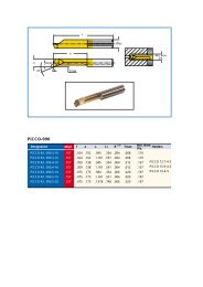
ISCAR’s family for face grooving and turning in<br />
a diameter range of 8 <str<strong>on</strong>g>to</str<strong>on</strong>g> 17 mm for up <str<strong>on</strong>g>to</str<strong>on</strong>g> 5.5 mm<br />
grooving depth, covers the range between ISCAR’s<br />
PICCO and CHAMGROOVE <str<strong>on</strong>g>to</str<strong>on</strong>g>ols.<br />
Tool Features<br />
• Can also be used for rotating applicati<strong>on</strong>s.<br />
• Internal coolant hole, directed <str<strong>on</strong>g>to</str<strong>on</strong>g> the cutting edge.<br />
• Can be used for grooving in deep holes.<br />
• Uninterrupted chip flow <strong>on</strong> the insert rake.<br />
Face Grooving and Turning<br />
Family for Dmin 8 mm<br />
Main Index<br />
A9<br />
ISCAR
INTRODUCTION<br />
Delivering<br />
Profitability<br />
ISCAR Guarantees Results<br />
Multifuncti<strong>on</strong> groove-Turn Tools<br />
for Increased Productivity and Profitability<br />
ISCAR’s unique groove-turn <str<strong>on</strong>g>to</str<strong>on</strong>g>ols are multifuncti<strong>on</strong><br />
turning <str<strong>on</strong>g>to</str<strong>on</strong>g>ols, able <str<strong>on</strong>g>to</str<strong>on</strong>g> operate in a sequence of<br />
grooving and turning modes. Moving from turning <str<strong>on</strong>g>to</str<strong>on</strong>g><br />
grooving requires c<strong>on</strong>siderati<strong>on</strong> of the basic GRIP<br />
principle, thereby eliminating the possibility of insert<br />
breakage. The CUT-GRIP line offers a diverse range<br />
of multi-functi<strong>on</strong> turn-groove <str<strong>on</strong>g>to</str<strong>on</strong>g>ols for increased<br />
productivity and profitability.<br />
A single Modular-Grip, straight or perpendicular<br />
<str<strong>on</strong>g>to</str<strong>on</strong>g>olholder can be used for many applicati<strong>on</strong>s,<br />
which will reduce <str<strong>on</strong>g>to</str<strong>on</strong>g>oling cost and s<str<strong>on</strong>g>to</str<strong>on</strong>g>ck.<br />
Main<br />
Index<br />
A10<br />
ISCAR
B<br />
Main C<strong>on</strong>tents User Guide Index<br />
B1<br />
ISCAR
General Groove-Turn Systems<br />
Selecti<strong>on</strong> Guide..................................................................................................................................<br />
B1<br />
B4<br />
External Tools & Inserts<br />
HELI-GRIP - Tools & Inserts...........................................................................<br />
B11<br />
TOP-GRIP - Tools & inserts............................................................................<br />
B15<br />
CUT-GRIP Tools & Inserts................................................................................<br />
Tools, Adapters and Blades (short pocket)...................................................................................................<br />
Tools, Adapters and Blades ( l<strong>on</strong>g pocket) ...................................................................................................<br />
Utility Inserts....................................................................................................................................................<br />
Precisi<strong>on</strong> Ground Inserts................................................................................................................................<br />
B18<br />
B18<br />
B26<br />
B29<br />
B35<br />
Inserts for Specific Applicati<strong>on</strong>s and Materials........................................<br />
Cast Ir<strong>on</strong>..........................................................................................................................................................<br />
Hardened Steel................................................................................................................................................<br />
High Temperature Alloys.................................................................................................................................<br />
Aluminum.........................................................................................................................................................<br />
Next <str<strong>on</strong>g>to</str<strong>on</strong>g> Shoulder.............................................................................................................................................<br />
Undercutting....................................................................................................................................................<br />
Pulley V Grooves.............................................................................................................................................<br />
T/L Grooves....................................................................................................................................................<br />
B44<br />
B45<br />
B46<br />
B47<br />
B48<br />
B49<br />
B50<br />
B51<br />
GDMW Tools and Inserts.................................................................................<br />
B53<br />
Multi-Corner Grooving Tools and Inserts....................................................<br />
PENTACUT (5 cutting edges)..........................................................................................................................<br />
GTGA (3 cutting edges)..................................................................................................................................<br />
B54<br />
B62<br />
Tools and Inserts for Heavy Duty Grooving and Turning.........................<br />
B64<br />
Main User Guide Index<br />
B2<br />
ISCAR
Internal Tools and Inserts...........................................................<br />
GEHIR Boring Bars Dmin 12.5 mm (GEPI inserts).........................................................................................<br />
GHIR Boring Bars Dmin 20 mm (GIPI/GIFI/GINI inserts)..............................................................................<br />
TOP-GRIP Boring Bars Dmin 20.5 mm..........................................................................................................<br />
GHIR Boring Bars Dmin 64 mm (GDMY/F/N 8 mm inserts)..........................................................................<br />
HELI-GRIP Boring Bars Dmin 26 mm............................................................................................................<br />
CUT-GRIP Blades Dmin 70 mm......................................................................................................................<br />
Tools for Swiss-Type and Small Lathe Machines<br />
B72<br />
B80<br />
B91<br />
B93<br />
B93<br />
B94<br />
B99<br />
External Tools and Inserts<br />
SWISSCUT............................................................................................................<br />
B99<br />
CUT-GRIP.............................................................................................................<br />
B102<br />
Internal Boring Bars and Inserts...............................................................................<br />
B105<br />
PICCO (Dmin 0.6 mm).......................................................................................<br />
B105<br />
MINICHAM (Dmin 4 mm)..................................................................................<br />
B117<br />
MINCUT (Dmin 8 mm).......................................................................................<br />
B118<br />
CHAMGROOVE (Dmin 8 mm)...........................................................................<br />
B120<br />
Form Tools<br />
Broaching Tools<br />
USER GUIDE...........................................................................................................................................<br />
B125<br />
B128<br />
B132<br />
Main User Guide Index<br />
B3<br />
ISCAR
Selecti<strong>on</strong> Guide<br />
Necessary Informati<strong>on</strong> in Order <str<strong>on</strong>g>to</str<strong>on</strong>g> Select the Correct Insert<br />
ISCAR has a huge variety of groove-turn products.<br />
In many cases your operati<strong>on</strong> can be performed<br />
using several different products. In order <str<strong>on</strong>g>to</str<strong>on</strong>g> make<br />
the optimal selecti<strong>on</strong>, these basic parameters need<br />
<str<strong>on</strong>g>to</str<strong>on</strong>g> be defined:<br />
• Insert width [W]<br />
• Necessary <str<strong>on</strong>g>to</str<strong>on</strong>g>lerance <strong>on</strong> the insert<br />
• Maximum depth of grooving [T max]<br />
• If the applicati<strong>on</strong> will require grooving and<br />
turning, or <strong>on</strong>ly grooving (E-Type or not)<br />
According <str<strong>on</strong>g>to</str<strong>on</strong>g> these parameters:<br />
• Select the most suitable product<br />
according <str<strong>on</strong>g>to</str<strong>on</strong>g> the tables <strong>on</strong> pages (B5-6)<br />
• Select the most suitable chipformer<br />
according <str<strong>on</strong>g>to</str<strong>on</strong>g> the informati<strong>on</strong> <strong>on</strong> pages (B7-10)<br />
Utility Inserts<br />
Pressed <str<strong>on</strong>g>to</str<strong>on</strong>g> Size Inserts<br />
Width ± 0.05<br />
Repeatability ± 0.10<br />
Precisi<strong>on</strong> Grooving Inserts<br />
Peripheral Ground Inserts<br />
Width ± 0.02<br />
Repeatability ± 0.025<br />
±0.10<br />
±0.025<br />
W±0.05<br />
W<br />
W±0.02 W<br />
If you d<strong>on</strong>’t need the tight <str<strong>on</strong>g>to</str<strong>on</strong>g>lerance, save m<strong>on</strong>ey and<br />
select a utility (less expensive) insert.<br />
What is an E-type Groove-Turn Insert?<br />
E-type inserts are precisi<strong>on</strong> ground grooving inserts<br />
with turning capability.<br />
These inserts include the letter E in their descripti<strong>on</strong>.<br />
(example: GIP 3.00E-0.4). This is <str<strong>on</strong>g>to</str<strong>on</strong>g> distinguish them<br />
from precisi<strong>on</strong> ground inserts which are not suitable<br />
for turning operati<strong>on</strong>s that d<strong>on</strong>’t include an E in their<br />
descripti<strong>on</strong>. (example: GIP 3.00-0.2)<br />
Precisi<strong>on</strong><br />
Grooving<br />
Insert<br />
• E-type inserts have usually a larger corner radius<br />
• E-type inserts have a larger h<strong>on</strong>ing size<br />
E-Type<br />
Groove-Turn<br />
Main C<strong>on</strong>tents User Guide Index<br />
B4<br />
ISCAR
External Groove-Turn Insert Type<br />
Selecti<strong>on</strong> Guide<br />
Properties<br />
Insert<br />
Precisi<strong>on</strong> Ground<br />
Utility<br />
No. of<br />
Cutting Edges<br />
Opti<strong>on</strong> for Turning<br />
W<br />
range Tmax Page<br />
PENTACUT<br />
Size 24<br />
5 0.5-3.18 1-6.5 B57-59<br />
PENTACUT<br />
Size 34<br />
5 1.5-4.0 5-10 B60-61<br />
HELI-GRIP 2 3-6.35 No Depth Limit B14<br />
TOP-GRIP 2 3-6.35 10.5-18.6 B17<br />
Short<br />
Pocket<br />
1 3-12 No Depth Limit B35-48<br />
Short<br />
Pocket<br />
2<br />
*<br />
0.5-11.0 13** B29, B35-48<br />
L<strong>on</strong>g<br />
Pocket<br />
2<br />
*<br />
8.0 26 B30-34, B47<br />
L<strong>on</strong>g<br />
Pocket<br />
2 8.0-11.0 26<br />
B29, B35,<br />
B43-44, B48<br />
SUMO-GRIP 1 8-12 No Depth Limit B67<br />
HEAVY<br />
DUTY<br />
TIGER 1 14-20 No Depth Limit B69-70<br />
* Not <strong>on</strong> all the products<br />
** On most items<br />
Main C<strong>on</strong>tents User Guide Index<br />
B5<br />
ISCAR
Internal Groove-Turn Insert Type<br />
Selecti<strong>on</strong> Guide<br />
Tool<br />
Insert<br />
Utility<br />
Precisi<strong>on</strong><br />
Dmin Tmax W Page<br />
PICCO/<br />
MG PCO<br />
PICCO 2.0-7.0 0.4-2.5 0.5-2 B108-116<br />
MG/MGCH GIRQ 8 8.0 0.7-1.5 0.5-4<br />
B121,<br />
B124<br />
MG/MGCH GIQR 11 11.0 1.5-2.3 0.75-5<br />
B122,<br />
B124<br />
MGCH GIQR 11-15 15.0 6.3 1-3 B123<br />
GEHIR/L<br />
GEPI/<br />
GEMI<br />
12.5-16 2.4-3.0 1-3.18 B77-79<br />
GHIR/L<br />
GIFI/GIPI/<br />
GINI/GIMIY<br />
20-49 2.5-8.0 1.53-6.35 B85-90<br />
TGIR/L TGMF 20.5-57 5.5-17.5 3-6.35 B17<br />
HELIIR/L GRIP 26-53 5-12 3-6.35 B14<br />
GHIR/L 40-8<br />
GDMF/<br />
GDMY/<br />
GDMN...<br />
65 15-20 8-11 B29-48<br />
GHIC/CGHN<br />
GIP/GIF/<br />
GIMN/GIMF/<br />
GIA...<br />
70-250 10-26 2.8-6.35 B29-48<br />
Main C<strong>on</strong>tents User Guide Index<br />
B6<br />
ISCAR
Selecti<strong>on</strong> Guide<br />
Chipbreaker Selecti<strong>on</strong><br />
General Use<br />
P-Type<br />
• Very “open” geometry<br />
• Medium <str<strong>on</strong>g>to</str<strong>on</strong>g> high feed in turning<br />
& grooving<br />
• Large variety of standard sizes<br />
• Precisi<strong>on</strong> ground inserts <strong>on</strong>ly<br />
• Width range<br />
External: 2.39 - 6.35 mm<br />
Internal: 2.39 - 6.35 mm<br />
F-Type<br />
• First choice in grooving<br />
• Low <str<strong>on</strong>g>to</str<strong>on</strong>g> medium feeds in grooving & turning<br />
• Both precisi<strong>on</strong> ground and utility inserts<br />
• Width range<br />
External: 3.0 - 10 mm<br />
Internal: 3 - 6 mm<br />
G-Type<br />
• Efficient chipbreaker for narrow<br />
width grooves<br />
• Width range: 1 - 2.3 mm<br />
• No opti<strong>on</strong> for turning<br />
Y-Type<br />
• General use in grooving & turning<br />
• Positive <str<strong>on</strong>g>to</str<strong>on</strong>g>p rake reduces cutting forces<br />
• Excellent for l<strong>on</strong>g shafts<br />
• Eliminates vibrati<strong>on</strong>s<br />
• Both precisi<strong>on</strong> ground and utility inserts<br />
• Width range<br />
External: 8 - 20 mm<br />
HG-Y-Type<br />
• General use in grooving & turning<br />
• Efficient for a wide range of materials<br />
and cutting c<strong>on</strong>diti<strong>on</strong>s<br />
• Utility inserts <strong>on</strong>ly<br />
• Width range<br />
External: 3 - 6.35 mm<br />
Internal: 3 - 6.35 mm<br />
Main C<strong>on</strong>tents User Guide Index<br />
B7<br />
ISCAR
Selecti<strong>on</strong> Guide<br />
Chipbreaker Selecti<strong>on</strong><br />
Problematic and Specific Materials<br />
N-Type<br />
• First choice in grooving of problematic,<br />
soft & gummy materials<br />
• Very low <str<strong>on</strong>g>to</str<strong>on</strong>g> medium feeds<br />
(from 0.05 mm/rev)<br />
• Both precisi<strong>on</strong> ground and utility inserts<br />
• Opti<strong>on</strong> for turning<br />
• Width range<br />
External: 3 - 8 mm<br />
Internal: 3 - 5 mm<br />
M-Type<br />
• Unique chipbreaker with splitter<br />
Chips are split in<str<strong>on</strong>g>to</str<strong>on</strong>g> 3 Segments<br />
• Efficient for problematic,<br />
soft & gummy materials<br />
• Opti<strong>on</strong> for light turning<br />
• Width - 8 mm<br />
A-Type<br />
• First choice for machining cast Ir<strong>on</strong><br />
• Peripheral 15° T-land <strong>on</strong> a flat <str<strong>on</strong>g>to</str<strong>on</strong>g>p<br />
• Exerts high cutting forces, therefore<br />
suitable for stable c<strong>on</strong>diti<strong>on</strong>s<br />
• Precisi<strong>on</strong> ground inserts <strong>on</strong>ly<br />
• Width range<br />
External: 3 - 8 mm<br />
PA-Type<br />
• First choice for machining aluminum<br />
• High positive rake<br />
• Peripheral ground and polished <str<strong>on</strong>g>to</str<strong>on</strong>g>p rake<br />
with a very sharp edge<br />
• Suitable also for finish operati<strong>on</strong>s <strong>on</strong><br />
titanium and heat resistant alloys<br />
• Width range<br />
External: 3 - 8 mm<br />
CW-Type<br />
• Unique chipformer for heavy-duty grooving<br />
• Very wide chipbreaking range <strong>on</strong> carb<strong>on</strong><br />
and alloy steel<br />
• Width range 14 & 17 mm<br />
Main C<strong>on</strong>tents User Guide Index<br />
B8<br />
ISCAR
Selecti<strong>on</strong> Guide<br />
Chipbreaker Selecti<strong>on</strong><br />
Profiling (Full radius)<br />
Y-Type<br />
• First choice in profiling.<br />
• Positive <str<strong>on</strong>g>to</str<strong>on</strong>g>p rake reduces<br />
cutting forces.<br />
• Excellent for l<strong>on</strong>g shafts.<br />
• Eliminates vibrati<strong>on</strong>s.<br />
• Both precisi<strong>on</strong> ground and<br />
utility inserts.<br />
• Width range<br />
External: 3 - 12 mm.<br />
YF-Type<br />
• First choice for profiling<br />
ductile materials<br />
• Utility inserts <strong>on</strong>ly.<br />
• Width range<br />
External: 3 - 8 mm.<br />
PA-Type<br />
• First choice for profiling aluminum.<br />
• High positive rake.<br />
• Peripheral ground and polished <str<strong>on</strong>g>to</str<strong>on</strong>g>p<br />
rake with a very sharp edge.<br />
• Suitable also for finish operati<strong>on</strong>s <strong>on</strong><br />
titanium and heat resistant alloys.<br />
• Width range<br />
External: 3 - 8 mm.<br />
YZ-Type<br />
• First choice for profiling ductile aluminum.<br />
• Peripheral ground and polished <str<strong>on</strong>g>to</str<strong>on</strong>g>p<br />
rake with a very sharp edge.<br />
• Width range<br />
External: 3 - 8 mm.<br />
H-Type<br />
• Unique chipbreaker for heavy-duty profiling.<br />
• Negative T-land for extra edge <str<strong>on</strong>g>to</str<strong>on</strong>g>ughness<br />
• Suitable for heavy interrupted cuts and<br />
cast ir<strong>on</strong> machining.<br />
• Width 12 mm<br />
Main C<strong>on</strong>tents User Guide Index<br />
B9<br />
ISCAR
Selecti<strong>on</strong> Guide<br />
Chipbreaker Width Range<br />
External<br />
Insert Width<br />
12 20<br />
11<br />
10<br />
9<br />
8<br />
7<br />
6 6.35 6.35<br />
5<br />
4<br />
3 3.48<br />
2 2.3 2.39<br />
1<br />
G P F Y N HG-Y M A PA<br />
Internal<br />
Insert Width<br />
7<br />
6 6.35 6.35<br />
5<br />
4<br />
3<br />
2 2.39<br />
1<br />
P F N HG-Y<br />
Suitable Chipbreaker and Required Feed Range for Workpiece Material<br />
High<br />
Alloy Steel<br />
Austenitic<br />
Stainless<br />
High Temp.<br />
Alloys<br />
N<strong>on</strong>ferrous<br />
Materials<br />
Cast Ir<strong>on</strong><br />
P P P<br />
HG-Y HG-Y Y PA* A*<br />
Feed<br />
Y Y F P P<br />
F F PA (finish <strong>on</strong>ly) HG<br />
Low<br />
* First Choice<br />
N<br />
F<br />
Main C<strong>on</strong>tents User Guide Index<br />
B10<br />
ISCAR
HELI-GRIP - Tools & Inserts<br />
HELIR/L<br />
External Holders for Turning, Grooving and Parting<br />
2<br />
Tmax-r 1<br />
l2<br />
Dmax<br />
A<br />
h<br />
h4<br />
l1<br />
h<br />
W<br />
b<br />
Tmax-r<br />
f<br />
Right-hand shown<br />
Designati<strong>on</strong> W min W max Tmax-r (2) Fig D max (3) h b f l1 l2 A h4 Inserts<br />
HELIR/L 1212-3T12 3.00 3.18 12.00 1 - 12.0 12.0 10.0 135.00 30.0 2.40 3.0 GRIP-3..., HG.-3<br />
HELIR/L 1616-3T12 3.00 3.18 12.00 1 - 16.0 16.0 14.8 135.00 30.0 2.40 - GRIP-3..., HG.-3<br />
HELIR/L 2020-3T12 3.00 3.18 12.00 1 - 20.0 20.0 18.8 135.00 29.0 2.40 - GRIP-3..., HG.-3<br />
HELIR/L 2525-3T12 3.00 3.18 12.00 1 - 25.0 25.0 23.8 135.00 29.0 2.40 - GRIP-3..., HG.-3<br />
HELIR/L 1616-4T12 4.00 4.76 12.00 1 - 16.0 16.0 14.4 135.00 29.0 3.20 4.0 GRIP-4..., DG.-4<br />
HELIR/L 2020-4T12 4.00 4.76 12.00 1 - 20.0 20.0 18.4 135.00 29.0 3.20 - GRIP-4..., DG.-4<br />
HELIR/L 2525-4T12 4.00 4.76 12.00 1 - 25.0 25.0 23.4 135.00 29.0 3.20 - GRIP-4..., DG.-4<br />
HELIR/L 2020-5T12 5.00 5.00 12.00 1 - 20.0 20.0 17.9 135.00 29.0 4.20 - GRIP-5..., DG.-5<br />
HELIR/L 2525-5T12 5.00 5.00 12.00 1 - 25.0 25.0 22.9 135.00 29.0 4.20 - GRIP-5..., DG.-5<br />
HELIR/L 2525-6T12 6.00 6.35 12.00 1 - 25.0 25.0 22.4 135.00 29.0 5.20 - GRIP-6..., DG.-6<br />
HELIR/L 1616-3T20 (1) 3.00 3.18 - 2 40.0 16.0 16.0 14.8 140.00 36.4 2.40 - GRIP-3..., HG.-3<br />
HELIR/L 2020-3T20 (1) 3.00 3.18 - 2 40.0 20.0 20.0 18.8 140.00 36.4 2.40 - GRIP-3..., HG.-3<br />
HELIR/L 2525-3T20 (1) 3.00 3.18 - 2 40.0 25.0 25.0 23.8 140.00 36.4 2.40 - GRIP-3..., HG.-3<br />
HELIR/L 3232-3T20 (1) 3.00 3.18 - 2 40.0 32.0 32.0 30.8 150.00 36.4 2.40 - GRIP-3..., HG.-3<br />
HELIR/L 1616-4T20 4.00 4.76 - 2 40.0 16.0 16.0 14.4 140.00 38.0 3.20 4.0 GRIP-4..., DG.-4<br />
HELIR/L 2020-4T25 4.00 4.76 - 2 50.0 20.0 20.0 18.4 140.00 42.0 3.20 - GRIP-4..., DG.-4<br />
HELIR/L 2525-4T25 4.00 4.76 - 2 50.0 25.0 25.0 23.4 140.00 42.0 3.20 - GRIP-4..., DG.-4<br />
HELIR/L 3232-4T25 4.00 4.76 - 2 50.0 32.0 32.0 30.4 150.00 43.0 3.20 - GRIP-4..., DG.-4<br />
HELIR/L 2020-5T25 5.00 5.00 - 2 50.0 20.0 20.0 17.9 140.00 42.0 4.20 - GRIP-5..., DG.-5<br />
HELIR/L 2525-5T25 5.00 5.00 - 2 50.0 25.0 25.0 22.9 140.00 42.0 4.20 - GRIP-5..., DG.-5<br />
HELIR/L 3232-5T25 5.00 5.00 - 2 50.0 32.0 32.0 29.9 150.00 43.0 4.20 - GRIP-5..., DG.-5<br />
HELIR/L 2525-6T30 6.00 6.35 - 2 60.0 25.0 25.0 22.4 140.00 51.4 5.20 - GRIP-6..., DG.-6<br />
HELIR/L 3232-6T30 6.00 6.35 - 2 60.0 32.0 32.0 29.4 150.00 51.4 5.20 - GRIP-6..., DG.-6<br />
• For <str<strong>on</strong>g>to</str<strong>on</strong>g>ol type as shown in Fig.2, Tmax for grooving is limited by the part diameter D, for grooving depth capacity, see table below<br />
• For user guide, see pages B132-145<br />
(1) DGN inserts are not suitable for this <str<strong>on</strong>g>to</str<strong>on</strong>g>ol. (2) Does not depend <strong>on</strong> the workpiece diameter (3) Maximum parting diameter<br />
For inserts, see pages: GRIP (B14) • GRIP (Full Radius) (B14) • DGN/DGNC/DGNM-C (D24) • HGN-C (D30) • DGR/L-C DGRC/LC-C (D24)<br />
• DGN/DGNM-J/JS/JT (D25) • HGN-J (D30) • DGR/L-J/JS (D26) • DGN-UT/UA (D27) • DGN-W (D25) • HGN-UT (D31).<br />
Spare Parts<br />
Designati<strong>on</strong> Screw Key<br />
HELIR/L 1212-3T12 SR M5X16DIN912 HW 4.0<br />
HELIR/L 1616-3T12 SR M5X16DIN912 HW 4.0<br />
HELIR/L 2020-3T12 SR M5X16DIN912 HW 4.0<br />
HELIR/L 2525-3T12 SR M5X16DIN912 HW 4.0<br />
HELIR/L 1616-4T12 SR M5X16DIN912 HW 4.0<br />
HELIR/L 2020-4T12 SR M5X16DIN912 HW 4.0<br />
HELIR/L 2525-4T12 SR M5X16DIN912 HW 4.0<br />
HELIR/L 2020-5T12 SR M6X16DIN912 HW 5.0<br />
HELIR/L 2525-5T12 SR M6X16DIN912 HW 5.0<br />
HELIR/L 2525-6T12 SR M6X16DIN912 HW 5.0<br />
HELIR/L 1616-3T20 SR M6X20DIN912 HW 5.0<br />
HELIR/L 2020-3T20 SR M6X20DIN912 HW 5.0<br />
HELIR/L 2525-3T20 SR M6X20DIN912 HW 5.0<br />
HELIR/L 3232-3T20 SR M6X20DIN912 HW 5.0<br />
HELIR/L 1616-4T20 SR M6X20DIN912 HW 5.0<br />
HELIR/L 2020-4T25 SR M6X20DIN912 HW 5.0<br />
HELIR/L 2525-4T25 SR M6X20DIN912 HW 5.0<br />
HELIR/L 3232-4T25 SR M6X20DIN912 HW 5.0<br />
HELIR/L 2020-5T25 SR M6X20DIN912 HW 5.0<br />
HELIR/L 2525-5T25 SR M6X20DIN912 HW 5.0<br />
HELIR/L 3232-5T25 SR M6X20DIN912 HW 5.0<br />
HELIR/L 2525-6T30 SR M6X20DIN912 HW 5.0<br />
HELIR/L 3232-6T30 SR M6X20DIN912 HW 5.0<br />
Depth Capacity<br />
Designati<strong>on</strong><br />
HELIR/L 1616-3T20 — — — — — 80 194 ∞ ∞ ∞ ∞ ∞ ∞<br />
HELIR/L 2020-3T20 — — — — — 80 123 299 ∞ ∞ ∞ ∞ ∞<br />
HELIR/L 2525-3T20 — — — — — 79 99 136 229 815 ∞ ∞ ∞<br />
HELIR/L 3232-3T20 — — — — — 79 89 103 127 169 261 604 ∞<br />
HELIR/L 1616-4T20 — — — — — 78 132 505 ∞ ∞ ∞ ∞ ∞<br />
HELIR/L 2020-4T25 — — 98 185 ∞ ∞ ∞ ∞ ∞ ∞ ∞ ∞ ∞<br />
HELIR/L 2525-4T25 — — 98 136 233 368 ∞ ∞ ∞ ∞ ∞ ∞ ∞<br />
HELIR/L 3232-4T25 — — 98 — 149 175 270 626 ∞ ∞ ∞ ∞ ∞<br />
HELIR/L 2020-5T25 — — 98 182 ∞ ∞ ∞ ∞ ∞ ∞ ∞ ∞ ∞<br />
HELIR/L 2525-5T25 — — 98 136 233 368 ∞ ∞ ∞ ∞ ∞ ∞ ∞<br />
HELIR/L 3232-5T25 — — 98 — 149 175 270 626 ∞ ∞ ∞ ∞ ∞<br />
HELIR/L 2525-6T30 98 135 354 ∞ ∞ ∞ ∞ ∞ ∞ ∞ ∞ ∞ ∞<br />
HELIR/L 3232-6T30 98 121 194 345 1718 ∞ ∞ ∞ ∞ ∞ ∞ ∞ ∞<br />
Depth T 30.0 28.0 25.0 23.0 21.0 20.0 18.0 16.0 14.0 12.0 10.0 8.0 6.5<br />
D<br />
Main C<strong>on</strong>tents User Guide Index<br />
B11<br />
ISCAR
HGPAD<br />
Adapters for Turning, Grooving and Parting<br />
HOLDER:<br />
MAHPR<br />
B1<br />
h1<br />
f1<br />
l2<br />
f<br />
l1<br />
Tmax-r<br />
f2<br />
HOLDER: MAHL<br />
A2<br />
A<br />
W<br />
Left-hand shown • f=f1(shank)+f2(adapter)<br />
Designati<strong>on</strong> W min W max Tmax-r l2 f2 A A2 l1 B1 h1 Inserts<br />
HGPAD 3R/L-T12 3.00 3.00 12.00 15.2 4.80 2.50 6.0 39.70 32.0 24.0 GRIP 3, HGN 3<br />
HGPAD 3R/L-T20 3.00 3.00 20.00 21.2 4.80 2.50 6.0 45.70 32.0 24.0 GRIP 3, HGN 3<br />
HGPAD 4R/L-T12 4.00 4.76 12.00 18.7 4.40 3.30 6.0 43.20 32.0 24.0 GRIP 4, DGN 4<br />
HGPAD 4R/L-T20 4.00 4.76 20.00 21.2 4.40 3.30 6.0 45.70 32.0 24.0 GRIP 4, DGN 4<br />
HGPAD 5R/L-T12 5.00 5.00 12.00 18.7 3.90 4.20 6.0 43.20 32.0 24.0 GRIP 5, DGN 5<br />
HGPAD 5R/L-T20 5.00 5.00 20.00 21.2 3.90 4.20 6.0 45.70 32.0 24.0 GRIP 5, DGN 5<br />
HGPAD 6R/L-T12 6.00 6.35 12.00 18.7 3.40 5.20 6.0 43.20 32.0 24.0 GRIP 6, DGN 6<br />
HGPAD 6R/L-T22 6.00 6.35 22.00 23.2 3.40 5.20 6.0 47.70 32.0 24.0 GRIP 6, DGN 6<br />
• DO-GRIP DGN, HGN inserts can be used for grooving <strong>on</strong>ly • For user guide, see pages B132-145.<br />
For inserts, see pages: GRIP (B14) • GRIP (Full Radius) (B14) • DGN/DGNC/DGNM-C (D24) • HGN-C (D30) • DGN/DGNM-J/JS/JT (D25) • HGN-J (D30) •<br />
DGN-UT/UA (D27) • DGN-W (D25) • HGN-UT (D31).<br />
For holders, see pages: MAHPR/L (B22) • MAHR/L (B22) • C#‐MAHD (G7) • C#‐MAHDOR (G5) • C#‐MAHDR‐45 (G4) • C#‐MAHPD (G7) • C#‐MAHUR/L (G5)<br />
• HSK A63WH‐MAHDOR (G17) • HSK A63WH‐MAHDR‐45 (G16) • HSK A63WH‐MAHUR/L (G17) • IM‐MAHD (G26) • IM‐MAHPD (G27) • IM63 XMZ MAHDOR<br />
(G24) • IM63 XMZ MAHDR‐45 (G23) • IM63 XMZ MAHUR/L (G25)..<br />
l<br />
HGFH<br />
Parting and Grooving Blades for 3 mm GRIP Inserts<br />
W<br />
T<br />
W<br />
D<br />
h1<br />
B1<br />
l1<br />
150°<br />
A<br />
Designati<strong>on</strong> B1 W A l1 h1 T blade<br />
HGFH 26-3 26.0 3.00 2.40 110.00 21.4 37.5<br />
HGFH 32-3 32.0 3.00 2.40 150.00 24.8 50.0<br />
For inserts, see pages: GRIP (B14) • GRIP (Full Radius) (B14) • HGN-C (D30) • HGR/L-C (D30) • HGN-J (D30) • HGN-UT (D31) • HGR/L-J/JS (D31).<br />
For holders, see pages: C#-TBK-R/L (G6) • HSK A63WH-TBK-R/L (G18) • IM63 XMZ TBK (G25) • SGTBF (F4) • SGTBR/L (F3) • SGTBU/SGTBN (F2) •<br />
UBHCR/L (F4).<br />
Spare Parts<br />
Designati<strong>on</strong><br />
Extrac<str<strong>on</strong>g>to</str<strong>on</strong>g>r<br />
HGFH EDG 23B*<br />
* Opti<strong>on</strong>al, should be ordered separately<br />
Main C<strong>on</strong>tents User Guide Index<br />
B12<br />
ISCAR
l<br />
DGFH<br />
Parting and Grooving Blades with and without Coolant Holes for DO-GRIP<br />
and HELI-GRIP Inserts<br />
Dmax<br />
W<br />
h1<br />
W<br />
D<br />
DGFH<br />
DGFH-C<br />
l1<br />
A<br />
150°<br />
B1<br />
Designati<strong>on</strong> B1 W min W max A l1 h1 D max Inserts<br />
DGFH 32-4 32.0 4.00 4.00 3.20 150.00 24.8 100.0 DG. 4.../GRIP 4...<br />
DGFH 32C-4 (1) 32.0 4.00 4.00 3.20 150.00 24.8 69.0 DG. 4..C<br />
DGFH 32-5 32.0 5.00 5.00 4.00 150.00 24.8 120.0 DG. 5.../GRIP 5...<br />
DGFH 32-6 32.0 6.00 6.35 5.20 150.00 24.8 120.0 DG. 6.../GRIP 6...<br />
DGFH 45-3 45.0 3.00 (4) 3.18 2.40 225.00 38.0 160.0 DG. 3.../DG. 1...<br />
DGFH 45-4 45.0 4.00 4.10 3.20 225.00 38.0 160.0 DG. 4.../GRIP 4...<br />
DGFH 45-5 45.0 4.80 5.00 4.00 225.00 38.0 160.0 DG. 5.../GRIP 5...<br />
DGFH 45-6 45.0 6.00 6.40 5.20 225.00 38.0 160.0 DG. 6.../GRIP 6...<br />
• DG..1.0 insert can be mounted in<str<strong>on</strong>g>to</str<strong>on</strong>g> pocket sizes 2 and 3. In that case the pocket width has <str<strong>on</strong>g>to</str<strong>on</strong>g> be modified - see page<br />
(1) These blades are suitable for turning, using GRIP 4 inserts • Blades with fr<strong>on</strong>tal coolant holes (JET-CUT)<br />
• For user guide, see pages B132-145.<br />
For inserts, see pages: DGN/DGNC/DGNM-C (D24) • DGR/L-C DGRC/LC-C (D24) • DGN/DGNM-J/JS/JT (D25) • DGR/L-J/JS (D26) • DGN-P (D28) • DGN-UT/<br />
UA (D27) • DGN-W (D25) • DGN-WP (D29) • DGN-Z (D26) • DGR-WP (D29) • DGR/L-P (D28) • DGR/L-Z/ZS (D27) • GRIP (B14) • GRIP (Full Radius) (B14).<br />
For holders, see pages: C#-TBK-R/L (G6) • HSK A63WH-TBK-R/L (G18) • IM63 XMZ TBK (G25) • SGTBF (F4) • SGTBR/L (F3) • SGTBU/SGTBN (F2) •<br />
UBHCR/L (F4).<br />
Spare Parts<br />
Designati<strong>on</strong> Extrac<str<strong>on</strong>g>to</str<strong>on</strong>g>r Male C<strong>on</strong>n. Cooling Tube<br />
DGFH 32-4 EDG 33A*<br />
DGFH 32C-4 EDG 33A* CM 343 MALE CONN.* SGCU 341*<br />
DGFH 32-5 EDG 33A*<br />
DGFH 32-6 EDG 33A*<br />
DGFH 45-3 EDG 33A*<br />
DGFH 45-4 EDG 33A*<br />
DGFH 45-5 EDG 33A*<br />
DGFH 45-6 EDG 33A*<br />
* Opti<strong>on</strong>al, should be ordered separately<br />
Main C<strong>on</strong>tents User Guide Index<br />
B13<br />
ISCAR
GRIP<br />
Utility Double-Ended Inserts, for External,<br />
Internal and Face Machining<br />
±0.1<br />
lRef.<br />
R<br />
W<br />
M<br />
No depth penetrati<strong>on</strong> limit<br />
Dimensi<strong>on</strong>s Tough Ö Hard Recommended Machining Data<br />
IC830<br />
ap f turn f groove<br />
Designati<strong>on</strong> W ±0.05 R ±0.05 l M<br />
(mm) (mm/rev) (mm/rev)<br />
GRIP 3002Y 3.00 0.20 16.00 2.3 l l l l l 0.25-1.80 0.14-0.18 0.07-0.11<br />
GRIP 3003Y 3.00 0.30 16.00 2.3 l l l l l 0.40-1.80 0.15-0.19 0.07-0.11<br />
GRIP 318-040Y 3.18 0.40 16.00 2.3 l l l l l 0.50-1.90 0.17-0.22 0.07-0.12<br />
GRIP 4002Y 4.00 0.20 19.00 2.8 l l l l l 0.25-2.40 0.16-0.21 0.09-0.14<br />
GRIP 4004Y 4.00 0.40 19.00 2.8 l l l l l l l 0.50-2.40 0.18-0.24 0.09-0.15<br />
GRIP 476-080Y 4.76 0.80 19.00 3.1 l l l l l 1.00-2.80 0.21-0.33 0.10-0.20<br />
GRIP 5005Y 5.00 0.50 19.00 3.3 l l l l l l l 0.60-3.00 0.20-0.30 0.11-0.20<br />
GRIP 5008Y 5.00 0.80 19.00 3.4 l l l l l l l 1.00-3.00 0.23-0.35 0.11-0.21<br />
GRIP 6005Y 6.00 0.50 19.00 4.2 l l l l l l l 0.60-3.60 0.22-0.36 0.13-0.23<br />
GRIP 6008Y 6.00 0.80 19.00 4.2 l l l l l l l 1.00-3.60 0.24-0.42 0.13-0.25<br />
GRIP 635-080Y 6.35 0.80 19.00 4.2 l l l l l 1.00-3.80 0.25-0.44 0.14-0.27<br />
• For cutting speed recommendati<strong>on</strong>s and user guide, see pages B132-145.<br />
For <str<strong>on</strong>g>to</str<strong>on</strong>g>ols, see pages: C#-HELIR/L (G10) • C#-HFIR/L-MC (G12) • CR HFIR/L-M (E34) • DGAD/HGAD (D22) • DGFH (B13) • DGFS (D12) • DGTR/L (D18) •<br />
HELIIR/L (B93) • HELIR/L (B11) • HFAER/L-4T (E24) • HFAER/L-5,6T (E25) • HFAIR/L-4T (E30) • HFAIR/L-5,6T (E32) • HFFR/L-T (E22) • HFHR/L-4T (E18) •<br />
HFHR/L-5T (E19) • HFIR/L-MC (E33) • HFPAD-3 (E20) • HFPAD-4 (E21) • HFPAD-5 (E21) • HFPAD-6 (E22) • HGAER/L-3 (E24) • HGAIR/L-3 (E30) • HGFH (B12)<br />
• HGHR/L-3 (E16) • HGPAD (B12) • IM-HFIR/L-MC (G29).<br />
IC8250<br />
IC418<br />
IC808<br />
IC908<br />
IC5010<br />
IC807<br />
GRIP (Full Radius)<br />
Utility Double-Ended Full Radius Inserts, for External,<br />
Internal and Face Machining<br />
±0.1<br />
lRef.<br />
7°<br />
R<br />
M<br />
W<br />
No depth penetrati<strong>on</strong> limit.<br />
Dimensi<strong>on</strong>s Tough Ö Hard Recommended Machining Data<br />
IC830<br />
ap f turn f groove<br />
Designati<strong>on</strong> W ±0.05 R ±0.05 l M<br />
(mm) (mm/rev) (mm/rev)<br />
GRIP 3015Y 3.00 1.50 16.00 2.1 l l l l l l l 0.00-1.50 0.18-0.26 0.07-0.13<br />
GRIP 318-159Y 3.18 1.59 16.00 2.3 l l 0.00-1.50 0.19-0.28 0.07-0.13<br />
GRIP 4020Y 4.00 2.00 19.00 2.8 l l l l l l l 0.00-2.00 0.20-0.34 0.09-0.17<br />
GRIP 476-238Y 4.76 2.38 19.00 3.2 l l l 0.00-2.30 0.21-0.40 0.10-0.20<br />
GRIP 5025Y 5.00 2.50 19.00 3.4 l l l l l l l 0.00-2.50 0.23-0.42 0.11-0.21<br />
GRIP 6030Y 6.00 3.00 19.00 4.2 l l l l l l l 0.00-3.00 0.24-0.50 0.13-0.25<br />
GRIP 635-318Y 6.35 3.18 19.00 4.0 l l 0.00-3.10 0.25-0.53 0.14-0.27<br />
• For cutting speed recommendati<strong>on</strong>s and user guide, see pages B132-145.<br />
For <str<strong>on</strong>g>to</str<strong>on</strong>g>ols, see pages: C#-HELIR/L (G10) • C#-HFIR/L-MC (G12) • CR HFIR/L-M (E34) • DGAD/HGAD (D22) • DGFH (B13) • DGFS (D12) • DGTR/L (D18) •<br />
HELIIR/L (B93) • HELIR/L (B11) • HFAER/L-4T (E24) • HFAER/L-5,6T (E25) • HFAIR/L-4T (E30) • HFAIR/L-5,6T (E32) • HFFR/L-T (E22) • HFHR/L-4T (E18) •<br />
HFHR/L-5T (E19) • HFIR/L-MC (E33) • HFPAD-3 (E20) • HFPAD-4 (E21) • HFPAD-5 (E21) • HFPAD-6 (E22) • HGAER/L-3 (E24) • HGAIR/L-3 (E30) • HGFH (B12)<br />
• HGHR/L-3 (E16) • HGPAD (B12) • IM-HFIR/L-MC (G29).<br />
IC8250<br />
IC418<br />
IC808<br />
IC908<br />
IC5010<br />
IC807<br />
Main C<strong>on</strong>tents User Guide Index<br />
B14<br />
ISCAR
TOP-GRIP - Tools & inserts<br />
TGDR/L<br />
External Holders for Turning, Grooving and Profiling<br />
l2<br />
l1<br />
h<br />
h<br />
h4<br />
f Tmax-r<br />
b<br />
W<br />
Right-hand shown<br />
Designati<strong>on</strong> W min W max Tmax-r h b l1 l2 f h4 Inserts<br />
TGDR/L 1616-3M 3.00 3.00 7.50 16.0 16.0 100.00 30.5 14.7 6.0 TGMF 3<br />
TGDR/L 2020-3M 3.00 3.00 7.50 20.0 20.0 125.00 30.5 18.7 - TGMF 3<br />
TGDR/L 2525-3M 3.00 3.00 7.50 25.0 25.0 140.00 30.5 23.7 - TGMF 3<br />
TGDR/L 1616-4M 4.00 5.00 9.00 16.0 16.0 100.00 32.2 14.2 6.0 TGMF 4/TGMF 5<br />
TGDR/L 2020-4M 4.00 5.00 9.00 20.0 20.0 125.00 32.2 18.2 6.0 TGMF 4/TGMF 5<br />
TGDR/L 2525-4M 4.00 5.00 15.50 25.0 25.0 140.00 34.0 23.2 - TGMF 4/TGMF 5<br />
TGDR/L 2525-5M 5.00 5.00 18.00 25.0 25.0 140.00 37.0 22.7 - TGMF 5<br />
TGDR/L 3232-5M 5.00 5.00 22.00 32.0 32.0 150.00 45.0 29.8 - TGMF 5<br />
TGDR/L 2525-6M 6.00 6.35 22.00 25.0 25.0 150.00 43.0 22.5 - TGMF 6<br />
TGDR/L 3232-6M 6.00 6.35 22.00 32.0 32.0 150.00 43.0 29.5 - TGMF 6<br />
• For user guide, see pages B132-145.<br />
For inserts, see pages: TGMF (Full Radius) (B17) • TGMF/P (B17).<br />
Spare Parts<br />
Designati<strong>on</strong> Screw Key<br />
TGDR/L 1616-3M SR M5X16DIN912 HW 4.0<br />
TGDR/L 2020-3M SR M5X20DIN912 HW 4.0<br />
TGDR/L 2525-3M SR M5X20DIN912 HW 4.0<br />
TGDR/L 1616-4M SR M5X20DIN912 HW 4.0<br />
TGDR/L 2020-4M SR M5X20DIN912 HW 4.0<br />
TGDR/L 2525-4M SR M5X20DIN912 HW 4.0<br />
TGDR/L 2525-5M SR M5X25DIN912 HW 4.0<br />
TGDR/L 3232-5M SR M6X25DIN912 UNB. HW 5.0<br />
TGDR/L 2525-6M SR M6X25DIN912 UNB. HW 5.0<br />
TGDR/L 3232-6M SR M6X25DIN912 UNB. HW 5.0<br />
TGPAD<br />
Adapters for TGMF / TGMP Groove-Turn Inserts<br />
HOLDER: MAHPR<br />
B1<br />
h1<br />
f1<br />
l2<br />
f<br />
l1<br />
Tmax-r<br />
HOLDER: MAHL<br />
A2 A W f2<br />
Left-hand shown • f=f1(shank)+f2(adapter)<br />
Designati<strong>on</strong> W min W max Tmax-r f2 A A2 l2 l1 h1 B1<br />
TGPAD 3R/L-T9 3.00 3.00 9.00 4.00 2.40 5.2 12.7 37.20 24.0 30.0<br />
TGPAD 4R/L-T16 4.00 5.00 16.00 3.50 3.40 5.2 17.2 41.70 24.0 30.0<br />
TGPAD 5R/L-T16 5.00 5.00 16.00 3.00 4.40 5.2 17.2 41.70 24.0 30.0<br />
TGPAD 6R/L-T22 6.00 6.35 22.00 3.50 5.00 6.0 23.2 47.10 24.0 32.0<br />
• For user guide, see pages B132-145.<br />
For inserts, see pages: TGMF (Full Radius) (B17) • TGMF/P (B17).<br />
For holders, see pages: MAHPR/L (B22) • MAHR/L (B22) • C#-MAHD (G7) • C#-MAHDR-45 (G4) • C#-MAHPD (G7) • C#-MAHUR/L (G5) • HSK<br />
A63WH-MAHDOR (G17) • HSK A63WH-MAHDR-45 (G16) • HSK A63WH-MAHUR/L (G17) • IM-MAHD (G26) • IM-MAHPD (G27) • IM63 XMZ MAHDOR (G24) •<br />
IM63 XMZ MAHDR-45 (G23) • IM63 XMZ MAHUR/L (G25).<br />
Main C<strong>on</strong>tents User Guide Index<br />
B15<br />
ISCAR
TGHN-D<br />
Double-Ended Blades for Utility Grooving and Turning Inserts<br />
Tblade<br />
W<br />
h1<br />
B1<br />
l1<br />
A<br />
Designati<strong>on</strong> B1 W min W max T blmin T blade h1 l1 A Inserts<br />
TGHN 26-3D 26.0 3.00 3.00 10.0 15.0 21.4 110.00 2.40 TGMF 3<br />
TGHN 26-4D 26.0 4.00 5.00 10.0 15.0 21.4 110.00 3.20 TGMF 4, TGMF/P 5<br />
TGHN 26-5D 26.0 5.00 5.00 10.0 20.0 21.4 110.00 4.00 TGMF/P 5<br />
TGHN 32-3D 32.0 3.00 3.00 10.0 18.0 24.8 150.00 2.40 TGMF 3<br />
TGHN 32-4D 32.0 4.00 5.00 12.0 21.0 24.8 150.00 3.20 TGMF 4, TGMF/P 5<br />
TGHN 32-5D 32.0 5.00 5.00 12.0 26.0 24.8 150.00 4.00 TGMF/P 5<br />
TGHN 32-6D 32.0 6.00 6.35 16.0 26.0 24.8 150.00 5.20 TGMF 6<br />
• Use the drilled holes <strong>on</strong> blade for min. and max. overhang • When using a double-ended insert, grooving depth is limited by the insert. • For user guide, see<br />
pages B132-145.<br />
For inserts, see pages: TGMF (Full Radius) (B17) • TGMF/P (B17).<br />
For holders, see pages: SGTBU/SGTBN (F2) • UBHCR/L (F4).<br />
TGHN-S<br />
Single-Ended Blades for Utility Grooving and Turning Inserts<br />
Tblade<br />
W<br />
h1<br />
B1<br />
l1<br />
A<br />
Designati<strong>on</strong> B1 W min W max T blmin T blade h1 l1 A Inserts<br />
TGHN 32-3S 32.0 3.00 3.00 10.0 18.0 24.8 48.30 2.40 TGMF 3<br />
TGHN 32-4S 32.0 4.00 5.00 12.0 21.0 24.8 49.50 3.20 TGMF 4, TGMF/P 5<br />
TGHN 32-5S 32.0 5.00 5.00 12.0 25.0 24.8 54.00 4.00 TGMF/P 5<br />
TGHN 32-6S 32.0 6.00 6.35 16.0 25.0 24.8 55.70 5.20 TGMF 6<br />
• Use the drilled holes <strong>on</strong> blade for min. and max. overhang • When using a double-ended insert, grooving depth is limitedby the insert. • For user guide, see<br />
pages B132-145.<br />
For inserts, see pages: TGMF (Full Radius) (B17) • TGMF/P (B17).<br />
For holders, see pages: C#-TBU (G6) • IM-TBU (G26) • UBHCR/L (F4).<br />
Main C<strong>on</strong>tents User Guide Index<br />
B16<br />
ISCAR
TGMF/P<br />
Utility Double-Ended Inserts, for External and Internal Grooving and Turning<br />
±0.1<br />
l Ref.<br />
W<br />
TGMF<br />
R<br />
TGMP<br />
Dimensi<strong>on</strong>s Tough Ö Hard Recommended Machining Data<br />
IC830<br />
ap f turn f groove<br />
Designati<strong>on</strong> W ±0.05 R ±0.05 l Tmax-r<br />
(mm) (mm/rev) (mm/rev)<br />
TGMF 302 3.00 0.20 13.50 10.50 l l l l l l 0.25-1.80 0.14-0.18 0.07-0.11<br />
TGMF 304 3.00 0.40 13.55 10.30 l l l l l l 0.50-1.80 0.16-0.20 0.07-0.12<br />
TGMF 402 4.00 0.20 17.70 14.70 l l l l l l 0.20-2.40 0.16-0.21 0.09-0.14<br />
TGMF 404 4.00 0.40 17.70 14.60 l l l l l l 0.50-2.40 0.18-0.24 0.09-0.15<br />
TGMP 506 5.00 0.60 17.60 15.00 l 0.75-3.00 0.21-0.32 0.11-0.20<br />
TGMF 508 5.00 0.80 17.80 14.20 l l l l l l 1.00-3.00 0.23-0.35 0.11-0.21<br />
TGMF 635-080 6.35 0.80 22.15 18.60 l l l l l l 1.00-3.80 0.25-0.44 0.14-0.27<br />
• Dmin for internal applicati<strong>on</strong>=20.5 mm • For cutting speed recommendati<strong>on</strong>s and user guide, see pages B132-145.<br />
For <str<strong>on</strong>g>to</str<strong>on</strong>g>ols, see pages: TGDR/L (B15) • TGHN 26-M (B92) • TGHN-D (B16) • TGHN-S (B16) • TGIR/L-C (B91) • TGPAD (B15).<br />
IC8250<br />
IC808<br />
IC20<br />
IC428<br />
IC20N<br />
TGMF (Full Radius)<br />
Utility Double-Ended Full Radius Inserts, for External and Internal Grooving and Profiling<br />
±0.1<br />
l Ref<br />
W<br />
R<br />
Dimensi<strong>on</strong>s Tough Ö Hard Recommended Machining Data<br />
ap f turn f groove<br />
Designati<strong>on</strong> W ±0.05 R ±0.05 l Tmax-r<br />
(mm) (mm/rev) (mm/rev)<br />
TGMF 315 3.00 1.50 13.50 11.40 l l l l 0.00-1.50 0.18-0.26 0.07-0.13<br />
TGMF 420 4.00 2.00 17.80 14.90 l l l l 0.00-2.00 0.20-0.34 0.09-0.17<br />
TGMF 525 5.00 2.50 17.75 14.30 l l l l 0.00-2.50 0.23-0.42 0.11-0.21<br />
TGMF 630 6.00 3.00 22.15 18.30 l l l l 0.00-3.00 0.24-0.50 0.13-0.25<br />
• Can cut arcs <str<strong>on</strong>g>to</str<strong>on</strong>g> 250° • Dmin for internal applicati<strong>on</strong>=20.5mm • For cutting speed recommendati<strong>on</strong>s and user guide, see pages B132-145.<br />
For <str<strong>on</strong>g>to</str<strong>on</strong>g>ols, see pages: TGDR/L (B15) • TGHN 26-M (B92) • TGHN-D (B16) • TGHN-S (B16) • TGIR/L-C (B91) • TGPAD (B15).<br />
IC830<br />
IC8250<br />
IC808<br />
IC20<br />
Main C<strong>on</strong>tents User Guide Index<br />
B17<br />
ISCAR
Tools, Adapters and Blades (short pocket)<br />
GHMR/L<br />
Toolholders for Shallow Radial and Axial Grooving with Narrow and Special Profile Inserts<br />
l2<br />
h<br />
h<br />
Tmax<br />
h4<br />
l1<br />
f<br />
b<br />
W<br />
Right-hand shown<br />
Designati<strong>on</strong> W max Tmax-r Tmax-a h b l1 l2 f h4<br />
GHMR/L 12 4.00 4.80 4.80 12.0 12.0 110.00 25.0 10.8 4.0<br />
GHMR/L 16 4.80 4.80 4.80 16.0 16.0 115.00 25.0 14.5 -<br />
GHMR/L 16-3 ST (1) 5.00 4.80 4.80 16.0 16.0 78.00 25.0 15.0 -<br />
GHMR/L 20 6.40 4.80 4.80 20.0 20.0 125.00 25.0 18.5 -<br />
GHMR/L 25 6.40 4.80 4.80 25.0 25.0 140.00 25.0 23.5 -<br />
GHMR/L 32 6.40 4.80 4.80 32.0 32.0 150.00 25.0 30.2 -<br />
• Use for recessing: light turning, small depth of cut (ap=0.1-0.5 mm) and small feed (f=0.1 mm/rev). • For user guide, see pages B132-145.<br />
(1) For Star and multi-spindle machines.<br />
For inserts, see pages: B29-51 and for TIP threading inserts, see in ISCAR full Turning Tools catalog.<br />
Spare Parts<br />
Designati<strong>on</strong> Screw Key<br />
GHMR/L 12 SR 76-1022 T-20/5<br />
GHMR/L 16 SR M6X16DIN912 HW 5.0<br />
GHMR/L 16-3 ST SR M6X16DIN912 HW 5.0<br />
GHMR/L 20 SR M6X20DIN912 HW 5.0<br />
GHMR/L 25 SR M6X25DIN912 UNB. HW 5.0<br />
GHMR/L 32 SR M6X25DIN912 UNB. HW 5.0<br />
GHMPR/L<br />
Perpendicular Toolholders for Shallow Radial and Axial Grooving with Narrow and<br />
Special Profile Inserts<br />
l2<br />
h<br />
h<br />
1.5<br />
l1<br />
b<br />
W<br />
Tmax-a<br />
Right-hand shown<br />
Designati<strong>on</strong> W max Tmax-r Tmax-a h b l1 l2<br />
GHMPR/L 16 4.80 4.80 4.80 16.0 16.0 110.00 17.0<br />
GHMPR/L 20 6.40 4.80 4.80 20.0 20.0 120.00 17.0<br />
GHMPR/L 25 6.40 4.80 4.80 25.0 25.0 135.00 17.0<br />
• Use for recessing: light turning, small depth of cut (ap=0.1-0.5 mm) and small feed (f=0.1 mm/rev). • For user guide, see pages B132-145.<br />
For inserts, see pages: B29-51 and for TIP threading inserts, see in ISCAR full Turning Tools catalog.<br />
Spare Parts<br />
Designati<strong>on</strong> Screw Key<br />
GHMPR/L 16 SR M6X16DIN912 HW 5.0<br />
GHMPR/L 20 SR M6X20DIN912 HW 5.0<br />
GHMPR/L 25 SR M6X25DIN912 UNB. HW 5.0<br />
Main C<strong>on</strong>tents User Guide Index<br />
B18<br />
ISCAR
GHDR/L (Short Pocket)<br />
External Holders for Turning, Grooving and Parting<br />
l2<br />
h<br />
h<br />
h4<br />
l1<br />
A<br />
f<br />
Tmax-r<br />
W<br />
b<br />
Right-hand shown<br />
Designati<strong>on</strong> W min W max Tmax-r h b l1 l2 f A h4<br />
GHDR/L 12-3 2.80 4.00 8.00 12.0 12.0 110.00 25.0 10.8 2.40 4.0<br />
GHDR/L 16-3 2.80 4.00 9.00 16.0 16.0 110.00 26.0 14.8 2.40 4.0<br />
GHDR/L 16-3 ST (1) 2.80 4.00 9.00 16.0 16.0 78.00 24.0 15.0 2.20 4.0<br />
GHDR/L 20-3 2.80 4.00 9.00 20.0 20.0 120.00 26.0 18.8 2.40 -<br />
GHDR/L 25-3 2.80 4.00 9.00 25.0 25.0 135.00 26.0 23.8 2.40 -<br />
GHDR/L 16-4 4.00 5.00 10.00 16.0 16.0 110.00 26.0 14.4 3.20 4.0<br />
GHDR/L 16-4 ST (1) 4.00 5.40 10.00 16.0 16.0 78.00 24.6 14.0 3.40 4.0<br />
GHDR/L 20-4 4.00 5.00 10.00 20.0 20.0 120.00 26.0 18.4 3.20 -<br />
GHDR/L 25-4 4.00 5.00 10.00 25.0 25.0 135.00 27.0 23.4 3.20 -<br />
GHDR/L 32-4 4.00 5.00 10.00 32.0 32.0 150.00 27.0 30.4 3.20 -<br />
GHDR/L 20-5 5.00 6.40 12.00 20.0 20.0 120.00 29.0 17.9 4.20 -<br />
GHDR/L 25-5 5.00 6.40 12.00 25.0 25.0 135.00 29.0 22.9 4.20 -<br />
GHDR/L 32-5 5.00 6.40 12.00 32.0 32.0 150.00 29.0 29.9 4.20 -<br />
GHDR/L 25-6 6.00 6.40 12.00 25.0 25.0 135.00 29.0 22.3 5.40 -<br />
GHDR/L 25-P8 (2) 7.00 10.00 16.50 25.0 25.0 150.00 35.7 21.8 6.50 -<br />
GHDR/L 32-P8 (2) 7.00 10.00 16.50 32.0 32.0 170.00 35.7 28.8 6.50 -<br />
• For using TIP and GPV inserts, <str<strong>on</strong>g>to</str<strong>on</strong>g>olholder seat needs <str<strong>on</strong>g>to</str<strong>on</strong>g> be modified according <str<strong>on</strong>g>to</str<strong>on</strong>g> insert profile <str<strong>on</strong>g>to</str<strong>on</strong>g> ensure clearance. • For user guide, see pages B132-145.<br />
(1) For Star and multi-spindle machines. (2) Used with GIMF, GIMY, GIPY, GIMM, GITM, GPV inserts.<br />
For inserts, see pages: B29-51 and for TIP threading inserts, see in ISCAR full Turning Tools catalog.<br />
Spare Parts<br />
Designati<strong>on</strong> Screw Key<br />
GHDR/L 12-3 SR 76-1022 T-20/5<br />
GHDR/L 16-3 SR M5X20DIN912 HW 4.0<br />
GHDR/L 16-3 ST SR M5X20DIN912 HW 4.0<br />
GHDR/L 20-3 SR M5X20DIN912 HW 4.0<br />
GHDR/L 25-3 SR M5X25DIN912 HW 4.0<br />
GHDR/L 16-4 SR M6X20DIN912 HW 5.0<br />
GHDR/L 16-4 ST SR M6X20DIN912 HW 5.0<br />
GHDR/L 20-4 SR M6X20DIN912 HW 5.0<br />
GHDR/L 25-4 SR M6X20DIN912 HW 5.0<br />
GHDR/L 32-4 SR M6X25DIN912 UNB. HW 5.0<br />
GHDR/L 20-5 SR M6X20DIN912 HW 5.0<br />
GHDR/L 25-5 SR M6X25DIN912 UNB. HW 5.0<br />
GHDR/L 32-5 SR M6X25DIN912 UNB. HW 5.0<br />
GHDR/L 25-6 SR M6X25DIN912 UNB. HW 5.0<br />
GHDR/L 25-P8 SR M8X25DIN912 HW 6.0<br />
GHDR/L 32-P8 SR M8X25DIN912 HW 6.0<br />
Main C<strong>on</strong>tents User Guide Index<br />
B19<br />
ISCAR
l<br />
GHDR/L-JHP (Short Pocket)<br />
Grooving and Turning CUT-GRIP Toolholders with Channels<br />
for High Pressure Coolant<br />
l2<br />
Bar Max<br />
h<br />
h<br />
f W<br />
T<br />
G1/8”<br />
l1<br />
b<br />
A<br />
Right-hand shown<br />
Designati<strong>on</strong> W min W max h Tmax-r b l1 l2 f A<br />
GHDR 25-3-JHP 2.80 4.00 25.0 9.00 25.0 140.00 44.0 23.8 2.40<br />
GHDR 25-4-JHP 4.00 5.00 25.0 10.00 25.0 140.00 45.0 23.4 3.20<br />
GHDR 25-5-JHP 5.00 6.40 25.0 12.00 25.0 140.00 46.0 22.9 4.20<br />
• For using TIP and GPV inserts, <str<strong>on</strong>g>to</str<strong>on</strong>g>olholder seat needs <str<strong>on</strong>g>to</str<strong>on</strong>g> be modified according <str<strong>on</strong>g>to</str<strong>on</strong>g> insert profile <str<strong>on</strong>g>to</str<strong>on</strong>g> ensure clearance. • For user guide see pages B132-148.<br />
For inserts, see pages: B29-51 and for TIP threading inserts, see in ISCAR full Turning Tools catalog.<br />
Spare Parts<br />
Designati<strong>on</strong> Screw Key Sealing Screw Key 1<br />
GHDR 25-3-JHP SR M5X20DIN912 HW 4.0 SR M4X4 TL360 HW 5.0<br />
GHDR 25-4-JHP SR M6X20DIN912 HW 5.0 SR M4X4 TL360<br />
GHDR 25-5-JHP SR M6X20DIN912 HW 5.0 SR M4X4 TL360<br />
Flow Rate vs. Pressure<br />
Designati<strong>on</strong><br />
70 bar<br />
Flow Rate (liters/min)<br />
100 bar<br />
Flow Rate (liters/min)<br />
140 bar<br />
Flow Rate (liters/min)<br />
GHDR/L 25-3-JHP 6-8 8-10 10-12<br />
GHDR/L 25-4-JHP 10-12 14-16 16-18<br />
GHDR/L 25-5-JHP 13-16 19-21 22-24<br />
GhDr...-JhP<br />
hose<br />
1/8” BSPP adaptati<strong>on</strong> nipple<br />
copper Seal Washer 1/8”<br />
PluG 1/8 BSPP<br />
Key: hW 5.0<br />
Main C<strong>on</strong>tents User Guide Index<br />
B20<br />
ISCAR
GHGR/L<br />
External Holders for Deep Grooving and Parting<br />
l2<br />
Dmax<br />
h<br />
h<br />
W<br />
l1<br />
h4<br />
A<br />
f<br />
b<br />
Left-hand shown<br />
Designati<strong>on</strong> W min W max D max (3) h b l1 l2 f A h4<br />
GHGR/L 20-2 (1) 0.40 2.40 34.0 20.0 20.0 120.00 33.0 19.2 1.70 -<br />
GHGR/L 25-2 (1) 0.40 2.40 34.0 25.0 25.0 140.00 33.0 24.2 1.70 -<br />
GHGR/L 16-3 3.00 4.00 40.0 16.0 16.0 110.00 36.0 14.7 2.50 4.0<br />
GHGR/L 16-3 ST (2) 3.00 4.00 34.0 16.0 16.0 78.00 33.0 15.0 2.40 4.0<br />
GHGR/L 20-3 3.00 4.00 40.0 20.0 20.0 120.00 36.0 18.7 2.50 -<br />
GHGR/L 25-3 3.00 4.00 40.0 25.0 25.0 140.00 36.0 23.7 2.50 -<br />
GHGR 16-4 4.00 5.00 40.0 16.0 16.0 110.00 36.0 14.4 3.20 4.0<br />
GHGR/L 20-4 4.00 5.00 40.0 20.0 20.0 120.00 36.0 18.2 3.50 -<br />
GHGR/L 25-4 4.00 5.00 40.0 25.0 25.0 140.00 36.0 23.2 3.50 -<br />
GHGR/L 25-425 4.00 5.00 50.0 25.0 25.0 140.00 41.0 23.2 3.50 -<br />
GHGR/L 25-5 5.00 6.40 50.0 25.0 25.0 140.00 41.0 22.9 4.20 -<br />
GHGR/L 32-5 5.00 6.40 50.0 32.0 32.0 150.00 41.0 29.9 4.20 -<br />
GHGR/L 25-630 6.00 8.00 60.0 25.0 25.0 140.00 45.0 22.3 5.40 -<br />
GHGR/L 32-632 6.00 8.00 64.0 32.0 32.0 170.00 50.0 29.4 5.40 -<br />
• For machining depth over 13 mm, a single-ended insert is required (GIM, GIMF, GIMY). Tmax for grooving depth depends <strong>on</strong> part diameter D. For grooving a part<br />
with a diameter larger than Dmax, see next table. • For using TIP inserts, Toolholder seat needs <str<strong>on</strong>g>to</str<strong>on</strong>g> be modified according <str<strong>on</strong>g>to</str<strong>on</strong>g> insert profile <str<strong>on</strong>g>to</str<strong>on</strong>g> ensure clearance. •<br />
For user guide, see pages B132-145<br />
(1) In the case of inserts with W
MAHR/L<br />
Holders for Adapters of all GRIP Systems<br />
h<br />
b<br />
l1<br />
h4<br />
h<br />
f1 f<br />
f2<br />
Left-hand shown • f=f1(shank)+f2(adapter)<br />
Designati<strong>on</strong> h b l1 h4 f1<br />
MAHR/L 20 20.0 20.0 130.00 10.0 17.1<br />
MAHR/L 25 25.0 25.0 130.00 5.0 22.1<br />
MAHR/L 32 32.0 32.0 140.00 - 29.1<br />
For <str<strong>on</strong>g>to</str<strong>on</strong>g>ols, see pages: CGPAD (B23) • DGAD-B-D (D23) • DGAD/HGAD (D22) • HFPAD-3 (E20) • HFPAD-4 (E21) • HFPAD-5 (E21) • HFPAD-6 (E22) • HGPAD<br />
(B12) • PCADR/L (B55) • TGAD (D39) • TGPAD (B15).<br />
Spare Parts<br />
Designati<strong>on</strong><br />
Lower Locking<br />
Screw Key Side Locking Screw<br />
Upper Locking<br />
Screw Key 1 Sealing Screw<br />
MAHR/L SR M5-04451 T-20/5 SR 14-519 (2) SR M6X20-XT (1) HW 5.0 SR M6X6DIN551 (3)<br />
(1) For CGPAD, HGPAD, TGPAD and HFPAD adapters. Supplied with the <str<strong>on</strong>g>to</str<strong>on</strong>g>ols.<br />
(2) For DGAD, HGAD and PCADR/L adapters supplied in the attached plastic bag.<br />
(3) Used <str<strong>on</strong>g>to</str<strong>on</strong>g> prevent chips from entering the upper locking screw hole when it is not used for the adaptati<strong>on</strong>. Supplied in the attached plastic bag.<br />
MAHPR/L<br />
Holders for all GRIP Systems, Perpendicularly Mounted Adapters<br />
h<br />
h<br />
l2<br />
h4<br />
l1<br />
b<br />
Right-hand shown<br />
Designati<strong>on</strong> h b l1 l2 h4<br />
MAHPR/L 20 20.0 20.0 140.00 25.00 10.0<br />
MAHPR/L 25 25.0 25.0 140.00 25.00 5.0<br />
MAHPR/L 32 32.0 32.0 150.00 25.00 -<br />
For <str<strong>on</strong>g>to</str<strong>on</strong>g>ols, see pages: CGPAD (B23) • DGAD-B-D (D23) • DGAD/HGAD (D22) • HFPAD-3 (E20) • HFPAD-4 (E21) • HFPAD-5 (E21) • HFPAD-6 (E22) • HGPAD<br />
(B12) • PCADR/L (B55) • TGAD (D39) • TGPAD (B15).<br />
Spare Parts<br />
Designati<strong>on</strong><br />
Lower Locking<br />
Screw<br />
Key<br />
Side Locking<br />
Screw Upper Locking Screw Key 1 Sealing Screw<br />
MAHPR/L SR M5-04451 T-20/5 SR 14-519 (2) SR M6X20-XT (1) HW 5.0 SR M6X6DIN551 (3)<br />
(1) For CGPAD, HGPAD, TGPAD and HFPAD adapters. Supplied with the <str<strong>on</strong>g>to</str<strong>on</strong>g>ols.<br />
(2) For DGAD, HGAD and PCADR/L adapters supplied in the attached plastic bag.<br />
(3) Used <str<strong>on</strong>g>to</str<strong>on</strong>g> prevent chips from entering the upper locking screw hole when it is not used for the adaptati<strong>on</strong>. Supplied in the attached plastic bag.<br />
Main C<strong>on</strong>tents User Guide Index<br />
B22<br />
ISCAR
l<br />
CGPAD<br />
Adapters for CUT-GRIP Inserts<br />
HOLDER: MAHPR<br />
B1<br />
h1<br />
f1<br />
l2<br />
f<br />
l1<br />
Tmax-r<br />
f2<br />
HOLDER: MAHL<br />
A2<br />
A<br />
W<br />
Left-hand shown • f=f1(shank)+f2(adapter)<br />
Designati<strong>on</strong> W min W max Tmax-r l2 f2 A A2 l1 B1 h1<br />
CGPAD 3R/L-T16 2.80 4.00 16.00 17.3 4.00 2.40 5.2 42.00 30.0 24.0<br />
CGPAD 3R/L-T22 2.80 4.00 22.00 23.0 4.00 2.40 5.2 47.70 30.0 24.0<br />
CGPAD 4R/L-T16 4.00 5.00 16.00 17.3 3.60 3.50 5.2 42.00 30.0 24.0<br />
CGPAD 4R/L-T22 4.00 5.00 22.00 23.0 3.50 3.50 5.2 47.70 30.0 24.0<br />
CGPAD 5R/L-T16 5.00 6.40 16.00 17.3 3.10 4.50 5.2 42.00 30.0 24.0<br />
CGPAD 5R/L-T22 5.00 6.40 22.00 23.0 3.00 4.50 5.2 47.70 30.0 24.0<br />
CGPAD 8R/L-T16 6.40 8.00 16.00 17.3 3.00 6.00 6.0 42.00 30.0 24.0<br />
CGPAD 8R/L-T22 6.40 8.00 22.00 23.0 3.00 6.00 6.0 47.70 30.0 24.0<br />
• For using TIP insert, <str<strong>on</strong>g>to</str<strong>on</strong>g>olholder seat needs <str<strong>on</strong>g>to</str<strong>on</strong>g> be modified according <str<strong>on</strong>g>to</str<strong>on</strong>g> insert profile <str<strong>on</strong>g>to</str<strong>on</strong>g> ensure clearance. • For user guide, see pages B132-145<br />
For inserts: see pages B29-51 and for TIP threading inserts, see in ISCAR full Turning Tools catalog.<br />
CGHN-S<br />
External Machining Single-Ended Blades<br />
Tblade<br />
W<br />
D=2T<br />
B1<br />
h1<br />
l1<br />
A<br />
Designati<strong>on</strong> B1 W min W max T blmin T blade h1 l1 A<br />
CGHN 32-3S 32.0 2.80 4.00 10.0 19.0 24.8 51.00 2.40<br />
CGHN 32-4S 32.0 3.50 5.00 12.0 21.0 24.8 53.00 3.20<br />
CGHN 32-5S 32.0 4.40 6.40 12.0 25.0 24.8 56.00 4.00<br />
CGHN 32-6S 32.0 5.50 6.40 12.0 25.0 24.8 56.00 5.20<br />
• When using a double-ended insert, grooving depth is limited by the insert. • For user guide, see pages B132-145.<br />
For inserts, see pages: B29-51 and for TIP threading inserts, see in ISCAR full Turning Tools catalog.<br />
For holders, see pages: C#-TBU (G6) • IM-TBU (G26) • UBHCR/L (F4).<br />
Main C<strong>on</strong>tents User Guide Index<br />
B23<br />
ISCAR
CGHN-D<br />
Double-Ended Blades for External Grooving and Turning<br />
Tblade<br />
W<br />
D=2T<br />
B1<br />
h1<br />
l1<br />
A<br />
Designati<strong>on</strong> B1 W min W max T blmin T blade h1 l1 A<br />
CGHN 26-3D 26.0 2.80 4.00 10.0 15.0 21.4 110.00 2.40<br />
CGHN 26-4D 26.0 3.50 4.50 10.0 15.0 21.4 110.00 3.20<br />
CGHN 26-5D 26.0 4.40 6.40 10.0 20.0 21.4 110.00 4.00<br />
CGHN 32-3D 32.0 2.80 4.00 10.0 19.0 24.8 150.00 2.40<br />
CGHN 32-4D 32.0 3.50 5.00 12.0 21.0 24.8 150.00 3.20<br />
CGHN 32-5D 32.0 4.40 6.40 12.0 26.0 24.8 150.00 4.00<br />
CGHN 32-6D 32.0 5.50 6.40 12.0 26.0 24.8 150.00 5.20<br />
• Use the yellow lines <strong>on</strong> blade for min. and max. overhang. • For using TIP inserts, <str<strong>on</strong>g>to</str<strong>on</strong>g>olholder seat needs <str<strong>on</strong>g>to</str<strong>on</strong>g> be modified according <str<strong>on</strong>g>to</str<strong>on</strong>g> insert profile <str<strong>on</strong>g>to</str<strong>on</strong>g> ensure<br />
clearance. • When using a double-ended insert, grooving depth is limited by the insert. • For user guide, see pages B132-145.<br />
For inserts, see pages: B29-51 and for TIP threading inserts, see in ISCAR full Turning Tools catalog.<br />
For holders, see pages: SGTBU/SGTBN (F2) • UBHCR/L (F4).<br />
CGHN-DG<br />
Double-Ended Blades for External Grooving and Turning Self Clamped Inserts<br />
T<br />
W<br />
D=2T<br />
h1<br />
B1<br />
l1<br />
A<br />
Designati<strong>on</strong> B1 W min W max T turn T groove h1 l1 A<br />
CGHN 32-3DG 32.0 2.80 4.00 25.0 50.0 24.8 150.00 2.40<br />
CGHN 32-4DG 32.0 3.50 5.00 30.0 50.0 24.8 150.00 3.20<br />
CGHN 32-5DG 32.0 4.40 6.40 33.0 60.0 24.8 150.00 4.00<br />
CGHN 32-6DG 32.0 5.50 6.40 35.0 60.0 24.8 150.00 5.20<br />
• DO-GRIP clamping insert is self-retained for l<strong>on</strong>g overhang. • For using TIP inserts, <str<strong>on</strong>g>to</str<strong>on</strong>g>olholder seat needs <str<strong>on</strong>g>to</str<strong>on</strong>g> be modified according <str<strong>on</strong>g>to</str<strong>on</strong>g> insert profile <str<strong>on</strong>g>to</str<strong>on</strong>g> ensure<br />
clearance. • When using a double-ended insert, grooving depth is limited by the insert. • For user guide, see pages B132-145.<br />
For inserts, see pages: B29-51 and for TIP threading inserts, see in ISCAR full Turning Tools catalog.<br />
For holders, see pages: C#-TBK-R/L (G6) • HSK A63WH-TBK-R/L (G18) • IM63 XMZ TBK (G25) • SGTBU/SGTBN (F2) • UBHCR/L (F4).<br />
Spare Parts<br />
Designati<strong>on</strong><br />
Extrac<str<strong>on</strong>g>to</str<strong>on</strong>g>r<br />
CGHN-DG EDG 44A*<br />
* Opti<strong>on</strong>al, should be ordered separately<br />
Main C<strong>on</strong>tents User Guide Index<br />
B24<br />
ISCAR
CGHN-P8<br />
Blades for Deep Grooving and Turning<br />
Tblade<br />
B1<br />
h1<br />
W<br />
l1<br />
A<br />
150˚<br />
Designati<strong>on</strong> W T blade Tmax-r A h1 B1 l1<br />
CGHN 52-P8 (1) 8.00 50.0 43.00 7.40 45.0 52.6 190.00<br />
CGHN 53-P8 (2) 8.00 70.0 63.00 7.40 45.0 52.6 260.00<br />
• For user guide, see pages B132-145.<br />
(1) If D (workpiece) is smaller than 200 mm, then Tmax=48, if D (workpiece) is larger than 200 mm, then Tmax=43. (2) If D (workpiece) is smaller than 200 mm, then<br />
Tmax=68, if D (workpiece) is larger than 200 mm, then Tmax=63.<br />
For inserts, see pages: GIMF (B29) • GIMM 8CC (E46) • GIMY (B30) • GIMY (Full Radius) (B32) • GIMY-F (B34) • GIPY (B46).<br />
For holders, see pages: SGTBK (F3) • SGTBU/SGTBN (F2).<br />
Spare Parts<br />
Designati<strong>on</strong> Screw Key<br />
CGHN-P8 SR 76-1637 HW 4.0<br />
CGHR/L-P8DG<br />
Double-Ended, Heavy Duty, Self Clamped Grooving and Turning Blades<br />
Tblade<br />
CGHR<br />
CGHL<br />
h1<br />
B1<br />
l1<br />
A<br />
Designati<strong>on</strong> W T blade A h1 B1 l1<br />
CGHR/L 32-P8DG 8.00 40.0 6.80 24.8 32.0 150.00<br />
• For user guide, see pages B132-145.<br />
For inserts, see pages: GIMF (B29) • GIMM 8CC (E46) • GIMY (B30) • GIMY (Full Radius) (B32) • GIMY-F (B34).<br />
For holders, see pages: C#-TBK-R/L (G6) • HSK A63WH-TBK-R/L (G18) • IM63 XMZ TBK (G25) • SGTBK (F3) • SGTBU/SGTBN (F2).<br />
Main C<strong>on</strong>tents User Guide Index<br />
B25<br />
ISCAR
Tools, Adapters and Blades ( l<strong>on</strong>g pocket)<br />
GHDR/L (L<strong>on</strong>g Pocket)<br />
External Holders for Turning, Grooving and Parting<br />
l2<br />
l1<br />
h<br />
h<br />
h4<br />
A<br />
f<br />
Tmax-r<br />
W<br />
b<br />
Right-hand shown<br />
Designati<strong>on</strong> W min W max Tmax-r h b l1 f A l2 h4<br />
GHDR/L 25-8 6.60 8.30 25.00 25.0 25.0 150.00 22.0 6.00 40.0 7.6<br />
GHDR/L 3225-8 6.60 8.30 25.00 32.0 25.0 168.50 22.0 5.90 40.0 -<br />
GHDR/L 25-812 6.60 8.30 12.00 25.0 25.0 140.00 22.0 5.90 33.0 -<br />
GHDR/L 32-8 6.60 8.30 25.00 32.0 32.0 170.00 29.0 6.00 40.0 -<br />
GHDR/L 32-812 6.60 8.30 12.00 32.0 32.0 160.00 29.0 5.90 33.0 -<br />
GHDR/L 32-836 7.00 8.30 36.00 32.0 32.0 170.00 28.9 6.30 56.0 8.0<br />
GHDR/L 25-10 8.60 11.10 25.00 25.0 25.0 150.00 21.3 7.40 43.0 7.6<br />
GHDR/L 32-10 8.60 11.10 25.00 32.0 32.0 170.00 28.3 7.40 43.0 -<br />
GHDR/L 40-10 8.60 11.10 25.00 40.0 40.0 200.00 36.3 7.40 43.0 -<br />
• For user guide, see pages B132-145.<br />
For inserts, see pages: GDMF (B29) • GDMM-CC (E46) • GDMN (B31) • GDMU (B31) • GDMY (B30) • GDMY (Full Radius) (B33) • GDMY-F (B34) • GDPY (B36)<br />
• GIA-K (L<strong>on</strong>g Pocket) (B44) • GIF (L<strong>on</strong>g Pocket) (B43) • GIF-E (W=8,10 Full Radius) (B38) • GIF-E (W=8,10) (B35) • GIPA/GIDA 8 (Full Radius) (B48).<br />
Spare Parts<br />
Designati<strong>on</strong> Screw Key<br />
GHDR/L 25-8 SR M6X25DIN912 UNB. HW 5.0<br />
GHDL 3225-8 SR M6X25DIN912 UNB. HW 5.0<br />
GHDR/L 25-812 SR M6X25DIN912 UNB. HW 5.0<br />
GHDR/L 32-8 SR M6X25DIN912 UNB. HW 5.0<br />
GHDR/L 32-812 SR M6X25DIN912 UNB. HW 5.0<br />
GHDR/L 32-836 SR M8X20DIN912 HW 6.0<br />
GHDR/L 25-10 SR M8X30DIN912 HW 6.0<br />
GHDR/L 32-10 SR M8X30DIN912 HW 6.0<br />
GHDR/L 40-10 SR M8X30DIN912 HW 6.0<br />
l<br />
GHDR/L-JHP (L<strong>on</strong>g Pocket)<br />
Grooving and Turning CUT-GRIP Toolholders with Channels<br />
for High Pressure Coolant<br />
l2<br />
h<br />
l1<br />
h<br />
A<br />
Bar Max<br />
f<br />
Tmax-r<br />
W<br />
b<br />
Right-hand shown<br />
Designati<strong>on</strong> W min W max Tmax-r h b l1 l2 f A<br />
GHDR 32-8-JHP 6.60 8.30 25.00 32.0 32.0 170.00 55.0 29.0 6.00<br />
• For user guide see pages B132-148.<br />
For inserts, see pages: GDMF (B29) • GDMM-CC (E46) • GDMN (B31) • GDMU (B31) • GDMY (B30) • GDMY (Full Radius) (B33) • GDMY-F (B34) • GIA-K (L<strong>on</strong>g<br />
Pocket) (B44) • GIF (L<strong>on</strong>g Pocket) (B43) • GIF-E (W=8,10 Full Radius) (B38) • GIF-E (W=8,10) (B35) • GIPA/GIDA 8 (Full Radius) (B48).<br />
Spare Parts<br />
Designati<strong>on</strong> Key Screw<br />
GHDR/L-JHP (L<strong>on</strong>g Pocket) HW 5.0 SR M6X25DIN912 UNB.<br />
Flow Rate vs. Pressure<br />
70 bar<br />
100 bar<br />
140 bar<br />
Designati<strong>on</strong><br />
Flow Rate (liters/min)<br />
Flow Rate (liters/min)<br />
Flow Rate (liters/min)<br />
GHDR/L 32-8-JHP 13-16 19-21 22-24<br />
Main C<strong>on</strong>tents User Guide Index<br />
B26<br />
ISCAR
GHAR/L-8<br />
External Holders for Grooving and Turning Adapters<br />
GADR-8<br />
h<br />
h<br />
l2<br />
h4<br />
l1<br />
f<br />
b<br />
GAFG-L-8<br />
Tmax-r<br />
GHAR<br />
Right-hand shown<br />
Designati<strong>on</strong> h b l1 l2 h4 TG (1) Tmax-r (2) FG (3) Tmax-a<br />
GHAR/L 25-8 25.0 25.0 150.00 45.0 14.0 GADR/L 8 25.50 GAFG...R/L-8 25.00<br />
GHAR/L 32-8 32.0 32.0 170.00 45.0 7.0 GADR/L 8 25.50 GAFG...R/L-8 25.00<br />
• Adapters GADR/L-8 for turning and grooving, GAFG-R/L-8 for face-grooving.<br />
(1) Adapters <str<strong>on</strong>g>to</str<strong>on</strong>g> be ordered separately. (2) See specific adapter dimensi<strong>on</strong>s (3) Adapters <str<strong>on</strong>g>to</str<strong>on</strong>g> be ordered separately.<br />
For <str<strong>on</strong>g>to</str<strong>on</strong>g>ols, see pages: GADR/L-8 (B28) • GAFG-R/L-8 (E42).<br />
Spare Parts<br />
Designati<strong>on</strong> Side Locking Screw Key Upper Locking Screw Key 1<br />
GHAR/L-8 SR 14-519 T-20/5 SR M6X25DIN912 UNB. HW 5.0<br />
GHAPR/L-8<br />
External Holders for Grooving and Turning Perpendicularly Oriented Adapters<br />
l1<br />
h<br />
h<br />
l2<br />
h4<br />
b<br />
Tmax-r<br />
GAFG…R-8 GADL 8 GHAPR<br />
Right-hand shown<br />
Designati<strong>on</strong> h b l1 l2 h4 TG (1) Tmax-r (2) FG (3) Tmax-a<br />
GHAPR/L 32-8 32.0 32.0 155.00 30.0 7.0 GADR/L 8 25.50 GAFG...R/L-8 26.00<br />
(1) Adapters <str<strong>on</strong>g>to</str<strong>on</strong>g> be ordered separately (2) See specific adapter dimensi<strong>on</strong>s (3) Adapters <str<strong>on</strong>g>to</str<strong>on</strong>g> be ordered separately.<br />
For <str<strong>on</strong>g>to</str<strong>on</strong>g>ols, see pages: GADR/L-8 (B28) • GAFG-R/L-8 (E42).<br />
Spare Parts<br />
Designati<strong>on</strong> Side Locking Screw Key Upper Locking Screw Key 1<br />
GHAPR/L 32-8 SR 14-519 T-20/5 SR M6X25DIN912 UNB. HW 5.0<br />
Main C<strong>on</strong>tents User Guide Index<br />
B27<br />
ISCAR
GADR/L-8<br />
Adapters for up <str<strong>on</strong>g>to</str<strong>on</strong>g> 25 mm Deep Machining<br />
l1<br />
B1<br />
h1<br />
f2<br />
Tmax-r<br />
A<br />
W<br />
A2<br />
Right-hand shown<br />
Designati<strong>on</strong> W min W max Tmax-r A h1 B1 l1 A2 f2<br />
GADR/L 8 6.60 8.30 25.50 6.00 - 42.0 63.00 12.0 9.00<br />
• For user guide, see pages B132-145.<br />
For inserts, see pages: GDMA (B47) • GDMF (B29) • GDMM-CC (E46) • GDMN (B31) • GDMU (B31) • GDMY (B30) • GDMY (Full Radius) (B33) • GDMY-F (B34)<br />
• GIA-K (L<strong>on</strong>g Pocket) (B44) • GIF-E (W=8,10 Full Radius) (B38) • GIF-E (W=8,10) (B35) • GIPA 8-35V (V Shape) (C12) • GIPA/GIDA 8 (Full Radius) (B48).<br />
For holders, see pages: C#-GHAD-8 (G8) • C#-GHAPR/L-8 (G8) • GHAPR/L-8 (B27) • GHAR/L-8 (B27) • IM-GHAD-8 (G27) • IM-GHAPR/L-8 (G28).<br />
CGHN-8-10D<br />
Heavy Duty, Deep Grooving and Turning Blades<br />
Tblade<br />
B1<br />
h1<br />
W<br />
l1<br />
A<br />
150˚<br />
Designati<strong>on</strong> W min W max T blade (1) A h1 B1 l1<br />
CGHN 52-8D 8.00 8.30 50.0 7.40 45.0 52.6 190.00<br />
CGHN 53-8D 8.00 8.30 70.0 7.40 45.0 52.6 260.00<br />
CGHN 52-10D 10.00 11.00 70.0 9.20 45.0 52.6 190.00<br />
CGHN 53-10D 10.00 11.00 100.0 9.20 45.0 52.6 260.00<br />
• For user guide, see pages B132-145.<br />
(1) When using a double-ended insert, grooving depth is limited by the insert.<br />
For inserts, see pages: GDMF (B29) • GDMN (B31) • GDMU (B31) • GDMY (B30) • GDMY (Full Radius) (B33) • GDMY-F (B34) • GDPY (B36) • GIF-E (W=8,10<br />
Full Radius) (B38) • GIF-E (W=8,10) (B35) • GIPA 8-35V (V Shape) (C12) • GIPA/GIDA 8 (Full Radius) (B48).<br />
For holders, see pages: SGTBK (F3) • SGTBU/SGTBN (F2).<br />
Spare Parts<br />
Designati<strong>on</strong> Screw Key<br />
CGHN 52-8D SR 76-1637 HW 4.0<br />
CGHN 53-8D SR 76-1637 HW 4.0<br />
CGHN 52-10D SR 76-1289 HW 5.0<br />
CGHN 53-10D SR 76-1289 HW 5.0<br />
Main C<strong>on</strong>tents User Guide Index<br />
B28<br />
ISCAR
Utility Inserts<br />
GIMF<br />
Utility Single-Ended Inserts for Turning and Grooving<br />
±0.1<br />
7º<br />
W<br />
15.3Ref<br />
M<br />
5<br />
R<br />
Dimensi<strong>on</strong>s Tough Ö Hard Recommended Machining Data<br />
IC830<br />
IC8250<br />
IC808<br />
IC908<br />
ap<br />
f turn f groove<br />
Designati<strong>on</strong> W ±0.05 R ±0.05 M<br />
(mm) (mm/rev) (mm/rev)<br />
GIMF 406 4.00 0.60 3.2 l l l l l l l l l 0.75-2.40 0.19-0.25 0.09-0.16<br />
GIMF 502 5.00 0.20 4.0 l l 0.25-3.00 0.18-0.26 0.11-0.18<br />
GIMF 508 5.00 0.80 4.0 l l l l l l l 1.00-3.00 0.23-0.35 0.11-0.21<br />
GIMF 605 6.00 0.50 5.0 l l 0.60-3.60 0.22-0.36 0.13-0.23<br />
GIMF 608 6.00 0.80 5.0 l l l l l l 1.00-3.60 0.24-0.42 0.13-0.25<br />
GIMF 808 8.00 0.80 6.0 l l l 1.00-4.80 0.32-0.56 0.18-0.34<br />
• Dmin for internal applicati<strong>on</strong>s = 70 mm<br />
IC20<br />
• For cutting speed recommendati<strong>on</strong>s and user guide, see pages B132-145.<br />
For <str<strong>on</strong>g>to</str<strong>on</strong>g>ols, see pages: C#-GHDR/L (G11) • CGFG 51-P8 (E42) • CGHN 26-M (B95) • CGHN 32-DGM (B97) • CGHN 32-M (B96) • CGHN-D (B24) • CGHN-DG<br />
(B24) • CGHN-P8 (B25) • CGHN-S (B23) • CGHR/L-P8DG (B25) • CGPAD (B23) • GHDR/L (Short Pocket) (B19) • GHDR/L-JHP (Short Pocket) (B20) • GHGR/L<br />
(B21) • GHMPR/L (B18) • GHMR/L (B18).<br />
GDMF<br />
Utility Double-Ended Inserts for Turning and Grooving<br />
IC428<br />
IC5010<br />
IC907<br />
IC806<br />
30 Ref.<br />
7<br />
M<br />
6.4<br />
W<br />
R<br />
Dimensi<strong>on</strong>s Tough Ö Hard Recommended Machining Data<br />
ap f turn f groove<br />
Designati<strong>on</strong> W ±0.05 R ±0.05 Tmax-r M<br />
(mm) (mm/rev) (mm/rev)<br />
GDMF 808 8.00 0.80 27.00 6.0 l l l l l 1.00-4.80 0.32-0.56 0.18-0.34<br />
• Dmin for internal machining = 65 mm • For cutting speed recommendati<strong>on</strong>s and user guide, see pages B132-145.<br />
For <str<strong>on</strong>g>to</str<strong>on</strong>g>ols, see pages: C#-GHDR/L (G11) • CGHN-8-10D (B28) • GADR/L-8 (B28) • GAFG-R/L-8 (E42) • GHDR/L (L<strong>on</strong>g Pocket) (B26) • GHDR/L-JHP (L<strong>on</strong>g<br />
Pocket) (B26) • GHFGR/L-8 (E40) • GHIR/L (W=7.0-8.3) (B93).<br />
IC830<br />
IC8250<br />
IC808<br />
IC428<br />
IC5010<br />
Main C<strong>on</strong>tents User Guide Index<br />
B29<br />
ISCAR
GIMY<br />
Utility Single-Ended Inserts, for Grooving and Turning<br />
±0.1<br />
W<br />
R<br />
7˚<br />
M<br />
W<br />
R<br />
15.3 Ref.<br />
M<br />
GIMY 8, 10 GIMY 3<br />
5<br />
Dimensi<strong>on</strong>s Tough Ö Hard Recommended Machining Data<br />
IC830<br />
ap f turn f groove<br />
Designati<strong>on</strong> W ±0.05 R ±0.05 M<br />
(mm) (mm/rev) (mm/rev)<br />
GIMY 304 3.00 0.40 2.4 l l l l 0.50-1.80 0.16-0.20 0.07-0.12<br />
GIMY 808 8.00 0.80 6.0 l l l l l l 1.00-4.80 0.32-0.56 0.18-0.34<br />
GIMY 1008 10.00 0.80 8.0 l l 1.00-6.00 0.35-0.65 0.22-0.40<br />
• Dmin for internal applicati<strong>on</strong>s =70mm • For cutting speed recommendati<strong>on</strong>s and user guide, see pages B132-145.<br />
For <str<strong>on</strong>g>to</str<strong>on</strong>g>ols, see pages: C#-GHDR/L (G11) • CGFG 51-P8 (E42) • CGHN 26-M (B95) • CGHN 32-DGM (B97) • CGHN 32-M (B96) • CGHN-D (B24) • CGHN-DG<br />
(B24) • CGHN-P8 (B25) • CGHN-S (B23) • CGHR/L-P8DG (B25) • CGPAD (B23) • GHDR/L (Short Pocket) (B19) • GHDR/L-JHP (Short Pocket) (B20) • GHGR/L<br />
(B21) • GHMPR/L (B18) • GHMR/L (B18) • GHSR/L (B104) • GM-DG ().<br />
IC8250<br />
IC808<br />
IC908<br />
IC20<br />
IC806<br />
GDMY<br />
Utility Double-Ended Inserts, for Turning and Grooving<br />
Tmax-a<br />
±0.1<br />
7°<br />
30 Ref.<br />
6.4<br />
D1<br />
W<br />
R<br />
M<br />
Dimensi<strong>on</strong>s Tough Ö Hard Recommended Machining Data<br />
ap f turn f groove<br />
Designati<strong>on</strong> W ±0.05 R ±0.05 M D1 min Tmax-r<br />
(mm) (mm/rev) (mm/rev)<br />
GDMY 808 8.00 0.80 6.0 50.0 27.00 l l l l l l 1.00-4.80 0.32-0.56 0.18-0.34<br />
• Dmin for internal machining = 65 mm • For cutting speed recommendati<strong>on</strong>s and user guide, see pages B132-145.<br />
For <str<strong>on</strong>g>to</str<strong>on</strong>g>ols, see pages: C#-GHDR/L (G11) • CGHN-8-10D (B28) • GADR/L-8 (B28) • GAFG-R/L-8 (E42) • GHDR/L (L<strong>on</strong>g Pocket) (B26) • GHDR/L-JHP (L<strong>on</strong>g<br />
Pocket) (B26) • GHFG-R/L-8 (E39) • GHFGR/L-8 (E40) • GHIR/L (W=7.0-8.3) (B93).<br />
IC830<br />
IC8250<br />
IC808<br />
IC20<br />
IC428<br />
IC5010<br />
Main C<strong>on</strong>tents User Guide Index<br />
B30<br />
ISCAR
GIMN<br />
Utility Single-Ended Groove-Turn Inserts for Machining Ductile Materials<br />
±0.1<br />
7°<br />
15.3 Ref.<br />
W<br />
R<br />
M<br />
Dimensi<strong>on</strong>s Tough Ö Hard Recommended Machining Data<br />
ap<br />
f turn f groove<br />
Designati<strong>on</strong> W ±0.05 R ±0.05 M<br />
(mm) (mm/rev) (mm/rev)<br />
GIMN 302 3.00 0.21 2.4 l 0.30-1.20 0.07-0.11 0.04-0.09<br />
GIMN 406 4.00 0.60 3.4 l 0.75-1.60 0.11-0.18 0.05-0.14<br />
GIMN 508 5.00 0.80 4.1 l l 1.00-2.00 0.15-0.25 0.06-0.18<br />
GIMN 608 6.00 0.80 5.0 l 1.00-2.40 0.18-0.30 0.07-0.22<br />
• Dmin for internal applicati<strong>on</strong>s = 70mm • For cutting speed recommendati<strong>on</strong>s and user guide, see pages B132-145.<br />
For <str<strong>on</strong>g>to</str<strong>on</strong>g>ols, see pages: C#-GHDR/L (G11) • CGHN 26-M (B95) • CGHN 32-DGM (B97) • CGHN 32-M (B96) • CGHN-D (B24) • CGHN-DG (B24) • CGHN-S (B23)<br />
• CGPAD (B23) • GHDR/L (Short Pocket) (B19) • GHDR/L-JHP (Short Pocket) (B20) • GHGR/L (B21) • GHMPR/L (B18) • GHMR/L (B18).<br />
GDMN<br />
Utility Double-Ended Inserts for Turning and Grooving Ductile Materials<br />
IC908<br />
IC907<br />
±0.1<br />
30 Ref.<br />
W<br />
7°<br />
R<br />
M<br />
6.4<br />
Dimensi<strong>on</strong>s Tough Ö Hard Recommended Machining Data<br />
ap f turn f groove<br />
Designati<strong>on</strong> W ±0.05 R ±0.05 Tmax-r M<br />
(mm) (mm/rev) (mm/rev)<br />
GDMN 808 8.00 0.80 27.00 6.0 l l l 1.00-3.20 0.20-0.35 0.10-0.30<br />
• Dmin for internal machining = 65mm • For cutting speed recommendati<strong>on</strong>s and user guide, see pages B132-145.<br />
For <str<strong>on</strong>g>to</str<strong>on</strong>g>ols, see pages: C#-GHDR/L (G11) • CGHN-8-10D (B28) • GADR/L-8 (B28) • GAFG-R/L-8 (E42) • GHDR/L (L<strong>on</strong>g Pocket) (B26) • GHDR/L-JHP (L<strong>on</strong>g<br />
Pocket) (B26) • GHFGR/L-8 (E40) • GHIR/L (W=7.0-8.3) (B93).<br />
GDMU<br />
Utility Inserts for Heavy Grooving <strong>on</strong> Ductile Materials<br />
IC830<br />
IC8250<br />
IC808<br />
±0.1<br />
30 Ref.<br />
7°<br />
R<br />
6.4<br />
W<br />
M<br />
Dimensi<strong>on</strong>s<br />
Tough Ö Hard<br />
Recommended<br />
Machining Data<br />
f groove<br />
Designati<strong>on</strong> W ±0.05 R ±0.05 M<br />
(mm/rev)<br />
GDMU 808 8.00 0.80 6.0 l l 0.10-0.24<br />
• For cutting speed recommendati<strong>on</strong>s and user guide, see pages B132-145.<br />
For <str<strong>on</strong>g>to</str<strong>on</strong>g>ols, see pages: C#-GHDR/L (G11) • CGHN-8-10D (B28) • GADR/L-8 (B28) • GAFG-R/L-8 (E42) • GHDR/L (L<strong>on</strong>g Pocket) (B26) •<br />
GHDR/L-JHP (L<strong>on</strong>g Pocket) (B26) • GHFGR/L-8 (E40) • GHIR/L (W=7.0-8.3) (B93).<br />
Main C<strong>on</strong>tents User Guide Index<br />
IC830<br />
IC8250<br />
B31<br />
ISCAR
GIMY (Full Radius)<br />
Utility Single-Ended Inserts, for Grooving and Profiling<br />
±0.1<br />
W<br />
7°<br />
R<br />
15.3 Ref.<br />
M<br />
5<br />
Dimensi<strong>on</strong>s Tough Ö Hard Recommended Machining Data<br />
IC830<br />
IC8250<br />
ap f turn f groove<br />
Designati<strong>on</strong> W ±0.05 R ±0.05 M<br />
(mm) (mm/rev) (mm/rev)<br />
GIMY 315 3.00 1.50 2.4 l l l l l l 0.00-1.50 0.18-0.26 0.07-0.13<br />
GIMY 420 4.00 2.00 3.2 l l l l l l 0.00-2.00 0.20-0.28 0.09-0.17<br />
GIMY 525 5.00 2.50 3.9 l l l l l l 0.00-2.50 0.23-0.42 0.11-0.21<br />
GIMY 630 6.00 3.00 5.0 l l l l l l 0.00-3.00 0.24-0.50 0.13-0.25<br />
GIMY 635-318 6.35 3.18 5.1 l l l l 0.00-3.10 0.25-0.53 0.14-0.27<br />
GIMY 840 8.00 4.00 5.6 l l l l 0.00-4.00 0.32-0.67 0.18-0.34<br />
• Dmin for internal applicati<strong>on</strong>=70mm • Can cut arcs <str<strong>on</strong>g>to</str<strong>on</strong>g> 250° • For cutting speed recommendati<strong>on</strong>s and user guide, see pages B132-145.<br />
For <str<strong>on</strong>g>to</str<strong>on</strong>g>ols, see pages: C#-GHDR/L (G11) • CGFG 51-P8 (E42) • CGHN 26-M (B95) • CGHN 32-DGM (B97) • CGHN 32-M (B96) • CGHN-D (B24) • CGHN-DG<br />
(B24) • CGHN-P8 (B25) • CGHN-S (B23) • CGHR/L-P8DG (B25) • CGPAD (B23) • GHDR/L (Short Pocket) (B19) • GHDR/L-JHP (Short Pocket) (B20) • GHGR/L<br />
(B21) • GHMPR/L (B18) • GHMR/L (B18) • GHSR/L (B104).<br />
IC808<br />
IC20<br />
IC806<br />
IC20N<br />
GIMY 1260<br />
Utility Single-Ended Inserts, for External Grooving and Profiling<br />
±0.1<br />
24 Ref.<br />
7°<br />
M<br />
6.86<br />
W<br />
R<br />
Dimensi<strong>on</strong>s Tough Ö Hard Recommended Machining Data<br />
ap<br />
f turn f groove<br />
Designati<strong>on</strong> W ±0.05 R ±0.05 M<br />
(mm) (mm/rev) (mm/rev)<br />
GIMY 1260 12.00 6.00 9.5 l l l l 0.00-6.00 0.42-0.86 0.26-0.45<br />
• Toolholder seat needs <str<strong>on</strong>g>to</str<strong>on</strong>g> be modified according <str<strong>on</strong>g>to</str<strong>on</strong>g> insert profile <str<strong>on</strong>g>to</str<strong>on</strong>g> ensure clearance.<br />
• For cutting speed recommendati<strong>on</strong>s and user guide, see pages B132-145.<br />
For <str<strong>on</strong>g>to</str<strong>on</strong>g>ols, see pages: CGHR/L-12-14D (B69) • GHDR/L/N 12/14 (B68).<br />
IC830<br />
IC8250<br />
IC808<br />
IC20<br />
Main C<strong>on</strong>tents User Guide Index<br />
B32<br />
ISCAR
GDMY (Full Radius)<br />
Utility Double-Ended Full Radius Inserts for Grooving and Profiling<br />
±0.1<br />
30 Ref.<br />
Tmax-a<br />
7°<br />
6.4<br />
D1<br />
W<br />
R<br />
M<br />
Dimensi<strong>on</strong>s Tough Ö Hard Recommended Machining Data<br />
IC830<br />
IC8250<br />
ap f turn f groove<br />
Designati<strong>on</strong> W ±0.05 R ±0.05 M D1 min Tmax-r<br />
(mm) (mm/rev) (mm/rev)<br />
GDMY 840 8.00 4.00 5.6 50.0 25.00 l l l l l l l 0.00-4.00 0.32-0.67 0.18-0.34<br />
• Can cut arcs <str<strong>on</strong>g>to</str<strong>on</strong>g> 250° • Dmin for internal machining = 65mm • For cutting speed recommendati<strong>on</strong>s and user guide, see pages B132-145.<br />
For <str<strong>on</strong>g>to</str<strong>on</strong>g>ols, see pages: C#-GHDR/L (G11) • CGHN-8-10D (B28) • GADR/L-8 (B28) • GAFG-R/L-8 (E42) • GHDKR/L (C10) • GHDR/L (L<strong>on</strong>g Pocket) (B26) •<br />
GHDR/L-JHP (L<strong>on</strong>g Pocket) (B26) • GHFG-R/L-8 (E39) • GHFGR/L-8 (E40) • GHIR/L (W=7.0-8.3) (B93).<br />
IC808<br />
IC20<br />
IC428<br />
IC5010<br />
IC806<br />
Main C<strong>on</strong>tents User Guide Index<br />
B33<br />
ISCAR
GIMY-F<br />
Utility Single-Ended Inserts, for Grooving and Profiling Ductile Materials<br />
±0.1<br />
W<br />
7°<br />
R<br />
15.3<br />
M<br />
5<br />
Dimensi<strong>on</strong>s Tough Ö Hard Recommended Machining Data<br />
ap<br />
f turn f groove<br />
Designati<strong>on</strong> W ±0.05 R ±0.05 M<br />
(mm) (mm/rev) (mm/rev)<br />
GIMY 315F 3.00 1.50 2.4 l 0.00-1.50 0.18-0.26 0.07-0.13<br />
GIMY 525F 5.00 2.50 3.9 l l 0.00-2.50 0.23-0.42 0.11-0.21<br />
GIMY 630F 6.00 3.00 5.0 l l l 0.00-3.00 0.24-0.50 0.13-0.25<br />
GIMY 840F 8.00 4.00 5.6 l 0.00-4.00 0.32-0.67 0.18-0.34<br />
• Dmin for internal applicati<strong>on</strong>s =70mm<br />
IC8250<br />
IC808<br />
• Can cut arcs <str<strong>on</strong>g>to</str<strong>on</strong>g> 250° • For cutting speed recommendati<strong>on</strong>s and user guide, see pages B132-145.<br />
For <str<strong>on</strong>g>to</str<strong>on</strong>g>ols, see pages: C#-GHDR/L (G11) • CGFG 51-P8 (E42) • CGHN 26-M (B95) • CGHN 32-DGM (B97) • CGHN 32-M (B96) • CGHN-D (B24) • CGHN-DG<br />
(B24) • CGHN-P8 (B25) • CGHN-S (B23) • CGHR/L-P8DG (B25) • CGPAD (B23) • GHDR/L (Short Pocket) (B19) • GHDR/L-JHP (Short Pocket) (B20) • GHGR/L<br />
(B21) • GHMPR/L (B18) • GHMR/L (B18) • GHSR/L (B104).<br />
IC908<br />
IC806<br />
GDMY-F<br />
Utility Double-Ended Inserts, for Grooving and Profiling Ductile Materials<br />
±0.1<br />
30 Ref.<br />
7º<br />
6.3 Ref.<br />
W<br />
R<br />
M<br />
Dimensi<strong>on</strong>s Tough Ö Hard Recommended Machining Data<br />
ap f turn f groove<br />
Designati<strong>on</strong> W ±0.05 R ±0.05 M Tmax-r<br />
(mm) (mm/rev) (mm/rev)<br />
GDMY 840F 8.00 4.00 5.6 25.00 l l 0.00-4.00 0.32-0.67 0.18-0.34<br />
• Dmin for internal applicati<strong>on</strong>s =65 mm • For cutting speed recommendati<strong>on</strong>s and user guide, see pages B132-145.<br />
For <str<strong>on</strong>g>to</str<strong>on</strong>g>ols, see pages: C#-GHDR/L (G11) • CGHN-8-10D (B28) • GADR/L-8 (B28) • GAFG-R/L-8 (E42) • GHDR/L (L<strong>on</strong>g Pocket) (B26) • GHDR/L-JHP (L<strong>on</strong>g<br />
Pocket) (B26) • GHFG-R/L-8 (E39) • GHFGR/L-8 (E40) • GHIR/L (W=7.0-8.3) (B93).<br />
IC808<br />
IC908<br />
Main C<strong>on</strong>tents User Guide Index<br />
B34<br />
ISCAR
Precisi<strong>on</strong> Ground Inserts<br />
GIF-E (W=4-6)<br />
Precisi<strong>on</strong> Double-Ended Inserts for Turning and Grooving<br />
±0.025<br />
W<br />
7°<br />
R<br />
15.3 Ref.<br />
5<br />
Dimensi<strong>on</strong>s Tough Ö Hard Recommended Machining Data<br />
IC830<br />
ap f turn f groove<br />
Designati<strong>on</strong> W ±0.02 R ±0.05 M Tmax-r<br />
(mm) (mm/rev) (mm/rev)<br />
GIF 4.00E-0.40 4.00 0.40 3.2 13.00 l l l l l 0.50-2.40 0.18-0.24 0.09-0.15<br />
GIF 4.00E-0.60 4.00 0.60 3.2 13.00 l l l 0.75-2.40 0.19-0.25 0.09-0.16<br />
GIF 4.00E-0.80 4.00 0.80 3.2 13.00 l l l l l 1.00-2.40 0.20-0.28 0.09-0.17<br />
GIF 5.00E-0.40 5.00 0.40 4.0 13.00 l l l l 0.50-3.00 0.20-0.30 0.11-0.19<br />
GIF 5.00E-0.60 5.00 0.60 4.0 13.00 l l l 0.75-3.00 0.21-0.32 0.11-0.20<br />
GIF 5.00E-0.80 5.00 0.80 4.0 13.00 l l l l l 1.00-3.00 0.23-0.35 0.11-0.21<br />
GIF 6.00E-0.40 6.00 0.40 4.8 13.00 l l l l 0.50-3.60 0.22-0.36 0.13-0.23<br />
GIF 6.00E-0.80 6.00 0.80 4.8 13.00 l l l 1.00-3.60 0.24-0.42 0.13-0.25<br />
GIF 6.00E-1.20 6.00 1.20 4.8 13.00 l l 1.45-3.60 0.24-0.46 0.13-0.25<br />
• Dmin for internal machining = 70mm • For cutting speed recommendati<strong>on</strong>s and user guide, see pages B132-145.<br />
For <str<strong>on</strong>g>to</str<strong>on</strong>g>ols, see pages: C#-GHDR/L (G11) • CGHN 26-M (B95) • CGHN 32-DGM (B97) • CGHN 32-M (B96) • CGHN-D (B24) • CGHN-DG (B24) • CGHN-S (B23)<br />
• CGPAD (B23) • GHDR/L (Short Pocket) (B19) • GHDR/L-JHP (Short Pocket) (B20) • GHGR/L (B21) • GHMPR/L (B18) • GHMR/L (B18).<br />
GIF-E (W=8,10)<br />
Precisi<strong>on</strong> Double-Ended Inserts for Turning and Grooving<br />
IC8250<br />
IC808<br />
IC20<br />
IC807<br />
±0.025<br />
30 Ref.<br />
W<br />
7°<br />
R<br />
M<br />
6.4<br />
Dimensi<strong>on</strong>s Tough Ö Hard Recommended Machining Data<br />
IC830<br />
IC8250<br />
IC808<br />
ap f turn f groove<br />
Designati<strong>on</strong> W ±0.02 R ±0.05 M Tmax-r<br />
(mm) (mm/rev) (mm/rev)<br />
GIF 8.00E-0.40 8.00 0.40 6.0 27.00 l l 0.50-4.80 0.29-0.48 0.18-0.31<br />
GIF 8.00E-0.80 8.00 0.80 6.0 27.00 l l l l l l l l 1.00-4.80 0.32-0.56 0.18-0.34<br />
GIF 8.00E-1.20 8.00 1.20 6.0 27.00 l l l l l l 1.45-4.80 0.32-0.62 0.18-0.34<br />
GIF 10.00E-0.80 10.00 0.80 8.0 27.00 l l l l l l l 1.00-6.00 0.35-0.65 0.22-0.40<br />
GIF 10.00E-1.20 10.00 1.20 8.0 27.00 l l l l l 1.45-6.00 0.35-0.72 0.22-0.40<br />
• Dmin for internal machining = 65 mm • For cutting speed recommendati<strong>on</strong>s and user guide, see pages B132-145.<br />
For <str<strong>on</strong>g>to</str<strong>on</strong>g>ols, see pages: C#-GHDR/L (G11) • CGHN-8-10D (B28) • GADR/L-8 (B28) • GAFG-R/L-8 (E42) • GHDR/L (L<strong>on</strong>g Pocket) (B26) • GHDR/L-JHP (L<strong>on</strong>g<br />
Pocket) (B26) • GHFGR/L-8 (E40) • GHIR/L (W=7.0-8.3) (B93).<br />
IC20<br />
IC428<br />
IC5010<br />
IC807<br />
IC806<br />
Main C<strong>on</strong>tents User Guide Index<br />
B35<br />
ISCAR
GIP-E<br />
Precisi<strong>on</strong> Double-Ended Inserts for Turning and Grooving<br />
±0.025<br />
W<br />
7°<br />
R<br />
15.3 Ref.<br />
M<br />
5<br />
Dimensi<strong>on</strong>s Tough Ö Hard Recommended Machining Data<br />
IC830<br />
IC8250<br />
IC808<br />
IC908<br />
ap f turn f groove<br />
Designati<strong>on</strong> W ±0.02 R ±0.05 M Tmax-r<br />
(mm) (mm/rev) (mm/rev)<br />
GIP 3.00E-0.00 3.00 0.00 2.4 13.00 l 0.00-1.80 0.12-0.16 0.07-0.11<br />
GIP 3.00E-0.20 3.00 0.20 2.4 13.00 l l l l l l 0.25-1.80 0.15-0.20 0.08-0.13<br />
GIP 3.00E-0.40 3.00 0.40 2.4 13.00 l l l l l l l l l l 0.50-1.80 0.17-0.22 0.08-0.14<br />
GIP 3.00E-0.80 3.00 0.80 2.4 13.00 l 1.00-1.80 0.19-0.26 0.08-0.15<br />
GIP 4.00E-0.40 4.00 0.40 3.2 13.00 l l l l l l l l l 0.50-2.40 0.19-0.26 0.10-0.18<br />
GIP 4.00E-0.60 4.00 0.60 3.2 13.00 l l l l l l l 0.75-2.40 0.21-0.28 0.10-0.19<br />
GIP 4.00E-0.80 4.00 0.80 3.2 13.00 l l l l l l l l l 1.00-2.40 0.22-0.31 0.10-0.20<br />
GIP 4.78E-0.55 4.78 0.55 4.0 13.00 l l l l l l 0.70-2.80 0.21-0.31 0.12-0.20<br />
GIP 5.00E-0.40 5.00 0.40 4.0 13.00 l l l l l 0.50-3.00 0.22-0.33 0.13-0.21<br />
GIP 5.00E-0.60 5.00 0.60 4.0 13.00 l l l l l 0.75-3.00 0.23-0.35 0.13-0.22<br />
GIP 5.00E-0.80 5.00 0.80 4.0 13.00 l l l l l l 1.00-3.00 0.24-0.39 0.13-0.23<br />
GIP 5.55E-0.55 5.55 0.55 4.8 13.00 l 0.70-3.30 0.21-0.36 0.14-0.23<br />
GIP 6.00E-0.80 6.00 0.80 4.8 13.00 l l l l l 1.00-3.60 0.26-0.46 0.15-0.27<br />
GIP 6.00E-1.20 6.00 1.20 4.8 13.00 l l 1.45-3.60 0.26-0.51 0.15-0.27<br />
GIP 6.35E-0.80 6.35 0.80 4.8 13.00 l l l l 1.00-3.80 0.27-0.49 0.16-0.29<br />
• Dmin for internal machining = 70mm<br />
• For cutting speed recommendati<strong>on</strong>s and user guide, see pages B132-145.<br />
For <str<strong>on</strong>g>to</str<strong>on</strong>g>ols, see pages: C#-GHDR/L (G11) • CGHN 26-M (B95) • CGHN 32-DGM (B97) • CGHN 32-M (B96) • CGHN-D (B24) • CGHN-DG (B24) • CGHN-S (B23)<br />
• CGPAD (B23) • GHDR/L (Short Pocket) (B19) • GHDR/L-JHP (Short Pocket) (B20) • GHGR/L (B21) • GHMPR/L (B18) • GHMR/L (B18) • GHSR/L (B104) •<br />
GM-DG ().<br />
IC20<br />
IC428<br />
IC5010<br />
IC807<br />
IC806<br />
IC20N<br />
GDPY<br />
Precisi<strong>on</strong> Double-Ended Inserts for External Heavy-Duty Turning and Grooving<br />
±0.025<br />
30 Ref.<br />
7°<br />
6.4<br />
W<br />
R<br />
M<br />
Dimensi<strong>on</strong>s Tough Ö Hard Recommended Machining Data<br />
ap<br />
f turn f groove<br />
Designati<strong>on</strong> W ±0.02 R ±0.05 M<br />
(mm) (mm/rev) (mm/rev)<br />
GDPY 10.00-0.80 10.00 0.80 8.0 l l l 1.00-6.00 0.35-0.65 0.22-0.40<br />
GDPY 10.00-1.20 10.00 1.20 8.0 l 1.45-6.00 0.45-0.80 0.22-0.40<br />
GDPY 10.00-2.00 10.00 2.00 8.0 l l 2.40-6.00 0.35-0.78 0.22-0.40<br />
GDPY 11.00-1.20 11.00 1.20 8.0 l 1.45-6.60 0.39-0.73 0.24-0.41<br />
GDPY 11.00-2.00 11.00 2.00 8.0 l l 2.40-6.60 0.39-0.79 0.24-0.41<br />
• For cutting speed recommendati<strong>on</strong>s and user guide, see pages B132-145.<br />
For <str<strong>on</strong>g>to</str<strong>on</strong>g>ols, see pages: CGHN-8-10D (B28) • GHDR/L (L<strong>on</strong>g Pocket) (B26).<br />
IC830<br />
IC8250<br />
IC20<br />
Main C<strong>on</strong>tents User Guide Index<br />
B36<br />
ISCAR
GIF-E (W=4-6 Full Radius)<br />
Precisi<strong>on</strong> Double-Ended Full Radius Inserts, for Profiling and Grooving<br />
±0.025<br />
W<br />
7°<br />
R=W/2<br />
15.3 Ref.<br />
M<br />
5<br />
Dimensi<strong>on</strong>s Tough Ö Hard Recommended Machining Data<br />
ap f turn f groove<br />
Designati<strong>on</strong> W ±0.02 R ±0.05 M Tmax-r<br />
(mm) (mm/rev) (mm/rev)<br />
GIF 4.00E-2.00 4.00 2.00 3.2 11.80 l l l 0.00-2.00 0.20-0.34 0.09-0.17<br />
GIF 5.00E-2.50 5.00 2.50 4.0 11.30 l l l 0.00-2.50 0.23-0.42 0.11-0.21<br />
GIF 6.00E-3.00 6.00 3.00 4.8 10.80 l l l 0.00-3.00 0.24-0.50 0.13-0.25<br />
• Dmin for internal machining = 70mm • For cutting speed recommendati<strong>on</strong>s and user guide, see pages B132-145.<br />
For <str<strong>on</strong>g>to</str<strong>on</strong>g>ols, see pages: C#-GHDR/L (G11) • CGHN 26-M (B95) • CGHN 32-DGM (B97) • CGHN 32-M (B96) • CGHN-D (B24) • CGHN-DG (B24) • CGHN-S (B23)<br />
• CGPAD (B23) • GHDR/L (Short Pocket) (B19) • GHDR/L-JHP (Short Pocket) (B20) • GHGR/L (B21) • GHMPR/L (B18) • GHMR/L (B18).<br />
IC830<br />
IC8250<br />
IC20<br />
Main C<strong>on</strong>tents User Guide Index<br />
B37<br />
ISCAR
GIF-E (W=8,10 Full Radius)<br />
Precisi<strong>on</strong> Double-Ended Full Radius Inserts, for Grooving and Profiling<br />
±0.025<br />
30 Ref.<br />
W<br />
7°<br />
R<br />
M<br />
6.4<br />
Dimensi<strong>on</strong>s Tough Ö Hard Recommended Machining Data<br />
ap<br />
f turn f groove<br />
Designati<strong>on</strong> W ±0.02 R ±0.05 M<br />
(mm) (mm/rev) (mm/rev)<br />
GIF 8.00E-4.00 8.00 4.00 6.0 l 0.00-4.00 0.32-0.67 0.18-0.34<br />
GIF 10.00E-5.00 10.00 5.00 8.0 l l 0.00-5.00 0.35-0.78 0.22-0.40<br />
• Dmin for internal machining = 65mm • For cutting speed recommendati<strong>on</strong>s and user guide, see pages B132-145.<br />
For <str<strong>on</strong>g>to</str<strong>on</strong>g>ols, see pages: C#-GHDR/L (G11) • CGHN-8-10D (B28) • GADR/L-8 (B28) • GAFG-R/L-8 (E42) • GHDR/L (L<strong>on</strong>g Pocket) (B26) • GHDR/L-JHP (L<strong>on</strong>g<br />
Pocket) (B26) • GHFGR/L-8 (E40) • GHIR/L (W=7.0-8.3) (B93).<br />
IC830<br />
IC8250<br />
GIP-E (Full Radius)<br />
Precisi<strong>on</strong> Double-Ended Full Radius Inserts, for Grooving and Profiling<br />
±0.025<br />
W<br />
7°<br />
R=W/2<br />
15.3 Ref.<br />
M<br />
5<br />
Dimensi<strong>on</strong>s Tough Ö Hard Recommended Machining Data<br />
IC830<br />
IC8250<br />
IC808<br />
ap f turn f groove<br />
Designati<strong>on</strong> W ±0.02 R ±0.05 M Tmax-r<br />
(mm) (mm/rev) (mm/rev)<br />
GIP 3.00E-1.50 3.00 1.50 2.4 12.30 l l l l l 0.00-1.50 0.18-0.28 0.08-0.15<br />
GIP 4.00E-2.00 4.00 2.00 3.2 11.80 l l l l l l l 0.00-2.00 0.20-0.34 0.10-0.20<br />
GIP 5.00E-2.50 5.00 2.50 4.0 11.30 l l l l 0.00-2.50 0.25-0.42 0.13-0.23<br />
GIP 6.00E-3.00 6.00 3.00 4.8 10.80 l l 0.00-3.00 0.27-0.54 0.15-0.27<br />
GIP 6.35E-3.18 6.35 3.18 4.8 10.63 l l 0.00-3.10 0.29-0.57 0.16-0.29<br />
• Dmin for internal machining = 70mm • For cutting speed recommendati<strong>on</strong>s and user guide, see pages B132-145.<br />
For <str<strong>on</strong>g>to</str<strong>on</strong>g>ols, see pages: C#-GHDR/L (G11) • CGHN 26-M (B95) • CGHN 32-DGM (B97) • CGHN 32-M (B96) • CGHN-D (B24) • CGHN-DG (B24) • CGHN-S (B23)<br />
• CGPAD (B23) • GHDR/L (Short Pocket) (B19) • GHDR/L-JHP (Short Pocket) (B20) • GHGR/L (B21) • GHMPR/L (B18) • GHMR/L (B18) • GHSR/L (B104)<br />
IC20<br />
IC428<br />
IC5010<br />
IC807<br />
Main C<strong>on</strong>tents User Guide Index<br />
B38<br />
ISCAR
GIP (Flat Top W
GIP (Full Radius W
GIP<br />
Precisi<strong>on</strong> Double-Ended Inserts for Grooving<br />
±0.025<br />
W<br />
7°<br />
R<br />
15.3 Ref.<br />
M<br />
5<br />
Dimensi<strong>on</strong>s<br />
Tough Ö Hard<br />
Recommended<br />
Machining Data<br />
f groove<br />
Designati<strong>on</strong> W ±0.02 R ±0.03 Tmax-r M<br />
(mm/rev)<br />
GIP 2.22-0.15 2.22 0.15 3.50 2.2 l l l l 0.05-0.09<br />
GIP 2.39-0.15 2.39 0.15 4.70 2.4 l l l l l 0.05-0.09<br />
GIP 2.47-0.20 2.47 0.20 5.00 2.4 l l l l l 0.06-0.10<br />
GIP 2.70-0.10 2.70 0.10 13.00 2.4 l l l l 0.06-0.10<br />
GIP 2.70-0.20 2.70 0.20 13.00 2.4 l l 0.07-0.11<br />
GIP 2.87-0.20 2.87 0.20 13.00 2.4 l l l 0.07-0.12<br />
GIP 3.00-0.00 3.00 0.00 13.00 2.4 l l l 0.07-0.11<br />
GIP 3.00-0.20 3.00 0.20 13.00 2.4 l l l l l 0.08-0.13<br />
GIP 3.00-0.40 3.00 0.40 13.00 2.4 l 0.08-0.14<br />
GIP 3.15-0.15 3.15 0.15 13.00 2.4 l l l l l 0.07-0.12<br />
GIP 3.18-0.20 3.18 0.20 13.00 2.4 l l l l l 0.08-0.13<br />
GIP 3.30-0.10 3.30 0.10 13.00 2.4 l l l l 0.07-0.12<br />
GIP 3.48-0.20 3.48 0.20 13.00 3.2 l l 0.09-0.15<br />
GIP 3.56-0.20 3.56 0.20 13.00 3.2 l l 0.09-0.15<br />
GIP 3.74-0.20 3.74 0.20 13.00 3.2 l l l 0.09-0.16<br />
GIP 3.98-0.20 3.98 0.20 13.00 3.2 l l l l l 0.10-0.17<br />
GIP 4.00-0.80 4.00 0.80 13.00 3.2 l 0.10-0.20<br />
GIP 4.23-0.10 4.23 0.10 13.00 3.2 l l l l 0.10-0.16<br />
GIP 5.00-0.40 5.00 0.40 13.00 4.0 l 0.13-0.21<br />
GIP 6.00-0.40 6.00 0.40 13.00 4.8 l 0.15-0.25<br />
GIP 6.00-0.80 6.00 0.80 13.00 4.8 l 0.15-0.27<br />
• Dmin for internal machining = 70mm • For cutting speed recommendati<strong>on</strong>s and user guide, see pages B132-145.<br />
For <str<strong>on</strong>g>to</str<strong>on</strong>g>ols, see pages: C#-GHDR/L (G11) • CGHN 26-M (B95) • CGHN 32-DGM (B97) • CGHN 32-M (B96) • CGHN-D (B24) • CGHN-DG (B24) • CGHN-S (B23)<br />
• CGPAD (B23) • GHDR/L (Short Pocket) (B19) • GHDR/L-JHP (Short Pocket) (B20) • GHGR/L (B21) • GHMPR/L (B18) • GHMR/L (B18) • GHSR/L (B104)<br />
IC830<br />
IC8250<br />
IC808<br />
IC20<br />
IC807<br />
IC806<br />
IC20N<br />
Main C<strong>on</strong>tents User Guide Index<br />
B41<br />
ISCAR
GIP (Full Radius)<br />
Precisi<strong>on</strong> Double-Ended, Full Radius Inserts for Grooving<br />
±0.025<br />
W<br />
7°<br />
R=W/2<br />
15.3 Ref.<br />
M<br />
5<br />
Dimensi<strong>on</strong>s<br />
Tough Ö Hard<br />
Recommended<br />
Machining Data<br />
f groove<br />
Designati<strong>on</strong> W ±0.02 R ±0.05 Tmax-r M<br />
(mm/rev)<br />
GIP 3.00-1.50 3.00 1.50 12.30 2.4 l 0.08-0.15<br />
GIP 3.18-1.59 3.18 1.59 12.20 2.4 l l l l 0.08-0.16<br />
GIP 3.98-1.99 3.98 1.99 11.80 3.2 l l 0.10-0.20<br />
GIP 4.78-2.39 4.78 2.39 11.40 4.8 l l 0.12-0.22<br />
GIP 5.00-2.50 5.00 2.50 11.30 4.0 l 0.13-0.23<br />
• For cutting speed recommendati<strong>on</strong>s and user guide, see pages B132-145.<br />
For <str<strong>on</strong>g>to</str<strong>on</strong>g>ols, see pages: C#-GHDR/L (G11) • CGHN 26-M (B95) • CGHN 32-DGM (B97) • CGHN 32-M (B96) • CGHN-D (B24) • CGHN-DG (B24) • CGHN-S (B23)<br />
• CGPAD (B23) • GHDR/L (Short Pocket) (B19) • GHDR/L-JHP (Short Pocket) (B20) • GHGR/L (B21) • GHMPR/L (B18) • GHMR/L (B18) • GHSR/L (B104).<br />
IC830<br />
IC8250<br />
IC808<br />
IC20<br />
GIF<br />
Precisi<strong>on</strong> Double-Ended Inserts for Grooving<br />
±0.025<br />
7∞<br />
15.3 Ref.<br />
5<br />
W<br />
R<br />
Dimensi<strong>on</strong>s<br />
Tough Ö Hard<br />
Recommended<br />
Machining Data<br />
f groove<br />
Designati<strong>on</strong> W ±0.02 R ±0.03 M Tmax-r<br />
(mm/rev)<br />
GIF 3.48-0.20 3.48 0.20 3.2 13.00 l l l l 0.08-0.12<br />
GIF 3.56-0.20 3.56 0.20 3.2 13.00 l l 0.08-0.13<br />
GIF 3.74-0.20 3.74 0.20 3.2 13.00 l l 0.08-0.13<br />
GIF 3.98-0.20 3.98 0.20 3.2 13.00 l l l l 0.09-0.14<br />
GIF 4.23-0.10 4.23 0.10 3.2 13.00 l l 0.08-0.13<br />
GIF 4.45-0.15 4.45 0.15 4.0 13.00 l l l l 0.09-0.14<br />
GIF 4.78-0.55 4.78 0.55 4.0 13.00 l l l l 0.11-0.18<br />
GIF 4.86-0.30 4.86 0.30 4.0 13.00 l l l 0.11-0.18<br />
GIF 5.28-0.20 5.28 0.20 4.0 13.00 l l l 0.12-0.18<br />
GIF 5.39-0.20 5.39 0.20 4.0 13.00 l l l 0.12-0.19<br />
GIF 5.90-0.20 5.90 0.20 4.8 13.00 l l 0.12-0.21<br />
GIF 6.35-0.50 6.35 0.50 4.8 13.00 l l l 0.14-0.24<br />
GIF 6.35-0.55 6.35 0.55 4.8 13.00 l l 0.14-0.24<br />
• Dmin for internal machining = 70mm • For cutting speed recommendati<strong>on</strong>s and user guide, see pages B132-145.<br />
For <str<strong>on</strong>g>to</str<strong>on</strong>g>ols, see pages: C#-GHDR/L (G11) • CGHN 26-M (B95) • CGHN 32-DGM (B97) • CGHN 32-M (B96) • CGHN-D (B24) • CGHN-DG (B24) • CGHN-S (B23)<br />
• CGPAD (B23) • GHDR/L (Short Pocket) (B19) • GHDR/L-JHP (Short Pocket) (B20) • GHGR/L (B21) • GHMPR/L (B18) • GHMR/L (B18).<br />
IC830<br />
IC8250<br />
IC808<br />
IC20<br />
Main C<strong>on</strong>tents User Guide Index<br />
B42<br />
ISCAR
GIF (L<strong>on</strong>g Pocket)<br />
Precisi<strong>on</strong> Double-Ended Inserts for Grooving<br />
±0.025<br />
30 Ref.<br />
7˚<br />
6.4<br />
W<br />
R<br />
M<br />
Dimensi<strong>on</strong>s Tough Ö Hard Recommended Machining Data<br />
f groove f face-groove<br />
Designati<strong>on</strong> W ±0.02 R ±0.03 M Tmax-r<br />
(mm/rev) (mm/rev)<br />
GIF 8.00-0.40 8.00 0.40 6.0 27.00 l l 0.18-0.31 0.14-0.23<br />
GIF 8.00-0.80 8.00 0.80 6.0 27.00 l l 0.18-0.34 0.14-0.25<br />
• Dmin for internal machining = 65mm • For cutting speed recommendati<strong>on</strong>s and user guide, see pages B132-145.<br />
For <str<strong>on</strong>g>to</str<strong>on</strong>g>ols, see pages: C#-GHDR/L (G11) • GAFG-R/L-8 (E42) • GHDR/L (L<strong>on</strong>g Pocket) (B26) • GHDR/L-JHP (L<strong>on</strong>g Pocket) (B26) • GHFGR/L-8 (E40).<br />
IC20<br />
IC806<br />
GIF (Full Radius)<br />
Precisi<strong>on</strong> Double-Ended Full Radius Inserts for Grooving<br />
±0.025<br />
7°<br />
W<br />
R=W/2<br />
15.3 Ref.<br />
M<br />
5<br />
Dimensi<strong>on</strong>s<br />
Tough Ö Hard<br />
Recommended<br />
Machining Data<br />
f groove<br />
Designati<strong>on</strong> W ±0.02 R ±0.05 M Tmax-r<br />
(mm/rev)<br />
GIF 4.78-2.39 4.78 2.39 4.0 11.40 l l 0.11-0.20<br />
GIF 6.35-3.18 6.35 3.18 4.8 10.60 l 0.14-0.27<br />
• Dmin for internal machining = 70mm<br />
• For cutting speed recommendati<strong>on</strong>s and user guide, see pages B132-145.<br />
For <str<strong>on</strong>g>to</str<strong>on</strong>g>ols, see pages: C#-GHDR/L (G11) • CGHN 26-M (B95) • CGHN 32-DGM (B97) • CGHN 32-M (B96) • CGHN-D (B24) • CGHN-DG (B24) • CGHN-S (B23)<br />
• CGPAD (B23) • GHDR/L (Short Pocket) (B19) • GHDR/L-JHP (Short Pocket) () • GHGR/L (B21) • GHMPR/L (B18) • GHMR/L (B18).<br />
IC8250<br />
IC808<br />
IC20<br />
Main C<strong>on</strong>tents User Guide Index<br />
B43<br />
ISCAR
Cast Ir<strong>on</strong><br />
GIA-K (W=3-6)<br />
Flat Top Precisi<strong>on</strong> Double-Ended Inserts with T-Land for Machining Cast Ir<strong>on</strong><br />
±0.025<br />
15°<br />
7°<br />
15.3 Ref.<br />
5<br />
W<br />
R<br />
M<br />
Dimensi<strong>on</strong>s Tough Ö Hard Recommended Machining Data<br />
ap f turn f groove<br />
Designati<strong>on</strong> W ±0.02 R ±0.05 M Tmax-r<br />
(mm) (mm/rev) (mm/rev)<br />
GIA 3.00K-0.40 3.00 0.40 2.4 13.00 l l 0.50-1.80 0.12-0.20 0.07-0.13<br />
GIA 4.00K-0.40 4.00 0.40 3.2 13.00 l l 0.50-2.40 0.16-0.27 0.09-0.18<br />
GIA 4.00K-0.80 4.00 0.80 3.2 13.00 l l 1.00-2.40 0.18-0.32 0.09-0.19<br />
GIA 5.00K-0.80 5.00 0.80 4.0 13.00 l l 1.00-3.00 0.23-0.40 0.11-0.24<br />
GIA 6.00K-0.80 6.00 0.80 4.8 13.00 l l 1.00-3.60 0.27-0.48 0.14-0.29<br />
• Dmin for internal machining = 70mm<br />
• For cutting speed recommendati<strong>on</strong>s and user guide, see pages B132-145.<br />
For <str<strong>on</strong>g>to</str<strong>on</strong>g>ols, see pages: C#-GHDR/L (G11) • CGHN 26-M (B95) • CGHN 32-DGM (B97) • CGHN 32-M (B96) • CGHN-D (B24) • CGHN-DG (B24) • CGHN-S (B23)<br />
• GHDR/L (Short Pocket) (B19) • GHDR/L-JHP (Short Pocket) (B20) • GHGR/L (B21) • GHMPR/L (B18) • GHMR/L (B18).<br />
IC428<br />
IC5010<br />
GIA-K (L<strong>on</strong>g Pocket)<br />
Flat Top Precisi<strong>on</strong> Double-Ended Inserts with T-Land, for Machining Cast Ir<strong>on</strong><br />
D1<br />
±0.025<br />
15°<br />
7°<br />
W<br />
R<br />
30 Ref.<br />
M<br />
6.4<br />
Dmin= 80 mm<br />
Dimensi<strong>on</strong>s Tough Ö Hard Recommended Machining Data<br />
IC428<br />
IC5010<br />
ap<br />
(mm)<br />
f turn<br />
(mm/rev)<br />
f groove<br />
(mm/rev)<br />
Designati<strong>on</strong> W ±0.02 R ±0.05 M Tmax-r D1 min<br />
GIA 8.00K-0.80 8.00 0.80 6.0 25.00 160.0 l l 1.00-4.80 0.36-0.64 0.18-0.38<br />
GIA 8.00K-1.20 8.00 1.20 6.0 25.00 160.0 l l 1.45-4.80 0.36-0.70 0.18-0.38<br />
• Dmin for internal machining = 65 mm • For cutting speed recommendati<strong>on</strong>s and user guide, see pages B132-145.<br />
For <str<strong>on</strong>g>to</str<strong>on</strong>g>ols, see pages: C#-GHDR/L (G11) • GADR/L-8 (B28) • GAFG-R/L-8 (E42) • GHDR/L (L<strong>on</strong>g Pocket) (B26) • GHDR/L-JHP (L<strong>on</strong>g Pocket) (B26) •<br />
GHFGR/L-8 (E40) • GHIR/L (W=7.0-8.3) (B93).<br />
Main C<strong>on</strong>tents User Guide Index<br />
B44<br />
ISCAR
Hardened Steel<br />
GITM<br />
CBN Tipped Inserts for Turning and Grooving <strong>on</strong> Hard Ferrous Materials<br />
30°<br />
0.15<br />
IB20H<br />
20°<br />
0.2<br />
IB50 / IB10H<br />
±0.025<br />
7°<br />
15 Ref.<br />
W<br />
R<br />
M<br />
Dimensi<strong>on</strong>s Tough Ö Hard Recommended Machining Data<br />
IB20H<br />
ap f turn f groove<br />
Designati<strong>on</strong> W ±0.02 R ±0.05 M<br />
(mm) (mm/rev) (mm/rev)<br />
GITM 3.00K-0.20 3.00 0.20 2.4 l l l 0.00-0.30 0.02-0.07 0.02-0.05<br />
GITM 4.00K-0.20 4.00 0.20 3.2 l l l 0.00-0.40 0.03-0.09 0.02-0.07<br />
GITM 5.00K-0.40 5.00 0.40 4.0 l l l 0.00-0.50 0.05-0.13 0.03-0.10<br />
GITM 6.00K-0.40 6.00 0.40 4.8 l l l 0.00-0.60 0.05-0.15 0.04-0.12<br />
GITM 8.00K-0.40 8.00 0.40 6.0 l 0.00-0.80 0.07-0.20 0.05-0.16<br />
• Dmin for internal machining = 70mm • For cutting speed recommendati<strong>on</strong>s and user guide, see pages B132-145.<br />
For <str<strong>on</strong>g>to</str<strong>on</strong>g>ols, see pages: C#-GHDR/L (G11) • CGHN 26-M (B95) • CGHN 32-DGM (B97) • CGHN 32-M (B96) • CGHN-D (B24) • CGHN-DG (B24) • CGHN-S (B23)<br />
• GHDR/L (Short Pocket) (B19) • GHDR/L-JHP (Short Pocket) (B20) • GHGR/L (B21) • GHMPR/L (B18) • GHMR/L (B18) • GHSR/L (B104).<br />
IB50<br />
IB10H<br />
GITM (Full Radius)<br />
CBN Tipped Inserts, Full Radius for Turning and Grooving <strong>on</strong> Hard Ferrous Materials<br />
30°<br />
0.15<br />
IB20H<br />
20°<br />
0.2<br />
IB50 / IB10H<br />
±0.025<br />
7°<br />
15 Ref.<br />
200°<br />
R<br />
W<br />
M<br />
Dimensi<strong>on</strong>s Tough Ö Hard Recommended Machining Data<br />
ap f turn f groove<br />
Designati<strong>on</strong> W ±0.02 R ±0.05 M D1 min<br />
(mm) (mm/rev) (mm/rev)<br />
GITM 3.00K-1.50 3.00 1.50 2.4 160.0 l l l 0.00-0.30 0.03-0.10 0.02-0.06<br />
GITM 4.00K-2.00 4.00 2.00 3.2 160.0 l l l 0.00-0.40 0.04-0.14 0.02-0.09<br />
GITM 5.00K-2.50 5.00 2.50 3.9 160.0 l l l 0.00-0.50 0.05-0.18 0.03-0.11<br />
GITM 6.00K-3.00 6.00 3.00 5.0 160.0 l l l 0.00-0.60 0.06-0.22 0.04-0.13<br />
GITM 8.00K-4.00 8.00 4.00 5.6 160.0 l 0.00-0.80 0.08-0.29 0.05-0.17<br />
• Dmin for internal machining = 70mm • For cutting speed recommendati<strong>on</strong>s and user guide, see pages B132-145.<br />
For <str<strong>on</strong>g>to</str<strong>on</strong>g>ols, see pages: C#-GHDR/L (G11) • CGHN 26-M (B95) • CGHN 32-DGM (B97) • CGHN 32-M (B96) • CGHN-D (B24) • CGHN-DG (B24) • CGHN-S (B23)<br />
• GHDR/L (Short Pocket) (B19) • GHDR/L-JHP (Short Pocket) (B20) • GHGR/L (B21) • GHMPR/L (B18) • GHMR/L (B18) • GHSR/L (B104).<br />
IB20H<br />
IB50<br />
IB10H<br />
Main C<strong>on</strong>tents User Guide Index<br />
B45<br />
ISCAR
High Temperature Alloys<br />
GIPY<br />
Single-Ended Full Radius Sharp Edged Precisi<strong>on</strong> Inserts for Profiling<br />
of High Temperature Alloys<br />
±0.025<br />
• Aluminum<br />
W<br />
7°<br />
R<br />
15.3 Ref.<br />
M<br />
5<br />
Dimensi<strong>on</strong>s<br />
Tough Ö Hard<br />
Recommended Machining<br />
Data<br />
f turn f groove<br />
Designati<strong>on</strong> W ±0.02 R ±0.05 M<br />
(mm/rev) (mm/rev)<br />
GIPY 3.00-1.50 3.00 1.50 2.4 l l l l 0.19-0.28 0.08-0.15<br />
GIPY 4.00-2.00 4.00 2.00 3.2 l l l l 0.22-0.37 0.10-0.20<br />
GIPY 5.00-2.50 5.00 2.50 3.9 l l l l 0.24-0.46 0.13-0.23<br />
GIPY 6.00-3.00 6.00 3.00 5.0 l l l 0.26-0.55 0.15-0.27<br />
GIPY 8.00-4.00 8.00 4.00 5.6 l l l 0.34-0.74 0.20-0.36<br />
• Can cut arcs <str<strong>on</strong>g>to</str<strong>on</strong>g> 250° • Dmin for internal machining = 70 mm • For cutting speed recommendati<strong>on</strong>s and user guide, see pages B132-145.<br />
For <str<strong>on</strong>g>to</str<strong>on</strong>g>ols, see pages: C#-GHDR/L (G11) • CGHN 26-M (B95) • CGHN 32-DGM (B97) • CGHN 32-M (B96) • CGHN-D (B24) • CGHN-DG (B24) • CGHN-P8 (B25)<br />
• CGHN-S (B23) • GHDR/L (Short Pocket) (B19) • GHDR/L-JHP (Short Pocket) (B20) • GHGR/L (B21) • GHMPR/L (B18) • GHMR/L (B18) • GHSR/L (B104).<br />
GIPA (W=3-6)<br />
Double-Ended Precisi<strong>on</strong> Ground Inserts with a Polished Top Rake,<br />
for Machining Aluminum<br />
±0.025<br />
IC20<br />
IC07<br />
IC907<br />
IC806<br />
7°<br />
15 Ref.<br />
5<br />
W<br />
R<br />
M<br />
GIPA…D-ID5<br />
Dimensi<strong>on</strong>s<br />
Recommended Machining Data<br />
ap<br />
f turn f groove<br />
Designati<strong>on</strong> W ±0.02 R ±0.03 M<br />
(mm) (mm/rev) (mm/rev)<br />
GIPA 3.00-0.20 3.00 0.20 2.4 l 0.25-1.80 0.12-0.20 0.08-0.14<br />
GIPA 3.00-0.20-D (1) 3.00 0.20 2.4 l 0.25-1.80 0.12-0.25 0.09-0.16<br />
GIPA 4.00-0.40 4.00 0.40 3.2 l 0.50-2.40 0.14-0.31 0.10-0.20<br />
GIPA 5.00-0.40 5.00 0.40 4.0 l 0.50-3.00 0.16-0.34 0.11-0.23<br />
GIPA 6.00-0.40 6.00 0.40 4.8 l 0.50-3.60 0.19-0.41 0.11-0.26<br />
• Dmin for internal machining = 70mm • For cutting speed recommendati<strong>on</strong>s and user guide, see pages B132-145.<br />
(1) Single-ended PCD tipped insert<br />
For <str<strong>on</strong>g>to</str<strong>on</strong>g>ols, see pages: C#-GHDR/L (G11) • CGHN 26-M (B95) • CGHN 32-DGM (B97) • CGHN 32-M (B96) • CGHN-D (B24) • CGHN-DG (B24) • CGHN-S (B23)<br />
• CGPAD (B23) • GHDR/L (Short Pocket) (B19) • GHDR/L-JHP (Short Pocket) (B20) • GHGR/L (B21) • GHIUR/L-UC (C9) • GHMPR/L (B18) • GHMR/L (B18) •<br />
GHSR/L (B104).<br />
IC20<br />
ID5<br />
Main C<strong>on</strong>tents User Guide Index<br />
B46<br />
ISCAR
Aluminum<br />
GDMA<br />
Utility Double-Ended Insert with a Polished Top Rake,<br />
for Machining Aluminum<br />
±0.1<br />
30 Ref.<br />
7°<br />
6.4<br />
W<br />
R<br />
M<br />
Can cut arcs <str<strong>on</strong>g>to</str<strong>on</strong>g> 250°<br />
Dimensi<strong>on</strong>s Tough Ö Hard Recommended Machining Data<br />
ap<br />
f turn f groove<br />
Designati<strong>on</strong> W ±0.05 R ±0.05 M<br />
(mm) (mm/rev) (mm/rev)<br />
GDMA 840 8.00 4.00 5.6 l l 0.00-4.00 0.24-0.67 0.14-0.38<br />
• For heavy-duty machining • Dmin for internal machining = 65mm • For cutting speed recommendati<strong>on</strong>s and user guide, see pages B132-145.<br />
For <str<strong>on</strong>g>to</str<strong>on</strong>g>ols, see pages: CF5 GHIFR-8A (C2) • CF5 GHIUR-15A (C3) • GADR/L-8 (B28) • GHDKR/L (C10) • GHIFR/L-A (C9) • GHIR/L (W=7.0-8.3) (B93) •<br />
GHIUR/L-C-A(15° & 27.5°)Bars (C8) • GHIUR/L-UC (C9).<br />
IC07<br />
IC507<br />
GIPA (Full Radius W=3-6)<br />
Precisi<strong>on</strong> Double-Ended Inserts with Polished Top Rake,<br />
for Machining Aluminum<br />
±0.025<br />
7°<br />
15 Ref.<br />
5<br />
W<br />
R<br />
M<br />
Dimensi<strong>on</strong>s Tough Ö Hard Recommended Machining Data<br />
ap f turn f groove<br />
Designati<strong>on</strong> W ±0.02 R ±0.05 M<br />
(mm) (mm/rev) (mm/rev)<br />
GIPA 3.00-1.50 3.00 1.50 2.4 l 0.00-1.50 0.15-0.30 0.08-0.16<br />
GIPA 3.00-1.50-D (1) 3.00 1.50 2.4 l 0.00-1.50 0.19-0.36 0.09-0.19<br />
GIPA 3.00-1.50YZ-D (2) 3.00 1.50 2.4 l 0.00-1.50 0.19-0.36 0.09-0.19<br />
GIPA 4.00-2.00 4.00 2.00 3.2 l l 0.00-2.00 0.20-0.43 0.10-0.22<br />
GIPA 4.00-2.00-D (1) 4.00 2.00 3.2 l 0.00-2.00 0.25-0.53 0.12-0.26<br />
GIPA 4.00-2.00YZ-D (2) 4.00 2.00 3.2 l 0.00-2.00 0.25-0.53 0.12-0.26<br />
GIPA 5.00-2.50 5.00 2.50 3.9 l l 0.00-2.50 0.21-0.48 0.09-0.24<br />
GIPA 5.00-2.50-D (1) 5.00 2.50 3.9 l 0.00-2.50 0.22-0.60 0.11-0.30<br />
GIPA 5.00-2.50YZ-D (2) 5.00 2.50 3.9 l 0.00-2.50 0.22-0.60 0.11-0.30<br />
GIPA 6.00-3.00 6.00 3.00 4.8 l 0.00-3.00 0.21-0.58 0.11-0.29<br />
GIPA 6.00-3.00-D (1) 6.00 3.00 4.8 l 0.00-3.00 0.26-0.72 0.13-0.36<br />
GIPA 6.00-3.00YZ 6.00 3.00 4.8 l 0.00-3.00 0.21-0.58 0.11-0.29<br />
GIPA 6.00-3.00YZ-D (2) 6.00 3.00 4.8 l 0.00-3.00 0.26-0.72 0.13-0.36<br />
GIPA 6.00-3.00CB (3) 6.00 3.00 4.8 l 0.00-3.00 0.21-0.58 0.11-0.29<br />
• For cutting speed recommendati<strong>on</strong>s and user guide, see pages B132-145.<br />
(1) Single-ended PCD tipped insert (2) Single-ended molded PCD chipformer tipped insert (3) Single-ended flat PCD tipped insert with chip deflec<str<strong>on</strong>g>to</str<strong>on</strong>g>r<br />
For <str<strong>on</strong>g>to</str<strong>on</strong>g>ols, see pages: C#-GHDR/L (G11) • CF5 GHIUR-15A (C3) • CGHN 26-M (B95) • CGHN 32-DGM (B97) • CGHN 32-M (B96) • CGHN-D (B24) • CGHN-DG<br />
(B24) • CGHN-S (B23) • CGPAD (B23) • GHDKR/L (C10) • GHDR/L (Short Pocket) (B19) • GHDR/L-JHP (Short Pocket) (B20) • GHGR/L (B21) • GHIFR/L-A (C9)<br />
• GHIUR/L-C-A(15° & 27.5°)Bars (C8) • GHMPR/L (B18) • GHMR/L (B18) • GHSR/L (B104).<br />
IC20<br />
IC806<br />
ID5<br />
Main C<strong>on</strong>tents User Guide Index<br />
B47<br />
ISCAR
Aluminum • Next <str<strong>on</strong>g>to</str<strong>on</strong>g> Shoulder<br />
GIPA/GIDA 8 (Full Radius)<br />
Precisi<strong>on</strong> Double-Ended Inserts with Polished Top Rake,<br />
for Machining Aluminum<br />
±0.025<br />
30 Ref.<br />
10° 7°<br />
6.4<br />
GIDA 80-40CB<br />
W<br />
R<br />
M<br />
GIDA 80-40<br />
GIPA 8.00-4.00<br />
Dimensi<strong>on</strong>s<br />
Recommended Machining Data<br />
ap<br />
f turn f groove<br />
Designati<strong>on</strong> W ±0.02 R ±0.05 M<br />
(mm) (mm/rev) (mm/rev)<br />
GIDA 80-40 8.00 4.00 5.6 l 0.00-4.00 0.24-0.67 0.14-0.38<br />
GIDA 80-40-D 8.00 4.00 5.6 l 0.00-4.00 0.24-0.67 0.14-0.38<br />
GIDA 80-40CB-D (1) 8.00 4.00 5.6 l 0.00-4.00 0.24-0.67 0.14-0.38<br />
GIDA 80-40YZ 8.00 4.00 5.6 l 0.00-4.00 0.24-0.67 0.14-0.38<br />
GIDA 80-40YZ-D 8.00 4.00 5.6 l 0.00-4.00 0.35-0.96 0.18-0.48<br />
GIPA 8.00-4.00 8.00 4.00 6.0 l 0.00-4.00 0.24-0.67 0.14-0.38<br />
• ID5 is a single-ended PCD tipped insert • For cutting speed recommendati<strong>on</strong>s and user guide, see pages B132-145.<br />
(1) Should be clamped <strong>on</strong> GHDR/L...-8 <strong>on</strong>ly<br />
For <str<strong>on</strong>g>to</str<strong>on</strong>g>ols, see pages: C#-GHDR/L (G11) • CF5 GHIFR-8A (C2) • CF5 GHIUR-15A (C3) • CGHN-8-10D (B28) • GADR/L-8 (B28) • GAFG-R/L-8 (E42) • GHDKR/L<br />
(C10) • GHDR/L (L<strong>on</strong>g Pocket) (B26) • GHDR/L-8A (C10) • GHDR/L-JHP (L<strong>on</strong>g Pocket) (B26) • GHFGR/L-8 (E40) • GHIFR/L-A (C9) • GHIR/L (W=7.0-8.3) (B93) •<br />
GHIUR/L-C-A(15° & 27.5°)Bars (C8) • GHIUR/L-UC (C9).<br />
IC20<br />
ID5<br />
GIP-RX/LX<br />
Precisi<strong>on</strong> Double-Ended Inserts for External Grooving Next <str<strong>on</strong>g>to</str<strong>on</strong>g> a Shoulder<br />
±0.025<br />
15.3 Ref<br />
R<br />
F1<br />
7°<br />
M<br />
Tmax-r<br />
25°<br />
W<br />
Dimensi<strong>on</strong>s Tough Ö Hard Recommended<br />
Machining Data<br />
f groove<br />
Designati<strong>on</strong> W ±0.02 R ±0.03 Tmax-r M F1<br />
(mm/rev)<br />
GIP 0.80-0.00R/LX 0.80 0.00 1.60 2.4 1.6 l 0.02-0.04<br />
GIP 1.00-0.00R/LX 1.04 0.00 2.00 2.4 1.6 l 0.02-0.05<br />
GIP 1.19-0.1RX 1.19 0.10 2.00 2.4 1.6 l 0.03-0.05<br />
GIP 1.57-0.15 R/LX 1.57 0.15 2.70 2.4 1.7 l 0.04-0.06<br />
GIP 1.57-0.79RX 1.57 0.79 2.80 2.4 1.7 l 0.04-0.08<br />
GIP 2.00-0.15 R/LX 2.00 0.15 3.00 2.4 1.7 l 0.05-0.08<br />
GIP 2.39-1.19RX 2.39 1.19 3.90 2.4 1.7 l 0.06-0.12<br />
• Toolholder seat needs <str<strong>on</strong>g>to</str<strong>on</strong>g> be modified according <str<strong>on</strong>g>to</str<strong>on</strong>g> insert profile <str<strong>on</strong>g>to</str<strong>on</strong>g> ensure clearance. • For cutting speed recommendati<strong>on</strong>s and user guide,<br />
see pages B132-145.<br />
For <str<strong>on</strong>g>to</str<strong>on</strong>g>ols, see pages: GHMPR/L (B18) • GHMR/L (B18).<br />
IC830<br />
IC808<br />
Main C<strong>on</strong>tents User Guide Index<br />
B48<br />
ISCAR
Undercutting<br />
GHMUR/L<br />
External Holders for 45° Undercutting<br />
l2<br />
f<br />
h<br />
45°<br />
1.5<br />
l1<br />
h<br />
b<br />
W<br />
Right-hand shown<br />
Designati<strong>on</strong> W max h b l1 l2 f<br />
GHMUR/L 16 4.80 16.0 16.0 112.00 25.0 19.0<br />
GHMUR/L 20 6.40 20.0 20.0 122.00 25.0 23.0<br />
GHMUR/L 25 6.40 25.0 25.0 137.00 25.0 28.0<br />
• For D>100 mm, GIP/GIF inserts can be used (clearance types UN, D or G are not required).<br />
For inserts, see pages: GIMY-UN (B49) • GIP-UN (B50).<br />
Spare Parts<br />
Designati<strong>on</strong> Screw Key<br />
GHMUR/L 16 SR M6X16DIN912 HW 5.0<br />
GHMUR/L 20 SR M6X20DIN912 HW 5.0<br />
GHMUR/L 25 SR M6X25DIN912 UNB. HW 5.0<br />
GIMY-UN<br />
Utility Single-Ended Inserts for External Undercutting<br />
±0.025<br />
W<br />
7°<br />
R<br />
15 Ref.<br />
M<br />
Dimensi<strong>on</strong>s<br />
Recommended<br />
Machining Data<br />
f groove<br />
Designati<strong>on</strong> W ±0.05 R ±0.05 M Tmax-r<br />
(mm/rev)<br />
GIMY 315-UN 3.00 1.50 2.4 2.00 l 0.05-0.15<br />
GIMY 420-UN 4.00 2.00 3.2 2.50 l 0.05-0.15<br />
• For 45° undercutting <strong>on</strong> D 100 mm, regular GIMY inserts may be used. • For cutting speed recommendati<strong>on</strong>s and user guide, see pages B132-145.<br />
For <str<strong>on</strong>g>to</str<strong>on</strong>g>ols, see pages: GHMUR/L (B49).<br />
IC8250<br />
Main C<strong>on</strong>tents User Guide Index<br />
B49<br />
ISCAR
Undercutting • Pulley V Grooves<br />
GIP-UN<br />
Precisi<strong>on</strong> Double-Ended Inserts for External Undercutting<br />
±0.025<br />
UN<br />
7°<br />
15.3 Ref.<br />
5<br />
W<br />
R<br />
Dimensi<strong>on</strong>s<br />
Tough Ö Hard<br />
Recommended<br />
Machining Data<br />
f groove<br />
Designati<strong>on</strong> W ±0.05 R ±0.05 D min M Tmax-r<br />
(mm/rev)<br />
GIP 3.00-1.50UN 3.00 1.50 35.00 2.4 4.00 l l l l 0.05-0.15<br />
GIP 4.00-2.0UN 4.00 2.00 35.00 3.2 4.00 l l 0.05-0.15<br />
• Not recommended for turning. • For undercutting at 45° and D100 mm, other GIP inserts apply as well. • For cutting speed recommendati<strong>on</strong>s and user guide,<br />
see pages B132-145.<br />
For <str<strong>on</strong>g>to</str<strong>on</strong>g>ols, see pages: C#-GHDR/L (G11) • CGHN-DG (B24) • CGPAD (B23) • GHDR/L (Short Pocket) (B19) • GHDR/L-JHP (Short Pocket) (B20) • GHMPR/L<br />
(B18) • GHMR/L (B18) • GHMUR/L (B49).<br />
IC830<br />
IC8250<br />
IC808<br />
IC20<br />
GPV<br />
Precisi<strong>on</strong> Inserts for Grooving Multi V-Ribbed Pulleys<br />
7˚<br />
Tmax-r<br />
±0.025 ±0.025<br />
W<br />
5˚<br />
R<br />
P<br />
5˚<br />
7˚<br />
5˚ Typ.<br />
l Ref<br />
R1<br />
Tmax-r<br />
l Ref<br />
W<br />
R<br />
R1<br />
5˚ Typ.<br />
40˚±30´Typ.<br />
GPV 8<br />
GPV 17<br />
GPV 14<br />
40˚±30´Typ<br />
GPV 3, 4<br />
Dimensi<strong>on</strong>s<br />
Tough Ö Hard<br />
Recommended<br />
Machining Data<br />
f groove<br />
Designati<strong>on</strong> W P ±0.03 Tmax-r R ±0.05 R1 ±0.05 Z l<br />
(mm/rev)<br />
GPV 3-2.34-1 (1) 2.80 2.34 2.21 0.32 0.20 1 15.30 l l 0.06-0.15<br />
GPV 4-3.56-1 (1) 4.03 3.56 3.42 0.45 0.30 1 15.30 l l l 0.06-0.15<br />
GPV 8-2.34-3 (2) 7.48 2.34 2.21 0.32 0.20 3 15.30 l l 0.06-0.15<br />
GPV 14-2.34-4 (3) 9.82 2.34 2.21 0.32 0.20 4 24.00 l l l 0.06-0.15<br />
GPV 14-3.56-3 (3) 11.14 3.56 3.42 0.45 0.30 3 24.00 l l l 0.06-0.15<br />
GPV 17-3.56-4 (4) 14.68 3.56 3.42 0.45 0.30 4 24.00 l l l 0.06-0.15<br />
• Toolholder seat needs <str<strong>on</strong>g>to</str<strong>on</strong>g> be modified according <str<strong>on</strong>g>to</str<strong>on</strong>g> insert profile <str<strong>on</strong>g>to</str<strong>on</strong>g> ensure clearance. • For cutting speed recommendati<strong>on</strong>s and user guide,<br />
see pages B132-145.<br />
(1) Use holders which are suitable for GIP 3 / GIP 4 (2) Use holders which are suitable for GIMY 808 (3) Use holders which are suitable for TIGER 14 (4) Use holders<br />
which are suitable for TIGER 17<br />
For <str<strong>on</strong>g>to</str<strong>on</strong>g>ols, see pages: C#-GHDR/L (G11) • GHDR/L (Short Pocket) (B19) • GHDR/L-JHP (Short Pocket) (B20) • GHDR/L/N 12/14 (B68) • GHMPR/L (B18) •<br />
GHMR/L (B18).<br />
IC8250<br />
IC428<br />
IC5010<br />
Main C<strong>on</strong>tents User Guide Index<br />
B50<br />
ISCAR
HLPGR/L<br />
Tools for L-Type LPGIR/L Inserts<br />
T/L Grooves<br />
l2<br />
h<br />
h<br />
f<br />
T<br />
A<br />
h4<br />
l1<br />
b<br />
Designati<strong>on</strong> Tmax-r h h1 h4 b A f l1 l2<br />
HLPGR/L 2525-12-A3.5-T25 25.00 25.0 25.0 7.0 25.0 3.50 23.25 160.00 50.0<br />
HLPGR/L 3225-12-A3.5-T25 25.00 32.0 32.0 - 25.0 3.50 23.25 160.00 50.0<br />
HLPGR/L 2525-12-A4.5-T30 30.00 25.0 25.0 7.0 25.0 4.50 22.75 160.00 55.0<br />
HLPGR/L 3225-12-A4.5-T30 30.00 32.0 32.0 - 25.0 4.50 22.75 160.00 55.0<br />
• In case of face penetrati<strong>on</strong> prior <str<strong>on</strong>g>to</str<strong>on</strong>g> radial grooving, please check that the lower insert support is relieved from the groove's outer diameter.<br />
Spare Parts<br />
Designati<strong>on</strong> Screw Key<br />
HLPGR/L SR M6X20DIN912 HW 5.0<br />
LPGIR<br />
Inserts for Axial Grooves Inside Radial Grooves and<br />
for Radial Grooves Inside Axial Grooves<br />
D1 min<br />
D1 min<br />
R<br />
a<br />
Tmax-a<br />
W<br />
L3<br />
M<br />
Dimensi<strong>on</strong>s<br />
Designati<strong>on</strong> W R M Tmax-a L3 a D1 min<br />
LPGIL 12-8-2T4PR 2.00 0.20 4.0 4.00 30.00 8.00 200.0 l<br />
LPGIR 12-8-2T4PR 2.00 0.20 4.0 4.00 30.00 8.00 200.0 l<br />
LPGIL 12-8.5-3T5PR 3.00 0.30 3.5 5.00 30.00 8.50 200.0 l<br />
LPGIR 12-8.5-3T5PR 3.00 0.30 3.5 5.00 30.00 8.50 200.0 l<br />
LPGIL 12-9.5-4T6PR 4.00 0.40 3.5 6.00 30.00 9.50 200.0 l<br />
LPGIR 12-9.5-4T6PR 4.00 0.40 3.5 6.00 30.00 9.50 200.0 l<br />
LPGIL 12-11-5T6.5PR 5.00 0.40 4.5 6.50 30.00 11.00 200.0 l<br />
LPGIR 12-11-5T6.5PR 5.00 0.40 4.5 6.50 30.00 11.00 200.0 l<br />
• For cutting speed recommendati<strong>on</strong>s and user guide, see pages B132-145.<br />
IC907<br />
Main C<strong>on</strong>tents User Guide Index<br />
B51<br />
ISCAR
PHGR/L<br />
Holders for External Grooving and Turning<br />
l2<br />
h<br />
h<br />
Dmax<br />
h4<br />
A<br />
l1<br />
f<br />
W Tmax-r<br />
b<br />
Left-hand shown<br />
Designati<strong>on</strong> W min W max D max (1) Tmax-r h b l1 l2 f h4 A Inserts<br />
PHGR/L 16-2.4 2.40 3.18 34.0 17.00 16.0 16.0 110.00 33.0 15.1 5.5 1.90 GDMW 2.4/GDMY 318<br />
PHGR/L 20-2.4 2.40 3.18 34.0 17.00 20.0 20.0 120.00 33.0 19.1 - 1.90 GDMW 2.4/GDMY 318<br />
PHGR/L 25-2.4 2.40 3.18 34.0 17.00 25.0 25.0 140.00 33.0 24.1 - 1.90 GDMW 2.4/GDMY 318<br />
• For user guide, see pages B132-145.<br />
(1) Maximum parting diameter.<br />
For inserts, see pages: GDMW 2.4 (B53).<br />
Spare Parts<br />
Designati<strong>on</strong> Screw Key<br />
PHGR/L SR M5X20DIN912 HW 4.0<br />
PHAR/L<br />
External Machining Holders for PADR/L Adapters<br />
l2<br />
h<br />
h<br />
Tmax-r<br />
h4<br />
l1<br />
b<br />
Right-hand shown<br />
Designati<strong>on</strong> Tmax-r h b l1 h4 Adapter (1)<br />
PHAR/L 20 16.30 20.0 20.0 140.00 10.0 PADR/L 2.4<br />
PHAR/L 25 16.30 25.0 25.0 140.00 5.0 PADR/L 2.4<br />
(1) Adapters <str<strong>on</strong>g>to</str<strong>on</strong>g> be ordered separately.<br />
For <str<strong>on</strong>g>to</str<strong>on</strong>g>ols, see pages: PADR/L (B53).<br />
Spare Parts<br />
Designati<strong>on</strong> Screw Key Lower Locking Screw Key 1<br />
PHAR/L SR 76-1368 HW 4.0 SR M5-04451 T-20/5<br />
Main C<strong>on</strong>tents User Guide Index<br />
B52<br />
ISCAR
GDMW Tools and Inserts<br />
PHAPR/L<br />
External Machining Holders for Perpendicularly Oriented PADR/L Adapters<br />
h<br />
h1<br />
h4<br />
l1<br />
l2<br />
b<br />
Tmax-r<br />
Left-hand shown • Use left-hand holder with right-hand adapter.<br />
Designati<strong>on</strong> Tmax-r h b l1 h4 Adapter (1)<br />
PHAPR/L 25 16.30 25.0 25.0 140.00 5.0 PADL/R 2.4<br />
(1) Adapters <str<strong>on</strong>g>to</str<strong>on</strong>g> be ordered separately.<br />
Spare Parts<br />
Designati<strong>on</strong> Screw Key Lower Locking Screw Key 1<br />
PHAPR/L 25 SR 76-1368 HW 4.0 SR M5-04451 T-20/5<br />
PADR/L<br />
Adapters for GDMW/GDMY Groove-Turn Inserts<br />
B1<br />
h1<br />
A<br />
Tmax-r<br />
l1<br />
f2<br />
W<br />
Left-hand shown<br />
Designati<strong>on</strong> W min W max Tmax-r l1 A h1 B1 f2<br />
PADR/L 2.4 2.40 3.18 16.30 41.00 1.90 24.0 30.0 4.20<br />
• For user guide, see pages B132-145.<br />
For inserts, see pages: GDMW 2.4 (B53).<br />
For holders, see pages: PHAPR/L (B53) • PHAR/L (B52).<br />
GDMW 2.4<br />
Utility Double-Ended Inserts for External Turning, Grooving and Parting<br />
±0.1<br />
20 Ref.<br />
7˚<br />
5.5<br />
W R M<br />
Dimensi<strong>on</strong>s<br />
Tough Ö Hard<br />
Recommended Machining<br />
Data<br />
IC830<br />
IC808<br />
IC20<br />
IC20N<br />
ap<br />
(mm)<br />
f turn<br />
(mm/rev)<br />
f groove<br />
(mm/rev)<br />
Designati<strong>on</strong> W ±0.04 R ±0.03 M Tmax-r<br />
GDMW 2.4 2.40 0.18 2.0 18.00 l l l l 0.25-1.50 0.07-0.12 0.05-0.08<br />
• For cutting speed recommendati<strong>on</strong>s and user guide, see pages B132-145.<br />
For <str<strong>on</strong>g>to</str<strong>on</strong>g>ols, see pages: PADR/L (B53) • PHGR/L (B52) • PHSR/L (B103).<br />
Main C<strong>on</strong>tents User Guide Index<br />
B53<br />
ISCAR
PENTACUT (5 cutting edges)<br />
PCHR/L-24<br />
Grooving, Parting and Recessing Holders for Inserts with 5 Edges.<br />
l2<br />
l1<br />
h<br />
h<br />
h4<br />
Tmax-r<br />
f<br />
b<br />
W<br />
Right-hand shown<br />
Designati<strong>on</strong> h b W min W max (2) f l1 l2 h4 Tmax-r (3) Inserts<br />
PCHR/L 10-24 10.0 10.0 0.50 3.20 (4) 8.5 120.00 19.5 6.0 6.50 PENTA 24<br />
PCHR/L 12-24 12.0 12.0 0.50 3.20 (4) 10.5 120.00 19.5 4.0 6.50 PENTA 24<br />
PCHR/L 16-24 16.0 16.0 0.50 3.20 (4) 14.5 120.00 19.5 - 6.50 PENTA 24<br />
PCHR/L 20-24 20.0 20.0 0.50 3.20 (4) 18.5 120.00 19.5 - 6.50 PENTA 24<br />
PCHR/L 25-24 25.0 25.0 0.50 3.20 (4) 23.5 135.00 19.5 - 6.50 PENTA 24<br />
PCHR/L 25-24-8 (1) 25.0 25.0 6.25 8.20 22.5 135.00 19.5 - 6.50 PENTAS 24-8<br />
(1) Used with special inserts <strong>on</strong>ly (2) The Wmax value for standard PENTA 24 inserts is 3.18 (3) For specific informati<strong>on</strong>, refer <str<strong>on</strong>g>to</str<strong>on</strong>g> insert data. (4) Up <str<strong>on</strong>g>to</str<strong>on</strong>g> 6.2 mm width<br />
may be ordered <strong>on</strong> request<br />
For inserts, see pages: PENTA 24N-J (B57) • PENTA 24N-J (Full Radius) (B58) • PENTA 24N-PF (B58) • PENTA 24N-Z (B59) • PENTA 24R/L-J (D53) • PENTA<br />
24R/L-Z (D55).<br />
Spare Parts<br />
Designati<strong>on</strong> Screw Key<br />
PCHL 10-24 SR 16-212-01397L T-2010/5<br />
PCHR 10-24 SR 16-212-01397 T-2010/5<br />
PCHL 12-24 SR 16-212-01397L T-2010/5<br />
PCHR 12-24 SR 16-212-01397 T-2010/5<br />
PCHL 16-24 SR 16-212-01397L T-2010/5<br />
PCHR 16-24 SR 16-212-01397 T-2010/5<br />
PCHL 20-24 SR 16-212-01397L T-2010/5<br />
PCHR 20-24 SR 16-212-01397 T-2010/5<br />
PCHL 25-24 SR 16-212-01397L T-2010/5<br />
PCHR 25-24 SR 16-212-01397 T-2010/5<br />
PCHL 25-24-8 SR PCHL-8-06642 T-15/5<br />
PCHR 25-24-8 SR PCHR-8-06642 T-15/5<br />
PCHR/L-34<br />
Grooving, Parting and Recessing Holders for Inserts with 5 Edges<br />
l2<br />
l1<br />
h<br />
h<br />
h4<br />
Tmax-r<br />
f<br />
b<br />
W<br />
Right-hand shown<br />
Designati<strong>on</strong> h b W min W max f l1 l2 h4 Tmax-r (1)<br />
PCHR/L 16-34 16.0 16.0 1.50 4.00 14.2 120.00 31.0 9.0 10.00<br />
PCHR/L 20-34 20.0 20.0 1.50 4.00 18.2 120.00 31.0 6.0 10.00<br />
PCHR/L 25-34 25.0 25.0 1.50 4.00 23.2 135.00 31.0 - 10.00<br />
PCHR/L 32-34 32.0 32.0 1.50 4.00 30.1 135.00 31.0 - 10.00<br />
(1) For specific informati<strong>on</strong>, refer <str<strong>on</strong>g>to</str<strong>on</strong>g> insert data.<br />
For inserts, see pages: PENTA 34F-R/L (E51) • PENTA 34N-C (B61) • PENTA 34N-PB (B60) • PENTA 34R/L-C (D57) • PENTA 34R/L-PB (D58).<br />
Spare Parts<br />
Designati<strong>on</strong> Screw Key<br />
PCHR/L-34 SR 16-212-01397 T-2010/5<br />
Main C<strong>on</strong>tents User Guide Index<br />
B54<br />
ISCAR
PCHPR/L<br />
Facing, Grooving, Parting and Recessing Perpendicular Holders for<br />
Inserts with 5 Cutting Edges<br />
l2<br />
h<br />
h<br />
Tmax-a<br />
h4<br />
l1<br />
b<br />
F1<br />
Lock<br />
f<br />
W<br />
Right-hand shown<br />
Designati<strong>on</strong> h b W min W max f F1 l1 l2 h4 Tmax-a (1)<br />
PCHPR/L 16-24 16.0 16.0 0.50 3.20 (2) 1.5 (3) 23.5 120.00 11.5 - 6.50<br />
PCHPR/L 20-24 20.0 20.0 0.50 3.20 (2) 1.5 (3) 28.0 120.00 11.5 - 6.50<br />
PCHPR/L 25-24 25.0 25.0 0.50 3.20 (2) 1.5 (3) 33.0 135.00 11.5 - 6.50<br />
PCHPR/L 20-34 20.0 20.0 1.40 4.00 1.9 34.0 120.00 15.0 6.0 10.00<br />
PCHPR/L 25-34 25.0 25.0 1.40 4.00 1.9 34.0 135.00 15.0 - 10.00<br />
(1) For specific informati<strong>on</strong>, refer <str<strong>on</strong>g>to</str<strong>on</strong>g> insert data. (2) Valid for inserts with W
PCHBR/L<br />
Double-Ended Parting and Grooving Blades for PENTACUT Inserts<br />
W<br />
B1 h1<br />
A2<br />
f2<br />
l1<br />
Left-hand shown<br />
Designati<strong>on</strong> B1 W min W max h1 f2 (2) l1 A2 Inserts<br />
PCHBR/L 26-24R (1) 26.0 0.50 6.20 21.4 7.00 110.00 8.5 PENTA 24<br />
PCHBR 26-24L (1) 26.0 0.50 6.20 21.4 7.00 110.00 8.5 PENTA 24<br />
PCHBL 32-24R 32.0 0.50 6.20 24.8 7.00 110.00 8.5 PENTA 24<br />
PCHBR 32-24L 32.0 0.50 6.20 24.8 7.00 110.00 8.5 PENTA 24<br />
PCHBR/L 26-34R 26.0 1.50 4.00 21.4 7.15 110.00 8.5 PENTA 34<br />
PCHBR 26-34L 26.0 1.50 4.00 21.4 7.15 110.00 8.5 PENTA 34<br />
PCHBL 32-34R 32.0 1.50 4.00 24.8 7.15 110.00 8.5 PENTA 34<br />
PCHBR 32-34L 32.0 1.50 4.00 24.8 7.15 110.00 8.5 PENTA 34<br />
• For insert/blade orientati<strong>on</strong>, see the next drawings<br />
(1) Single pocket blade (2) To the center of inserts up <str<strong>on</strong>g>to</str<strong>on</strong>g> 4.15 mm width.<br />
For inserts, see pages: PENTA 24N-J (B57) • PENTA 24N-J (Full Radius) (B58) • PENTA 24N-PF (B58) • PENTA 24N-Z (B59) • PENTA 24R/L-J (D53) • PENTA<br />
24R/L-Z (D55) • PENTA 34F-R/L (E51) • PENTA 34N-C (B61) • PENTA 34N-PB (B60) • PENTA 34R/L-C (D57) • PENTA 34R/L-PB (D58).<br />
For holders, see pages: C#-TBK-R/L (G6) • HSK A63WH-TBK-R/L (G18) • IM63 XMZ TBK (G25) • SGTBK (F3) • SGTBR/L (F3) • SGTBU/SGTBN (F2).<br />
PCHBL 32-34L<br />
PCHBL 32-34R<br />
PCHBR..-24L Shown<br />
Lock<br />
Lock<br />
PCHBR 32-34L PCHBR 32-34R<br />
PCHBL 32-34R Shown<br />
Lock<br />
Lock<br />
Spare Parts<br />
Designati<strong>on</strong> Screw Key<br />
PCHBR/L 26-24R SR 16-212-01397L T-2010/5<br />
PCHBR 26-24L SR 16-212-01397 T-2010/5<br />
PCHBL 32-24R SR 16-212-01397L T-2010/5<br />
PCHBR 32-24L SR 16-212-01397 T-2010/5<br />
PCHBR/L 26-34R SR 16-212-01397 T-2010/5<br />
PCHBR 26-34L SR 16-212-01397 T-2010/5<br />
PCHBL 32-34R SR 16-212-01397 T-2010/5<br />
PCHBR 32-34L SR 16-212-01397 T-2010/5<br />
Main C<strong>on</strong>tents User Guide Index<br />
B56<br />
ISCAR
identificati<strong>on</strong> System for Standard inserts<br />
PenTa<br />
24<br />
n<br />
150<br />
J<br />
010<br />
Family<br />
name<br />
Circular<br />
circumference<br />
of the insert<br />
Insert<br />
lead angle (K)<br />
n, r, l<br />
Cutting<br />
edge width<br />
W(mm)x100<br />
Chipbreaker<br />
style J, Z<br />
Corner radius R (mm)x100<br />
for neutral insert. (k=0)<br />
Or lead angle for right- or<br />
left-hand inserts. (eg. 15D=15º)<br />
PENTA 24N-J<br />
Parting & Grooving Insert with 5 Cutting Edges, for Soft Materials, Parting of Tubes,<br />
Small and Thin-Walled Parts<br />
W<br />
R<br />
T (1) ±0.025 24<br />
2<br />
2<br />
Dimensi<strong>on</strong>s<br />
Tough Ö Hard<br />
Recommended<br />
Machining Data<br />
f groove<br />
Designati<strong>on</strong> W ±0.02 R Tmax-r (1)<br />
(mm/rev)<br />
PENTA 24N050J000 0.50 0.00 1.00 l 0.02-0.04<br />
PENTA 24N050J004 0.50 0.04 2.50 l 0.02-0.05<br />
PENTA 24N080J000 0.80 0.00 1.60 l 0.02-0.05<br />
PENTA 24N100J006 1.00 0.06 3.50 l 0.03-0.07<br />
PENTA 24N104J000 1.04 0.00 2.00 l 0.02-0.07<br />
PENTA 24N120J000 1.20 0.00 2.00 l 0.03-0.07<br />
PENTA 24N140J000 1.40 0.00 2.00 l 0.03-0.08<br />
PENTA 24N147J000 1.47 0.00 2.50 l 0.03-0.08<br />
PENTA 24N150J010 1.50 0.10 5.00 l l 0.03-0.10<br />
PENTA 24N157J015 1.57 0.15 3.00 l 0.03-0.12<br />
PENTA 24N170J010 1.70 0.10 3.00 l 0.03-0.12<br />
PENTA 24N178J018 1.78 0.18 3.00 l 0.04-0.12<br />
PENTA 24N196J015 1.96 0.15 3.00 l 0.04-0.12<br />
PENTA 24N200J020 2.00 0.20 6.00 l l 0.04-0.12<br />
PENTA 24N222J015 2.22 0.15 3.50 l 0.04-0.16<br />
PENTA 24N230J020 2.30 0.20 3.50 l 0.04-0.16<br />
PENTA 24N239J015 2.39 0.15 5.00 l 0.04-0.16<br />
PENTA 24N247J020 2.47 0.20 5.00 l 0.04-0.16<br />
PENTA 24N270J010 2.70 0.10 5.00 l 0.04-0.16<br />
PENTA 24N287J020 2.87 0.20 6.50 l 0.04-0.16<br />
PENTA 24N300J000 3.00 0.00 6.50 l 0.04-0.10<br />
PENTA 24N300J020 3.00 0.20 6.50 l 0.04-0.16<br />
PENTA 24N300J040 3.00 0.40 6.50 l 0.04-0.16<br />
PENTA 24N315J015 3.15 0.15 6.50 l 0.04-0.16<br />
PENTA 24N318J020 3.18 0.20 6.50 l 0.04-0.16<br />
• Recessing is possible <strong>on</strong>ly with 2.39 mm and wider inserts. • For cutting speed recommendati<strong>on</strong>s and user guide, see pages B134-136.<br />
(1) For grooving and parting depth relative <str<strong>on</strong>g>to</str<strong>on</strong>g> part diameter, see page B59.<br />
For <str<strong>on</strong>g>to</str<strong>on</strong>g>ols, see pages: PCADR/L (B55) • PCHBR/L (B56) • PCHPR/L (B55) • PCHR/L-24 (B54).<br />
IC908<br />
IC1008<br />
Main C<strong>on</strong>tents User Guide Index<br />
B57<br />
ISCAR
PENTA 24N-J (Full Radius)<br />
Precisi<strong>on</strong> Grooving Pentag<strong>on</strong>al Full Radius Insert for Soft Materials<br />
R<br />
W<br />
±0.025<br />
Tmax-r (1)<br />
24<br />
2<br />
2<br />
Dimensi<strong>on</strong>s<br />
Recommended<br />
Machining Data<br />
f groove<br />
Designati<strong>on</strong> W ±0.02 R Tmax-r (1)<br />
(mm/rev)<br />
PENTA 24N157J079 1.57 0.79 3.00 l 0.05-0.08<br />
PENTA 24N200J100 2.00 1.00 3.00 l 0.05-0.12<br />
PENTA 24N239J120 2.39 1.20 5.00 l 0.06-0.16<br />
PENTA 24N300J150 3.00 1.50 6.50 l 0.06-0.20<br />
• Recessing is possible <strong>on</strong>ly with 2.39 mm and wider inserts. • For cutting speed recommendati<strong>on</strong>s and user guide, see pages B134-136.<br />
(1) For grooving depth relative <str<strong>on</strong>g>to</str<strong>on</strong>g> part diameter, see page B59.<br />
For <str<strong>on</strong>g>to</str<strong>on</strong>g>ols, see pages: PCADR/L (B55) • PCHBR/L (B56) • PCHPR/L (B55) • PCHR/L-24 (B54).<br />
IC908<br />
PENTA 24N-PF<br />
Parting and Precisi<strong>on</strong> Grooving Pentag<strong>on</strong>al Insert with a High Positive Rake<br />
W<br />
±0.025<br />
R<br />
Tmax-r<br />
24<br />
Dmax<br />
7º<br />
4<br />
Dimensi<strong>on</strong>s<br />
Recommended<br />
Machining Data<br />
f groove<br />
Designati<strong>on</strong> W ±0.02 R R ±<str<strong>on</strong>g>to</str<strong>on</strong>g>ler Tmax-r (1)<br />
(mm/rev)<br />
PENTA 24N100PF010 1.00 0.10 0.020 4.00 l 0.03-0.06<br />
PENTA 24N150PF020 1.50 0.20 0.030 6.00 l 0.03-0.09<br />
PENTA 24N200PF020 2.00 0.20 0.030 6.50 l 0.04-0.10<br />
PENTA 24N239PF015 2.39 0.15 0.030 6.50 l 0.04-0.14<br />
PENTA 24N250PF020 2.50 0.20 0.030 6.50 l 0.04-0.14<br />
PENTA 24N300PF020 3.00 0.20 0.030 6.50 l 0.04-0.14<br />
• For cutting speed recommendati<strong>on</strong>s and user guide, see pages B134-136.<br />
(1) For grooving and parting depth relative <str<strong>on</strong>g>to</str<strong>on</strong>g> part diameter, see page B59.<br />
For <str<strong>on</strong>g>to</str<strong>on</strong>g>ols, see pages: PCADR/L (B55) • PCHBR/L (B56) • PCHPR/L (B55) • PCHR/L-24 (B54).<br />
IC908<br />
Main C<strong>on</strong>tents User Guide Index<br />
B58<br />
ISCAR
PENTA 24N-Z<br />
Insert with 5 Cutting Edges, for Grooving and Parting of Tubes,<br />
Small and Thin-Walled Parts<br />
W<br />
R<br />
±0.025<br />
T<br />
24<br />
4<br />
Dimensi<strong>on</strong>s<br />
Recommended<br />
Machining Data<br />
f groove<br />
Designati<strong>on</strong> W ±0.02 R Tmax-r (1)<br />
(mm/rev)<br />
PENTA 24N150Z010 1.50 0.10 5.00 l 0.05-0.08<br />
PENTA 24N200Z020 2.00 0.20 6.40 l 0.04-0.12<br />
PENTA 24N300Z020 3.00 0.20 6.40 l 0.04-0.16<br />
• Cutting edge with high positive rake, suitable for parting of tubes, thin walled parts and for small diameters • Suitable for machining soft materials and bearing<br />
steel at low <str<strong>on</strong>g>to</str<strong>on</strong>g> medium feeds • For cutting speed recommendati<strong>on</strong>s and user guide, see pages B134-136.<br />
(1) For grooving and parting depth relative <str<strong>on</strong>g>to</str<strong>on</strong>g> part diameter, see below.<br />
For <str<strong>on</strong>g>to</str<strong>on</strong>g>ols, see pages: PCADR/L (B55) • PCHBR/L (B56) • PCHPR/L (B55) • PCHR/L-24 (B54).<br />
IC908<br />
ØDmax<br />
Tmax<br />
ØDmax<br />
Dmax as a Functi<strong>on</strong> of Parting / Grooving Depth (T) for PENTA 24 Inserts<br />
W ±0.02 Tmax (3) Tmax / Dmax T≤3.0 T≤3.5 T≤4.0 T≤4.5 T≤5.0 T≤5.5 T≤6.5 T≤6.4<br />
W=0.50 (1) 1.0 1.0 / N.L. - - - - - - - -<br />
W=0.50 (2) 2.5 250<br />
W=0.80 1.6 1.6 / N.L. - - - - - - - -<br />
W=1.00 3.5 N.L. 250 - - - - - -<br />
1.04≤W≤1.40 2.0 2.0 / N.L. - - - - - - - -<br />
W=1.47 2.5 2.5 / N.L. - - - - - - - -<br />
W=1.50 5.0 N.L. 470 210 70 30 - - -<br />
1.57≤W≤1.96 3.0 N.L. - - - - - - -<br />
W=2.00 6.0 (4) N.L. 470 210 130 75 45 20 -<br />
2.22≤W≤2.30 3.5 N.L. 250 - - - - - -<br />
2.39≤W≤2.50 5.0 N.L. 470 210 70 30 - - -<br />
2.70≤W≤3.18 6.4 N.L. 470 210 135 100 70 40 20<br />
(1) Dmax for parting = 2 x Tmax<br />
(2) For full radius insert , Tmax = 3.0, Dmax = No limit<br />
(3) Refers <str<strong>on</strong>g>to</str<strong>on</strong>g> PENTA 24N050J000 - a precisi<strong>on</strong> grooving insert.<br />
(4) Refers <str<strong>on</strong>g>to</str<strong>on</strong>g> PENTA 24N050J004 - a parting insert.<br />
Main C<strong>on</strong>tents User Guide Index<br />
B59<br />
ISCAR
PENTA 34N-PB<br />
Parting & Grooving Pentag<strong>on</strong>al Insert, for Parting Bearing Steel<br />
and Other Ductile Materials<br />
W<br />
R ±0.03<br />
34<br />
4.3<br />
Dimensi<strong>on</strong>s<br />
Recommended<br />
Machining Data<br />
f groove<br />
Designati<strong>on</strong> W ±0.02 R Tmax-r (1)<br />
(mm/rev)<br />
PENTA 34N150PB015 1.50 0.15 8.50 l 0.03-0.06<br />
PENTA 34N200PB020 2.00 0.20 8.50 l 0.03-0.08<br />
PENTA 34N300PB020 3.00 0.20 9.50 l 0.03-0.10<br />
• For cutting speed recommendati<strong>on</strong>s and user guide, see pages B134-136.<br />
(1) For grooving and parting depth relative <str<strong>on</strong>g>to</str<strong>on</strong>g> part diameter, see page B61.<br />
For <str<strong>on</strong>g>to</str<strong>on</strong>g>ols, see pages: PCADR/L (B55) • PCHBR/L (B56) • PCHPR/L (B55) • PCHR/L-34 (B54).<br />
IC908<br />
Main C<strong>on</strong>tents User Guide Index<br />
B60<br />
ISCAR
PENTA 34N-C<br />
Insert with 5 Cutting Edges, for Parting & Grooving, of Hard Materials,<br />
Tough and General Applicati<strong>on</strong>s<br />
R<br />
W<br />
±0.025<br />
34<br />
Tmax<br />
Dmax<br />
4.3<br />
Dimensi<strong>on</strong>s<br />
Recommended<br />
Machining Data<br />
f groove<br />
Designati<strong>on</strong> W ±0.02 R Tmax-r (1)<br />
(mm/rev)<br />
PENTA 34N150C015 1.50 0.15 8.00 l 0.03-0.07<br />
PENTA 34N200C020 2.00 0.20 8.00 l 0.04-0.14<br />
PENTA 34N200C100 2.00 1.00 8.00 l 0.05-0.16<br />
PENTA 34N222C015 2.22 0.15 8.00 l 0.05-0.14<br />
PENTA 34N230C020 2.30 0.20 8.00 l 0.05-0.14<br />
PENTA 34N239C015 2.39 0.15 8.00 l 0.05-0.15<br />
PENTA 34N239C120 2.39 1.20 8.00 l 0.05-0.18<br />
PENTA 34N247C020 2.47 0.20 8.00 l 0.05-0.18<br />
PENTA 34N250C020 2.50 0.20 8.00 l 0.05-0.18<br />
PENTA 34N270C010 2.70 0.10 10.00 l 0.05-0.18<br />
PENTA 34N287C020 2.87 0.20 10.00 l 0.05-0.18<br />
PENTA 34N300C000 3.00 0.00 10.00 l 0.04-0.10<br />
PENTA 34N300C020 3.00 0.20 10.00 l 0.06-0.22<br />
PENTA 34N300C040 3.00 0.40 10.00 l 0.06-0.25<br />
PENTA 34N300C150 3.00 1.50 10.00 l 0.06-0.20<br />
PENTA 34N315C015 3.15 0.15 10.00 l 0.06-0.20<br />
PENTA 34N318C020 3.18 0.20 10.00 l 0.06-0.22<br />
PENTA 34N330C010 3.30 0.10 10.00 l 0.06-0.20<br />
PENTA 34N348C020 3.48 0.20 10.00 l 0.06-0.25<br />
PENTA 34N350C025 3.50 0.25 10.00 l 0.06-0.30<br />
PENTA 34N398C020 3.98 0.20 10.00 l 0.06-0.30<br />
PENTA 34N400C030 4.00 0.30 10.00 l 0.06-0.30<br />
• For cutting speed recommendati<strong>on</strong>s and user guide, see pages B134-136.<br />
(1) For grooving and parting depth relative <str<strong>on</strong>g>to</str<strong>on</strong>g> part diameter, see page see table below.<br />
For <str<strong>on</strong>g>to</str<strong>on</strong>g>ols, see pages: PCADR/L (B55) • PCHBR/L (B56) • PCHPR/L (B55) • PCHR/L-34 (B54).<br />
IC908<br />
ØDmax<br />
Tmax<br />
ØDmax<br />
Dmax as a Functi<strong>on</strong> of Parting / Grooving Depth (T) for PENTA 34 Inserts<br />
W ±0.02 T≤5.0 T≤6.0 T≤7.0 T≤8.0 T≤8.5 T≤9.0 T≤10.0<br />
1.50 ≤ W ≤ 2.69<br />
- -<br />
N.L. 350 165 100 55<br />
2.70 ≤ W ≤ 4.00 55 20<br />
Dmax for parting = 2 x Tmax<br />
N.L. = No Limit<br />
Main C<strong>on</strong>tents User Guide Index<br />
B61<br />
ISCAR
GTGA (3 cutting edges)<br />
GTGA<br />
Precisi<strong>on</strong> Shallow Grooving Inserts with 3 Cutting Edges<br />
W<br />
Tmax-r<br />
3.48 Ref.<br />
R<br />
9.525<br />
Dimensi<strong>on</strong>s<br />
Tough Ö Hard<br />
GTGA 16 ER/IL shown<br />
Recommended<br />
Machining Data<br />
f groove<br />
Designati<strong>on</strong> W ±0.02 Tmax-r R ±0.05<br />
(mm/rev)<br />
GTGA 16EL/IR 100 1.00 1.55 0.10 l l 0.02-0.03<br />
GTGA 16ER/IL 100 1.00 1.55 0.10 l l 0.02-0.03<br />
GTGA 16EL/IR 120 1.20 1.60 0.10 l l 0.02-0.03<br />
GTGA 16ER/IL 120 1.20 1.60 0.10 l l 0.02-0.03<br />
GTGA 16EL/IR 140 1.40 1.80 0.10 l l 0.02-0.04<br />
GTGA 16ER/IL 140 1.40 1.80 0.10 l l 0.02-0.04<br />
GTGA 16EL/IR 170 1.70 2.00 0.10 l l 0.03-0.05<br />
GTGA 16ER/IL 170 1.70 2.00 0.10 l l 0.03-0.05<br />
GTGA 16EL/IR 195 1.95 2.00 0.10 l l 0.03-0.06<br />
GTGA 16ER/IL 195 1.95 2.00 0.10 l l 0.03-0.06<br />
GTGA 16EL/IR 225 2.25 2.10 0.10 l l 0.04-0.06<br />
GTGA 16ER/IL 225 2.25 2.10 0.10 l l 0.04-0.06<br />
• Inserts for right-hand external grooving can be used as left-hand internal grooving. • For cutting speed recommendati<strong>on</strong>s and user guide, see pages B134-136.<br />
For <str<strong>on</strong>g>to</str<strong>on</strong>g>ols, see pages: see in ISCAR full Turning Tools catalog.<br />
IC528<br />
IC508<br />
GTMA<br />
Utility Shallow Grooving Inserts with 3 Cutting Edges<br />
W<br />
Tmax-r<br />
R<br />
3.48 Ref.<br />
9.525<br />
GTMA 16 ER/IL shown<br />
Dimensi<strong>on</strong>s<br />
Recommended<br />
Machining Data<br />
f groove<br />
Designati<strong>on</strong> W ±0.05 Tmax-r R ±0.05<br />
(mm/rev)<br />
GTMA 16ER/IL 120 1.20 1.60 0.10 l 0.02-0.03<br />
GTMA 16ER/IL 140 1.40 1.80 0.10 l 0.02-0.04<br />
GTMA 16ER/IL 160 1.60 2.00 0.10 l 0.03-0.05<br />
GTMA 16ER/IL 175 1.75 2.00 0.10 l 0.03-0.05<br />
GTMA 16ER/IL 195 1.95 2.00 0.10 l 0.03-0.06<br />
GTMA 16ER/IL 222 2.22 2.10 0.10 l 0.04-0.06<br />
• Inserts for right-hand external grooving can be used as left-hand internal grooving. • For cutting speed recommendati<strong>on</strong>s and user guide, see pages B134-136.<br />
For <str<strong>on</strong>g>to</str<strong>on</strong>g>ols, see pages: see in ISCAR full Turning Tools catalog.<br />
IC508<br />
Main C<strong>on</strong>tents User Guide Index<br />
B62<br />
ISCAR
HEAVY DUTY<br />
Main C<strong>on</strong>tents User Guide Index<br />
B63<br />
ISCAR
Tools and Inserts for Heavy Duty Grooving and Turning<br />
TGBHR/L<br />
Toolholders for Heavy Duty Groove-Turn and Parting Applicati<strong>on</strong>s<br />
l1<br />
h1<br />
h<br />
A<br />
h4<br />
f<br />
W<br />
b<br />
Tmax-r<br />
Left-hand shown<br />
Designati<strong>on</strong> W h h1 b A l1 Tmax-r f h4<br />
TGBHL 25C-6 6.00 25.0 25.0 25.0 5.20 133.50 25.00 22.40 -<br />
TGBHR/L 25C-8 8.00 25.0 25.0 25.0 7.00 150.00 25.00 21.50 12.0<br />
TGBHR/L 32C-8 8.00 32.0 32.0 32.0 7.00 170.00 30.00 28.50 5.0<br />
TGBHR/L 25C-10 10.00 25.0 25.0 25.0 8.00 150.00 25.00 21.00 12.0<br />
TGBHR/L 32C-10 10.00 32.0 32.0 32.0 8.00 170.00 30.00 28.00 5.0<br />
TGBHR/L 25C-12 12.00 25.0 25.0 25.0 10.00 150.00 25.00 20.00 12.0<br />
TGBHR/L 32C-12 12.00 32.0 32.0 32.0 10.00 170.00 30.00 27.00 5.0<br />
• For user guide, see pages B132-145.<br />
For inserts, see pages: TAG N-C/W/M (D44) • TAGB/TAGBA (B67).<br />
Spare Parts<br />
Designati<strong>on</strong> Extrac<str<strong>on</strong>g>to</str<strong>on</strong>g>r Cooling Tube<br />
TGBHL 25C-6 ETG 5-7<br />
TGBHR/L 25C-8 ETG 8-12* SGCU 341*<br />
TGBHR/L 32C-8 ETG 8-12* SGCU 341*<br />
TGBHR/L 25C-10 ETG 8-12* SGCU 341*<br />
TGBHR/L 32C-10 ETG 8-12* SGCU 341*<br />
TGBHR/L 25C-12 ETG 8-12* SGCU 341*<br />
TGBHR/L 32C-12 ETG 8-12* SGCU 341*<br />
* Opti<strong>on</strong>al, should be ordered separately<br />
Main C<strong>on</strong>tents User Guide Index<br />
B64<br />
ISCAR
l<br />
TGBHR/L-JHP<br />
Grooving and Turning SUMO-GRIP Tools with Channels for High Pressure Coolant<br />
l2<br />
h<br />
h<br />
f<br />
W<br />
T<br />
1/8 BSPP<br />
l1<br />
1/8 BSPP<br />
h4<br />
b<br />
A<br />
Bar Max<br />
Designati<strong>on</strong> h W h1 b l2 A l1 Tmax-r f h4<br />
TGBHR/L 25-8-JHP 25.0 8.00 25.0 25.0 42.0 7.00 150.00 25.00 21.50 12.0<br />
TGBHR/L 32-8-JHP 32.0 8.00 32.0 32.0 42.0 7.00 170.00 25.00 28.50 12.0<br />
• For user guide see pages B132-148.<br />
For inserts, see pages: TAG N-C/W/M (D44) • TAGB/TAGBA (B67).<br />
Spare Parts<br />
Designati<strong>on</strong> Extrac<str<strong>on</strong>g>to</str<strong>on</strong>g>r Key<br />
TGBHL 25-8-JHP ETG 8-12<br />
TGBHR/L 25-8-JHP HW 5.0<br />
TGBHR 25-8-JHP ETG 8-12*<br />
TGBHL 32-8-JHP ETG 8-12<br />
TGBHR/L 32-8-JHP HW 5.0<br />
TGBHR 32-8-JHP ETG 8-12*<br />
* Opti<strong>on</strong>al, should be ordered separately<br />
Flow Rate vs. Pressure<br />
Designati<strong>on</strong><br />
70 bar<br />
Flow Rate (liters/min)<br />
100 bar<br />
Flow Rate (liters/min)<br />
140 bar<br />
Flow Rate (liters/min)<br />
TGBHR/L 25-8-JHP 13-16 19-21 22-24<br />
TGBHR/L 32-8-JHP 13-16 19-21 22-24<br />
ETG 8-12 Extrac<str<strong>on</strong>g>to</str<strong>on</strong>g>r for 8 <str<strong>on</strong>g>to</str<strong>on</strong>g> 12.7 mm Inserts<br />
extracti<strong>on</strong> Side<br />
inserti<strong>on</strong> Side<br />
Main C<strong>on</strong>tents User Guide Index<br />
B65<br />
ISCAR
TGFH/R/L<br />
Blades with Tangentially Oriented Pocket for Parting and Grooving,<br />
for TANG-GRIP Single-Ended Inserts<br />
Dmax<br />
TGFH...K<br />
MAX.<br />
30 40 50<br />
MAX.<br />
30 40 50<br />
l1<br />
MAX.<br />
30 40 50<br />
MAX.<br />
30 40 50<br />
W<br />
A<br />
150º<br />
h1 B1<br />
TGFH 100,150<br />
TGFH 100-9<br />
Designati<strong>on</strong> B1 W min W max A l1 h1 D max Coolant Extrac<str<strong>on</strong>g>to</str<strong>on</strong>g>r<br />
TGFH 52K-8 (1) 52.6 7.70 8.50 7.20 190.00 45.2 190.0 Y ETG 8-12*<br />
TGFH 53K-8 (1) 52.6 7.70 8.50 7.20 260.00 45.2 215.0 Y ETG 8-12*<br />
TGFH 52K-9 (1) 52.6 8.70 10.00 8.20 190.00 45.2 190.0 Y ETG 8-12*<br />
TGFH 53K-9 (1) 52.6 8.70 10.00 8.20 260.00 45.2 215.0 Y ETG 8-12*<br />
TGFHL 53K-12 (1) 52.6 11.70 12.70 10.00 260.00 45.2 215.0 Y ETG 8-12*<br />
TGFHR 53K-12 (1) 52.6 11.70 12.70 10.00 260.00 45.2 215.0 Y ETG 8-12*<br />
TGFH 100-9 100.0 8.70 10.00 8.20 460.00 92.5 450.0 - ETG 8-12*<br />
TGFH 100-12 100.0 11.70 12.70 10.00 460.00 92.5 450.0 - ETG 8-12*<br />
TGFH 150-12 150.0 11.70 12.70 10.00 610.00 142.5 600.0 - ETG 8-12*<br />
• For user guide, see pages B132-145.<br />
(1) With coolant holes, recommended coolant pressure: 10 bar min, cooling tube SGCU 341 should be ordered separately.<br />
For inserts, see pages: TAG N-C/W/M (D44) • TAGB/TAGBA (B67).<br />
For holders, see pages: C#-TBK-R/L (G6) • HSK A63WH-TBK-R/L (G18) • IM63 XMZ TBK (G25)<br />
Coolant outlet<br />
Coolant inlet<br />
SGCU-341<br />
(should be ordered separately)<br />
Main C<strong>on</strong>tents User Guide Index<br />
B66<br />
ISCAR
TAGB/TAGBA<br />
Grooving Turning and Parting Single-Ended Utility Insert<br />
R<br />
R<br />
R<br />
R<br />
W<br />
M<br />
W<br />
M<br />
W<br />
M<br />
W<br />
M<br />
TAGBA 80-40<br />
TAGB 808Y<br />
TAGB 1008Y<br />
TAGB 1208Y<br />
TAGB 1260H<br />
TAGBA 80-40YZ<br />
TAGB 840Y<br />
TAGB 1050Y<br />
TAGB 1260Y<br />
Dimensi<strong>on</strong>s Tough Ö Hard Recommended Machining Data<br />
ap f turn f groove<br />
Designati<strong>on</strong> W W ±<str<strong>on</strong>g>to</str<strong>on</strong>g>ler R ±0.05 M<br />
(mm) (mm/rev) (mm/rev)<br />
TAGB 808Y 8.00 0.05 0.80 6.2 l l 1.00-5.60 0.25-0.55 0.18-0.32<br />
TAGB 840Y 8.00 0.05 4.00 6.2 l l 0.00-4.00 0.24-0.67 0.18-0.32<br />
TAGB 1008Y 10.00 0.05 0.80 8.0 l l 1.00-7.00 0.30-0.70 0.22-0.40<br />
TAGB 1050Y 10.00 0.05 5.00 8.0 l l 0.00-5.00 0.30-0.85 0.22-0.40<br />
TAGB 1208Y 12.00 0.07 0.80 10.0 l l 1.00-8.40 0.35-0.85 0.26-0.48<br />
TAGB 1260Y 12.00 0.07 6.00 10.0 l l 0.00-6.00 0.35-0.90 0.26-0.48<br />
TAGB 1260H (1) 12.00 0.07 6.00 10.0 l l 0.00-6.00 0.45-1.00 0.35-0.55<br />
TAGBA 80-40 8.00 0.02 4.00 6.0 l 0.00-4.00 0.40-0.70 0.25-0.40<br />
TAGBA 80-40YZ 8.00 0.05 4.00 6.0 l 0.00-4.00 0.40-0.70 0.25-0.40<br />
• For cutting speed recommendati<strong>on</strong>s and user guide, see pages B132-145.<br />
(1) H-type chipformer with a negative T-land for machining heavy interrupted applicati<strong>on</strong>s and cast ir<strong>on</strong> parts<br />
For <str<strong>on</strong>g>to</str<strong>on</strong>g>ols, see pages: TGBHR/L (B64) • TGBHR/L-JHP (B65) • TGFH/R/L (B66) • TGSU (D36).<br />
IC8250<br />
IC808<br />
IC07<br />
Main C<strong>on</strong>tents User Guide Index<br />
B67<br />
ISCAR
GHDR/L/N 12/14<br />
External Holders for Wide Grooving Inserts<br />
l2<br />
l1<br />
h<br />
h<br />
f<br />
A<br />
W<br />
Tmax-r<br />
h4<br />
GHDL<br />
b<br />
f<br />
GHDN<br />
W A<br />
Tmax-r<br />
Left-hand shown<br />
Designati<strong>on</strong> W min W max Tmax-r h b l1 f A l2 h4 Inserts<br />
GHDR/L 32-12 12.00 14.53 30.00 32.0 32.0 170.00 27.3 9.50 50.0 - GIMY 1260,TIGER 1453<br />
GHDR/L 2525-14T12 13.00 17.40 12.00 25.0 25.0 150.00 19.0 12.00 41.0 - TIGER/GPV 14/16/17<br />
GHDR/L 3232-14T12 13.00 17.40 12.00 32.0 32.0 170.00 26.0 12.00 41.0 - TIGER/GPV 14/16/17<br />
GHDR/L 3232-14T38 13.00 17.40 38.00 32.0 32.0 170.00 26.0 12.00 59.0 8.0 TIGER 14/16/17<br />
GHDN 3232-14T38 13.00 17.40 38.00 32.0 32.0 170.00 16.0 12.00 57.5 8.0 TIGER 14/16/17<br />
GHDR/L 4040-14T38 13.00 17.40 38.00 40.0 40.0 170.00 34.0 12.00 59.0 - TIGER 14/16/17<br />
GHDN 4040-14T45 14.50 17.40 45.00 40.0 40.0 170.00 20.0 12.00 55.5 - TIGER 14/16/17<br />
• For user guide, see pages B132-145.<br />
For inserts, see pages: GIMY 1260 (B32) • GPV (B50) • TIGER (B69).<br />
Spare Parts<br />
Designati<strong>on</strong> Screw Key<br />
GHDR/L 32-12 SR M8X20DIN912 HW 6.0<br />
GHDR/L 2525-14T12 SR M8X25DIN912 HW 6.0<br />
GHDR/L 3232-14T12 SR M8X30DIN912 HW 6.0<br />
GHDR/L 3232-14T38 SR M8X20DIN912 HW 6.0<br />
GHDN 3232-14T38 SR M8X20DIN912 HW 6.0<br />
GHDR/L 4040-14T38 SR M8X20DIN912 HW 6.0<br />
GHDN 4040-14T45 SR 76-1289 HW 5.0<br />
Main C<strong>on</strong>tents User Guide Index<br />
B68<br />
ISCAR
CGHR/L-12-14D<br />
Deep Machining Screw Clamped Blades for Wide Grooving and<br />
Heavy Turning Applicati<strong>on</strong>s.<br />
Tblade<br />
CGHR<br />
B1<br />
h1<br />
W<br />
l1<br />
A<br />
Designati<strong>on</strong> W min W max T blade Tmax-r A l1 h1 B1<br />
CGHR/L 53-12D 12.00 14.50 100.0 93.00 9.50 260.00 45.0 52.6<br />
CGHR/L 53-14D 12.50 17.40 100.0 93.00 11.10 260.00 45.0 52.6<br />
• For user guide, see pages B132-145 .<br />
For inserts, see pages: GIMY 1260 (B32) • TIGER (B69).<br />
For holders, see pages: SGTBK (F3) • SGTBU/SGTBN (F2).<br />
Spare Parts<br />
Designati<strong>on</strong> Screw Key<br />
CGHR/L 53-12D SR 76-4002 HW 5.0<br />
CGHR/L 53-14D SR M6X25DIN912 UNB. HW 5.0<br />
TIGER<br />
Utility Inserts for External Heavy Grooving, Single-Ended for Deep Machining<br />
±0.1<br />
24 Ref.<br />
7°<br />
5.9<br />
W<br />
Y Chipformer<br />
R<br />
M<br />
CW Chipformer<br />
Dimensi<strong>on</strong>s<br />
Tough Ö Hard<br />
Recommended<br />
Machining Data<br />
f groove<br />
Designati<strong>on</strong> W W ±<str<strong>on</strong>g>to</str<strong>on</strong>g>ler R ±0.05 M<br />
(mm/rev)<br />
TIGER 1453-152 14.53 0.08 1.52 10.0 l l l 0.22-0.44<br />
TIGER 1453-152-CW 14.53 0.08 1.52 10.0 l 0.15-0.50<br />
TIGER 16.63-1.52 16.63 0.02 1.52 12.7 l 0.25-0.50<br />
TIGER 1740-200 17.40 0.08 2.00 12.7 l 0.26-0.52<br />
• For cutting speed recommendati<strong>on</strong>s and user guide, see pages B132-145.<br />
For <str<strong>on</strong>g>to</str<strong>on</strong>g>ols, see pages: CGHR/L-12-14D (B69) • GHDR/L/N 12/14 (B68).<br />
IC830<br />
IC808<br />
IC20<br />
Main C<strong>on</strong>tents User Guide Index<br />
B69<br />
ISCAR
THDR/L/N<br />
External Holders for Wide Grooving Inserts<br />
l2<br />
l1<br />
h<br />
h<br />
THDL<br />
h4<br />
THND<br />
f<br />
W<br />
A<br />
Tmax-r<br />
b<br />
A<br />
Left-hand shown<br />
Designati<strong>on</strong> W Tmax-r h b l1 A f h4 l2 Inserts<br />
THDR/L 3232-17T38 17.00 38.00 32.0 32.0 170.00 15.00 24.5 8.0 50.0 TIGERV 1740<br />
THDR/L 4040-17T45 17.00 45.00 40.0 40.0 170.00 15.00 32.5 - - TIGERV 1740<br />
THDR/L 3232-20T38 20.06 38.00 32.0 32.0 170.00 17.50 23.3 8.0 50.0 TIGERV 2006<br />
THDN 3232-20T38 20.06 38.00 32.0 32.0 170.00 17.50 16.0 8.0 50.0 TIGERV 2006<br />
THDR/L 4040-20T45 20.06 45.00 40.0 40.0 170.00 17.50 31.3 - - TIGERV 2006<br />
THDN 4040-20T45 20.06 45.00 40.0 40.0 170.00 17.50 20.0 - - TIGERV 2006<br />
• For grooving <strong>on</strong>ly.<br />
Spare Parts<br />
Designati<strong>on</strong> Screw Torx Blade T-Handle<br />
THDR/L/N SR 14-519 BLD T20/M7 SW6-T<br />
TIGERV<br />
Utility Inserts for External Heavy Grooving, Single-Ended for Deep Machining<br />
W<br />
R<br />
6.5<br />
Y Chipformer<br />
CW Chipformer<br />
Dimensi<strong>on</strong>s<br />
Tough Ö Hard<br />
Recommended<br />
Machining Data<br />
f groove<br />
Designati<strong>on</strong> W ±0.08 R ±0.05<br />
(mm/rev)<br />
TIGERV 1700-200-CW 17.00 2.00 l 0.20-0.60<br />
TIGERV 2006-152 20.06 1.52 l l l 0.30-0.60<br />
• For cutting speed recommendati<strong>on</strong>s and user guide, see pages B134-136.<br />
IC830<br />
IC808<br />
IC20<br />
Main C<strong>on</strong>tents User Guide Index<br />
B70<br />
ISCAR
INTERNAL Tools and Inserts<br />
Main C<strong>on</strong>tents User Guide Index<br />
B71<br />
ISCAR
GEHIMR/L<br />
Internal Machining Boring Bars with Coolant Holes,<br />
for Insert Widths Less than 1.9 mm<br />
GEHIR Boring Bars Dmin 12.5 mm (GEPI inserts)<br />
Tmax-r<br />
h1<br />
Dmin<br />
l2<br />
l1<br />
f<br />
dg7<br />
W<br />
Right-hand shown<br />
Designati<strong>on</strong> W min W max (1) d D min Tmax-r l1 l2 f h1 Inlet<br />
GEHIMR/L 10-13 0.80 1.90 10.00 12.50 2.50 125.00 25.0 7.6 5.0 3.5 mm<br />
GEHIMR/L 12-14 0.80 1.90 12.00 14.00 2.50 150.00 35.0 9.0 6.0 6.0 mm<br />
GEHIMR/L 16-13 0.80 1.90 16.00 12.50 2.50 125.00 20.0 10.6 7.5 M6 (2)<br />
GEHIMR/L 16-14 0.80 1.90 16.00 14.00 2.50 125.00 25.0 10.9 7.5 M6 (2)<br />
GEHIMR/L 16-16 0.80 1.90 16.00 16.00 2.50 260.00 40.0 10.5 7.5 M6 (2)<br />
• For user guide, see pages B132-145.<br />
(1) Pocket can carry inserts up <str<strong>on</strong>g>to</str<strong>on</strong>g> 3 mm width. (2) Plastic seal with M6 thread.<br />
For inserts, see pages: GEPI (B78) • GEPI (W
GEHIR/L<br />
Internal Machining Bars with Coolant Holes<br />
Tmax-r<br />
A<br />
h1<br />
Dmin<br />
f<br />
W<br />
l2<br />
l1<br />
dg7<br />
Right-hand shown<br />
Designati<strong>on</strong> W min W max d D min Tmax-r l1 l2 f A h1 Inlet<br />
GEHIL 10-11.5-2-T3.5 1.90 2.40 10.00 11.50 3.50 125.00 25.0 8.8 1.60 5.0 3.5 mm<br />
GEHIR 10-11.5-2-3.5 1.90 2.40 10.00 11.50 3.50 125.00 25.0 8.8 1.60 5.0 3.5 mm<br />
GEHIR/L 10-13-2 1.90 2.40 10.00 12.50 2.40 125.00 25.0 7.5 1.60 5.0 3.5 mm<br />
GEHIR/L 12-14-2 1.90 2.40 12.00 14.00 2.60 150.00 35.0 9.1 1.60 6.0 6.0 mm<br />
GEHIR/L 12-14-2-T4 1.90 2.40 12.00 14.00 4.00 150.00 35.0 10.3 1.60 6.0 6.0 mm<br />
GEHIR/L 16-11.5-2-T3.5 1.90 2.40 16.00 11.50 3.50 125.00 20.0 11.6 1.60 7.5 M6 (1)<br />
GEHIR/L 16-13-2 1.90 2.40 16.00 12.50 2.40 125.00 20.0 10.5 1.60 7.5 M6 (1)<br />
GEHIR/L 16-14-2 1.90 2.40 16.00 14.00 2.60 125.00 25.0 11.0 1.60 7.5 M6 (1)<br />
GEHIR/L 16-14-2-T4 1.90 2.40 16.00 14.00 4.00 150.00 25.0 12.4 1.60 7.5 M6 (1)<br />
GEHIR/L 16-16-2 1.90 2.40 16.00 16.00 3.00 160.00 40.0 11.0 1.60 7.5 M6 (1)<br />
GEHIR/L 16-20-2-T8 1.90 2.40 16.00 20.00 8.00 160.00 40.0 16.1 1.60 7.5 M6 (1)<br />
GEHIR/L 12-14-3 2.40 3.20 12.00 14.00 2.60 150.00 35.0 9.1 2.00 6.0 6.0 mm<br />
GEHIR/L 12-14-3-T4 2.40 3.20 12.00 14.00 4.00 150.00 35.0 10.3 2.00 6.0 6.0 mm<br />
GEHIR/L 16-11.5-3-T3.5 2.40 3.20 16.00 11.50 3.50 125.00 20.0 11.6 2.00 7.5 M6 (1)<br />
GEHIR/L 16-13-3 2.40 3.20 16.00 12.50 2.40 125.00 20.0 10.5 2.00 7.5 M6 (1)<br />
GEHIR/L 16-14-3 2.40 3.20 16.00 14.00 2.60 125.00 25.0 11.0 2.00 7.5 M6 (1)<br />
GEHIR/L 16-14-3-T4 2.40 3.20 16.00 14.00 4.00 125.00 25.0 12.4 2.00 7.5 M6 (1)<br />
GEHIR/L 16-16-3 2.40 3.20 16.00 16.00 3.00 160.00 40.0 11.0 2.00 7.5 M6 (1)<br />
GEHIR/L 16-20-3-T8 2.40 3.20 16.00 20.00 8.00 160.00 40.0 16.1 2.00 7.5 M6 (1)<br />
• For user guide, see pages B132-145.<br />
(1) Plastic seal with M6 thread<br />
For inserts, see pages: GEMI (B77) • GEPI (B78) • GEPI (Full Radius) (B78) • For GEPI threading inserts, see ISCAR full Turning Tools catalog.<br />
Spare Parts<br />
Designati<strong>on</strong> Screw Key Seal<br />
GEHIR 10-11.5-2-3.5 SR 14-513 T-8/5<br />
GEHIR/L 10-13-2 SR 16-236 T-15/5<br />
GEHIR/L 12-14-2 SR 16-236 T-15/5<br />
GEHIR 12-14-2-T4 SR 14-562 T-10/5<br />
GEHIR 16-11.5-2-T3.5 SR 14-513 T-8/5 PL 16<br />
GEHIR/L 16-13-2 SR 16-236 T-15/5 PL 16<br />
GEHIR/L 16-14-2 SR 16-236 T-15/5 PL 16<br />
GEHIR 16-14-2-T4 SR 14-562 T-10/5 PL 16<br />
GEHIR/L 16-16-2 SR M5-04451 T-20/5 PL 16<br />
GEHIR 16-20-2-T8 SR M5-04451 T-20/5 PL 16<br />
GEHIR/L 12-14-3 SR 16-236 T-15/5<br />
GEHIR 16-11.5-3-T3.5 SR 14-513 T-8/5 PL 16<br />
GEHIR/L 16-13-3 SR 16-236 T-15/5 PL 16<br />
GEHIR/L 16-14-3 SR 16-236 T-15/5 PL 16<br />
GEHIR 16-14-3-T4 SR 14-562 T-10/5 PL 16<br />
GEHIR/L 16-16-3 SR M5-04451 T-20/5 PL 16<br />
GEHIR 16-20-3-T8 SR M5-04451 T-20/5 PL 16<br />
Main C<strong>on</strong>tents User Guide Index<br />
B73<br />
ISCAR
GEHIR/L-SC<br />
Internal Machining, Solid Carbide Bars with Coolant Holes<br />
Tmax-r<br />
A<br />
h<br />
Dmin<br />
f<br />
l2<br />
l1<br />
dg7<br />
W<br />
Right-hand shown<br />
Designati<strong>on</strong> W min W max d D min Tmax-r l1 l2 f A h1 Inlet<br />
GEHIR/L 10SC-13-2 1.90 2.40 10.00 12.50 2.40 125.00 30.0 7.5 1.60 5.0 3.5 mm<br />
GEHIR/L 12SC-14-2 1.90 2.40 12.00 14.00 2.60 125.00 40.0 9.1 1.60 6.0 6.0 mm<br />
GEHIR/L 16SC-16-2 1.90 2.40 16.00 16.00 3.00 160.00 70.0 11.0 1.60 7.5 M6 (1)<br />
GEHIR/L 12SC-14-3 2.40 3.20 12.00 14.00 2.60 125.00 40.0 9.1 2.00 6.0 6.0 mm<br />
GEHIR/L 16SC-13-3 2.40 3.20 16.00 12.50 2.40 125.00 35.0 10.5 2.00 7.5 M6 (1)<br />
GEHIR/L 16SC-14-3 2.40 3.20 16.00 14.00 2.60 140.00 40.0 11.0 2.00 7.5 M6 (1)<br />
GEHIR/L 16SC-16-3 2.40 3.20 16.00 16.00 3.00 160.00 70.0 11.0 2.00 7.5 M6 (1)<br />
• For user guide, see pages B132-145.<br />
(1) Plastic seal with M6 thread<br />
For inserts, see pages: GEMI (B77) • GEPI (B78) • GEPI (Full Radius) (B78) • For GEPI threading inserts, see ISCAR full Turning Tools catalog.<br />
Spare Parts<br />
Designati<strong>on</strong> Screw Key Seal<br />
GEHIR/L 10SC-13-2 SR 16-236 T-15/5<br />
GEHIR/L 12SC-14-2 SR 16-236 T-15/5<br />
GEHIR/L 16SC-16-2 SR M5-04451 T-20/5 PL 16<br />
GEHIR/L 12SC-14-3 SR 16-236 T-15/5<br />
GEHIR/L 16SC-13-3 SR 16-236 T-15/5 PL 16<br />
GEHIR/L 16SC-14-3 SR 16-236 T-15/5 PL 16<br />
GEHIR/L 16SC-16-3 SR M5-04451 T-20/5 PL 16<br />
GEHIUR/L<br />
Undercutting and Turning Boring Bars with Coolant Holes<br />
Tmax-r<br />
l2<br />
45°<br />
l1<br />
h1<br />
Dmin<br />
l1<br />
f<br />
dg7<br />
f<br />
W<br />
Right-hand shown<br />
Designati<strong>on</strong> W max d D min Tmax-r l1 l2 f h1 Inlet<br />
GEHIUR/L 12U 3.20 12.00 14.00 2.00 125.00 20.0 8.7 6.0 6.0 mm<br />
GEHIUR/L 16U 3.20 16.00 16.00 2.00 125.00 32.0 9.7 7.5 M6 (1)<br />
• For profiling use GEPI (full radius) inserts <strong>on</strong>ly. For undercutting use GEPI - UN/UR/UL.<br />
(1) Plastic seal with M6 thread.<br />
For inserts, see pages: GEPI (Full Radius) (B78) • GEPI-UN/UR/UL (B79).<br />
Spare Parts<br />
Designati<strong>on</strong> Screw Key Seal<br />
GEHIUR/L 12U SR 16-236 P T-15/5<br />
GEHIUR/L 16U SR M5-04451 T-20/5 PL 16<br />
Main C<strong>on</strong>tents User Guide Index<br />
B74<br />
ISCAR
GHAIR/L-GE<br />
Bars with Coolant Holes for Internal Grooving and Turning Adapters<br />
f1<br />
l1<br />
h1<br />
l2<br />
Dmin<br />
Dmin<br />
f<br />
dg7<br />
Tmax-r<br />
F1<br />
Right-hand shown • F1=l1-f1+f2. For f2 dimensi<strong>on</strong>, see GEAIR/L adapters.<br />
Designati<strong>on</strong> d l2 l1 f h1 f1 Adapter<br />
GHAIR/L 16-20 16.00 - 150.00 11.5 7.5 2.4 GEAIR/L 20..<br />
GHAIR/L 20-20 20.00 20.0 150.00 13.5 9.0 2.4 GEAIR/L 20..<br />
GHAIR/L 25-20 25.00 25.0 200.00 16.0 11.5 2.4 GEAIR/L 20..<br />
GHAIR/L 32-20 32.00 32.0 200.00 19.5 14.5 2.4 GEAIR/L 20..<br />
GHAIR/L 20-25 20.00 - 150.00 14.5 9.0 2.4 GEAIR/L 25..<br />
GHAIR/L 25-25 25.00 25.0 200.00 17.0 11.5 2.4 GEAIR/L 25..<br />
GHAIR/L 32-25 32.00 32.0 200.00 20.5 14.5 2.4 GEAIR/L 25..<br />
• For Dmin & Tmax refer <str<strong>on</strong>g>to</str<strong>on</strong>g> GEAIR/L adapters.<br />
For <str<strong>on</strong>g>to</str<strong>on</strong>g>ols, see pages: GEAIR/L (B76).<br />
Spare Parts<br />
Designati<strong>on</strong> Lower & Side Screw Key Seal<br />
GHAIR/L 16-20 SR 76-2057 T-8/5 PL 16<br />
GHAIR/L 20-20 SR 76-2057 T-8/5 PL 20<br />
GHAIR/L 25-20 SR 76-2057 T-8/5 PL 25<br />
GHAIR/L 32-20 SR 76-2057 T-8/5 PL 32<br />
GHAIR/L 20-25 SR 16-236 P T-15/5 PL 20<br />
GHAIR/L 25-25 SR 16-236 P T-15/5 PL 25<br />
GHAIR/L 32-25 SR 16-236 P T-15/5 PL 32<br />
GHAIR/L-SC-GE<br />
Solid Carbide Bars with Coolant Holes for Internal Grooving and Turning Adapters<br />
f1<br />
l1<br />
h1<br />
Dmin<br />
Tmax-r<br />
f<br />
F1<br />
dg7<br />
Right-hand shown • F1=l1-f1+f2. For f2 dimensi<strong>on</strong>, see GEAIR/L adapters.<br />
Designati<strong>on</strong> d D min Tmax-r l1 f h1 f1 Adapter<br />
GHAIR/L 20SC-20 20.00 25.00 3.00 200.00 13.5 9.0 2.4 GEAIR/L 20-...<br />
GHAIR/L 25SC-25 25.00 31.00 4.00 200.00 17.0 11.5 2.4 GEAIR/L 25-...<br />
• For D min & T max refer <str<strong>on</strong>g>to</str<strong>on</strong>g> GEAIRLI & GAIR/L adapters.<br />
For <str<strong>on</strong>g>to</str<strong>on</strong>g>ols, see pages: GEAIR/L (B76).<br />
Spare Parts<br />
Designati<strong>on</strong> Screw Key Seal<br />
GHAIR/L 20SC-20 SR 76-2057 T-8/5 PL 20<br />
GHAIR/L 25SC-25 SR 16-236 P T-15/5 PL 25<br />
Main C<strong>on</strong>tents User Guide Index<br />
B75<br />
ISCAR
GEAIR/L<br />
Internal Grooving and Turning Adapters<br />
f2<br />
W GEPI/GEMI.. GEPI/GEMI..<br />
D<br />
A<br />
GEAIR/L 20-...<br />
GEAIR/L 25-...<br />
Tmax-r<br />
Right-hand shown<br />
Designati<strong>on</strong> D min W min W max Tmax-r f2 A<br />
GEAIR/L 20-2 20.00 1.90 2.40 3.00 3.40 1.60<br />
GEAIR/L 20-3 20.00 2.40 3.00 3.00 3.60 2.00<br />
GEAIR/L 20-4 20.00 3.00 4.00 3.00 3.90 2.50<br />
GEAIR/L 25-2 25.00 1.90 2.40 4.00 3.40 1.60<br />
GEAIR/L 25-3 25.00 2.40 3.00 4.00 3.60 2.00<br />
GEAIR/L 25-4 25.00 3.00 4.00 4.00 3.90 2.50<br />
• For using TIPI insert, <str<strong>on</strong>g>to</str<strong>on</strong>g>olholder seat needs <str<strong>on</strong>g>to</str<strong>on</strong>g> be modified according <str<strong>on</strong>g>to</str<strong>on</strong>g> insert profile, <str<strong>on</strong>g>to</str<strong>on</strong>g> ensure clearance. • For user guide, see pages B132-145.<br />
For inserts, see pages: GEMI (B77) • GEPI (B78) • GEPI (Full Radius) (B78) • For GEPI threading inserts, see ISCAR full Turning Tools catalog.<br />
For holders, see pages: GHAIR/L-GE (B75) • GHAIR/L-SC-GE (B75).<br />
E-GEHIR / E-GHIMR<br />
Interchangeable Heads for Internal Grooving and Turning<br />
l2<br />
l1<br />
f<br />
Dmin<br />
A<br />
Tmax-r<br />
f<br />
W<br />
Right-hand shown<br />
Designati<strong>on</strong> W min W max D min Tmax-r l1 l2 f A Inserts<br />
E12 GEHIR 16-1 1.50 1.90 16.00 2.20 174.00 21.0 9.0 1.20 GEPI, GEMI<br />
E12 GEHIR 16-2 1.90 2.40 16.00 2.20 174.00 21.0 9.0 1.60 GEPI, GEMI<br />
E12 GEHIR 16-3 2.40 3.00 16.00 2.20 174.00 21.0 9.0 2.00 GEPI, GEMI<br />
E16 GHIR 25-3 2.40 3.00 25.00 4.00 209.00 28.7 12.8 2.00 GIPI,GIMIY,GIFI,TIPI<br />
• Left-hand heads <strong>on</strong> request • The shank assembly is the same for right- and left-hand heads • Shank assembly screw and the nut are available in<br />
KITBORING E12 SHANK • For user guide, see pages B132-145.<br />
For inserts, see pages: GEMI (B77) • GEPI (B78) • GEPI (Full Radius) (B78) • GEPI (W
GEMI<br />
Utility Double-Ended Inserts, for Internal and External Turning and Grooving<br />
±0.08<br />
8°<br />
10 Ref.<br />
2.9 Ref.<br />
W<br />
R<br />
M<br />
Dimensi<strong>on</strong>s Tough Ö Hard Recommended Machining Data<br />
ap<br />
f turn f groove<br />
Designati<strong>on</strong> W ±0.02 R ±0.05 M<br />
(mm) (mm/rev) (mm/rev)<br />
GEMI 3002M 3.00 0.20 2.2 l l 0.25-1.30 0.10-0.14 0.05-0.09<br />
• Dmin for internal applicati<strong>on</strong>=12.5 mm • For cutting speed recommendati<strong>on</strong>s and user guide, see pages B132-145.<br />
For <str<strong>on</strong>g>to</str<strong>on</strong>g>ols, see pages: E-GEHIR / E-GHIMR (B76) • GEAIR/L (B76) • GEHIR/L (B73) • GEHIR/L-SC (B74) • GEHSR/L (B102).<br />
IC808<br />
IC908<br />
GEPI (W
GEPI<br />
Precisi<strong>on</strong> Ground Double-Ended Inserts for Internal and External Grooving<br />
±0.025<br />
10 Ref.<br />
8°<br />
2.9 Ref.<br />
R<br />
W<br />
M<br />
Dimensi<strong>on</strong>s Tough Ö Hard Recommended Machining Data<br />
ap f turn f groove<br />
Designati<strong>on</strong> W ±0.02 R ±0.03 Tmax-r M<br />
(mm) (mm/rev) (mm/rev)<br />
GEPI 1.85-0.10 (1) 1.85 0.10 2.50 1.8 l l l 0.15-0.50 0.05-0.07 0.03-0.05<br />
GEPI 1.96-0.10 (1) 1.96 0.10 2.50 1.8 l l l 0.15-0.50 0.05-0.07 0.03-0.05<br />
GEPI 1.96-0.15 (1) 1.96 0.15 2.50 1.8 l l 0.20-0.50 0.05-0.07 0.03-0.05<br />
GEPI 2.00-0.10 (1) 2.00 0.10 5.00 1.8 l l l 0.15-0.60 0.05-0.07 0.03-0.05<br />
GEPI 2.22-0.10 2.22 0.10 5.00 1.8 l l l 0.15-0.60 0.06-0.08 0.04-0.06<br />
GEPI 2.22-0.15 2.22 0.15 5.00 1.8 l 0.20-0.60 0.06-0.08 0.04-0.06<br />
GEPI 2.39-0.10 2.39 0.10 5.00 2.2 l 0.15-1.00 0.07-0.09 0.04-0.06<br />
GEPI 2.39-0.15 2.39 0.15 5.00 2.2 l l l 0.20-1.00 0.07-0.09 0.04-0.06<br />
GEPI 2.47-0.20 2.47 0.20 5.00 2.2 l l l 0.25-1.10 0.08-0.11 0.04-0.07<br />
GEPI 2.50-0.10 2.50 0.10 5.00 2.2 l 0.15-1.10 0.07-0.09 0.04-0.07<br />
GEPI 2.50-0.20 2.50 0.20 5.00 2.2 l l l 0.25-1.10 0.08-0.11 0.05-0.08<br />
GEPI 2.70-0.20 2.70 0.20 5.00 2.2 l l l 0.25-1.20 0.09-0.12 0.05-0.08<br />
GEPI 3.00-0.20 3.00 0.20 5.00 2.2 l l l 0.25-1.30 0.10-0.14 0.05-0.09<br />
GEPI 3.18-0.20 3.18 0.20 5.00 2.2 l l 0.25-1.40 0.11-0.14 0.06-0.10<br />
• Dmin for internal applicati<strong>on</strong>=12.5mm • For cutting speed recommendati<strong>on</strong>s and user guide, see pages B132-145.<br />
(1) Tool pocket should be modified.<br />
For <str<strong>on</strong>g>to</str<strong>on</strong>g>ols, see pages: E-GEHIR / E-GHIMR (B76) • GEAIR/L (B76) • GEHIMR/L (B72) • GEHIMR/L-SC (B72) • GEHIR/L (B73) • GEHIR/L-SC (B74) • GEHSR/L<br />
(B102).<br />
IC528<br />
IC08<br />
IC908<br />
GEPI (Full Radius)<br />
Precisi<strong>on</strong> Double-Ended Full Radius Inserts for Internal<br />
and External Profiling and Grooving<br />
±0.025<br />
R=W/2<br />
8°<br />
10 Ref.<br />
2.9 Ref.<br />
M<br />
Dimensi<strong>on</strong>s Tough Ö Hard Recommended Machining Data<br />
ap f turn f groove<br />
Designati<strong>on</strong> W ±0.02 R ±0.05 Tmax-r M<br />
(mm) (mm/rev) (mm/rev)<br />
GEPI 2.00-1.00 2.00 1.00 5.00 1.8 l l l 0.00-0.60 0.08-0.12 0.04-0.07<br />
GEPI 3.00-1.50 3.00 1.50 5.00 2.2 l l l 0.00-1.50 0.13-0.20 0.05-0.11<br />
GEPI 3.18-1.59 3.18 1.50 5.00 2.2 l l l 0.00-1.50 0.13-0.21 0.06-0.11<br />
• Dmin for internal applicati<strong>on</strong>=12.5mm • For cutting speed recommendati<strong>on</strong>s and user guide, see pages B132-145.<br />
For <str<strong>on</strong>g>to</str<strong>on</strong>g>ols, see pages: E-GEHIR / E-GHIMR (B76) • GEAIR/L (B76) • GEHIR/L (B73) • GEHIR/L-SC (B74) • GEHIUR/L (B74) • GEHSR/L (B102).<br />
IC528<br />
IC08<br />
IC908<br />
Main C<strong>on</strong>tents User Guide Index<br />
B78<br />
ISCAR
GEPI-RX/LX<br />
Precisi<strong>on</strong> Double-Ended Inserts for Internal Grooving Next <str<strong>on</strong>g>to</str<strong>on</strong>g> Shoulder<br />
±0.025<br />
10 Ref.<br />
W<br />
8°<br />
M<br />
2.9 Ref.<br />
R<br />
Tmax-r<br />
Dimensi<strong>on</strong>s<br />
Tough Ö Hard<br />
Recommended<br />
Machining Data<br />
f groove<br />
Designati<strong>on</strong> W ±0.02 R ±0.03 Tmax-r M<br />
(mm/rev)<br />
GEPI 0.80-0.00RX 0.80 0.00 1.50 1.8 l 0.01-0.02<br />
GEPI 1.00-0.10 LX 1.00 0.10 1.50 1.8 l 0.01-0.03<br />
GEPI 1.00-0.10 RX 1.00 0.10 1.50 1.8 l 0.01-0.03<br />
GEPI 1.57-0.15RX 1.57 0.15 2.00 1.8 l 0.02-0.05<br />
• Toolholder seat needs <str<strong>on</strong>g>to</str<strong>on</strong>g> be modified according <str<strong>on</strong>g>to</str<strong>on</strong>g> insert profile <str<strong>on</strong>g>to</str<strong>on</strong>g> ensure clearance • Dmin for internal applicati<strong>on</strong>=12.5mm<br />
recommendati<strong>on</strong>s and user guide, see pages B132-145.<br />
For <str<strong>on</strong>g>to</str<strong>on</strong>g>ols, see pages: GEHIMR/L (B72) • GEHIMR/L-SC (B72) • GEHSR/L (B102).<br />
IC528<br />
IC908<br />
• For cutting speed<br />
GEPI-UN/UR/UL<br />
Precisi<strong>on</strong> Double-Ended Inserts for Internal Undercutting<br />
±0.025<br />
8°<br />
10 Ref.<br />
M<br />
2.9 Ref.<br />
UN UR UL<br />
W<br />
R<br />
Dimensi<strong>on</strong>s<br />
Tough Ö Hard<br />
Recommended<br />
Machining Data<br />
f groove<br />
Designati<strong>on</strong> W ±0.02 R ±0.03 Tmax-r M<br />
(mm/rev)<br />
GEPI 3.00-1.50UN 3.00 1.50 2.00 2.2 l 0.03-0.12<br />
GEPI 2.00-1.00UR 2.00 1.00 2.00 1.8 l l 0.03-0.12<br />
GEPI 2.00-1.00UL 2.00 1.00 2.00 1.8 l l 0.03-0.12<br />
• For cutting speed recommendati<strong>on</strong>s and user guide, see pages B132-145.<br />
For <str<strong>on</strong>g>to</str<strong>on</strong>g>ols, see pages: GEHIUR/L (B74).<br />
IC528<br />
IC08<br />
Main C<strong>on</strong>tents User Guide Index<br />
B79<br />
ISCAR
GHIR/L (W=1.9-6.4)<br />
Internal Grooving and Turning Bars<br />
GHIR Boring Bars Dmin 20 mm (GIPI/GIFI/GINI inserts)<br />
Tmax-r<br />
Dmin<br />
A<br />
h1<br />
l1<br />
f<br />
W<br />
l2<br />
dg7<br />
Right-hand shown<br />
Designati<strong>on</strong> W min W max d D min Tmax-r l1 l2 f h1 A<br />
GHIR/L 20-3 1.90 3.50 20.00 20.00 4.50 160.00 16.0 14.5 9.0 1.60<br />
GHIR/L 20-20-3 2.00 3.50 20.00 20.00 4.50 200.00 40.0 14.5 9.0 1.60<br />
GHIR/L 20-4 3.00 4.80 20.00 20.00 4.50 160.00 25.0 14.5 9.0 2.60<br />
GHIR/L 20-20-4 3.00 4.80 20.00 20.00 4.50 200.00 40.0 14.5 9.0 2.60<br />
GHIR/L 25-25-4 2.50 4.00 25.00 25.00 5.00 200.00 50.0 17.5 11.5 2.10<br />
GHIR/L 32-4 2.50 4.00 32.00 38.00 5.00 250.00 - 21.3 14.5 2.10<br />
GHIR/L 25-5 3.20 5.30 25.00 26.00 6.00 160.00 25.0 18.5 11.5 2.80<br />
GHIR/L 25-25-6 4.00 6.40 25.00 25.00 5.00 200.00 50.0 17.5 11.5 3.60<br />
GHIR/L 32-6 4.00 6.40 32.00 39.00 6.50 250.00 - 22.8 14.5 3.60<br />
GHIR/L 40-6 4.00 6.40 40.00 49.00 8.00 300.00 - 28.3 18.0 3.60<br />
• For using TIPI insert, <str<strong>on</strong>g>to</str<strong>on</strong>g>olholder seat needs <str<strong>on</strong>g>to</str<strong>on</strong>g> be modified according <str<strong>on</strong>g>to</str<strong>on</strong>g> insert profile, <str<strong>on</strong>g>to</str<strong>on</strong>g> ensure clearance. • For user guide, see pages B132-145.<br />
For inserts, see pages: GIFI (B89) • GIFI-E (B86) • GIFI-E (Full Radius) (B86) • GIMIY (B85) • GINI-E (B87) • GIPI (B88) • GIPI (Full Radius W
GHIR/L-C (W=4-6.4)<br />
Grooving and Turning Bars with Internal Coolant Holes<br />
l2<br />
Tmax-r<br />
dg7<br />
Dmin<br />
f<br />
A<br />
W<br />
l1<br />
h1<br />
Right-hand shown<br />
Designati<strong>on</strong> d W min W max D min Tmax-r h1 l1 l2 f A Inlet<br />
GHIR/L 25C-510 25.00 4.00 5.30 32.00 10.00 11.5 160.00 25.0 22.5 3.50 R1/8<br />
GHIR/L 32C-610 32.00 4.80 6.40 43.00 10.00 14.5 200.00 - 26.2 4.40 R1/8<br />
GHIR/L 40C-612 40.00 4.80 6.40 53.00 12.00 18.0 250.00 - 32.2 4.40 R1/8<br />
• For using TIPI insert, <str<strong>on</strong>g>to</str<strong>on</strong>g>olholder seat needs <str<strong>on</strong>g>to</str<strong>on</strong>g> be modified according <str<strong>on</strong>g>to</str<strong>on</strong>g> insert profile, <str<strong>on</strong>g>to</str<strong>on</strong>g> ensure clearance. • For user guide, see pages B132-145.<br />
For inserts, see pages: GIFI (B89) • GIFI-E (B86) • GIFI-E (Full Radius) (B86) • GIMIY (B85) • GINI-E (B87) • GIPI (B88) • GIPI (Full Radius) (B89) • GIPI-E (B85)<br />
• TIPI threading inserts, see ISCAR full Turning Tools catalog.<br />
Spare Parts<br />
Designati<strong>on</strong> Screw Key Seal<br />
GHIR/L 25C-510 SR 76-1022 T-20/5 PL 25<br />
GHIR/L 32C-610 SR 76-1022 T-20/5 PL 32<br />
GHIR/L 40C-612 SR 76-1022 T-20/5 PL 40<br />
GHIR/L-SC (W=2-4.8)<br />
Grooving and Turning Solid Carbide Bars with Internal Coolant Holes<br />
A<br />
h1<br />
Tmax-r<br />
l1<br />
d5<br />
Dmin<br />
f<br />
W<br />
dg7<br />
l2<br />
Right-hand shown<br />
Designati<strong>on</strong> W min W max d D min Tmax-r l1 l2 f h1 d5 A<br />
GHIR/L 20SC-3 2.00 3.50 20.00 20.00 4.50 200.00 60.0 14.5 9.0 8.5 1.60<br />
GHIR/L 20SC-4 3.00 4.80 20.00 20.00 4.50 200.00 60.0 14.5 9.0 8.5 2.60<br />
• Tool head is made of steel. • For using TIPI insert, <str<strong>on</strong>g>to</str<strong>on</strong>g>olholder seat needs <str<strong>on</strong>g>to</str<strong>on</strong>g> be modified according <str<strong>on</strong>g>to</str<strong>on</strong>g> insert profile, <str<strong>on</strong>g>to</str<strong>on</strong>g> ensure clearance. • For user guide, see<br />
pages B132-145.<br />
For inserts, see pages: GIFI (B89) • GIFI-E (B86) • GIFI-E (Full Radius) (B86) • GIMIY (B85) • GINI-E (B87) • GIPI (B88) • GIPI (Full Radius W
GHIUR/L<br />
Undercutting and Turning Boring Bars<br />
Tmax-r<br />
dg7<br />
Dmin<br />
f<br />
a<br />
W<br />
l2<br />
l1<br />
h1<br />
Right-hand shown<br />
Designati<strong>on</strong> W max d D min Tmax-r l1 l2 f h1 a°<br />
GHIUR/L 20U 4.80 20.00 20.00 2.50 160.00 40.0 12.5 9.0 45.00<br />
GHIUR/L 20-20-5 4.80 20.00 20.00 3.00 200.00 50.0 13.0 9.0 60.00<br />
GHIUR/L 25U 6.40 25.00 25.00 3.00 160.00 50.0 15.5 11.5 45.00<br />
GHIUR/L 25-25-6 6.40 25.00 25.00 3.50 200.00 60.0 16.0 11.5 60.00<br />
For inserts, see pages: GIPI-UR/UL (B90).<br />
Spare Parts<br />
Designati<strong>on</strong> Screw Key<br />
GHIUR/L 20U SR 76-1021 T-20/5<br />
GHIUR/L 20-20-5 SR 76-1021 T-20/5<br />
GHIUR/L 25U SR 76-1022 T-20/5<br />
GHIUR/L 25-25-6 SR 76-1022 T-20/5<br />
GHAIR/L-GI<br />
Bars with Coolant Holes for Internal Grooving and Turning Adapters<br />
f1<br />
l1<br />
h1<br />
l2<br />
Dmin<br />
Dmin<br />
f<br />
dg7<br />
Tmax-r<br />
F1<br />
Right-hand shown • F1=l1-f1+f2. For f2 dimensi<strong>on</strong>, see GAIR/L adapters.<br />
Designati<strong>on</strong> d l2 l1 f h1 f1 Adapter<br />
GHAIR/L 25-32 25.00 - 200.00 19.7 11.5 3.0 GAIR/L 32..<br />
GHAIR/L 32-32 32.00 32.0 200.00 23.2 14.5 3.0 GAIR/L 32..<br />
GHAIR/L 32-40 32.00 40.0 200.00 24.0 14.5 3.0 GAIR/L 40..<br />
• For Dmin & Tmax refer <str<strong>on</strong>g>to</str<strong>on</strong>g> GAIR/L adapters.<br />
For <str<strong>on</strong>g>to</str<strong>on</strong>g>ols, see pages: GAIR/L (B83).<br />
Spare Parts<br />
Designati<strong>on</strong> Side Locking Screw Lower & Side Screw Key Seal<br />
GHAIR/L 25-32 SR 16-236 P T-15/5 PL 25<br />
GHAIR/L 32-32 SR 16-236 P T-15/5 PL 32<br />
GHAIR/L 32-40 SR 14-519 SR 16-212 T-20/5 PL 32<br />
Main C<strong>on</strong>tents User Guide Index<br />
B82<br />
ISCAR
GAIR/L<br />
Internal Grooving and Turning Adapters<br />
f2<br />
W<br />
GIPI/GIFI..<br />
D<br />
A<br />
GAIR/L 32-... & GAIR/L 40-...<br />
Tmax-r<br />
Right-hand shown<br />
Designati<strong>on</strong> D min W min W max Tmax-r f2 A<br />
GAIR/L 32-2 32.00 1.50 2.10 3.00 3.80 1.20<br />
GAIR/L 32-3 32.00 2.10 3.00 3.00 4.10 1.80<br />
GAIR/L 32-4 32.00 3.00 4.50 5.00 4.50 2.50<br />
GAIR/L 32-5 32.00 4.50 6.40 5.00 5.20 4.00<br />
GAIR/L 40-2 40.00 1.50 2.10 3.00 3.80 1.20<br />
GAIR/L 40-3 40.00 2.10 3.00 4.00 4.10 1.80<br />
GAIR/L 40-4 40.00 3.00 4.50 7.00 4.50 2.50<br />
GAIR/L 40-5 40.00 4.50 6.40 7.00 5.20 4.00<br />
• For using TIPI insert, <str<strong>on</strong>g>to</str<strong>on</strong>g>olholder seat needs <str<strong>on</strong>g>to</str<strong>on</strong>g> be modified according <str<strong>on</strong>g>to</str<strong>on</strong>g> insert profile, <str<strong>on</strong>g>to</str<strong>on</strong>g> ensure clearance. • For user guide, see pages B132-145.<br />
For inserts, see pages: GIMIY (B85) • GIPI-E (B85) • GIFI-E (B86) • GIFI-E (Full Radius) (B86) • GINI-E (B87) • GIPI (W
CGIN 26<br />
Internal Grooving and Turning Blades for GHIC...-50 Bars<br />
W<br />
Tmax-r<br />
h1<br />
B1<br />
Dmin<br />
f<br />
l1<br />
A<br />
150°<br />
F1<br />
Designati<strong>on</strong> W min W max A fmin (1) F1min (2) fmax (2) F1max (2) l1 B1 D min<br />
CGIN 26K-3 2.80 4.00 2.40 28.0 10.0 33.0 15.0 45.00 26.0 50.00<br />
CGIN 26K-4 3.60 4.50 3.20 28.0 10.0 33.0 15.0 45.00 26.0 50.00<br />
CGIN 26K-5 4.40 6.40 4.00 28.0 10.0 33.0 15.0 45.00 26.0 54.00<br />
CGIN 26A-3 2.80 4.00 2.40 32.5 14.5 37.5 19.5 49.50 26.0 54.00<br />
CGIN 26A-4 3.60 4.50 3.20 32.5 14.5 37.5 19.5 49.50 26.0 54.00<br />
CGIN 26A-5 4.40 6.40 4.00 32.5 14.5 37.5 19.5 49.50 26.0 54.00<br />
• f and F1 are the blade extensi<strong>on</strong> range • Grooving depth (Tmax-r) varies in c<strong>on</strong>formance with blade's overhang (F1) and it depends <strong>on</strong> the bore diameter(D).<br />
For grooving capacity, see chart below. • For using TIPI inserts, <str<strong>on</strong>g>to</str<strong>on</strong>g>olholder seat needs <str<strong>on</strong>g>to</str<strong>on</strong>g> be modified according <str<strong>on</strong>g>to</str<strong>on</strong>g> insert profile, <str<strong>on</strong>g>to</str<strong>on</strong>g> ensure clearance. • For user<br />
guide, see pages B132-145.<br />
(1) Adjustable extensi<strong>on</strong> (2) Adjustable extensi<strong>on</strong><br />
For inserts, see pages: GIFI (B89) • GIFI-E (B86) • GIFI-E (Full Radius) (B86) • GIMIY (B85) • GINI-E (B87) • GIPI (B88) • GIPI (Full Radius) (B89) • GIPI-E (B85)<br />
• TIPI threading inserts, see ISCAR full Turning Tools catalog.<br />
For holders, see pages: GHIC-50 (B83).<br />
Internal Grooving Capacity for CGIN 26 for Bar GHIC...-50<br />
Grooving Depth Tmax (mm)<br />
18<br />
17<br />
16<br />
15<br />
14<br />
13<br />
12<br />
11<br />
10<br />
9<br />
F1=19.5<br />
F1=19<br />
F1=18<br />
F1=17<br />
F1=16<br />
F1=15<br />
F1=14<br />
F1=13<br />
F1=12<br />
F1=11<br />
8<br />
7<br />
6<br />
F1=10<br />
50 100 150<br />
Bore Diameter D (mm)<br />
example:<br />
For grooving depth T=12.7 mm,<br />
and grooving width=4 mm,<br />
in bore øD=60, use blade<br />
CGIN 26A-4 and adjust<br />
overhang <str<strong>on</strong>g>to</str<strong>on</strong>g> F1=16 mm.<br />
Main C<strong>on</strong>tents User Guide Index<br />
B84<br />
ISCAR
GIMIY<br />
Utility Single-Ended Inserts, for Internal Turning and Grooving<br />
±0.1<br />
15.7 Ref.<br />
5<br />
W<br />
R<br />
Dimensi<strong>on</strong>s Tough Ö Hard Recommended Machining Data<br />
IC830<br />
ap<br />
f turn<br />
f groove<br />
Designati<strong>on</strong> W ±0.02 R ±0.05<br />
(mm) (mm/rev) (mm/rev)<br />
GIMIY 304 3.00 0.40 l l l 0.50-1.50 0.10-0.14 0.05-0.08<br />
GIMIY 404 4.00 0.40 l l l 0.50-2.00 0.13-0.19 0.06-0.11<br />
• Dmin for internal applicati<strong>on</strong>s=20 mm • For cutting speed recommendati<strong>on</strong>s and user guide, see pages B132-145.<br />
For <str<strong>on</strong>g>to</str<strong>on</strong>g>ols, see pages: CGIN 26 (B84) • E-GEHIR / E-GHIMR (B76) • GAIR/L (B83) • GHIR/L (W=1.9-6.4) (B80) • GHIR/L-C (W=4-6.4) (B81) • GHIR/L-SC<br />
(W=2-4.8) (B81).<br />
IC08<br />
IC808<br />
GIPI-E<br />
Precisi<strong>on</strong> Double-Ended Inserts for Internal Turning and Grooving<br />
±0.025<br />
W<br />
8°<br />
15.7 Ref.<br />
5<br />
R<br />
M<br />
Dimensi<strong>on</strong>s Tough Ö Hard Recommended Machining Data<br />
ap f turn f groove<br />
Designati<strong>on</strong> W ±0.02 R ±0.05 M Tmax-r<br />
(mm) (mm/rev) (mm/rev)<br />
GIPI 3.00E-0.40 3.00 0.40 2.4 15.50 l l l l l 0.50-1.50 0.14-0.18 0.06-0.12<br />
GIPI 4.00E-0.40 4.00 0.40 3.2 15.50 l l l l 0.50-2.00 0.15-0.21 0.08-0.15<br />
GIPI 5.00E-0.50 5.00 0.50 4.0 15.50 l l l l 0.70-3.10 0.19-0.33 0.11-0.20<br />
GIPI 6.35E-0.55 6.35 0.55 4.8 15.50 l l 0.70-3.10 0.23-0.30 0.13-0.21<br />
• Dmin for internal applicati<strong>on</strong>s = 20mm • For cutting speed recommendati<strong>on</strong>s and user guide, see pages B132-145.<br />
For <str<strong>on</strong>g>to</str<strong>on</strong>g>ols, see pages: CGIN 26 (B84) • E-GEHIR / E-GHIMR (B76) • GAIR/L (B83) • GHIR/L (W=1.9-6.4) (B80) • GHIR/L-C (W=4-6.4) (B81) • GHIR/L-SC<br />
(W=2-4.8) (B81).<br />
IC830<br />
IC8250<br />
IC808<br />
IC20<br />
IC20N<br />
Main C<strong>on</strong>tents User Guide Index<br />
B85<br />
ISCAR
GIFI-E<br />
Precisi<strong>on</strong> Double-Ended Inserts for Internal Turning and Grooving<br />
±0.025<br />
W<br />
8°<br />
15.7 Ref.<br />
5<br />
R<br />
Dimensi<strong>on</strong>s Tough Ö Hard Recommended Machining Data<br />
IC830<br />
IC8250<br />
IC808<br />
IC20<br />
ap<br />
(mm)<br />
f turn<br />
(mm/rev)<br />
f groove<br />
(mm/rev)<br />
Designati<strong>on</strong> W ±0.02 R ±0.05 M Tmax-r<br />
GIFI 4.00E-0.40 4.00 0.40 3.2 15.50 l l l l 0.50-2.00 0.13-0.19 0.06-0.11<br />
GIFI 5.00E-0.50 5.00 0.50 4.0 15.50 l l l 0.60-2.50 0.16-0.24 0.08-0.14<br />
GIFI 6.00E-0.80 6.00 0.80 4.8 15.50 l 1.00-3.00 0.19-0.34 0.09-0.18<br />
• Dmin for internal applicati<strong>on</strong>s = 20mm • For cutting speed recommendati<strong>on</strong>s and user guide, see pages B132-145.<br />
For <str<strong>on</strong>g>to</str<strong>on</strong>g>ols, see pages: CGIN 26 (B84) • GAIR/L (B83) • GHIR/L (W=1.9-6.4) (B80) • GHIR/L-C (W=4-6.4) (B81) • GHIR/L-SC (W=2-4.8) (B81).<br />
GIFI-E (Full Radius)<br />
Precisi<strong>on</strong> Double-Ended Inserts, Full Radius for Internal Profiling and Grooving<br />
±0.025<br />
8°<br />
W<br />
R<br />
15.7 Ref.<br />
M<br />
5<br />
Dimensi<strong>on</strong>s Tough Ö Hard Recommended Machining Data<br />
IC830<br />
IC8250<br />
IC808<br />
IC20<br />
ap<br />
f turn<br />
(mm/<br />
rev)<br />
f groove<br />
(mm/<br />
rev)<br />
Designati<strong>on</strong> W ±0.02 R ±0.05 M Tmax-r<br />
(mm)<br />
GIFI 4.00E-2.00 4.00 2.00 3.2 14.00 l l l l 0.00-2.00 0.14-0.27 0.06-0.12<br />
GIFI 5.00E-2.50 5.00 2.50 4.0 13.50 l l l l 0.00-2.50 0.18-0.34 0.08-0.15<br />
• Dmin for internal applicati<strong>on</strong>s = 20mm • For cutting speed recommendati<strong>on</strong>s and user guide, see pages B132-145.<br />
For <str<strong>on</strong>g>to</str<strong>on</strong>g>ols, see pages: CGIN 26 (B84) • GAIR/L (B83) • GHIR/L (W=1.9-6.4) (B80) • GHIR/L-C (W=4-6.4) (B81) • GHIR/L-SC (W=2-4.8) (B81).<br />
Main C<strong>on</strong>tents User Guide Index<br />
B86<br />
ISCAR
GINI-E<br />
Precisi<strong>on</strong> Double Ended Inserts for Internal Grooving and Turning of Ductile Materials<br />
±0.025<br />
8°<br />
15.7<br />
W<br />
R<br />
M<br />
Dimensi<strong>on</strong>s<br />
Recommended Machining Data<br />
ap<br />
f turn f groove<br />
Designati<strong>on</strong> W ±0.02 R ±0.05 M Tmax-r<br />
(mm) (mm/rev) (mm/rev)<br />
GINI 3.00E-0.40 3.00 0.40 2.4 15.50 l 0.50-1.20 0.08-0.13 0.03-0.09<br />
GINI 4.00E-0.40 4.00 0.40 3.2 15.50 l 0.50-1.60 0.10-0.17 0.04-0.12<br />
GINI 5.00E-0.50 5.00 0.50 4.0 15.50 l 0.50-2.00 0.12-0.20 0.05-0.14<br />
• Dmin for internal applicati<strong>on</strong>s=20mm • For cutting speed recommendati<strong>on</strong>s and user guide, see pages B132-145.<br />
For <str<strong>on</strong>g>to</str<strong>on</strong>g>ols, see pages: CGIN 26 (B84) • E-GEHIR / E-GHIMR (B76) • GAIR/L (B83) • GHIR/L (W=1.9-6.4) (B80) • GHIR/L-C (W=4-6.4) (B81) • GHIR/L-SC<br />
(W=2-4.8) (B81).<br />
IC808<br />
GIPI (W
GIPI<br />
Precisi<strong>on</strong> Double-Ended Inserts for Internal Grooving and Recessing<br />
±0.025<br />
W<br />
8°<br />
15.7 Ref.<br />
5<br />
R<br />
M<br />
Dimensi<strong>on</strong>s<br />
Tough Ö Hard<br />
Recommended<br />
Machining Data<br />
f groove<br />
Designati<strong>on</strong> W ±0.02 R ±0.03 Tmax-r M<br />
(mm/rev)<br />
GIPI 2.22-0.10 2.22 0.10 2.50 2.2 l l l 0.04-0.07<br />
GIPI 2.22-0.15 2.22 0.15 2.50 2.2 l 0.04-0.07<br />
GIPI 2.30-0.20 2.30 0.20 3.00 2.2 l 0.05-0.08<br />
GIPI 2.39-0.15 2.39 0.15 6.40 2.4 l l l 0.04-0.07<br />
GIPI 2.50-0.20 2.50 0.20 6.00 2.4 l l 0.05-0.09<br />
GIPI 2.70-0.10 2.70 0.10 - 2.4 l l l l 0.05-0.08<br />
GIPI 2.70-0.15 2.70 0.15 - 2.4 l 0.05-0.08<br />
GIPI 3.00-0.40 3.00 0.40 - 2.4 l 0.06-0.11<br />
GIPI 3.18-0.20 3.18 0.20 - 2.4 l l l l l 0.06-0.11<br />
GIPI 3.30-0.10 3.30 0.10 - 2.4 l l l l 0.06-0.10<br />
GIPI 3.96-0.20 3.96 0.20 - 3.2 l l 0.08-0.13<br />
GIPI 4.23-0.10 4.23 0.10 - 3.2 l l 0.08-0.13<br />
GIPI 4.78-0.55 4.78 0.55 - 4.0 l l l l 0.08-0.15<br />
• Dmin for internal applicati<strong>on</strong> = 20mm • For cutting speed recommendati<strong>on</strong>s and user guide, see pages B132-145.<br />
For <str<strong>on</strong>g>to</str<strong>on</strong>g>ols, see pages: CGIN 26 (B84) • E-GEHIR / E-GHIMR (B76) • GAIR/L (B83) • GHIR/L (W=1.9-6.4) (B80) • GHIR/L-C (W=4-6.4) (B81) • GHIR/L-SC<br />
(W=2-4.8) (B81).<br />
IC830<br />
IC8250<br />
IC808<br />
IC20<br />
IC20N<br />
GIPI (Full Radius W
GIPI (Full Radius)<br />
Precisi<strong>on</strong> Double-Ended Inserts, Full Radius for Internal Grooving and Recessing<br />
±0.025<br />
8°<br />
15.7 Ref.<br />
5<br />
W<br />
R<br />
M<br />
Dimensi<strong>on</strong>s<br />
Tough Ö Hard<br />
Recommended<br />
Machining Data<br />
f groove<br />
Designati<strong>on</strong> W ±0.02 R ±0.05 Tmax-r M<br />
(mm/rev)<br />
GIPI 3.18-1.59 3.18 1.59 - 2.4 l l 0.06-0.13<br />
GIPI 3.96-1.98 3.96 1.98 - 3.2 l 0.08-0.16<br />
GIPI 4.78-2.39 4.78 2.39 - 4.0 l l 0.08-0.16<br />
GIPI 6.35-3.18 6.35 3.18 - 4.8 l 0.11-0.21<br />
• Dmin for internal applicati<strong>on</strong>= 20mm • For cutting speed recommendati<strong>on</strong>s and user guide, see pages B132-145.<br />
For <str<strong>on</strong>g>to</str<strong>on</strong>g>ols, see pages: CGIN 26 (B84) • GAIR/L (B83) • GHIR/L (W=1.9-6.4) (B80) • GHIR/L-C (W=4-6.4) (B81) • GHIR/L-SC (W=2-4.8) (B81).<br />
IC8250<br />
IC20<br />
GIFI<br />
Precisi<strong>on</strong> Double-Ended Inserts for Internal Grooving and Recessing<br />
Dmin<br />
±0.025<br />
8°<br />
15.7 Ref.<br />
5<br />
Tmax-a<br />
R<br />
W<br />
M<br />
Dimensi<strong>on</strong>s<br />
Tough Ö Hard<br />
Recommended<br />
Machining Data<br />
f groove<br />
Designati<strong>on</strong> W ±0.02 R ±0.03 M Tmax-r<br />
(mm/rev)<br />
GIFI 4.78-0.55 4.78 0.55 4.0 15.50 l l 0.07-0.13<br />
GIFI 5.28-0.20 5.28 0.20 4.0 15.50 l l 0.08-0.13<br />
• Dmin for internal applicati<strong>on</strong>s = 20mm<br />
• For cutting speed recommendati<strong>on</strong>s and user guide, see pages B132-145.<br />
For <str<strong>on</strong>g>to</str<strong>on</strong>g>ols, see pages: CGIN 26 (B84) • GAIR/L (B83) • GHIR/L (W=1.9-6.4) (B80) • GHIR/L-C (W=4-6.4) (B81) • GHIR/L-SC (W=2-4.8) (B81).<br />
IC8250<br />
IC20<br />
Main C<strong>on</strong>tents User Guide Index<br />
B89<br />
ISCAR
GIPI-RX/LX<br />
Precisi<strong>on</strong> Double-Ended Inserts for Internal Grooving Next <str<strong>on</strong>g>to</str<strong>on</strong>g> Shoulder<br />
±0.025<br />
f<br />
8°<br />
2.4 Ref.<br />
15.7 Ref.<br />
Tmax-r<br />
R<br />
W<br />
RX shown<br />
Dimensi<strong>on</strong>s<br />
Tough Ö Hard<br />
Recommended<br />
Machining Data<br />
f groove<br />
Designati<strong>on</strong> W ±0.02 R ±0.03 f Tmax-r<br />
(mm/rev)<br />
GIPI 0.78-0.1LX 0.78 0.10 1.55 1.30 l 0.02-0.04<br />
GIPI 1.00-0.00R/LX 1.00 0.00 1.55 2.00 l 0.02-0.04<br />
GIPI 1.19-0.1LX 1.19 0.10 1.55 2.00 l 0.03-0.05<br />
GIPI 1.57-0.15LX 1.57 0.15 1.65 2.80 l 0.03-0.05<br />
GIPI 1.57-0.79LX 1.57 0.79 1.65 2.80 l 0.03-0.06<br />
GIPI 2.00-0.10R/LX 2.00 0.10 1.65 2.70 l 0.04-0.06<br />
GIPI 2.39-0.2LX 2.39 0.20 1.65 3.90 l 0.05-0.08<br />
GIPI 2.39-1.19LX 2.39 1.19 1.65 3.90 l 0.05-0.10<br />
• Tool's pocket should be modified • For grooving and recessing <strong>on</strong>ly • For cutting speed recommendati<strong>on</strong>s and user guide, see pages B132-145.<br />
For <str<strong>on</strong>g>to</str<strong>on</strong>g>ols, see pages: GAIR/L (B83) • GHIR/L (W=1.9-6.4) (B80) • GHIR/L-SC (W=2-4.8) (B81).<br />
IC830<br />
IC808<br />
GIPI-UR/UL<br />
Precisi<strong>on</strong> Double-Ended Inserts for Internal Undercutting<br />
±0.025<br />
UR<br />
UL<br />
W<br />
8°<br />
15.7 Ref.<br />
R=W/2<br />
M<br />
Dimensi<strong>on</strong>s<br />
Tough Ö Hard<br />
Recommended<br />
Machining Data<br />
f groove<br />
Designati<strong>on</strong> W ±0.02 R ±0.05 M<br />
(mm/rev)<br />
GIPI 3.00-1.5UR/L 3.00 1.50 2.4 l l 0.05-0.15<br />
GIPI 4.00-2.0UR/L 4.00 2.00 3.2 l l 0.05-0.15<br />
• The <str<strong>on</strong>g>to</str<strong>on</strong>g>ol's pocket should be modified • For cutting speed recommendati<strong>on</strong>s and user guide, see pages B132-145.<br />
For <str<strong>on</strong>g>to</str<strong>on</strong>g>ols, see pages: GHIUR/L (B82).<br />
IC8250<br />
IC20<br />
Main C<strong>on</strong>tents User Guide Index<br />
B90<br />
ISCAR
TOP-GRIP Boring Bars Dmin 20.5 mm<br />
TGIR/L-C<br />
Grooving and Turning Bars with Coolant Holes for TOP-GRIP Utility Inserts<br />
Tmax-r<br />
TGMF 635-080<br />
Dmin<br />
f<br />
Tmax-r<br />
W<br />
dg7<br />
h1<br />
0.5<br />
19°<br />
l2<br />
l1<br />
1.6<br />
5.5<br />
Right-hand shown<br />
Designati<strong>on</strong> d W min W max D min Tmax-r h1 l1 l2 f Inlet Inserts<br />
TGIR/L 16C-3 16.00 3.00 3.00 20.50 5.50 7.5 150.00 25.0 12.0 M6 TGMF 3<br />
TGIR/L 20C-3 20.00 3.00 3.00 25.00 5.50 9.0 180.00 32.0 14.2 M6 TGMF 3<br />
TGIR/L 25C-3 25.00 3.00 3.00 32.00 8.00 11.5 200.00 40.0 18.8 R1/8 TGMF 3<br />
TGIR/L 25C-4 25.00 4.00 5.00 32.50 8.50 11.5 200.00 40.0 19.5 R1/8 TGMF 4, TGMF/P 5<br />
TGIR/L 32C-4 32.00 4.00 5.00 42.00 11.00 14.5 220.00 50.0 25.5 R1/8 TGMF 4, TGMF/P 5<br />
TGIR/L 32C-6 32.00 6.00 6.35 57.00 (1) 17.50 14.5 220.00 50.0 29.0 R1/8 TGMF 6<br />
TGIR/L 40C-6 40.00 6.00 6.35 57.00 (1) 17.50 18.0 300.00 60.0 35.2 R1/8 TGMF 6<br />
• For user guide, see pages B132-145.<br />
(1) For Dmin 47 mm, modify insert according <str<strong>on</strong>g>to</str<strong>on</strong>g> sketch<br />
For inserts, see pages: TGMF (Full Radius) (B17) • TGMF/P (B17).<br />
Spare Parts<br />
Designati<strong>on</strong> Screw Key Seal<br />
TGIR/L 16C-3 SR 76-1400 T-20/5 PL 16<br />
TGIR/L 20C-3 SR 76-1400 T-20/5 PL 20<br />
TGIR/L 25C-3 SR M5X16DIN912 HW 4.0 PL 25<br />
TGIR/L 25C-4 SR M5X16DIN912 HW 4.0 PL 25<br />
TGIR/L 32C-4 SR M6X20DIN912 HW 5.0 PL 32<br />
TGIR/L 32C-6 SR M6X20DIN912 HW 5.0 PL 32<br />
TGIR/L 40C-6 SR M6X25DIN912 UNB. HW 5.0 PL 40<br />
Main C<strong>on</strong>tents User Guide Index<br />
B91<br />
ISCAR
TGHN 26-M<br />
Internal Grooving and Turning Blades, for GHIC...-70 Bars<br />
W<br />
F1<br />
14.5<br />
h1<br />
B1<br />
Dmin<br />
f<br />
25°<br />
l1<br />
35°<br />
A<br />
150°<br />
F1<br />
Designati<strong>on</strong> W min W max A fmin (1) F1min (2) fmax (2) F1max (2) h1 l1 B1 D min<br />
TGHN 26-3M 3.00 3.00 2.40 40.0 13.5 41.5 15.0 21.4 63.00 26.0 70.00<br />
TGHN 26-4M 4.00 5.00 3.20 40.0 13.5 41.5 15.0 21.4 63.00 26.0 70.00<br />
TGHN 26-5M 5.00 5.00 4.00 40.0 13.5 46.5 20.0 21.4 63.00 26.0 70.00<br />
• Grooving depth (Tmax-r) varies in c<strong>on</strong>formance with blade's overhang (f andF1) and it depends <strong>on</strong> the bore diameter (D). • TGHN 26...-M can be modified from<br />
external double-sided TGHN blades • For user guide, see pages B132-145.<br />
(1) Adjustable extensi<strong>on</strong> (2) Adjustable extensi<strong>on</strong><br />
For inserts, see pages: TGMF (Full Radius) (B17) • TGMF/P (B17).<br />
For holders, see pages: GHIC-70 (B94).<br />
internal Grooving capacity<br />
for Bar Ghic...70<br />
19<br />
F1=20<br />
18<br />
F1=19<br />
Grooving Depth Tmax (mm)<br />
17<br />
16<br />
15<br />
14<br />
13<br />
12<br />
F1=18<br />
F1=17<br />
F1=16<br />
F1=15<br />
F1=14<br />
F1=13<br />
Overhang F 1<br />
, (mm)<br />
11<br />
10<br />
Tmax<br />
D<br />
f1<br />
T (1)<br />
70 100 150 200 250<br />
Bore Diameter D (mm)<br />
example:<br />
For grooving depth T=15.5 mm,<br />
and grooving width=5 mm,<br />
in bore øD=100, use blade<br />
CGHN 26-5M and adjust overhang <str<strong>on</strong>g>to</str<strong>on</strong>g><br />
F 1<br />
=18 mm.<br />
TGHN 26-...M<br />
Main C<strong>on</strong>tents User Guide Index<br />
B92<br />
ISCAR
HELI-GRIP Boring Bars Dmin 26 mm<br />
HELIIR/L<br />
Grooving and Turning Bars with Coolant Holes for HELI-GRIP Utility Inserts<br />
Tmax-r<br />
dg7<br />
Dmin<br />
f<br />
A<br />
W<br />
l1<br />
Right-hand shown<br />
Designati<strong>on</strong> d W min W max D min Tmax-r l1 f Inlet Inserts (1)<br />
HELIIR/L 20C-305 20.00 3.00 3.18 26.00 5.00 160.00 15.2 M6 GRIP 3<br />
HELIIR/L 25C-305 25.00 3.00 3.18 31.00 5.00 160.00 17.7 R1/8 GRIP 3<br />
HELIIR/L 25C-410 25.00 4.00 4.76 43.00 10.00 160.00 22.7 R1/8 GRIP 4<br />
HELIIR/L 25C-510 25.00 5.00 5.00 43.00 10.00 160.00 22.7 R1/8 GRIP 5<br />
HELIIR/L 25C-610 25.00 6.00 6.35 43.00 10.00 160.00 22.7 R1/8 GRIP 6<br />
HELIIR/L 32C-410 32.00 4.00 4.76 43.00 10.00 200.00 26.2 R1/8 GRIP 4<br />
HELIIR/L 32C-510 32.00 5.00 5.00 43.00 10.00 200.00 26.2 R1/8 GRIP 5<br />
HELIIR/L 32C-610 32.00 6.00 6.35 43.00 10.00 200.00 26.2 R1/8 GRIP 6<br />
HELIIR/L 40C-412 40.00 4.00 4.76 53.00 12.00 250.00 32.2 R1/8 GRIP 4<br />
HELIIR/L 40C-512 40.00 5.00 5.00 53.00 12.00 250.00 32.2 R1/8 GRIP 5<br />
HELIIR/L 40C-612 40.00 6.00 6.35 53.00 12.00 250.00 32.2 R1/8 GRIP 6<br />
• For user guide, see pages B132-145.<br />
(1) DO-GRIP DGN inserts may be used <strong>on</strong>ly for grooving: DGN 4.. ( Dmin=51 mm), DGN 5.. (Dmin=57 mm) and DGN 6.. (Dmin=62 mm)<br />
For inserts, see pages: GRIP (B14) • GRIP (Full Radius) (B14).<br />
Spare Parts<br />
Designati<strong>on</strong> Screw Key Seal<br />
HELIIR/L 20C-305 SR 76-1400 T-20/5 PL 20<br />
HELIIR/L 25C-305 SR M5X16DIN912 HW 4.0 PL 25<br />
HELIIR/L 25C-410 SR M5X16DIN912 HW 4.0 PL 25<br />
HELIIR/L 25C-510 SR M5X16DIN912 HW 4.0 PL 25<br />
HELIIR/L 25C-610 SR M5X16DIN912 HW 4.0 PL 25<br />
HELIIR/L 32C-410 SR M5X16DIN912 HW 4.0 PL 32<br />
HELIIR/L 32C-510 SR M5X16DIN912 HW 4.0 PL 32<br />
HELIIR/L 32C-610 SR M5X16DIN912 HW 4.0 PL 32<br />
HELIIR/L 40C-412 SR M5X16DIN912 HW 4.0 PL 40<br />
HELIIR/L 40C-512 SR M5X16DIN912 HW 4.0 PL 40<br />
HELIIR/L 40C-612 SR M5X16DIN912 HW 4.0 PL 40<br />
GHIR/L (W=7.0-8.3)<br />
Internal Grooving and Turning Boring Bars<br />
GHIR Boring Bars Dmin 64 mm (GDMY/F/N 8 mm inserts)<br />
Tmax-r<br />
A<br />
h1<br />
Dmin<br />
f<br />
W<br />
l1<br />
dg7<br />
Right-hand shown<br />
Designati<strong>on</strong> W min W max d D min Tmax-r l1 f h1 A<br />
GHIR/L 40-815 7.00 8.30 40.00 64.00 15.00 300.00 36.0 18.0 6.00<br />
GHIR/L 40-820 7.00 8.30 40.00 65.00 20.00 300.00 41.0 18.0 6.00<br />
• For user guide, see pages B132-145.<br />
For inserts, see pages: GDMA (B47) • GDMF (B29) • GDMM-CC (E46) • GDMN (B31) • GDMU (B31) • GDMY (B30) • GDMY (Full Radius) (B33) • GDMY-F (B34)<br />
• GIA-K (L<strong>on</strong>g Pocket) (B44) • GIF-E (W=8,10 Full Radius) (B38) • GIF-E (W=8,10) (B35) • GIPA/GIDA 8 (Full Radius) (B48).<br />
Spare Parts<br />
Designati<strong>on</strong> Screw Key<br />
GHIR/L (W=7.0-8.3) SR M8X20DIN912 HW 6.0<br />
Main C<strong>on</strong>tents User Guide Index<br />
B93<br />
ISCAR
CUT-GRIP Blades Dmin 70 mm<br />
GHIC-70<br />
Boring Bars for Internal Grooving and Turning Blades Dmin=70 mm<br />
dg7<br />
B1<br />
b<br />
l1<br />
h1<br />
Designati<strong>on</strong> B1 d l1 h1 b<br />
GHIC 40-70 26.0 40.00 260.00 18.0 53.0<br />
GHIC 50-70 26.0 50.00 300.00 23.0 53.0<br />
• For both right and left hand applicati<strong>on</strong>s.<br />
For <str<strong>on</strong>g>to</str<strong>on</strong>g>ols, see pages: CGHN 26-M (B95) • TGHN 26-M (B92).<br />
Spare Parts<br />
Designati<strong>on</strong> Screw Key<br />
GHIC-70 SR M6X16DIN912 HW 5.0<br />
GHIC-85<br />
Boring Bars for Internal Grooving and Turning Blades Dmin=85 mm<br />
dg7<br />
B1<br />
l1<br />
h1<br />
Designati<strong>on</strong> B1 d l1 h1<br />
GHIC 40-85 32.0 40.00 260.00 18.0<br />
GHIC 50-85 32.0 50.00 300.00 23.0<br />
• For both right and left hand applicati<strong>on</strong>s.<br />
For <str<strong>on</strong>g>to</str<strong>on</strong>g>ols, see pages: CGHN 32-DGM (B97) • CGHN 32-M (B96).<br />
Spare Parts<br />
Designati<strong>on</strong> Screw Key<br />
GHIC-85 SR M6X16DIN912 HW 5.0<br />
Main C<strong>on</strong>tents User Guide Index<br />
B94<br />
ISCAR
CGHN 26-M<br />
Internal Grooving and Turning Blades, for GHIC...-70 Bars<br />
W<br />
Tmax-r<br />
14.5<br />
25°<br />
l1<br />
h1<br />
B1<br />
Dmin<br />
35°<br />
A<br />
f<br />
150°<br />
F1<br />
Designati<strong>on</strong> W min W max A D min fmin (1) F1min (2) fmax (2) F1max (2) h1 l1 B1<br />
CGHN 26-3M 2.80 4.00 2.40 70.00 40.0 13.5 46.5 20.0 21.4 63.00 26.0<br />
CGHN 26-4M 3.60 4.50 3.20 70.00 40.0 13.5 46.5 20.0 21.4 63.00 26.0<br />
CGHN 26-5M 4.40 6.40 4.00 70.00 40.0 13.5 46.5 20.0 21.4 63.00 26.0<br />
• Grooving depth (Tmax-r) varies in c<strong>on</strong>formance with blade's overhang (f andF1) and it depends <strong>on</strong> the bore diameter (D). • CGHN 26...-M can be modified from<br />
external double-sided CGHN blades • When TIP inserts are used, the seat needs <str<strong>on</strong>g>to</str<strong>on</strong>g> be modified <str<strong>on</strong>g>to</str<strong>on</strong>g> ensure clearance. • For user guide, see pages B132-145.<br />
(1) Adjustable extensi<strong>on</strong> (2) Adjustable extensi<strong>on</strong><br />
For inserts, see pages: B29-51 and for TIP threading inserts, see in ISCAR full Turning Tools catalog.For holders, see pages: GHIC-70 (B94).<br />
internal Grooving capacity<br />
for Bar Ghic...70<br />
19<br />
F1=20<br />
18<br />
F1=19<br />
Grooving Depth Tmax (mm)<br />
17<br />
16<br />
15<br />
14<br />
13<br />
12<br />
F1=18<br />
F1=17<br />
F1=16<br />
F1=15<br />
F1=14<br />
F1=13<br />
Overhang F 1<br />
, (mm)<br />
11<br />
Tmax<br />
10<br />
70 100 150 200 250<br />
Bore Diameter D (mm)<br />
D<br />
f1<br />
T (1)<br />
example:<br />
For grooving depth T=15.5 mm,<br />
and grooving width=5 mm,<br />
in bore øD=100, use blade<br />
CGHN 26-5M and adjust overhang <str<strong>on</strong>g>to</str<strong>on</strong>g><br />
F 1<br />
=18 mm.<br />
CGHN 26-...M<br />
Main C<strong>on</strong>tents User Guide Index<br />
B95<br />
ISCAR
CGHN 32-M<br />
Internal Grooving and Turning Blades, for GHIC...-85 Bars<br />
W<br />
Tmax<br />
17.5<br />
25°<br />
75<br />
15°<br />
A<br />
150°<br />
h1<br />
B1<br />
Dmin<br />
f<br />
F (1)<br />
l1<br />
CGHN 32-...M blade can be modified from external blades CGHN 32-...D<br />
Designati<strong>on</strong> W min W max A fmin (1) F1min (2) fmax (2) F1max (2) h1 l1 B1 D min<br />
CGHN 32-3M 2.80 4.00 2.40 44.0 15.0 48.0 19.0 24.8 82.00 32.0 85.00<br />
CGHN 32-4M 3.60 5.00 3.20 44.0 15.0 50.0 21.0 24.8 82.00 32.0 85.00<br />
CGHN 32-5M 4.40 6.40 4.00 44.0 15.0 55.0 26.0 24.8 82.00 32.0 85.00<br />
CGHN 32-6M 5.60 6.40 5.20 44.0 15.0 55.0 26.0 24.8 82.00 32.0 85.00<br />
• f and F1 are the blade extensi<strong>on</strong> range. • Grooving depth (Tmax-r) varies in c<strong>on</strong>formance with blade's overhang (F1) and it depends <strong>on</strong> the bore diameter (D).<br />
For grooving capacity, see graph. • For using TIP insert, <str<strong>on</strong>g>to</str<strong>on</strong>g>olholder seat needs <str<strong>on</strong>g>to</str<strong>on</strong>g> be modified. • For user guide, see pages B132-145.<br />
(1) Adjustable extensi<strong>on</strong> (2) Adjustable extensi<strong>on</strong><br />
For inserts, see pages: B29-51 and for TIP threading inserts, see in ISCAR full Turning Tools catalog.<br />
For holders, see pages: GHIC-85 (B94).<br />
internal Machining Grooving capacity<br />
for Bar Ghic...85<br />
Grooving Depth Tmax (mm)<br />
T max<br />
27<br />
26<br />
F1=30<br />
25<br />
24<br />
23<br />
22<br />
F1=26<br />
21<br />
20<br />
F1=24<br />
19<br />
18<br />
17<br />
F1=21<br />
16<br />
15<br />
F1=19<br />
14<br />
13<br />
12<br />
11<br />
F1=15<br />
10<br />
9<br />
8<br />
Tmax<br />
7<br />
6<br />
5<br />
D<br />
f1<br />
4<br />
3<br />
T (1)<br />
80 100 150 200 250 ØD<br />
Bore Diameter D (mm)<br />
example:<br />
For grooving depth T=16,<br />
and grooving width= 4,<br />
in bore øD=180, use blade<br />
CGHN-32-4M<br />
and adjust overhang <str<strong>on</strong>g>to</str<strong>on</strong>g><br />
F1=21 mm. TGHN 32-...M<br />
Overhang F 1<br />
(mm)<br />
Main C<strong>on</strong>tents User Guide Index<br />
B96<br />
ISCAR
CGHN 32-DGM<br />
Internal Grooving and Turning Blades, for GHIC...-85 Bars (Self Clamping)<br />
W<br />
Tmax-r<br />
17.5<br />
25°<br />
83<br />
l1<br />
15°<br />
A<br />
150°<br />
h1<br />
B1<br />
Dmin<br />
f<br />
F1<br />
Designati<strong>on</strong> W min W max A fmin (1) F1min (2) fmax (2) F1max (2) h1 l1 B1 D min<br />
CGHN 32-3DGM 2.80 4.00 2.40 53.0 24.0 59.0 30.0 24.8 90.00 32.0 93.00<br />
CGHN 32-4DGM 3.50 5.00 3.20 53.0 24.0 59.0 30.0 24.8 90.00 32.0 93.00<br />
CGHN 32-5DGM 4.40 6.40 4.00 53.0 24.0 59.0 30.0 24.8 90.00 32.0 98.00<br />
CGHN 32-6DGM 5.60 6.40 5.20 53.0 24.0 59.0 30.0 24.8 90.00 32.0 98.00<br />
• Grooving depth (Tmax-r) varies in c<strong>on</strong>formance with blade's overhang (f andF1) and it depends <strong>on</strong> the bore diameter (D). • CGHN 32...DGM can be modified<br />
from external double-sided CGHN -DG blades • When TIP inserts are used, the seat needs <str<strong>on</strong>g>to</str<strong>on</strong>g> be modified <str<strong>on</strong>g>to</str<strong>on</strong>g> ensure clearance. • For user guide, see pages<br />
B132-145.<br />
(1) Adjustable extensi<strong>on</strong> (2) Adjustable extensi<strong>on</strong><br />
For inserts, see pages: B29-51 and for TIP threading inserts, see in ISCAR full Turning Tools catalog.<br />
For holders, see pages: GHIC-85 (B94).<br />
internal Machining Grooving capacity<br />
for Bar Ghic...-85<br />
Grooving Depth Tmax (mm)<br />
T max<br />
27<br />
26<br />
F1=30<br />
25<br />
24<br />
23<br />
22<br />
F1=26<br />
21<br />
20<br />
F1=24<br />
19<br />
18<br />
17<br />
F1=21<br />
16<br />
15<br />
F1=19<br />
14<br />
13<br />
12<br />
11<br />
F1=15<br />
10<br />
9<br />
8<br />
Tmax<br />
7<br />
6<br />
5<br />
D<br />
f1<br />
4<br />
3<br />
T (1)<br />
80 100 150 200 250 ØD<br />
Bore Diameter D (mm)<br />
Overhang F 1<br />
(mm)<br />
example:<br />
For grooving depth T=16,<br />
and grooving width= 4,<br />
in bore øD=180, use blade<br />
CGHN-32-4M<br />
and adjust overhang <str<strong>on</strong>g>to</str<strong>on</strong>g><br />
F1=21 mm.<br />
CGHN 32-...M/DGN<br />
Spare Parts<br />
Designati<strong>on</strong><br />
Extrac<str<strong>on</strong>g>to</str<strong>on</strong>g>r<br />
CGHN 32-DGM EDG 44A*<br />
* Opti<strong>on</strong>al, should be ordered separately<br />
Main C<strong>on</strong>tents User Guide Index<br />
B97<br />
ISCAR
Miniature<br />
Main C<strong>on</strong>tents User Guide Index<br />
B98<br />
ISCAR
SCHR/L-B/F<br />
Grooving and Turning Holders, for Swiss-Type Au<str<strong>on</strong>g>to</str<strong>on</strong>g>matics -<br />
Back and Fr<strong>on</strong>t Clamping<br />
h<br />
b<br />
l1<br />
h4<br />
l2<br />
Tmax-r<br />
w<br />
Left hand<br />
<str<strong>on</strong>g>to</str<strong>on</strong>g>ol shown<br />
with SCIL<br />
6F insert<br />
Left hand<br />
<str<strong>on</strong>g>to</str<strong>on</strong>g>ol shown<br />
with SCIL<br />
6B insert<br />
Left-hand shown<br />
Designati<strong>on</strong> h b l1 h4 l2 Tmax-r (1) W min W max Inserts<br />
SCHR/L 0810-6B 8.0 10.0 125.00 2.0 23.7 6.00 0.50 2.50 SCIR/L 6B<br />
SCHR/L 10-6B 10.0 10.0 125.00 - - 6.00 0.50 2.50 SCIR/L 6B<br />
SCHR/L 12-6B 12.0 12.0 125.00 - - 6.00 0.50 2.50 SCIR/L 6B<br />
SCHR/L 16-6B 16.0 16.0 125.00 - - 6.00 0.50 2.50 SCIR/L 6B<br />
SCHR/L 10-6F 10.0 10.0 125.00 - - 6.00 0.50 2.50 SCIR/L 6F<br />
SCHR/L 12-6F 12.0 12.0 125.00 - - 6.00 0.50 2.50 SCIR/L 6F<br />
SCHR/L 16-6F 16.0 16.0 125.00 - - 6.00 0.50 2.50 SCIR/L 6F<br />
(1) See insert dimensi<strong>on</strong>s<br />
For inserts, see pages: SCIR/L-B-NP (B102) • SCIR/L-B/F-AR/AL (B100) • SCIR/L-B/F-BR/BL (B99) • SCIR/L-B/F-ER/EL (B100)<br />
• SCIR/L-B/F-MTR/MTL threading inserts, see ISCAR full Turning Tools catalog. • SCIR/L-B/F-N/L/R (B101).<br />
Spare Parts<br />
Designati<strong>on</strong> Back Screw Fr<strong>on</strong>t Screw Key O RING<br />
SCHR/L 0810-6B SCRB 103 IP-10/5 OR 2.5X1.2N<br />
SCHR/L 10-6B SCRB 103 IP-10/5 OR 2.5X1.2N<br />
SCHR/L 12-6B SCRB 103 IP-10/5 OR 2.5X1.2N<br />
SCHR/L 16-6B SCRB 103 IP-10/5 OR 2.5X1.2N<br />
SCHR/L 10-6F SCRF 103 IP-10/5<br />
SCHR/L 12-6F SCRF 103 IP-10/5<br />
SCHR/L 16-6F SCRF 103 IP-10/5<br />
SCIR/L-B/F-BR/BL<br />
Back Turning Inserts<br />
Fr<strong>on</strong>t Lock<br />
SCIL 6F-BL<br />
Back Lock<br />
SCIL 6B-BL<br />
2.5<br />
3.0<br />
7.0<br />
22.0<br />
0.5<br />
r<br />
12°<br />
60°<br />
5.0<br />
Left-hand shown<br />
Dimensi<strong>on</strong>s<br />
Recommended Machining Data<br />
IC1008<br />
ap<br />
f<br />
Designati<strong>on</strong><br />
r<br />
(mm)<br />
(mm/rev)<br />
SCIL 6B-BL000 0.00 l 0.05-3.00 0.01-0.15<br />
SCIL 6F-BL000 0.00 l 0.05-3.00 0.01-0.15<br />
SCIR 6B-BR000 0.00 l 0.05-3.00 0.01-0.15<br />
SCIR 6F-BR000 0.00 l 0.05-3.00 0.01-0.15<br />
SCIL 6B-BL010 0.10 l 0.12-3.00 0.01-0.15<br />
SCIL 6F-BL010 0.10 l 0.12-3.00 0.01-0.15<br />
SCIR 6B-BR010 0.10 l 0.12-3.00 0.01-0.15<br />
SCIR 6F-BR010 0.10 l 0.12-3.00 0.01-0.15<br />
• For cutting speed recommendati<strong>on</strong>s and user guide, see pages B132-145.<br />
For <str<strong>on</strong>g>to</str<strong>on</strong>g>ols, see pages: SCHR/L-B/F (B99).<br />
Main C<strong>on</strong>tents User Guide Index<br />
B99<br />
ISCAR
SCIR/L-B/F-ER/EL<br />
Back Turning Inserts for Short Chipping Materials<br />
22.0<br />
Fr<strong>on</strong>t Lock<br />
SCIL 6F-EL...<br />
Back Lock<br />
SCIL 6B-EL...<br />
7.0<br />
2.5<br />
0.7<br />
15°<br />
0.2<br />
r<br />
60°<br />
5.0<br />
Left-hand shown<br />
Dimensi<strong>on</strong>s<br />
Recommended Machining Data<br />
IC1008<br />
ap<br />
f<br />
Designati<strong>on</strong><br />
r<br />
(mm)<br />
(mm/rev)<br />
SCIR/L 6B-EL000 0.00 l 0.05-2.50 0.01-0.15<br />
SCIL 6F-EL000 0.00 l 0.05-2.50 0.01-0.15<br />
SCIR 6B-ER000 0.00 l 0.05-2.50 0.01-0.15<br />
SCIR 6F-ER000 0.00 l 0.05-2.50 0.01-0.15<br />
• For cutting speed recommendati<strong>on</strong>s and user guide, see pages B132-145.<br />
For <str<strong>on</strong>g>to</str<strong>on</strong>g>ols, see pages: SCHR/L-B/F (B99).<br />
SCIR/L-B/F-AR/AL<br />
Turning Inserts with a Fr<strong>on</strong>tal Relief Angle<br />
7.0<br />
22.0<br />
Gr°<br />
3.0<br />
Fr<strong>on</strong>t Lock<br />
SCIL 6F-AL...<br />
Back Lock<br />
SCIL 6B-AL...<br />
r<br />
fa°<br />
Tc<br />
Tmax-r =3.8<br />
Left-hand shown<br />
Dimensi<strong>on</strong>s<br />
Recommended Machining Data<br />
ap<br />
f<br />
Designati<strong>on</strong> r fa° Gr° Tc (1)<br />
(mm) (mm/rev)<br />
SCIL 6B-AL000 0.00 8.0 16 8.0 l 0.05-3.80 0.01-0.15<br />
SCIL 6F-AL000 0.00 8.0 16 8.0 l 0.05-3.80 0.01-0.15<br />
SCIR 6B-AR000 0.00 8.0 16 8.0 l 0.05-3.80 0.01-0.15<br />
SCIR 6F-AR000 0.00 8.0 16 8.0 l 0.05-3.80 0.01-0.15<br />
SCIL 6B-AL010 0.10 12.0 8 8.0 l 0.12-3.80 0.01-0.15<br />
SCIL 6F-AL010 0.10 12.0 8 8.0 l 0.12-3.80 0.01-0.15<br />
SCIR 6B-AR010 0.10 12.0 8 8.0 l 0.12-3.80 0.01-0.15<br />
SCIR 6F-AR010 0.10 12.0 8 8.0 l 0.12-3.80 0.01-0.15<br />
• For cutting speed recommendati<strong>on</strong>s and user guide, see pages B132-145.<br />
(1) Tc- clearance for face turning for Dmax 16 mm<br />
For <str<strong>on</strong>g>to</str<strong>on</strong>g>ols, see pages: SCHR/L-B/F (B99).<br />
IC1008<br />
Main C<strong>on</strong>tents User Guide Index<br />
B100<br />
ISCAR
SCIR/L-B/F-N/L/R<br />
Grooving and Parting Inserts<br />
7°<br />
22.0 3.0<br />
Fr<strong>on</strong>t Lock SCIL 6F-...N...<br />
Tc<br />
Back Lock SCIL 6B-...N...<br />
SCIL 6B/F-...L...<br />
W<br />
R<br />
16°<br />
Tmax-r<br />
Left-hand shown<br />
Dimensi<strong>on</strong>s<br />
Recommended<br />
Machining Data<br />
f groove<br />
Designati<strong>on</strong> W ±0.02 R Tmax-r Tc (1)<br />
(mm/rev)<br />
SCIR/L 6B-050N000 0.50 0.00 1.80 1.8 l 0.02-0.04<br />
SCIR/L 6F-050N000 0.50 0.00 1.80 1.8 l 0.02-0.04<br />
SCIR/L 6B-100N000 1.00 0.00 4.00 4.0 l 0.03-0.05<br />
SCIR/L 6F-100N000 1.00 0.00 4.00 4.0 l 0.03-0.05<br />
SCIR/L 6B-150N000 1.50 0.00 6.00 8.0 l 0.03-0.07<br />
SCIR/L 6F-150N000 1.50 0.00 6.00 8.0 l 0.03-0.07<br />
SCIR/L 6B-200N010 2.00 0.10 8.00 8.0 l 0.03-0.09<br />
SCIR/L 6F-200N010 2.00 0.10 8.00 8.0 l 0.03-0.09<br />
SCIL 6B-100L16 1.00 0.00 4.00 4.0 l 0.02-0.04<br />
SCIL 6F-100L16 1.00 0.00 4.00 4.0 l 0.02-0.04<br />
SCIR 6B-100R16 1.00 0.00 4.00 4.0 l 0.02-0.04<br />
SCIR 6F-100R16 1.00 0.00 4.00 4.0 l 0.02-0.04<br />
SCIL 6B-150R/L16 1.50 0.00 6.00 8.0 l 0.03-0.06<br />
SCIL 6F-150R/L16 1.50 0.00 6.00 8.0 l 0.03-0.06<br />
SCIR 6B-150R/L16 1.50 0.00 6.00 8.0 l 0.03-0.06<br />
SCIR 6F-150R/L16 1.50 0.00 6.00 8.0 l 0.03-0.06<br />
SCIL 6B-200L16 2.00 0.00 8.00 8.0 l 0.03-0.07<br />
SCIL 6F-200L16 2.00 0.00 8.00 8.0 l 0.03-0.07<br />
SCIR 6B-200R16 2.00 0.00 8.00 8.0 l 0.03-0.07<br />
SCIR 6F-200R16 2.00 0.00 8.00 8.0 l 0.03-0.07<br />
• For cutting speed recommendati<strong>on</strong>s and user guide, see pages B132-145.<br />
(1) Tc- clearance for face turning for Dmax 16 mm<br />
For <str<strong>on</strong>g>to</str<strong>on</strong>g>ols, see pages: SCHR/L-B/F (B99).<br />
IC1008<br />
SCIL 6B/F-150R16<br />
(Right Lead)<br />
SCIL 6B/F-150L16<br />
(Left Lead)<br />
SCIR 6B/F-150L16<br />
(Left Lead)<br />
SCIR 6B/F-150R16<br />
(Right Lead)<br />
Main C<strong>on</strong>tents User Guide Index<br />
B101<br />
ISCAR
SCIR/L-B-NP<br />
Groove-Turn and Parting Inserts<br />
Back Lock SCIL 6B-...NP...<br />
22.0<br />
R<br />
Tc<br />
3.0<br />
W<br />
Tmax-r<br />
Dimensi<strong>on</strong>s<br />
Recommended Machining Data<br />
ap<br />
f turn f groove<br />
Designati<strong>on</strong> W ±0.02 R ±0.02 Tmax-r Tc (1)<br />
(mm) (mm/rev) (mm/rev)<br />
SCIR/L 6B-150NP005 1.50 0.04 6.00 8.0 l 0.05-1.80 0.02-0.11 0.02-0.07<br />
SCIR/L 6B-200NP005 2.00 0.04 6.00 8.0 l 0.05-2.50 0.03-0.15 0.03-0.09<br />
SCIR/L 6B-250NP005 2.50 0.04 6.00 8.0 l 0.05-3.10 0.03-0.19 0.03-0.11<br />
• For cutting speed recommendati<strong>on</strong>s and user guide, see pages B132-145.<br />
(1) Tc- clearance for face turning, 16 max.<br />
For <str<strong>on</strong>g>to</str<strong>on</strong>g>ols, see pages: SCHR/L-B/F (B99).<br />
IC1008<br />
GEHSR/L<br />
External Machining Holders, for Swiss-Type Au<str<strong>on</strong>g>to</str<strong>on</strong>g>matics<br />
l2<br />
l1<br />
h<br />
W<br />
F1<br />
h<br />
A<br />
H2<br />
f<br />
b<br />
Tmax-r<br />
Left-hand shown<br />
Designati<strong>on</strong> h W min W max Tmax-r b l1 f A l2 F1 H2<br />
GEHSR/L 8-1 (1) 8.0 1.40 1.90 2.00 8.0 120.00 7.1 1.00 17.0 7.0 12.0<br />
GEHSR/L 8-2 (1) 8.0 2.20 3.20 6.80 8.0 120.00 7.1 1.80 17.0 7.0 12.0<br />
GEHSR/L 10-2 10.0 2.20 3.20 6.80 10.0 120.00 9.1 1.80 17.0 7.0 14.0<br />
GEHSR/L 12-2 12.0 2.20 3.20 6.80 12.0 120.00 11.1 1.80 17.0 8.0 16.0<br />
GEHSR/L 16-2 16.0 2.20 3.20 6.80 16.0 120.00 15.1 1.80 20.0 8.0 20.0<br />
GEHSR/L 20-2 20.0 2.20 3.20 6.80 20.0 120.00 19.1 1.80 20.0 - 24.0<br />
GEHSR/L 25-2 25.0 2.20 3.20 6.80 25.0 120.00 24.1 1.80 20.0 - 29.0<br />
• For user guide, see pages B132-145.<br />
(1) On request<br />
For inserts, see pages: GEMI (B77) • GEPI (B78) • GEPI (Full Radius) (B78) • GEPI (W
PHSR/L<br />
External Machining Holders for Swiss Au<str<strong>on</strong>g>to</str<strong>on</strong>g>matic Machines<br />
l2<br />
l1<br />
h<br />
F1<br />
h<br />
Dmax<br />
h4<br />
A<br />
f W b<br />
T<br />
Left-hand shown<br />
Designati<strong>on</strong> W min W max D max (1) h b l1 f F1 l2 h4 A<br />
PHSR/L 10-2.4 2.40 3.18 20.0 10.0 10.0 150.00 9.1 7.0 18.0 2.0 1.90<br />
PHSR/L 12-2.4 2.40 3.18 25.0 12.0 12.0 150.00 11.1 7.0 20.0 - 1.90<br />
PHSR/L 16-2.4 2.40 3.18 32.0 16.0 16.0 150.00 15.1 7.0 24.1 - 1.90<br />
• T=Max depth capacity. see chart below. • For user guide, see pages B132-145.<br />
(1) Limited by part diameter<br />
For inserts, see pages: GDMW 2.4 (B53).<br />
Spare Parts<br />
Designati<strong>on</strong> Screw Key<br />
PHSR/L SR 16-236 P T-15/3<br />
Main C<strong>on</strong>tents User Guide Index<br />
B103<br />
ISCAR
GHSR/L<br />
External Machining Holders for Swiss Au<str<strong>on</strong>g>to</str<strong>on</strong>g>matic Machines<br />
D<br />
l2<br />
l1<br />
h<br />
F1<br />
h<br />
h4<br />
A<br />
f W b<br />
Left-hand shown<br />
Designati<strong>on</strong> W min W max D max (1) h b l1 f F1 l2 h4 A<br />
GHSR/L 10-2 2.20 3.15 20.0 10.0 10.0 120.00 9.1 7.0 18.0 2.0 1.80<br />
GHSR/L 12-2 2.20 3.15 25.0 12.0 12.0 120.00 11.1 7.0 20.0 2.0 1.80<br />
GHSR/L 14-2 2.20 3.15 26.0 14.0 14.0 120.00 13.1 8.0 20.0 - 1.80<br />
GHSR/L 16-2 2.20 3.15 32.0 16.0 16.0 120.00 15.1 8.0 26.0 - 1.80<br />
• For user guide, see pages B132-145.<br />
(1) For W>2.1 mm: grooving depth depends <strong>on</strong> part dia.<br />
For inserts, see pages: GIG (B40) • GIM-J (D49) • GIM-J-RA/LA (D49) • GIMY (B30) • GIMY (Full Radius) (B32) • GIMY-F (B34) • GIP (B41) • GIP (Full Radius<br />
W 2.1 mm<br />
W>2.1<br />
T<br />
T<br />
D<br />
Tmax 5.0 4.5 4.0 3.5 3.0 2.5 2.3 2.0 1.7<br />
D 10.5 10.8 11.5 12.6 14.5 17 20 25 34<br />
Tmax is also limited by insert.<br />
GIPM-A46 / GIP-1250<br />
Precisi<strong>on</strong> Back Turning Inserts, for External Machining <strong>on</strong> Swiss-Type Au<str<strong>on</strong>g>to</str<strong>on</strong>g>matics<br />
±0.025<br />
W<br />
6°<br />
7°<br />
15.3 Ref.<br />
1.2<br />
2°<br />
LX<br />
GIP 3.00-1250R<br />
4<br />
8°<br />
30°<br />
M<br />
1.15<br />
0.25<br />
46°<br />
RX<br />
GIPM 2.35-A46R<br />
Dimensi<strong>on</strong>s Tough Ö Hard Recommended Machining Data<br />
ap<br />
f turn<br />
Designati<strong>on</strong> W ±0.05 R ±0.03 M<br />
(mm) (mm/rev)<br />
GIPM 2.35-A46L 2.35 0.05 2.2 l l 0.10-1.00 0.02-0.15<br />
GIPM 2.35-A46R 2.35 0.05 2.2 l l 0.10-1.00 0.02-0.15<br />
GIP 3.00-1250L 3.00 0.00 2.4 l l 0.10-1.00 0.02-0.15<br />
GIP 3.00-1250R 3.00 0.00 2.4 l l 0.10-1.00 0.02-0.15<br />
• Toolholder seat needs <str<strong>on</strong>g>to</str<strong>on</strong>g> be modified according <str<strong>on</strong>g>to</str<strong>on</strong>g> insert profile <str<strong>on</strong>g>to</str<strong>on</strong>g> ensure clearance. • For cutting speed recommendati<strong>on</strong>s and user guide,<br />
see pages B132-145.<br />
For <str<strong>on</strong>g>to</str<strong>on</strong>g>ols, see pages: GHGR/L (B21) • GHSR/L (B104).<br />
Main C<strong>on</strong>tents User Guide Index<br />
IC328<br />
IC908<br />
IC20<br />
B104<br />
ISCAR
PICCO (Dmin 0.6 mm)<br />
PICCO ACE<br />
Collet Chuck Holders for PICCOCUT Inserts<br />
D3<br />
dg6<br />
d2<br />
L5<br />
L<br />
T<br />
L3<br />
Designati<strong>on</strong> d d2 D3 L L5 L3 T Wrench<br />
PICCO ACE 12-4 12.00 4 14.5 85 23 55 10.3 Wrench ACE 4-5<br />
PICCO ACE 12-5 12.00 5 14.5 85 23 55 10.3 Wrench ACE 4-5<br />
PICCO ACE 16-4 16.00 4 14.5 85 23 58.5 14 Wrench ACE 4-5<br />
PICCO ACE 16-5 16.00 5 14.5 85 23 58.5 14 Wrench ACE 4-5<br />
PICCO ACE 16-6 16.00 6 20.0 85 23 58.5 14 Wrench ACE 6-7<br />
PICCO ACE 16-7 16.00 7 20.0 85 23 58.5 14 Wrench ACE 6-7<br />
PICCO ACE 20-4 20.00 4 14.5 100 23 73.5 18 Wrench ACE 4-5<br />
PICCO ACE 20-5 20.00 5 14.5 100 23 73.5 18 Wrench ACE 4-5<br />
PICCO ACE 20-6 20.00 6 20.0 100 23 73.5 18 Wrench ACE 6-7<br />
PICCO ACE 20-7 20.00 7 20.0 100 23 73.5 18 Wrench ACE 6-7<br />
PICCO ACE 22-4 22.00 4 14.5 100 23 73.5 20 Wrench ACE 4-5<br />
PICCO ACE 22-5 22.00 5 14.5 100 23 73.5 20 Wrench ACE 4-5<br />
PICCO ACE 22-6 22.00 6 20.0 100 23 73.5 20 Wrench ACE 6-7<br />
PICCO ACE 22-7 22.00 7 20.0 100 23 73.5 20 Wrench ACE 6-7<br />
• Holders are suitable for left- and right-hand mini-bars, and ISO bars.<br />
locking<br />
shim<br />
Pins<br />
Body<br />
cap<br />
Wrench<br />
locking shim<br />
insert<br />
Pin<br />
cap<br />
Main C<strong>on</strong>tents User Guide Index<br />
B105<br />
ISCAR
PICCO/MG PCO (Holder)<br />
Holders for PICCO Inserts<br />
L 5<br />
L3<br />
L5<br />
L3<br />
d2<br />
T<br />
d2<br />
T<br />
h<br />
d<br />
d3<br />
d<br />
L<br />
L<br />
MG PCO 12-6<br />
PICCO.../MG PCO<br />
Designati<strong>on</strong> d d2 d3 L L5 L3 T h<br />
PICCO 12-4-5 12.00 4.00 5.00 75.00 10.00 55.00 10.3 18.0<br />
PICCO 16-4-5 16.00 4.00 5.00 75.00 10.00 55.00 14.0 18.0<br />
PICCO 20-4-5 20.00 4.00 5.00 90.00 10.00 70.00 18.0 18.0<br />
PICCO 22-4-5 (1) 22.00 4.00 5.00 90.00 10.00 70.00 20.0 18.0<br />
PICCO 16-6-7 16.00 6.00 7.00 75.00 10.00 55.00 14.0 18.0<br />
PICCO 20-6-7 20.00 6.00 7.00 90.00 10.00 70.00 18.0 18.0<br />
PICCO 22-6-7 (1) 22.00 6.00 7.00 90.00 10.00 70.00 20.0 18.0<br />
MG PCO-12-6 12.00 6.00 - 75.00 15.00 53.00 11.0 18.0<br />
MG PCO-16-6-8 16.00 6.00 8.00 75.00 10.00 55.00 14.0 18.0<br />
MG PCO-16-9 16.00 9.00 - 75.00 16.00 75.00 18.0 18.0<br />
MG PCO-20-6-8 20.00 6.00 8.00 90.00 10.00 70.00 18.0 18.0<br />
MG PCO-22-6-8 (1) 22.00 6.00 8.00 90.00 10.00 70.00 20.0 18.0<br />
MG PCO-25-6-8 25.00 6.00 8.00 90.00 10.00 70.00 23.0 18.0<br />
• Holders are suitable for left- and right-hand mini-bars, and ISO bars.<br />
(1) Tools for Swiss-type CNC.<br />
Spare Parts<br />
Designati<strong>on</strong> Screw Key Seal<br />
PICCO 12-4-5 HW 2.5<br />
PICCO 16-4-5 SR M5X6-PF HW 2.5<br />
PICCO 20-4-5 SR M5X6-PF HW 2.5<br />
PICCO 22-4-5 SR M5X6-PF HW 2.5<br />
PICCO 16-6-7 SR M5X6-PF HW 2.5<br />
PICCO 20-6-7 SR M5X6-PF HW 2.5<br />
PICCO 22-6-7 SR M5X6-PF HW 2.5<br />
MG PCO-12-6 SR M5X6-PF HW 2.5<br />
MG PCO-16-6-8 SR M5X6-PF HW 2.5<br />
MG PCO-16-9 SR M5X6-PF HW 2.5 PL 16<br />
MG PCO-20-6-8 SR M5X6-PF HW 2.5<br />
MG PCO-22-6-8 SR M5X6-PF HW 2.5<br />
MG PCO-25-6-8 SR M5X6-PF HW 2.5<br />
Main C<strong>on</strong>tents User Guide Index<br />
B106<br />
ISCAR
GHPCOR/L<br />
Perpendicular Square-Shank Tools for Use <strong>on</strong> the Cross Slide Units of Swiss Type Machines<br />
l1<br />
D1max<br />
L5<br />
Clamp<br />
d-d1<br />
H2<br />
h4<br />
A1 fmax<br />
Tmax-a<br />
70<br />
b<br />
h1<br />
Cutting Edge Height<br />
Right-hand shown<br />
Designati<strong>on</strong> h b l1 L5 h4 H2 A1 D1 max Tmax-a fmax d d1<br />
GHPCOL 08-16-4-5 8.0 8.0 102.00 88.00 4.0 15.0 34.00 26.0 16.00 30.0 4.00 5.00<br />
GHPCOL 08-25-4-5 8.0 8.0 102.00 88.00 4.0 15.0 34.00 26.0 25.00 30.0 4.00 5.00<br />
GHPCOR 08-16-4-5 8.0 8.0 102.00 88.00 4.0 15.0 34.00 26.0 16.00 30.0 4.00 5.00<br />
GHPCOR 08-28-4-5 8.0 8.0 102.00 88.00 4.0 15.0 34.00 26.0 28.00 30.0 4.00 5.00<br />
GHPCOL 10-16-4-5 10.0 10.0 102.00 88.00 2.0 18.0 34.00 26.0 16.00 30.0 4.00 5.00<br />
GHPCOL 10-25-4-5 10.0 10.0 102.00 88.00 2.0 18.0 34.00 26.0 25.00 30.0 4.00 5.00<br />
GHPCOR 10-16-4-5 10.0 10.0 102.00 88.00 2.0 18.0 34.00 26.0 16.00 30.0 4.00 5.00<br />
GHPCOR 10-25-4-5 10.0 10.0 102.00 88.00 2.0 18.0 34.00 26.0 25.00 30.0 4.00 5.00<br />
GHPCOL 12-16-4-6 12.0 12.0 102.00 88.00 - 18.0 34.00 26.0 16.00 30.0 4.00 6.00<br />
GHPCOL 12-25-4-6 12.0 12.0 102.00 88.00 - 18.0 43.00 26.0 25.00 39.0 4.00 6.00<br />
GHPCOR 12-16-4-6 12.0 12.0 102.00 88.00 - 18.0 34.00 26.0 16.00 30.0 4.00 6.00<br />
GHPCOR 12-25-4-6 12.0 12.0 102.00 88.00 - 18.0 43.00 26.0 25.00 39.0 4.00 6.00<br />
GHPCOL 16-16-4-6 16.0 16.0 112.00 98.00 - 22.0 35.00 36.0 16.00 31.0 4.00 6.00<br />
GHPCOL 16-25-4-6 16.0 16.0 112.00 98.00 - 22.0 44.00 36.0 25.00 40.0 4.00 6.00<br />
GHPCOL 16-30-7-8 16.0 16.0 112.00 98.00 - 22.0 49.00 36.0 30.00 45.0 7.00 8.00<br />
GHPCOR 16-16-4-6 16.0 16.0 112.00 98.00 - 22.0 35.00 36.0 16.00 31.0 4.00 6.00<br />
GHPCOR 16-25-4-6 16.0 16.0 112.00 98.00 - 22.0 44.00 36.0 25.00 40.0 4.00 6.00<br />
GHPCOR 16-30-7-8 16.0 16.0 116.00 98.00 - 22.0 49.00 36.0 30.00 45.0 7.00 8.00<br />
• PICCOCUT insert should not exceed A1 length. • Left-hand holders are available up<strong>on</strong> request. • Coolant tube adapter: KQ2L06-M5 (for 6 mm coolant tube)<br />
indexing from the <str<strong>on</strong>g>to</str<strong>on</strong>g>p<br />
indexing from the fr<strong>on</strong>t<br />
Spare Parts<br />
Designati<strong>on</strong> Side Clamp Screw Key Pipe Fitting<br />
GHPCOL 08-16-4-5 HED 08 SR M4X14DIN912 HW 3.0 KQ2L06-M5<br />
GHPCOL 08-25-4-5 HED 08 SR M4X14DIN912 HW 3.0 KQ2L06-M5<br />
GHPCOR 08-16-4-5 HED 08 SR M4X14DIN912 HW 3.0 KQ2L06-M5<br />
GHPCOR 08-28-4-5 HED 08 SR M4X14DIN912 HW 3.0 KQ2L06-M5<br />
GHPCOL 10-16-4-5 HED 10 SR M4X14DIN912 HW 3.0 KQ2L06-M5<br />
GHPCOL 10-25-4-5 HED 10 SR M4X14DIN912 HW 3.0 KQ2L06-M5<br />
GHPCOR 10-16-4-5 HED 10 SR M4X14DIN912 HW 3.0 KQ2L06-M5<br />
GHPCOR 10-25-4-5 HED 10 SR M4X14DIN912 HW 3.0 KQ2L06-M5<br />
GHPCOL 12-16-4-6 HED 12 SR M4X14DIN912 HW 3.0 KQ2L06-M5<br />
GHPCOL 12-25-4-6 HED 12 SR M4X14DIN912 HW 3.0 KQ2L06-M5<br />
GHPCOR 12-16-4-6 HED 12 SR M4X14DIN912 HW 3.0 KQ2L06-M5<br />
GHPCOR 12-25-4-6 HED 12 SR M4X14DIN912 HW 3.0 KQ2L06-M5<br />
GHPCOL 16-16-4-6 HED 16-4-6 SR M4X14DIN912 HW 3.0 KQ2L06-M5<br />
GHPCOL 16-25-4-6 HED 16-4-6 SR M4X14DIN912 HW 3.0 KQ2L06-M5<br />
GHPCOL 16-30-7-8 HED 16-7-8 SR M4X14DIN912 HW 3.0 KQ2L06-M5<br />
GHPCOR 16-16-4-6 HED 16-4-6 SR M4X14DIN912 HW 3.0 KQ2L06-M5<br />
GHPCOR 16-25-4-6 HED 16-4-6 SR M4X14DIN912 HW 3.0 KQ2L06-M5<br />
GHPCOR 16-30-7-8 HED 16-7-8 SR M4X14DIN912 HW 3.0<br />
Main C<strong>on</strong>tents User Guide Index<br />
B107<br />
ISCAR
PICCO R/L 050, 053, 055<br />
Inserts for Internal Turning and Chamfering<br />
l1<br />
dh6<br />
8°<br />
l2<br />
Dmin<br />
a<br />
f<br />
20°<br />
R<br />
Tmax<br />
Right-hand shown<br />
Dimensi<strong>on</strong>s<br />
Tough Ö Hard<br />
Designati<strong>on</strong> d f a l1 l2 R ±0.05 Tmax D min<br />
PICCO R 050.06-2 (1) 4.00 - 0.50 20.00 2.0 0.04 0.08 0.60 l l<br />
PICCO R 050.06-3 (1) 4.00 - 0.50 20.00 3.0 0.04 0.08 0.60 l l<br />
PICCO R 050.08-4 4.00 - 0.70 20.00 4.0 0.04 0.08 0.80 l<br />
PICCO R/L 050.1-5 4.00 - 0.90 20.00 4.5 0.05 0.10 1.00 l l<br />
PICCO R/L 050.1-7 4.00 - 0.90 22.00 6.5 0.05 0.10 1.00 l l<br />
PICCO R/L 050.2-5 4.00 - 1.70 19.00 4.0 0.05 0.10 2.00 l l<br />
PICCO R/L 050.2-10 4.00 - 1.70 24.00 9.0 0.05 0.10 2.00 l l<br />
PICCO R/L 050.2-15 4.00 - 1.70 29.00 14.0 0.05 0.10 2.00 l l<br />
PICCO R 050.25-5 4.00 0.2 2.20 19.00 5.0 0.05 0.15 2.50 l<br />
PICCO R 050.25-10 4.00 0.2 2.20 24.00 10.0 0.05 0.15 2.50 l<br />
PICCO R 050.25-16 4.00 0.2 2.20 30.00 16.0 0.05 0.15 2.50 l<br />
PICCO R 053.3-10 4.00 0.6 2.60 24.00 9.0 0.03 0.20 2.80 l<br />
PICCO R/L 050.3-10 4.00 0.6 2.60 24.00 9.0 0.10 0.20 2.80 l l<br />
PICCO R 053.3-16 4.00 0.6 2.60 30.00 15.0 0.03 0.20 2.80 l<br />
PICCO R/L 050.3-16 4.00 0.6 2.60 30.00 15.0 0.10 0.20 2.80 l l<br />
PICCO R 053.3-20 4.00 0.6 2.60 34.00 19.0 0.03 0.20 2.80 l<br />
PICCO R/L 050.3-20 4.00 0.6 2.60 34.00 19.0 0.10 0.20 2.80 l l<br />
PICCO R 050.35-10 4.00 1.1 3.10 24.00 10.0 0.10 0.25 3.50 l<br />
PICCO R 050.35-16 4.00 1.1 3.10 30.00 16.0 0.10 0.25 3.50 l<br />
PICCO R 050.35-20 4.00 1.1 3.10 34.00 20.0 0.10 0.25 3.50 l<br />
PICCO R 050.35-24 4.00 1.1 3.10 38.00 24.0 0.10 0.25 3.50 l<br />
PICCO R 053.4-10 4.00 1.5 3.50 24.00 9.0 0.03 0.30 4.00 l<br />
PICCO R/L 050.4-10 4.00 1.5 3.50 24.00 9.0 0.10 0.30 4.00 l l<br />
PICCO R 053.4-16 4.00 1.5 3.50 30.00 15.0 0.03 0.30 4.00 l<br />
PICCO R/L 050.4-16 4.00 1.5 3.50 30.00 15.0 0.10 0.30 4.00 l l<br />
PICCO R 053.4-20 4.00 1.5 3.50 34.00 19.0 0.03 0.30 4.00 l<br />
PICCO R/L 050.4-20 4.00 1.5 3.50 34.00 19.0 0.10 0.30 4.00 l l<br />
PICCO R/L 050.4-24 4.00 1.5 3.50 38.00 23.0 0.10 0.30 4.00 l l<br />
PICCO R/L 050.4-28 4.00 1.5 3.50 42.00 27.0 0.10 0.30 4.00 l l<br />
PICCO R 055.5-10 5.00 1.9 4.40 25.00 9.0 0.05 0.50 5.00 l<br />
PICCO R/L 050.5-10 5.00 1.9 4.40 25.00 9.0 0.15 0.50 5.00 l l<br />
PICCO R 055.5-15 5.00 1.9 4.40 30.00 14.0 0.05 0.50 5.00 l<br />
PICCO R/L 050.5-15 5.00 1.9 4.40 30.00 14.0 0.15 0.50 5.00 l l<br />
PICCO R 055.5-20 5.00 1.9 4.40 35.00 19.0 0.05 0.50 5.00 l<br />
PICCO R/L 050.5-20 5.00 1.9 4.40 35.00 19.0 0.15 0.50 5.00 l l<br />
PICCO R 055.5-25 5.00 1.9 4.40 40.00 24.0 0.05 0.50 5.00 l<br />
PICCO R/L 050.5-25 5.00 1.9 4.40 40.00 24.0 0.15 0.50 5.00 l l<br />
PICCO R 055.5-30 5.00 1.9 4.40 45.00 29.0 0.05 0.50 5.00 l<br />
PICCO R/L 050.5-30 5.00 1.9 4.40 45.00 29.0 0.15 0.50 5.00 l l<br />
PICCO R/L 050.5-35 5.00 1.9 4.40 50.00 34.0 0.15 0.50 5.00 l l<br />
PICCO R 055.6-15 6.00 2.3 5.30 30.00 14.0 0.05 0.50 6.00 l<br />
PICCO R/L 050.6-15 6.00 2.3 5.30 30.00 14.0 0.15 0.50 6.00 l l<br />
PICCO R 055.6-22 6.00 2.3 5.30 37.00 21.0 0.05 0.50 6.00 l<br />
PICCO R/L 050.6-22 6.00 2.3 5.30 37.00 21.0 0.15 0.50 6.00 l l<br />
PICCO R 055.6-25 6.00 2.3 5.30 40.00 24.0 0.05 0.50 6.00 l<br />
PICCO R/L 050.6-25 6.00 2.3 5.30 40.00 24.0 0.15 0.50 6.00 l l<br />
PICCO R 055.6-30 6.00 2.3 5.30 45.00 29.0 0.05 0.50 6.00 l<br />
• Specify right- or left-hand bars • For cutting speed recommendati<strong>on</strong>s, see pages B134-135.<br />
(1) Maximum D.O.C.=0.01-0.03 mm, maximum feed=0.01 mm/rev.<br />
For holders, see pages B105-107.<br />
IC228<br />
IC908<br />
Main C<strong>on</strong>tents User Guide Index<br />
B108<br />
ISCAR
PICCO R/L 050, 053, 055 (c<strong>on</strong>tinued)<br />
Inserts for Internal Turning and Chamfering<br />
l1<br />
dh6<br />
8°<br />
l2<br />
Dmin<br />
a<br />
f<br />
20°<br />
R<br />
Tmax<br />
Right-hand shown<br />
Dimensi<strong>on</strong>s<br />
Tough Ö Hard<br />
Designati<strong>on</strong> d f a l1 l2 R ±0.05 Tmax D min<br />
PICCO R/L 050.6-30 6.00 2.3 5.30 45.00 29.0 0.15 0.50 6.00 l l<br />
PICCO R/L 050.6-35 6.00 2.3 5.30 50.00 34.0 0.15 0.50 6.00 l l<br />
PICCO R/L 050.6-42 6.00 2.3 5.30 57.00 41.0 0.15 0.50 6.00 l l<br />
PICCO R/L 050.7-20 7.00 2.8 6.30 35.00 19.0 0.15 0.60 6.80 l l<br />
PICCO R/L 050.7-25 7.00 2.8 6.30 40.00 24.0 0.15 0.60 6.80 l l<br />
PICCO R/L 050.7-30 7.00 2.8 6.30 45.00 29.0 0.15 0.60 6.80 l l<br />
PICCO R/L 050.7-35 7.00 2.8 6.30 50.00 34.0 0.15 0.60 6.80 l l<br />
PICCO R/L 050.7-40 7.00 2.8 6.30 55.00 39.0 0.15 0.60 6.80 l l<br />
PICCO R/L 050.7-45 7.00 2.8 6.30 60.00 44.0 0.15 0.60 6.80 l l<br />
PICCO R/L 050.7-50 7.00 2.8 6.30 65.00 49.0 0.15 0.60 6.80 l l<br />
• Specify right- or left-hand bars • For cutting speed recommendati<strong>on</strong>s, see pages B134-135 .<br />
(1) Maximum D.O.C.=0.01-0.03 mm, maximum feed=0.01 mm/rev.<br />
For holders, see pages B105-107.<br />
IC228<br />
IC908<br />
Main C<strong>on</strong>tents User Guide Index<br />
B109<br />
ISCAR
PICCO R/L 050-C<br />
Inserts with Chipformers for Internal Boring and Profiling<br />
l1<br />
5°<br />
dh6<br />
a<br />
f<br />
20°<br />
8°<br />
R<br />
l2<br />
Tmax<br />
Right-hand shown<br />
Dimensi<strong>on</strong>s<br />
Designati<strong>on</strong> d f a l1 l2 Tmax D min R ±0.05<br />
PICCO R/L 050.4-10C 4.00 1.5 3.50 24.00 10.0 0.30 4.00 0.20 l<br />
PICCO R/L 050.4-20C 4.00 1.5 3.50 34.00 20.0 0.30 4.00 0.20 l<br />
PICCO R/L 050.4-24C (1) 4.00 1.5 3.50 38.00 24.0 0.30 4.00 0.20 l<br />
PICCO R/L 050.4-28C (1) 4.00 1.5 3.50 42.00 28.0 0.30 4.00 0.20 l<br />
PICCO R/L 050.5-10C 5.00 1.9 4.40 25.00 10.0 0.50 5.00 0.20 l<br />
PICCO R/L 050.5-15C 5.00 1.9 4.40 30.00 15.0 0.50 5.00 0.20 l<br />
PICCO R/L 050.5-20C 5.00 1.9 4.40 35.00 20.0 0.50 5.00 0.20 l<br />
PICCO R/L 050.5-25C (1) 5.00 1.9 4.40 40.00 25.0 0.50 5.00 0.20 l<br />
PICCO R/L 050.5-30C (1) 5.00 1.9 4.40 45.00 30.0 0.50 5.00 0.20 l<br />
PICCO R/L 050.5-35C (1) 5.00 1.9 4.40 50.00 35.0 0.50 5.00 0.20 l<br />
PICCO R/L 050.6-15C 6.00 2.3 5.30 30.00 15.0 0.50 6.00 0.20 l<br />
PICCO R/L 050.6-22C 6.00 2.3 5.30 37.00 22.0 0.50 6.00 0.20 l<br />
PICCO R/L 050.6-25C (1) 6.00 2.3 5.30 40.00 25.0 0.50 6.00 0.20 l<br />
PICCO R/L 050.6-30C (1) 6.00 2.3 5.30 45.00 30.0 0.50 6.00 0.20 l<br />
PICCO R/L 050.6-35C (1) 6.00 2.3 5.30 50.00 35.0 0.50 6.00 0.20 l<br />
PICCO R/L 050.6-42C (1) 6.00 2.3 5.30 57.00 42.0 0.50 6.00 0.20 l<br />
PICCO R/L 050.7-20C 7.00 2.8 6.30 35.00 20.0 0.60 6.80 0.20 l<br />
PICCO R/L 050.7-25C (1) 7.00 2.8 6.30 40.00 25.0 0.60 6.80 0.20 l<br />
PICCO R/L 050.7-30C (1) 7.00 2.8 6.30 45.00 30.0 0.60 6.80 0.20 l<br />
PICCO R/L 050.7-35C (1) 7.00 2.8 6.30 50.00 35.0 0.60 6.80 0.20 l<br />
PICCO R/L 050.7-40C (1) 7.00 2.8 6.30 55.00 40.0 0.60 6.80 0.20 l<br />
• All left-hand inserts <strong>on</strong> request • For cutting speed recommendati<strong>on</strong>s, see pages B134-135.<br />
(1) Up<strong>on</strong> request.<br />
For holders, see pages B105-107.<br />
IC908<br />
Stainless Steel 316l<br />
f= 0.03 mm/rev f= 0.05 mm/rev<br />
PiccO r 050.6-35c<br />
with chipbreaker<br />
PiccO r 050.6-35<br />
Standard<br />
Main C<strong>on</strong>tents User Guide Index<br />
B110<br />
ISCAR
PICCO R 050.20<br />
Inserts for Internal Turning and Chamfering Next <str<strong>on</strong>g>to</str<strong>on</strong>g> the Bot<str<strong>on</strong>g>to</str<strong>on</strong>g>m of Blind Holes<br />
l1<br />
dh6<br />
20°<br />
l2<br />
Dmin<br />
a<br />
f<br />
20°<br />
R<br />
Tmax-r<br />
Right-hand shown<br />
Dimensi<strong>on</strong>s<br />
Designati<strong>on</strong> d f a l1 l2 R ±0.05 Tmax-r D min<br />
PICCO R 050.20.2-10 4.00 - 1.70 24.00 10.0 0.05 0.10 2.00 l<br />
PICCO R 050.20.3-10 4.00 0.6 2.60 24.00 10.0 0.10 0.20 2.80 l<br />
PICCO R 050.20.4-16 4.00 1.5 3.50 30.00 16.0 0.10 0.30 4.00 l<br />
PICCO R 050.20.5-20 5.00 1.4 4.40 25.00 20.0 0.15 0.50 5.00 l<br />
• Specify right- or left-hand bars • For cutting speed recommendati<strong>on</strong>s, see pages B134-135.<br />
For holders, see pages B105-107.<br />
IC908<br />
PiccO 050... PiccO 050.20...<br />
8° 20°<br />
PICCO R/L 050 (CBN)<br />
CBN Tipped Inserts for Internal Turning Profiling and Chamfering of Hard Steel<br />
l1<br />
5°<br />
dh6<br />
f<br />
8°<br />
l2<br />
a<br />
20° R<br />
Tmax<br />
Right-hand shown<br />
Dimensi<strong>on</strong>s<br />
Designati<strong>on</strong> d f a l1 l2 Tmax D min R ±0.05<br />
PICCO R 050.3-10B 4.00 0.6 2.60 25.50 10.0 0.20 2.80 0.10 l<br />
PICCO R 050.4-10B 4.00 1.5 3.50 25.50 10.0 0.30 4.00 0.10 l<br />
PICCO R 050.5-15B 5.00 1.9 4.40 31.50 15.0 0.50 5.00 0.15 l<br />
PICCO R 050.6-15B 6.00 2.3 5.30 31.50 15.0 0.50 6.00 0.15 l<br />
PICCO R 050.7-20B 7.00 2.8 6.30 36.50 20.0 0.60 6.80 0.15 l<br />
• It is not recommended <str<strong>on</strong>g>to</str<strong>on</strong>g> use coolant when machining with CBN tipped <str<strong>on</strong>g>to</str<strong>on</strong>g>ols • Available <strong>on</strong> request <strong>on</strong>ly • For cutting speed recommendati<strong>on</strong>s, see pages<br />
B134-135.<br />
For holders, see pages B105-107.<br />
IB55<br />
Main C<strong>on</strong>tents User Guide Index<br />
B111<br />
ISCAR
PICCO R/L 090<br />
Inserts for Internal Turning and Profiling<br />
l1<br />
dh6<br />
20°<br />
90°<br />
f<br />
R<br />
l2<br />
Tmax<br />
a<br />
Dmin<br />
Right-hand shown<br />
Dimensi<strong>on</strong>s<br />
Designati<strong>on</strong> d f a l1 l2 R ±0.05 Tmax D min<br />
PICCO R/L 090.3-10 4.00 0.6 2.60 24.00 9.0 0.10 0.20 2.80 l<br />
PICCO R/L 090.3-16 4.00 0.6 2.60 30.00 15.0 0.10 0.20 2.80 l<br />
PICCO R/L 090.4-10 4.00 1.5 3.50 24.00 9.0 0.10 0.30 4.00 l<br />
PICCO R/L 090.4-16 4.00 1.5 3.50 30.00 15.0 0.10 0.30 4.00 l<br />
PICCO R/L 090.5-10 5.00 1.9 4.40 25.00 9.0 0.15 0.50 5.00 l<br />
PICCO R/L 090.5-15 5.00 1.9 4.40 30.00 14.0 0.15 0.50 5.00 l<br />
PICCO R/L 090.5-20 5.00 1.9 4.40 35.00 19.0 0.15 0.50 5.00 l<br />
• Specify right-or left-hand bars • For cutting speed recommendati<strong>on</strong>s, see pages B134-135<br />
For holders, see pages B105-107.<br />
IC228<br />
PICCO-080<br />
Inserts for Internal Back Turning<br />
f<br />
dh6<br />
a<br />
Dmin<br />
R<br />
W<br />
3° 30° l2<br />
l1<br />
Tmax-r<br />
Right-hand shown<br />
Dimensi<strong>on</strong>s<br />
Designati<strong>on</strong> d f a W l1 l2 R ±0.05 Tmax-r D min<br />
PICCO R/L 080.0003-15 4.00 0.6 2.60 1.50 29.00 14.0 0.10 0.50 3.00 l<br />
PICCO R/L 080.0003-20 4.00 0.6 2.60 1.50 34.00 19.0 0.10 0.50 3.00 l<br />
PICCO R/L 080.0004-15 4.00 1.5 3.50 1.50 29.00 14.0 0.15 0.80 4.00 l<br />
PICCO R/L 080.0004-25 4.00 1.5 3.50 1.50 39.00 24.0 0.15 0.80 4.00 l<br />
PICCO R/L 080.0005-20 5.00 1.9 4.40 1.50 35.00 19.0 0.20 1.00 5.00 l<br />
PICCO R/L 080.0005-30 5.00 1.9 4.40 1.50 45.00 29.0 0.20 1.00 5.00 l<br />
PICCO R/L 080.0006-20 6.00 2.3 5.30 1.50 35.00 19.0 0.20 1.80 6.00 l<br />
PICCO R/L 080.0006-30 6.00 2.3 5.30 1.50 45.00 29.0 0.20 1.80 6.00 l<br />
PICCO R/L 080.0007-20 7.00 2.8 6.30 1.50 35.00 19.0 0.20 2.50 7.00 l<br />
PICCO R/L 080.0007-30 7.00 2.8 6.30 1.50 45.00 29.0 0.20 2.50 7.00 l<br />
• Specify right- or left-hand bars • For cutting speed recommendati<strong>on</strong>s, see pages B134-135.<br />
For holders, see pages B105-107.<br />
IC228<br />
Main C<strong>on</strong>tents User Guide Index<br />
B112<br />
ISCAR
PICCO R/L 002-007<br />
Inserts for Internal Grooving and Turning<br />
l1<br />
dh6<br />
l2<br />
a f<br />
W Tmax-r<br />
Dmin<br />
Right-hand shown<br />
Dimensi<strong>on</strong>s<br />
Tough Ö Hard<br />
Designati<strong>on</strong> d W ±0.05 f a l1 l2 Tmax-r D min<br />
PICCO R 002.0050-5 4.00 0.50 0.2 1.80 19.00 5.0 0.40 2.00 l<br />
PICCO R 002.0050-10 4.00 0.50 0.2 1.80 24.00 10.0 0.40 2.00 l<br />
PICCO R 002.0050-15 4.00 0.50 0.2 1.80 29.00 15.0 0.40 2.00 l<br />
PICCO R 003.0070-5 4.00 0.70 0.7 2.70 19.00 5.0 0.60 3.00 l<br />
PICCO R 003.0070-10 4.00 0.70 0.7 2.70 24.00 10.0 0.60 3.00 l<br />
PICCO R 003.0070-16 4.00 0.70 0.7 2.70 29.00 15.0 0.60 3.00 l<br />
PICCO R/L 004.0100-10 4.00 1.00 1.5 3.50 24.00 9.0 0.80 4.00 l<br />
PICCO R/L 004.0100-16 4.00 1.00 1.5 3.50 30.00 15.0 0.80 4.00 l<br />
PICCO R/L 004.0100-20 4.00 1.00 1.5 3.50 34.00 19.0 0.80 4.00 l<br />
PICCO R/L 005.0100-10 5.00 1.00 1.9 4.40 25.00 9.0 1.00 5.00 l<br />
PICCO R/L 005.0100-15 5.00 1.00 1.9 4.40 30.00 14.0 1.00 5.00 l<br />
PICCO R/L 005.0100-20 5.00 1.00 1.9 4.40 35.00 19.0 1.00 5.00 l<br />
PICCO R/L 005.0100-25 5.00 1.00 1.9 4.40 40.00 24.0 1.00 5.00 l<br />
PICCO R/L 005.0100-30 5.00 1.00 1.9 4.40 45.00 29.0 1.00 5.00 l<br />
PICCO R/L 005.0150-10 5.00 1.50 1.9 4.40 25.00 9.0 1.00 5.00 l<br />
PICCO R/L 005.0150-15 5.00 1.50 1.9 4.40 30.00 14.0 1.00 5.00 l<br />
PICCO R/L 005.0150-20 5.00 1.50 1.9 4.40 35.00 19.0 1.00 5.00 l<br />
PICCO R/L 005.0150-25 5.00 1.50 1.9 4.40 40.00 24.0 1.00 5.00 l<br />
PICCO R/L 005.0150-30 5.00 1.50 1.9 4.40 45.00 29.0 1.00 5.00 l<br />
PICCO R/L 005.0200-10 5.00 2.00 1.9 4.40 25.00 9.0 1.00 5.00 l<br />
PICCO R/L 005.0200-15 5.00 2.00 1.9 4.40 30.00 14.0 1.00 5.00 l<br />
PICCO R/L 005.0200-20 5.00 2.00 1.9 4.40 35.00 19.0 1.00 5.00 l<br />
PICCO R/L 005.0200-25 5.00 2.00 1.9 4.40 40.00 24.0 1.00 5.00 l<br />
PICCO R/L 005.0200-30 5.00 2.00 1.9 4.40 45.00 29.0 1.00 5.00 l<br />
PICCO R/L 006.0100-10 6.00 1.00 2.3 5.30 25.00 9.0 1.80 6.00 l<br />
PICCO R/L 006.0100-15 6.00 1.00 2.3 5.30 30.00 14.0 1.80 6.00 l<br />
PICCO R/L 006.0100-22 6.00 1.00 2.3 5.30 37.00 21.0 1.80 6.00 l<br />
PICCO R/L 006.0100-25 6.00 1.00 2.3 5.30 40.00 24.0 1.80 6.00 l<br />
PICCO R/L 006.0100-30 6.00 1.00 2.3 5.30 45.00 29.0 1.80 6.00 l<br />
PICCO R/L 006.0150-10 6.00 1.50 2.3 5.30 25.00 9.0 1.80 6.00 l<br />
PICCO R/L 006.0150-15 6.00 1.50 2.3 5.30 30.00 14.0 1.80 6.00 l<br />
PICCO R/L 006.0150-22 6.00 1.50 2.3 5.30 37.00 21.0 1.80 6.00 l<br />
PICCO R/L 006.0150-25 6.00 1.50 2.3 5.30 40.00 24.0 1.80 6.00 l<br />
PICCO R/L 006.0150-30 6.00 1.50 2.3 5.30 45.00 29.0 1.80 6.00 l<br />
PICCO R/L 006.0200-10 6.00 2.00 2.3 5.30 25.00 9.0 1.80 6.00 l<br />
PICCO R/L 006.0200-15 6.00 2.00 2.3 5.30 30.00 14.0 1.80 6.00 l<br />
PICCO R/L 006.0200-22 6.00 2.00 2.3 5.30 37.00 21.0 1.80 6.00 l<br />
PICCO R/L 006.0200-25 6.00 2.00 2.3 5.30 40.00 24.0 1.80 6.00 l<br />
PICCO R/L 006.0200-30 6.00 2.00 2.3 5.30 45.00 29.0 1.80 6.00 l<br />
PICCO R/L 007.0100-10 7.00 1.00 2.8 6.30 25.00 9.0 2.50 6.80 l<br />
PICCO R/L 007.0100-15 7.00 1.00 2.8 6.30 30.00 14.0 2.50 6.80 l<br />
PICCO R/L 007.0100-22 7.00 1.00 2.8 6.30 37.00 21.0 2.50 6.80 l<br />
PICCO R/L 007.0100-25 7.00 1.00 2.8 6.30 40.00 24.0 2.50 6.80 l<br />
PICCO R/L 007.0100-30 7.00 1.00 2.8 6.30 45.00 29.0 2.50 6.80 l<br />
PICCO R/L 007.0150-10 7.00 1.50 2.8 6.30 25.00 9.0 2.50 6.80 l<br />
PICCO R/L 007.0150-15 7.00 1.50 2.8 6.30 30.00 14.0 2.50 6.80 l<br />
PICCO R/L 007.0150-22 7.00 1.50 2.8 6.30 37.00 21.0 2.50 6.80 l<br />
PICCO R/L 007.0150-25 7.00 1.50 2.8 6.30 40.00 24.0 2.50 6.80 l<br />
PICCO R/L 007.0150-30 7.00 1.50 2.8 6.30 45.00 29.0 2.50 6.80 l<br />
PICCO R/L 007.0200-10 7.00 2.00 2.8 6.30 25.00 9.0 2.50 6.80 l<br />
PICCO R/L 007.0200-15 7.00 2.00 2.8 6.30 30.00 14.0 2.50 6.80 l<br />
PICCO R/L 007.0200-22 7.00 2.00 2.8 6.30 37.00 21.0 2.50 6.80 l<br />
PICCO R/L 007.0200-25 7.00 2.00 2.8 6.30 40.00 24.0 2.50 6.80 l<br />
PICCO R/L 007.0200-30 7.00 2.00 2.8 6.30 45.00 29.0 2.50 6.80 l<br />
• All carbide bars with sharp corners. • Specify right- or left-hand bars • For cutting speed recommendati<strong>on</strong>s, see pages B134-135.<br />
For holders, see pages B105-107.<br />
Main C<strong>on</strong>tents User Guide Index<br />
IC228<br />
IC908<br />
B113<br />
ISCAR
PICCO R/L 004-007 (Radius)<br />
Full Radius Inserts, for Internal Profiling<br />
l1<br />
dh6<br />
f<br />
a<br />
l2<br />
Dmin<br />
R<br />
W<br />
Tmax-r<br />
Right-hand shown<br />
Dimensi<strong>on</strong>s<br />
Designati<strong>on</strong> d W ±0.05 f a R l1 l2 Tmax-r D min<br />
PICCO R/L 004.0.50-16 4.00 1.00 1.5 3.50 0.50 30.00 15.0 0.80 4.00 l<br />
PICCO R/L 005.0.50-20 5.00 1.00 1.9 4.40 0.50 35.00 19.0 1.00 5.00 l<br />
PICCO R/L 005.0.75-20 5.00 1.50 1.9 4.40 0.75 35.00 19.0 1.00 5.00 l<br />
PICCO R/L 005.1.00-20 5.00 2.00 1.9 4.40 1.00 35.00 19.0 1.00 5.00 l<br />
PICCO R/L 006.0.50-25 6.00 1.00 2.3 5.30 0.50 40.00 24.0 1.80 6.00 l<br />
PICCO R/L 006.0.75-25 6.00 1.50 2.3 5.30 0.75 40.00 24.0 1.80 6.00 l<br />
PICCO R/L 006.1.00-25 6.00 2.00 2.3 5.30 1.00 40.00 24.0 1.80 6.00 l<br />
PICCO R/L 007.0.50-30 7.00 1.00 2.8 6.30 0.50 45.00 29.0 2.50 6.80 l<br />
PICCO R/L 007.0.75-30 7.00 1.50 2.8 6.30 0.75 45.00 29.0 2.50 6.80 l<br />
PICCO R/L 007.1.00-30 7.00 2.00 2.8 6.30 1.00 45.00 29.0 2.50 6.80 l<br />
• Specify right- or left-hand bars • For cutting speed recommendati<strong>on</strong>s, see pages B134-135.<br />
For holders, see pages B105-107.<br />
IC228<br />
PICCO R/L 060<br />
Inserts for Internal Turning and 45° Chamfering<br />
l1<br />
dh6<br />
f1<br />
X<br />
a<br />
f<br />
X<br />
l2<br />
45°<br />
Tmax-r<br />
R<br />
45°<br />
Dmin<br />
Right-hand shown<br />
Dimensi<strong>on</strong>s<br />
Tough Ö Hard<br />
Designati<strong>on</strong> d R ±0.04 f1 f a l2 l1 Tmax-r D min<br />
PICCO R/L 060.5-15 5.00 0.20 1.0 1.9 4.40 14.0 30.00 0.70 5.00 l<br />
PICCO R/L 060.5-20 5.00 0.20 1.0 1.9 4.40 19.0 35.00 0.70 5.00 l<br />
PICCO R 060.6-20 6.00 0.20 1.0 2.3 5.30 20.0 35.00 0.70 6.00 l<br />
PICCO R 060.6-25 6.00 0.20 1.0 2.3 5.30 25.0 40.00 0.70 6.00 l<br />
PICCO R/L 060.7-20 7.00 0.20 1.0 2.8 6.30 19.0 35.00 0.70 6.80 l<br />
PICCO R 060.7-40 7.00 0.20 1.0 2.8 6.30 40.0 55.00 0.70 6.80 l<br />
• Specify right- or left-hand bars • For cutting speed recommendati<strong>on</strong>s, see pages B134-135.<br />
For holders, see pages B105-107.<br />
IC228<br />
IC908<br />
Main C<strong>on</strong>tents User Guide Index<br />
B114<br />
ISCAR
PICCO R/L 520<br />
Inserts for Internal Chamfering<br />
l1<br />
dh6<br />
R<br />
Tmax-a<br />
f<br />
a°<br />
Right-hand shown<br />
Dimensi<strong>on</strong>s<br />
Designati<strong>on</strong> d f a° l1 R ±0.05 Tmax-a D min<br />
PICCO R/L 520.0045-15 5.00 1.5 45 30.00 0.20 3.50 1.00 l<br />
PICCO R/L 520.0060-15 5.00 1.5 60 30.00 0.20 4.00 1.00 l<br />
• Left hand inserts <strong>on</strong> request • For cutting speed recommendati<strong>on</strong>s, see pages B134-135.<br />
For holders, see pages B105-107.<br />
IC908<br />
PICCO R/L 047<br />
Inserts for Internal Deep Profiling<br />
l1<br />
5°<br />
dh6<br />
a<br />
f 8°<br />
47°<br />
R<br />
l2<br />
Tmax<br />
D2<br />
Right-hand shown<br />
Dimensi<strong>on</strong>s<br />
Designati<strong>on</strong> d f a l1 l2 D2 Tmax D min R ±0.05<br />
PICCO R/L 047.4-20 4.00 1.5 3.50 34.00 20.0 3.00 0.30 4.00 0.15 l<br />
PICCO R/L 047.5-25 5.00 1.9 4.40 40.00 25.0 3.80 0.50 5.00 0.15 l<br />
PICCO R/L 047.6-30 6.00 2.3 5.30 45.00 30.0 4.50 0.50 6.00 0.15 l<br />
• Left hand inserts <strong>on</strong> request • For cutting speed recommendati<strong>on</strong>s, see pages B134-135.<br />
For holders, see pages B105-107.<br />
IC908<br />
PICCO R/L 070<br />
Back Chamfering Inserts for Use Pre-Parting Operati<strong>on</strong><br />
l1<br />
X<br />
dh6<br />
a<br />
f<br />
X<br />
l2<br />
f<br />
8°<br />
t<br />
W<br />
45°<br />
Tmax-r<br />
Right-hand shown<br />
Dimensi<strong>on</strong>s<br />
Designati<strong>on</strong> d W f a l2 l1 t Tmax-r D min<br />
PICCO R/L 070.5-15 5.00 1.00 1.9 4.40 15.0 30.00 0.20 1.00 5.00 l<br />
PICCO R/L 070.5-20 5.00 1.00 1.9 4.40 20.0 35.00 0.20 1.00 5.00 l<br />
• All carbide bars with sharp corners • Specify right- or left-hand bars<br />
For holders, see pages B105-107.<br />
Main C<strong>on</strong>tents User Guide Index<br />
IC228<br />
B115<br />
ISCAR
KIT PICCO SET<br />
C<strong>on</strong>tains 2 Toolholders and a Set of Solid Carbide Miniature Turning<br />
and Grooving Boring Bars<br />
KITS<br />
Fig. A Fig. B Fig. C<br />
Dmin<br />
Designati<strong>on</strong><br />
Min Bore<br />
Dia. L1 t max W Pcs. Fig.No.<br />
Item<br />
Descripti<strong>on</strong><br />
PICCO 16-4-5 1x Holder<br />
PICCO 16-6-7 1x Holder<br />
PICCO R 050.3-16 3.0 15 — — 1x A Mini carbide bar<br />
PICCO R 050.4-16 4.0 15 — — 1x A Mini carbide bar<br />
PICCO R 050.5-20 5.0 19 — — 1x A Mini carbide bar<br />
PICCO R 050.6-22 6.0 21 — — 1x A Mini carbide bar<br />
PICCO R 060.5-20 5.0 19 — — 1x B Mini carbide bar<br />
PICCO R 004.0100-16 4.0 15 0.8 1.0 1x C Mini carbide bar<br />
PICCO R 005.0150-20 5.0 19 1.0 1.5 1x C Mini carbide bar<br />
PICCO R 005.0200-20 5.0 19 1.0 2.0 1x C Mini carbide bar<br />
PICCO R 006.0150-22 6.0 21 1.8 1.5 1x C Mini carbide bar<br />
PICCO R 006.0200-22 6.0 21 1.8 2.0 1x C Mini carbide bar<br />
Main C<strong>on</strong>tents User Guide Index<br />
B116<br />
ISCAR
MINICHAM (Dmin 4 mm)<br />
MGUHR<br />
Solid Carbide Bars, for Internal Turning and Threading at 4 mm Minimum Bore Diameter<br />
l2<br />
MG PCO...<br />
d<br />
Dmin<br />
f<br />
d2<br />
Carbide<br />
Tmax<br />
l1<br />
d5<br />
Right-hand shown<br />
Designati<strong>on</strong> D min Tmax f (2) d l1 l2 d2 d5<br />
MGUHR 06-04L10 (1) 4.00 0.50 2.2 6.00 62.00 10.0 3.45 1.3<br />
MGUHR 06-04L20 4.00 0.50 2.2 6.00 62.00 20.0 3.45 1.3<br />
(1) Dmin for turning 4.0 mm & Tmax 0.43 mm Dmin for threading 5.0 mm & Tmax 1.00 mm (2) f=2.17 for turning, f=2.7 for threading<br />
For inserts, see pages: UMGR (B117) • UMGR-A55 () • UMGR-A60 ().<br />
For holders, see pages B105-107.<br />
Mounting Operati<strong>on</strong><br />
Dismounting Operati<strong>on</strong><br />
UMGR<br />
Miniature Indexable Inserts for Internal Turning<br />
f<br />
3°<br />
R<br />
W<br />
7°<br />
Right-hand shown<br />
Dimensi<strong>on</strong>s<br />
Designati<strong>on</strong> W ±0.02 R ±0.02 f D min<br />
UMGR 4.0-0.0 1.63 0.00 2.2 4.00 l<br />
UMGR 4.0-0.1 1.63 0.10 2.2 4.00 l<br />
IC508<br />
Spare Parts<br />
Designati<strong>on</strong><br />
UMGR<br />
Magazine<br />
UMGK MAGAZINE<br />
Main C<strong>on</strong>tents User Guide Index<br />
B117<br />
ISCAR
MINCUT (Dmin 8 mm)<br />
MIFHR<br />
Bars for Face and Internal Grooving Undercutting and Threading Inserts<br />
MIFHR... 10 MIFHR... 8<br />
f2<br />
d5<br />
d<br />
L3<br />
l2<br />
L<br />
R<br />
f1<br />
R<br />
Designati<strong>on</strong> d d5 f1 f2 L L3 l2 R Inserts<br />
MIFHR 8SC-8-8-SRK (1) 8.00 1.2 1.4 3.70 74.30 7.40 11.7 3.80 MI.R 8<br />
MIFHR 10C-8 10.00 4.0 1.4 4.50 102.50 7.40 12.5 3.80 MI.R 8<br />
MIFHR 12C-8 12.00 5.0 1.4 5.50 102.50 7.40 12.5 3.80 MI.R 8<br />
MIFHR 12C-10 (2) 12.00 6.0 2.4 5.50 90.00 11.20 17.2 4.60 MIFR 10<br />
MIFHR 16C-10 (2) 16.00 6.0 2.4 7.50 90.00 11.20 17.2 4.60 MIFR 10<br />
(1) Solid carbide shank (2) Only face grooving inserts are available for this <str<strong>on</strong>g>to</str<strong>on</strong>g>ol<br />
For inserts, see pages: MIFR (E15) • MIGR 8 (B119) • MIUR 8 (B119).<br />
Spare Parts<br />
Designati<strong>on</strong> Screw Key<br />
MIFHR 8SC-8-8-SRK SR 14-297 T-8/5<br />
MIFHR 10C-8 SR 14-297 T-8/5<br />
MIFHR 12C-8 SR 14-297 T-8/5<br />
MIFHR 12C-10 SR 34-506 T-9/5<br />
MIFHR 16C-10 SR 34-506 T-9/5<br />
Main C<strong>on</strong>tents User Guide Index<br />
B118<br />
ISCAR
MIGR 8<br />
Internal Shallow Grooving Inserts<br />
L5<br />
f<br />
Tmax.<br />
R W W R Tmax-r<br />
Dimensi<strong>on</strong>s<br />
Recommended Machining Data<br />
ap f turn f groove<br />
Designati<strong>on</strong> W ±0.02 R ±0.02 D min Tmax-r L5 f<br />
(mm) (mm/rev) (mm/rev)<br />
MIGR 8-0.50-0.00 0.50 - 8.50 1.40 6.30 4.0 l 0.05-0.50 0.03-0.10 0.01-0.03<br />
MIGR 8-1.00-0.05 1.00 0.05 8.50 1.40 6.80 4.0 l 0.05-0.50 0.03-0.10 0.01-0.03<br />
MIGR 8-1.20-0.05 1.20 0.05 9.20 2.10 6.80 4.7 l 0.05-0.50 0.03-0.10 0.01-0.03<br />
MIGR 8-1.20-0.60 1.20 0.60 9.20 2.10 6.80 4.7 l 0.05-0.50 0.03-0.10 0.01-0.03<br />
MIGR 8-1.50-0.05 1.50 0.05 9.20 2.10 6.80 4.7 l 0.05-0.50 0.03-0.10 0.01-0.03<br />
MIGR 8-1.60-0.80 1.60 0.80 9.20 2.10 6.80 4.7 l 0.05-0.50 0.03-0.10 0.01-0.03<br />
MIGR 8-2.00-0.10 2.00 0.10 8.90 1.80 6.80 4.4 l 0.05-0.50 0.03-0.10 0.01-0.03<br />
MIGR 8-2.00-1.00 2.00 1.00 9.20 2.10 6.80 4.7 l 0.05-0.50 0.03-0.10 0.01-0.03<br />
• For cutting speed recommendati<strong>on</strong>s, see pages B134-135.<br />
For <str<strong>on</strong>g>to</str<strong>on</strong>g>ols, see pages: MIFHR (B118).<br />
IC908<br />
MIUR 8<br />
45° Full Radius Internal Undercutting Inserts<br />
L5<br />
f<br />
45°<br />
W<br />
R<br />
Tmax<br />
Dimensi<strong>on</strong>s<br />
Recommended Machining Data<br />
IC908<br />
ap<br />
(mm)<br />
f turn<br />
(mm/<br />
rev)<br />
f groove<br />
(mm/<br />
rev)<br />
Designati<strong>on</strong> W ±0.02 R ±0.02 D min Tmax-r L5 f<br />
MIUR 8-1.00-0.50 1.00 0.50 8.00 1.10 6.70 3.6 l 0.03-0.50 0.03-0.10 0.01-0.03<br />
MIUR 8-1.5-0.75 1.50 0.75 8.10 1.20 6.70 3.6 l 0.03-0.50 0.03-0.10 0.01-0.03<br />
MIUR 8-2.00-1.00 2.00 1.00 8.30 1.36 6.70 3.6 l 0.03-0.50 0.03-0.10 0.01-0.03<br />
• For cutting speed recommendati<strong>on</strong>s, see pages B134-135.<br />
For <str<strong>on</strong>g>to</str<strong>on</strong>g>ols, see pages: MIFHR (B118).<br />
Main C<strong>on</strong>tents User Guide Index<br />
B119<br />
ISCAR
MG<br />
Internal Grooving, Turning and Threading Bars<br />
CHAMGROOVE (Dmin 8 mm)<br />
T<br />
H5<br />
d5<br />
d2<br />
Dmin<br />
f<br />
l2<br />
l1<br />
d<br />
Tmax-r<br />
W<br />
Tmax-r<br />
D3<br />
Designati<strong>on</strong> d D min (1) Tmax-r (2) d2 l1 l2 f (2) H5 W min W max D3 d5 Inserts<br />
MG 12-08C16 12.00 8.00 1.50 6.00 92.00 16.0 4.8 11.0 0.50 3.00 18.00 6.0 GIQR/L 8<br />
MG 12-08C23 12.00 8.00 1.50 6.00 92.00 23.0 4.8 11.0 0.50 3.00 18.00 6.0 GIQR/L 8<br />
MG 12-11C25 12.00 11.00 2.30 8.00 92.00 25.0 6.7 11.0 0.50 3.00 18.00 6.0 GIQR/L 11<br />
• The same <str<strong>on</strong>g>to</str<strong>on</strong>g>ol applies <strong>on</strong> right and left machining<br />
(1) Check according <str<strong>on</strong>g>to</str<strong>on</strong>g> specific insert data (2) Check according <str<strong>on</strong>g>to</str<strong>on</strong>g> specific insert data<br />
For inserts, see pages: GIQR/L 8 (B121) • GIQR/L-8-R (B121) • GIQR/L 11 (B122) • GIQR/L-11-R (B122) • GIQR/L 11-15 (B123) • GIQR/L 11-15-R (B123) •<br />
GIQR/L-A18 (B124) • GIQR/L-B18 (B124).<br />
Spare Parts<br />
Designati<strong>on</strong> Screw Hex Flag Key<br />
MG 12-08C16 SR 76-1499 T-8/5<br />
MG 12-08C23 SR 76-1499 T-8/5<br />
MG 12-11C25 SR M3.5-08134 T-9/5<br />
MGCH<br />
Solid Carbide Bars for Internal Grooving, Turning and Threading Dmin 8 mm<br />
MGCH...C<br />
L min<br />
max<br />
d<br />
MG PCO...<br />
l1<br />
Dmin<br />
Tmax-r<br />
W<br />
f<br />
Tmax-r<br />
Designati<strong>on</strong> D min (1) Tmax-r (2) d l1 L min L max f W min W max Coolant Inserts<br />
MGCH 06 8.00 1.50 6.00 62.00 16.0 42.0 4.8 0.50 4.00 N GIQR/L 8<br />
MGCH 06C 8.00 1.50 6.00 62.00 16.0 42.0 4.8 0.50 4.00 Y GIQR/L 8<br />
MGCH 06-L100 8.00 1.50 6.00 100.00 16.0 80.0 4.8 0.50 4.00 N GIQR/L 8<br />
MGCH 08 - (4) - (5) 8.00 75.00 20.0 56.0 - (3) 0.50 5.00 N GIQR/L 11/11-15<br />
MGCH 08C - (4) - (5) 8.00 75.00 20.0 56.0 - (3) 0.50 5.00 Y GIQR/L 11/11-15<br />
MGCH 08-L125 - (4) - (5) 8.00 125.00 70.0 105.0 - (3) 0.50 5.00 N GIQR/L 11/11-15<br />
• The same <str<strong>on</strong>g>to</str<strong>on</strong>g>ol applies <strong>on</strong> right and left machining.<br />
(1) Check according <str<strong>on</strong>g>to</str<strong>on</strong>g> specific insert data (2) Check according <str<strong>on</strong>g>to</str<strong>on</strong>g> specific insert data (3) Tmax-r=2.30 for GIQR 11, Tmax-r=6.3 for GIQR 11-15 (4) f=6.70 mm for<br />
GIQR 11, f=10.6 mm for GIQR 11-15 (5) Dmin=11 mm for GIQR 11, Dmin=15 mm for GIQR 11-15<br />
For inserts, see pages: GIQR/L 8 (B121) • GIQR/L-8-R (B121) • GIQR/L 11 (B122) • GIQR/L-11-R (B122) • GIQR/L 11-15 (B123) • GIQR/L 11-15-R (B123) •<br />
GIQR/L-A18 (B124) • GIQR/L-B18 (B124) .<br />
For holders, see pages: PICCO/MG PCO (Holder) (B106).<br />
Spare Parts<br />
Designati<strong>on</strong> Screw Key<br />
MGCH 06 SR 76-1499 T-8/5<br />
MGCH 06C SR 76-1499 T-8/5<br />
MGCH 06-L100 SR 76-1499 T-8/5<br />
MGCH 08 SR M3.5-08134 T-9/5<br />
MGCH 08C SR M3.5-08134 T-9/5<br />
MGCH 08-L125 SR M3.5-08134 T-9/5<br />
Main C<strong>on</strong>tents User Guide Index<br />
B120<br />
ISCAR
GIQR/L 8<br />
Precisi<strong>on</strong> Ground Single-Ended Internal Grooving and Turning Inserts<br />
R<br />
W<br />
l<br />
f<br />
Tmax-r<br />
Right-hand shown<br />
Left-hand shown<br />
Dimensi<strong>on</strong>s<br />
Recommended Machining<br />
Data<br />
IC528<br />
ap<br />
(mm)<br />
f turn<br />
(mm/<br />
rev)<br />
f groove<br />
(mm/<br />
rev)<br />
Designati<strong>on</strong> W ±0.02 R ±0.03 Tmax-r D min f l<br />
GIQR/L 8-0.50-0.00 (1) 0.50 0.00 0.70 8.00 4.8 7.78 l - - 0.01-0.03<br />
GIQR/L 8-0.75-0.00 (1) 0.75 0.00 1.20 8.00 4.8 7.78 l - - 0.01-0.03<br />
GIQR/L 8-0.85-0.00 (1) 0.85 0.00 1.20 8.00 4.8 7.78 l - - 0.01-0.03<br />
GIQR/L 8-0.95-0.00 (1) 0.95 0.00 1.50 8.00 4.8 7.78 l - - 0.01-0.03<br />
GIQR/L 8-1.00-0.00 (1) 1.00 0.00 1.50 8.00 4.8 7.78 l - - 0.01-0.03<br />
GIQR/L 8-1.04-0.05 (1) 1.04 0.05 1.50 8.00 4.8 7.78 l - - 0.01-0.03<br />
GIQR/L 8-1.20-0.05 (1) 1.20 0.05 1.50 8.00 4.8 7.78 l - - 0.01-0.03<br />
GIQR/L 8-1.40-0.05 (1) 1.40 0.05 1.50 8.00 4.8 7.78 l - - 0.01-0.03<br />
GIQR/L 8-1.47-0.05 (1) 1.47 0.05 1.50 8.00 4.8 7.78 l - - 0.01-0.03<br />
GIQR/L 8-1.50-0.05 (1) 1.50 0.05 1.50 8.00 4.8 7.78 l - - 0.01-0.03<br />
GIQR/L 8-1.70-0.10 1.70 0.10 1.50 8.00 4.8 7.78 l 0.12-0.68 0.02-0.05 0.01-0.03<br />
GIQR/L 8-1.96-0.10 1.96 0.10 1.50 8.00 4.8 7.78 l 0.12-0.78 0.02-0.05 0.01-0.03<br />
GIQR/L 8-2.00-0.10 2.00 0.10 1.50 8.00 4.8 7.78 l 0.12-0.80 0.02-0.05 0.01-0.03<br />
GIQR/L 8-2.22-0.10 2.22 0.10 1.50 8.00 4.8 7.78 l 0.12-0.88 0.02-0.05 0.01-0.03<br />
GIQR/L 8-2.50-0.20 2.50 0.20 1.50 8.00 4.8 7.78 l 0.24-1.00 0.02-0.05 0.01-0.03<br />
GIQR/L 8-3.00-0.20 3.00 0.20 1.50 8.00 4.8 7.78 l 0.24-1.20 0.02-0.05 0.01-0.03<br />
GIQR 8-3.18-0.20 3.18 0.20 1.50 8.00 4.8 7.78 l 0.24-1.27 0.02-0.05 0.01-0.03<br />
GIQR 8-3.50-0.20 3.50 0.20 1.50 8.00 4.8 7.78 l 0.24-1.40 0.02-0.05 0.01-0.03<br />
GIQR 8-4.00-0.20 4.00 0.20 1.50 8.00 4.8 7.78 l 0.24-1.60 0.02-0.05 0.01-0.03<br />
• According <str<strong>on</strong>g>to</str<strong>on</strong>g> retaining rings standard DIN 471/472. • Can be used for groove milling by circular interpolati<strong>on</strong>. • For cutting speed recommendati<strong>on</strong>s, see<br />
pages B134-135.<br />
(1) For grooving <strong>on</strong>ly<br />
For <str<strong>on</strong>g>to</str<strong>on</strong>g>ols, see pages: MG (B120) • MGCH (B120).<br />
GIQR/L-8-R<br />
Precisi<strong>on</strong> Ground Single-Ended Full Radius Inserts, for Internal Grooving and Profiling<br />
R<br />
W<br />
l<br />
f<br />
Tmax-r<br />
Right-hand shown<br />
Left-hand shown<br />
Dimensi<strong>on</strong>s<br />
Recommended Machining<br />
Data<br />
IC528<br />
ap<br />
(mm)<br />
f turn<br />
(mm/<br />
rev)<br />
f groove<br />
(mm/<br />
rev)<br />
Designati<strong>on</strong> W ±0.02 R ±0.03 Tmax-r D min f l<br />
GIQR/L 8-1.20-R060 1.20 0.60 1.50 8.00 4.8 7.78 l 0.30-0.60 0.02-0.05 0.01-0.03<br />
GIQR/L 8-2.00-R100 2.00 1.00 1.50 8.00 4.8 7.78 l 0.50-1.00 0.02-0.05 0.01-0.03<br />
GIQR 8-3.00-R150 3.00 1.50 1.50 8.00 4.8 7.78 l 0.70-1.50 0.02-0.05 0.01-0.03<br />
• Comply <str<strong>on</strong>g>to</str<strong>on</strong>g> retaining rings DIN 471/472. • Can be used for groove milling by circular interpolati<strong>on</strong>.<br />
• For cutting speed recommendati<strong>on</strong>s, see pages B134-135.<br />
For <str<strong>on</strong>g>to</str<strong>on</strong>g>ols, see pages: MG (B120) • MGCH (B120).<br />
Main C<strong>on</strong>tents User Guide Index<br />
B121<br />
ISCAR
GIQR/L 11<br />
Precisi<strong>on</strong> Ground Single-Ended Internal Grooving and Turning Inserts, for Dmin 11 mm<br />
R<br />
W<br />
l Ref.<br />
f<br />
Tmax-r<br />
Right-hand shown<br />
Left-hand shown<br />
Dimensi<strong>on</strong>s<br />
Recommended Machining<br />
Data<br />
IC528<br />
ap<br />
(mm)<br />
f turn<br />
(mm/<br />
rev)<br />
f groove<br />
(mm/<br />
rev)<br />
Designati<strong>on</strong> W ±0.02 R ±0.03 Tmax-r D min l f<br />
GIQR/L 11-0.75-0.00 (1) 0.75 0.00 1.50 11.00 10.68 6.7 l - - 0.01-0.03<br />
GIQR/L 11-0.85-0.00 (1) 0.85 0.00 1.50 11.00 10.68 6.7 l - - 0.01-0.03<br />
GIQR/L 11-0.95-0.00 (1) 0.95 0.00 1.80 11.00 10.68 6.7 l - - 0.01-0.03<br />
GIQR/L 11-1.04-0.05 (1) 1.04 0.05 2.00 11.00 10.68 6.7 l - - 0.01-0.03<br />
GIQR/L 11-1.20-0.05 (1) 1.20 0.05 2.30 11.00 10.68 6.7 l - - 0.01-0.03<br />
GIQR/L 11-1.40-0.05 (1) 1.40 0.05 2.30 11.00 10.68 6.7 l - - 0.01-0.03<br />
GIQR/L 11-1.50-0.05 (1) 1.50 0.05 2.30 11.00 10.68 6.7 l - - 0.01-0.03<br />
GIQR/L 11-1.70-0.05 (1) 1.70 0.05 2.30 11.00 10.68 6.7 l - - 0.01-0.03<br />
GIQR/L 11-1.96-0.10 (1) 1.96 0.10 2.30 11.00 10.68 6.7 l - - 0.01-0.03<br />
GIQR/L 11-2.00-0.10 (1) 2.00 0.10 2.30 11.00 10.68 6.7 l - - 0.01-0.03<br />
GIQR/L 11-2.22-0.10 2.22 0.10 2.30 11.00 10.68 6.7 l 0.12-0.88 0.03-0.07 0.02-0.05<br />
GIQR/L 11-2.39-0.15 2.39 0.15 2.30 11.00 10.68 6.7 l 0.18-0.95 0.03-0.07 0.02-0.05<br />
GIQR/L 11-2.47-0.20 2.47 0.20 2.30 11.00 10.68 6.7 l 0.24-0.98 0.03-0.07 0.02-0.05<br />
GIQR/L 11-2.50-0.20 2.50 0.20 2.30 11.00 10.68 6.7 l 0.24-1.00 0.03-0.07 0.02-0.05<br />
GIQR/L 11-2.70-0.20 2.70 0.20 2.30 11.00 10.68 6.7 l 0.24-1.08 0.03-0.07 0.02-0.05<br />
GIQR/L 11-3.00-0.20 3.00 0.20 2.30 11.00 10.68 6.7 l 0.24-1.20 0.03-0.07 0.02-0.05<br />
GIQR 11-3.18-0.20 3.18 0.20 2.30 11.00 10.68 6.7 l 0.24-1.27 0.03-0.07 0.02-0.05<br />
GIQR 11-4.00-0.20 4.00 0.20 2.30 11.00 10.68 6.7 l 0.24-1.60 0.03-0.07 0.02-0.05<br />
GIQR 11-5.00-0.20 5.00 0.20 2.30 11.00 10.68 6.7 l 0.24-2.00 0.03-0.07 0.02-0.05<br />
• Comply <str<strong>on</strong>g>to</str<strong>on</strong>g> retaining rings DIN 471/472. • Can be used for groove milling by circular interpolati<strong>on</strong>. • For cutting speed recommendati<strong>on</strong>s,<br />
see pages B134-135.<br />
(1) For grooving <strong>on</strong>ly<br />
For <str<strong>on</strong>g>to</str<strong>on</strong>g>ols, see pages: MG (B120) • MGCH (B120).<br />
GIQR/L-11-R<br />
Precisi<strong>on</strong> Ground Single-Ended Full Radius Inserts, for Internal Grooving and Profiling<br />
R<br />
W<br />
l<br />
f<br />
Tmax-r<br />
Right-hand shown<br />
Left-hand shown<br />
Dimensi<strong>on</strong>s<br />
Recommended Machining<br />
Data<br />
IC528<br />
ap<br />
(mm)<br />
f turn<br />
(mm/<br />
rev)<br />
f groove<br />
(mm/<br />
rev)<br />
Designati<strong>on</strong> W ±0.02 R ±0.03 Tmax-r D min f l<br />
GIQR/L 11-1.20-R060 1.20 0.60 2.30 11.00 6.7 10.68 l 0.30-0.60 0.02-0.05 0.01-0.03<br />
GIQR/L 11-1.80-R090 1.80 0.90 2.30 11.00 6.7 10.68 l 0.40-0.90 0.02-0.05 0.01-0.03<br />
GIQR/L 11-2.00-R100 2.00 1.00 2.30 11.00 6.7 10.68 l 0.50-1.00 0.02-0.05 0.01-0.03<br />
GIQR/L 11-3.00-R150 3.00 1.50 2.30 11.00 6.7 10.68 l 0.70-1.50 0.02-0.05 0.01-0.03<br />
GIQR 11-4.00-R200 4.00 2.00 2.30 11.00 6.7 10.68 l 1.00-2.00 0.02-0.05 0.01-0.03<br />
• Comply <str<strong>on</strong>g>to</str<strong>on</strong>g> retaining rings DIN 471/472. • Can be used for groove milling by circular interpolati<strong>on</strong>. • For cutting speed recommendati<strong>on</strong>s,<br />
see pages B134-135.<br />
For <str<strong>on</strong>g>to</str<strong>on</strong>g>ols, see pages: MG (B120) • MGCH (B120).<br />
Main C<strong>on</strong>tents User Guide Index<br />
B122<br />
ISCAR
GIQR/L 11-15<br />
Precisi<strong>on</strong> Ground Single-Ended Internal Deep Grooving and Turning Inserts<br />
R<br />
W<br />
l Ref<br />
f<br />
Tmax-r<br />
Right-hand shown<br />
Left-hand shown<br />
Dimensi<strong>on</strong>s<br />
Recommended Machining Data<br />
ap f turn f groove<br />
Designati<strong>on</strong> W ±0.02 R ±0.03 Tmax-r D min l f<br />
(mm) (mm/rev) (mm/rev)<br />
GIQR/L 11-15-1.50-0.05 1.50 0.05 6.30 15.00 14.60 10.6 l 0.10-0.40 0.02-0.05 0.02-0.06<br />
GIQR/L 11-15-2.00-0.10 2.00 0.10 6.30 15.00 14.60 10.6 l 0.15-0.50 0.02-0.05 0.02-0.06<br />
GIQR/L 11-15-2.50-0.20 2.50 0.20 6.30 15.00 14.60 10.6 l 0.25-0.65 0.02-0.05 0.02-0.06<br />
GIQR/L 11-15-3.00-0.20 3.00 0.20 6.30 15.00 14.60 10.6 l 0.25-0.75 0.02-0.05 0.02-0.06<br />
• Comply <str<strong>on</strong>g>to</str<strong>on</strong>g> retaining rings DIN 471/472. • Can be used for groove milling by circular interpolati<strong>on</strong>. • For cutting speed recommendati<strong>on</strong>s,<br />
see pages B134-135.<br />
For <str<strong>on</strong>g>to</str<strong>on</strong>g>ols, see pages: MG (B120) • MGCH (B120).<br />
IC528<br />
GIQR/L 11-15-R<br />
Precisi<strong>on</strong> Ground Single-Ended Full Radius Inserts,<br />
for Deep Internal Grooving and Profiling<br />
R<br />
W<br />
l Ref f<br />
Tmax-r<br />
Left-hand shown<br />
Dimensi<strong>on</strong>s<br />
Recommended Machining Data<br />
IC528<br />
ap<br />
(mm)<br />
f turn<br />
(mm/rev)<br />
f groove<br />
(mm/rev)<br />
Designati<strong>on</strong> W ±0.02 R ±0.03 Tmax-r D min f l<br />
GIQR/L 11-15-2.00-R100 2.00 1.00 6.30 15.00 10.6 14.60 l 0.00-0.50 0.02-0.05 0.02-0.06<br />
GIQR/L 11-15-2.50-R125 2.50 1.25 6.30 15.00 10.6 14.60 l 0.00-0.65 0.02-0.05 0.02-0.06<br />
GIQR/L 11-15-3.00-R150 3.00 1.50 6.30 15.00 10.6 14.60 l 0.00-0.75 0.02-0.05 0.02-0.06<br />
• Comply <str<strong>on</strong>g>to</str<strong>on</strong>g> retaining rings DIN 471/472. • Can be used for groove milling by circular interpolati<strong>on</strong>. • For cutting speed recommendati<strong>on</strong>s,<br />
see pages B134-135.<br />
For <str<strong>on</strong>g>to</str<strong>on</strong>g>ols, see pages: MG (B120) • MGCH (B120).<br />
Main C<strong>on</strong>tents User Guide Index<br />
B123<br />
ISCAR
GIQR/L-A18<br />
Internal Boring & Profiling Inserts<br />
r<br />
W<br />
l<br />
f<br />
Tmax-r<br />
18°<br />
Dmin<br />
Tmax<br />
Right-hand shown<br />
Left-hand shown<br />
Dimensi<strong>on</strong>s<br />
Recommended Machining Data<br />
ap f f groove<br />
Designati<strong>on</strong> D min W r Tmax l f<br />
(mm) (mm/rev) (mm/rev)<br />
GIQR/L 8-A18-0.15 7.80 3.00 0.15 1.60 7.60 4.6 l 0.02-1.30 0.02-0.05 0.01-0.03<br />
GIQR/L 11-A18-0.15 11.00 3.00 0.15 2.50 10.70 6.7 l 0.02-2.20 0.02-0.05 0.01-0.03<br />
• For cutting speed recommendati<strong>on</strong>s, see pages B134-135.<br />
For <str<strong>on</strong>g>to</str<strong>on</strong>g>ols, see pages: MG (B120) • MGCH (B120).<br />
IC528<br />
GIQR/L-B18<br />
Internal Back Boring & Profiling Inserts<br />
W<br />
R<br />
Dmin<br />
l<br />
f<br />
18°<br />
Tmax<br />
Right-hand shown<br />
Tmax<br />
Left-hand shown<br />
Dimensi<strong>on</strong>s<br />
Recommended<br />
Machining Data<br />
ap<br />
f<br />
Designati<strong>on</strong> D min W R ±0.03 Tmax f l<br />
(mm) (mm/rev)<br />
GIQR/L 8-B18-0.15 7.80 2.50 0.15 1.30 4.6 7.60 l 0.02-1.00 0.02-0.05<br />
GIQR/L 11-B18-0.15 11.00 2.50 0.15 2.30 6.7 10.70 l 0.02-2.00 0.02-0.05<br />
• For cutting speed recommendati<strong>on</strong>s, see pages B134-135 .<br />
For <str<strong>on</strong>g>to</str<strong>on</strong>g>ols, see pages: MG (B120) • MGCH (B120).<br />
IC528<br />
Main C<strong>on</strong>tents User Guide Index<br />
B124<br />
ISCAR
Form Tools<br />
SXCNN<br />
External Toolholders for Wide, Specially Tailored Profile Inserts<br />
l1<br />
h<br />
h<br />
W<br />
b<br />
Tmax-r<br />
Designati<strong>on</strong> W Tmax-r h b l1 Inserts<br />
SXCNN 1212 K10-06 10.40 17.00 12.0 12.0 125.00 XNUW 10<br />
SXCNN 1616 K10-06 10.40 17.00 16.0 16.0 125.00 XNUW 10<br />
SXCNN 2020 P10-06 10.40 17.00 20.0 20.0 170.00 XNUW 10<br />
SXCNN 2525 P10-06 10.40 17.00 25.0 25.0 170.00 XNUW 10<br />
SXCNN 1212 K13-05 13.00 20.00 12.0 12.0 125.00 XNUW 13<br />
SXCNN 1414 K13-05 13.00 23.00 14.0 14.0 125.00 XNUW 13<br />
SXCNN 1616 K13-05 13.00 23.00 16.0 16.0 125.00 XNUW 13<br />
SXCNN 2020 P13-05 13.00 23.00 20.0 20.0 170.00 XNUW 13<br />
SXCNN 2525 P13-05 13.00 23.00 25.0 25.0 170.00 XNUW 13<br />
SXCNN 1212 K14-03 14.50 - 12.0 12.0 125.00 XNUW 14<br />
SXCNN 1616 K14-03 14.50 17.00 16.0 16.0 125.00 XNUW 14<br />
SXCNN 2020 P14-03 14.50 17.00 20.0 20.0 170.00 XNUW 14<br />
SXCNN 2525 P14-03 14.50 17.00 25.0 25.0 170.00 XNUW 14<br />
SXCNN 1616 K20-05 20.50 - 16.0 16.0 125.00 XNUW 20<br />
SXCNN 2020 P20-05 20.50 24.00 20.0 20.0 170.00 XNUW 20<br />
SXCNN 2525 P20-05 20.50 24.00 25.0 25.0 170.00 XNUW 20<br />
SXCNN 3232 P20-05 20.50 24.00 32.0 32.0 170.00 XNUW 20<br />
SXCNN 2525 P24-05 24.50 28.00 25.0 25.0 170.00 XNUW 24<br />
SXCNN 3232 P24-05 24.50 28.00 32.0 32.0 170.00 XNUW 24<br />
SXCNN 3232 P36-10 36.50 - 32.0 32.0 170.00 XNUW 36<br />
• Toolholder seat needs <str<strong>on</strong>g>to</str<strong>on</strong>g> be modified according <str<strong>on</strong>g>to</str<strong>on</strong>g> insert profile <str<strong>on</strong>g>to</str<strong>on</strong>g> ensure clearance.<br />
For inserts, see pages: XNUW (B127).<br />
Spare Parts<br />
Designati<strong>on</strong> Screw Key<br />
SXCNN 1212 K10-06 SR 76-2067 T-15/5<br />
SXCNN 1616 K10-06 SR 76-2067 T-15/5<br />
SXCNN 2020 P10-06 SR 76-2067 T-15/5<br />
SXCNN 2525 P10-06 SR 76-2067 T-15/5<br />
SXCNN 1212 K13-05 SR 76-2068 T-20/5<br />
SXCNN 1414 K13-05 SR 76-2068 T-20/5<br />
SXCNN 1616 K13-05 SR 14-591 T-20/5<br />
SXCNN 2020 P13-05 SR 14-591 T-20/5<br />
SXCNN 2525 P13-05 SR 14-591 T-20/5<br />
SXCNN 1212 K14-03 SR 76-2067 T-15/5<br />
SXCNN 1616 K14-03 SR 76-2067 T-15/5<br />
SXCNN 2020 P14-03 SR 76-2067 T-15/5<br />
SXCNN 2525 P14-03 SR 76-2067 T-15/5<br />
SXCNN 1616 K20-05 SR 14-591 T-20/5<br />
SXCNN 2020 P20-05 SR 14-591 T-20/5<br />
SXCNN 2525 P20-05 SR 14-591 T-20/5<br />
SXCNN 3232 P20-05 SR 14-591 T-20/5<br />
SXCNN 2525 P24-05 SR 14-591 T-20/5<br />
SXCNN 3232 P24-05 SR 14-591 T-20/5<br />
SXCNN 3232 P36-10 SR 14-519 T-20/5<br />
Main C<strong>on</strong>tents User Guide Index<br />
B125<br />
ISCAR
SXCIR<br />
Internal Toolholders for Specially Tailored Profile Inserts<br />
Tmax-r<br />
dg7<br />
Relief<br />
Dmin<br />
h1<br />
a°<br />
8°<br />
f<br />
dg7<br />
W<br />
l2<br />
l1<br />
Right-hand shown • Left hand bars, <strong>on</strong> request.<br />
Designati<strong>on</strong> W d l1 l2 f D min Tmax-r h1 a° (2) Relief (3) Screw Key Seal<br />
SXCIR 16-10 (1) 10.40 16.00 125.00 20.0 11.5 25.00 3.00 7.5 15.00 1.5 SR 76-2067 T-15/5 PL 16<br />
SXCIR 20-10 (1) 10.40 20.00 150.00 25.0 13.0 25.00 3.00 9.0 15.00 1.5 SR 76-2067 T-15/5 PL 20<br />
SXCIR 25-10 (1) 10.40 25.00 170.00 30.0 15.5 29.00 3.00 11.5 15.00 1.5 SR 76-2067 T-15/5 PL 25<br />
SXCIR 16-13 13.00 16.00 125.00 20.0 13.0 30.00 4.00 7.5 20.00 2.0 SR 76-2068 T-20/5 PL 16<br />
SXCIR 20-13 13.00 20.00 150.00 25.0 14.5 30.00 4.00 9.0 20.00 2.0 SR 76-2068 T-20/5 PL 20<br />
SXCIR 25-13 13.00 25.00 170.00 30.0 17.0 30.50 4.00 11.5 20.00 2.0 SR 76-2068 T-20/5 PL 25<br />
SXCIR 32-13 13.00 32.00 200.00 35.0 20.0 37.00 4.00 14.5 20.00 2.0 SR 76-2068 T-20/5 PL 32<br />
SXCIR 16-14 (1) 14.50 16.00 125.00 20.0 11.5 30.00 3.00 7.5 15.00 2.0 SR 76-2067 T-15/5 PL 16<br />
SXCIR 20-14 (1) 14.50 20.00 150.00 25.0 13.0 30.00 3.00 9.0 15.00 2.0 SR 76-2067 T-15/5 PL 20<br />
SXCIR 25-14 (1) 14.50 25.00 170.00 30.0 15.5 30.00 3.00 11.5 15.00 2.0 SR 76-2067 T-15/5 PL 25<br />
SXCIR 32-14 (1) 14.50 32.00 200.00 35.0 18.5 36.00 3.00 14.5 15.00 2.0 SR 76-2067 T-15/5 PL 32<br />
SXCIR 20-20 20.50 20.00 150.00 25.0 15.0 40.00 4.00 9.0 15.00 2.5 SR 14-591 T-20/5 PL 20<br />
SXCIR 25-20 20.50 25.00 170.00 30.0 17.5 40.00 4.00 11.5 15.00 2.5 SR 14-591 T-20/5 PL 25<br />
SXCIR 32-20 20.50 32.00 200.00 35.0 20.5 40.00 4.00 14.5 15.00 2.5 SR 14-591 T-20/5 PL 32<br />
SXCIR 25-24 24.50 25.00 170.00 30.0 17.5 40.00 4.00 11.5 15.00 2.5 SR 14-591 T-20/5 PL 25<br />
SXCIR 32-24 24.50 32.00 200.00 35.0 20.5 40.00 4.00 14.5 15.00 2.5 SR 14-591 T-20/5 PL 32<br />
(1) On request. (2) Blank insert reference dimensi<strong>on</strong>s (3) Blank insert reference dimensi<strong>on</strong>s<br />
For inserts, see pages: XNUW (B127).<br />
XNUW<br />
Blank Inserts for Wide Profile Grooving<br />
7°<br />
d1<br />
L3<br />
f<br />
W<br />
l Ref.<br />
di<br />
S<br />
60°<br />
Dimensi<strong>on</strong>s<br />
Tough Ö Hard<br />
Designati<strong>on</strong> W f L3 di S d1 l<br />
XNUW 1003-06 10.40 10.5 6.00 6.35 3.18 4.53 17.00 l l<br />
XNUW 1305-05 13.00 11.4 5.00 12.70 5.35 5.50 20.60 l l l l<br />
XNUW 14T3-03 14.50 3.7 3.00 9.52 3.97 4.40 14.00 l l l<br />
XNUW 2006-05 20.50 4.8 5.00 12.70 6.35 5.50 20.30 l l l l<br />
XNUW 2406-05 24.50 6.0 5.00 15.87 6.35 5.50 25.00 l l l l<br />
XNUW 3606-10 36.50 5.4 10.00 19.05 6.35 6.50 34.60 l l l<br />
For <str<strong>on</strong>g>to</str<strong>on</strong>g>ols, see pages: SXCIR (B126) • SXCNN (B125).<br />
IC28<br />
IC54<br />
IC08<br />
IC20<br />
IC07<br />
Main C<strong>on</strong>tents User Guide Index<br />
B126<br />
ISCAR
FTHN<br />
Square Shank Toolholders for FTB Profile Turning Inserts<br />
h<br />
6°<br />
h<br />
W L5<br />
b<br />
l1<br />
Designati<strong>on</strong> W h b l1 L5<br />
FTHN 2525M-3010 30.40 25.0 25.0 150.00 14.00<br />
FTHN 2525M-3510 35.40 25.0 25.0 150.00 14.00<br />
FTHN 3232P-3510 35.40 32.0 32.0 170.00 14.00<br />
FTHN 3232P-4510 45.40 32.0 32.0 170.00 18.00<br />
FTHN 3232P-5107 50.00 32.0 32.0 170.00 21.90<br />
Spare Parts<br />
Designati<strong>on</strong> Screw Key<br />
FTHN SR 14-591 T-20/5<br />
FTB<br />
Blank Inserts for Wide Profile Grooving<br />
10°<br />
T<br />
S<br />
L5<br />
W<br />
Dimensi<strong>on</strong>s<br />
Designati<strong>on</strong> W T groove S L5<br />
FTB 3010 30.40 10.0 5.00 14.00 l<br />
FTB 3510 35.40 10.0 5.00 14.00 l<br />
FTB 4010 40.40 10.0 5.00 18.00 l<br />
FTB 4510 45.40 10.0 5.00 18.00 l<br />
FTB 5107 51.40 7.0 5.00 21.90 l<br />
IC08<br />
Main C<strong>on</strong>tents User Guide Index<br />
B127<br />
ISCAR
Broaching Tools<br />
SXCIB<br />
Broaching Holders for Lathe and Milling Machines<br />
f<br />
l2<br />
l1<br />
H5<br />
dg6<br />
W (1)<br />
Dmin<br />
T<br />
L5<br />
(1) W range: 5-12 mm<br />
Designati<strong>on</strong> d l1 l2 L5 f D min H5 T Inserts<br />
SXCIB 25-22-50 25.00 100.00 50.0 60.00 12.0 22.00 23.0 33.0 Group #1<br />
SXCIB 32-30-50 32.00 100.00 50.0 60.00 16.5 30.00 30.0 45.0 Group #2<br />
SXCIB 32-30-75 32.00 100.00 50.0 60.00 22.0 38.00 30.0 45.0 Group #2<br />
SXCIB 32-38-50 32.00 125.00 75.0 85.00 16.5 30.00 30.0 45.0 Group #3<br />
SXCIB 32-38-75 32.00 125.00 75.0 85.00 22.0 38.00 30.0 45.0 Group #3<br />
For inserts, see pages: XNUWB (B128) • XNUWB (Light Fit) (B129) • XNUWB (Tight Fit) (B129).<br />
Insert Group #1 Insert Group #2 Insert Group #3<br />
XNUWB 13-4.98-0.2 XNUWB 13-7.98-0.2 XNUWB 13-10.13-1.05<br />
XNUWB 13-5.01-0.2 XNUWB 13-8.13-1.05 XNUWB 13-11.98-0.3<br />
XNUWB 13-5.98-0.2 XNUWB 13-9.98-0.3 XNUWB 13-12.02-0.3<br />
XNUWB 13-6.01-0.2 XNUWB 13-10.01-0.3 XNUWB 13-12.02-0.5<br />
XNUWB 13-6.12-0.85 XNUWB 13-12.15-1.35<br />
XNUWB 13-7.13-0.85 XNUWB 13-12.15-1.75<br />
XNUWB 13-7.98-0.2 XNUWB 13-12.15-2.25<br />
XNUWB 13-8.01-0.2<br />
XNUWB 13-8.13-1.05<br />
Spare Parts<br />
Clamping screw: SR M5X13 T20<br />
Key: T-20/5<br />
Spare Parts<br />
Designati<strong>on</strong><br />
SXCIB<br />
Key<br />
T-20/5<br />
XNUWB<br />
Inserts for Keyway Broaching <strong>on</strong> Lathe and Milling Machines,<br />
According <str<strong>on</strong>g>to</str<strong>on</strong>g> DIN138 (Tolerance C11)<br />
S<br />
l<br />
Tmax-r<br />
5°<br />
W<br />
R<br />
f<br />
Dimensi<strong>on</strong>s<br />
Designati<strong>on</strong> W ±0.02 R ±0.05 f l Tmax-r S<br />
XNUWB 13-6.12-0.85 6.12 0.85 8.0 17.30 2.60 5.30 l<br />
XNUWB 13-7.13-0.85 7.13 0.85 8.0 17.30 3.30 5.30 l<br />
XNUWB 13-8.13-1.05 8.13 1.05 8.0 17.30 3.40 5.30 l<br />
XNUWB 13-10.13-1.05 10.13 1.05 10.9 20.20 4.20 5.30 l<br />
XNUWB 13-12.15-1.35 12.15 1.35 10.9 20.20 5.10 5.30 l<br />
XNUWB 13-12.15-1.75 12.15 1.75 10.9 20.20 6.60 5.30 l<br />
XNUWB 13-12.15-2.25 12.15 2.25 10.9 20.20 8.50 5.30 l<br />
• Typical c<strong>on</strong>diti<strong>on</strong>s: Vc = 4000-8000 mm/min, ap = 0.02-0.08 mm<br />
IC908<br />
Main C<strong>on</strong>tents User Guide Index<br />
B128<br />
ISCAR
XNUWB (Light Fit)<br />
Inserts for Keyway Broaching <strong>on</strong> Lathe and Milling Machines, Light Fit (JS9),<br />
According <str<strong>on</strong>g>to</str<strong>on</strong>g> DIN6885<br />
S<br />
l<br />
Tmax-r<br />
5°<br />
W<br />
R<br />
f<br />
Dimensi<strong>on</strong>s<br />
Designati<strong>on</strong> W (1) R R ±<str<strong>on</strong>g>to</str<strong>on</strong>g>ler f l Tmax-r S<br />
XNUWB 13-5.01-0.2 5.01 0.20 0.030 8.0 17.30 2.70 5.30 l<br />
XNUWB 13-6.01-0.2 6.01 0.20 0.030 8.0 17.30 3.40 5.30 l<br />
XNUWB 13-8.01-0.2 8.01 0.20 0.030 8.0 17.30 4.10 5.30 l<br />
XNUWB 13-10.01-0.3 10.01 0.30 0.030 8.0 17.30 4.20 5.30 l<br />
XNUWB 13-12.02-0.3 12.02 0.30 0.030 10.9 20.20 5.70 5.30 l<br />
XNUWB 13-12.02-0.5 12.02 0.50 0.050 10.9 20.20 8.50 5.30 l<br />
• Typical c<strong>on</strong>diti<strong>on</strong>s: Vc = 4000-8000 mm/min, ap = 0.02-0.08 mm<br />
(1) Tolerance:+0 -0.03<br />
For <str<strong>on</strong>g>to</str<strong>on</strong>g>ols, see pages: SXCIB (B128).<br />
IC908<br />
XNUWB (Tight Fit)<br />
Inserts for Keyway Broaching <strong>on</strong> Lathe and Milling Machines, Tight Fit (P9),<br />
According <str<strong>on</strong>g>to</str<strong>on</strong>g> DIN6885<br />
S<br />
l<br />
Tmax-r<br />
5°<br />
W<br />
R<br />
f<br />
Dimensi<strong>on</strong>s<br />
Designati<strong>on</strong> W (1) R ±0.03 f l Tmax-r S<br />
XNUWB 13-4.98-0.2 4.98 0.20 8.0 17.30 2.70 5.30 l<br />
XNUWB 13-5.98-0.2 5.98 0.20 8.0 17.30 3.40 5.30 l<br />
XNUWB 13-7.98-0.2 7.98 0.20 8.0 17.30 4.10 5.30 l<br />
XNUWB 13-9.98-0.3 9.98 0.30 8.0 17.30 4.20 5.30 l<br />
XNUWB 13-11.98-0.3 11.98 0.30 10.9 20.20 5.70 5.30 l<br />
• Typical c<strong>on</strong>diti<strong>on</strong>s: Vc = 4000-8000 mm/min, ap = 0.02-0.08 mm<br />
(1) Tolerance:+0 -0.03<br />
For <str<strong>on</strong>g>to</str<strong>on</strong>g>ols, see pages: SXCIB (B128).<br />
IC908<br />
Main C<strong>on</strong>tents User Guide Index<br />
B129<br />
ISCAR
BDHN<br />
Broaching Holders for Lathe and Milling Machines<br />
L5<br />
L<br />
L6<br />
d2<br />
T<br />
dg6<br />
D4<br />
D3<br />
Designati<strong>on</strong> d2 d D4 D3 L5 L L6 T Inserts<br />
BHDN 25-10-33 10.00 25.00 20.00 33.00 33.00 73.00 40.00 23.0 SCB 010<br />
BHDN 32-10-33 10.00 32.00 20.00 40.00 33.00 73.00 40.00 30.0 SCB 010<br />
• Holders are suitable for left- and right-hand mini-bars, and ISO bars.<br />
Spare Parts<br />
Designati<strong>on</strong> Key Screw<br />
BDHN HW 2.5 SR M5X6DIN913<br />
SCB<br />
Inserts for Keyway Broaching <strong>on</strong> Lathe and Milling Machines,<br />
According <str<strong>on</strong>g>to</str<strong>on</strong>g> DIN138 (Tolerance C11)<br />
f<br />
l1<br />
R<br />
a +0.05 9.20 +0.05<br />
R<br />
Dmin<br />
l2<br />
W<br />
dh6<br />
Dimensi<strong>on</strong>s<br />
Designati<strong>on</strong> W ±0.02 R ±0.05 d f a l1 l2 D min<br />
SCB 010.410.050-25 4.10 0.50 10.00 4.0 9.00 50.00 25.0 10.00 l<br />
SCB 010.410.050-41 4.10 0.50 10.00 4.0 9.00 66.00 41.0 10.00 l<br />
SCB 010.510.050-25 5.10 0.50 10.00 4.0 9.00 50.00 25.0 10.00 l<br />
SCB 010.510.050-41 5.10 0.50 10.00 4.0 9.00 66.00 41.0 10.00 l<br />
• Typical c<strong>on</strong>diti<strong>on</strong>s: Vc = 4000-8000 mm/min, ap = 0.02-0.08 mm<br />
IC908<br />
Main C<strong>on</strong>tents User Guide Index<br />
B130<br />
ISCAR
SCB (Light Fit)<br />
Inserts for Keyway Broaching <strong>on</strong> Lathe and Milling Machines, Light Fit (JS9),<br />
According <str<strong>on</strong>g>to</str<strong>on</strong>g> DIN6885<br />
f<br />
l1<br />
R<br />
a +0.05 9.20 +0.05<br />
R<br />
Dmin<br />
l2<br />
W<br />
dh6<br />
Dimensi<strong>on</strong>s<br />
Designati<strong>on</strong> W ±0.015 R ±0.03 d f a l1 l2 D min<br />
SCB 010.400.020-25 4.000 0.20 10.00 4.0 9.00 50.00 25.0 10.00 l<br />
SCB 010.400.020-41 4.000 0.20 10.00 4.0 9.00 66.00 41.0 10.00 l<br />
SCB 010.500.020-25 5.000 0.20 10.00 4.0 9.00 50.00 25.0 10.00 l<br />
SCB 010.500.020-41 5.000 0.20 10.00 4.0 9.00 66.00 41.0 10.00 l<br />
• Typical c<strong>on</strong>diti<strong>on</strong>s: Vc = 4000-8000 mm/min, ap = 0.02-0.08 mm<br />
For <str<strong>on</strong>g>to</str<strong>on</strong>g>ols, see page B130.<br />
SCB (Tight Fit)<br />
Inserts for Keyway Broaching <strong>on</strong> Lathe and Milling Machines, Tight Fit (P9),<br />
According <str<strong>on</strong>g>to</str<strong>on</strong>g> DIN6885<br />
IC908<br />
f<br />
l1<br />
R<br />
a +0.05 9.20 +0.05<br />
R<br />
Dmin<br />
l2<br />
W<br />
dh6<br />
Dimensi<strong>on</strong>s<br />
Designati<strong>on</strong> W (1) R ±0.03 d f a l1 l2 D min<br />
SCB 010.398.020-25 3.98 0.20 10.00 4.0 9.00 50.00 25.0 10.00 l<br />
SCB 010.398.020-41 3.98 0.20 10.00 4.0 9.00 66.00 41.0 10.00 l<br />
SCB 010.498.020-25 4.98 0.20 10.00 4.0 9.00 50.00 25.0 10.00 l<br />
SCB 010.498.020-41 4.98 0.20 10.00 4.0 9.00 66.00 41.0 10.00 l<br />
• Typical c<strong>on</strong>diti<strong>on</strong>s: Vc = 4000-8000 mm/min, ap = 0.02-0.08 mm<br />
(1) Tolerance: +0.01 -0.02<br />
For <str<strong>on</strong>g>to</str<strong>on</strong>g>ols, see page B130.<br />
IC908<br />
Main C<strong>on</strong>tents User Guide Index<br />
B131<br />
ISCAR
USER GUIDE<br />
What is a GRIP Insert?<br />
A GRIP insert is a grooving, groove-turn or parting<br />
insert that is clamped between 2 prisms.<br />
Clamping a GRIP Insert<br />
Clamping an insert correctly in the holder is<br />
necessary for stable machining.<br />
• Ensure that the seat is clean of dirt and swarf.<br />
• In the first stage of clamping, ease the insert<br />
gently in<str<strong>on</strong>g>to</str<strong>on</strong>g> place. Make sure that the prismatic<br />
surfaces match.<br />
• Always use the wrench supplied <str<strong>on</strong>g>to</str<strong>on</strong>g>gether with<br />
the <str<strong>on</strong>g>to</str<strong>on</strong>g>ol. Use reas<strong>on</strong>able force <str<strong>on</strong>g>to</str<strong>on</strong>g> the point of<br />
resistance for the final clamping.<br />
The maximum recommended clamping <str<strong>on</strong>g>to</str<strong>on</strong>g>rque is<br />
1.5xd Nm or 15xd Kgf x cm.<br />
d=clamping screw dia. in mm.<br />
It is very important not <str<strong>on</strong>g>to</str<strong>on</strong>g> overtighten a GRIP insert,<br />
even though you may get the impressi<strong>on</strong> that the insert<br />
is more secure.<br />
In fact, when overtightened, the insert is not clamped<br />
in<str<strong>on</strong>g>to</str<strong>on</strong>g> its correct and carefully designed clamping points,<br />
it is actually less stable.<br />
Main C<strong>on</strong>tents Index<br />
B132<br />
ISCAR
USER GUIDE<br />
10<br />
20<br />
30<br />
90<br />
0<br />
Positi<strong>on</strong>ing the Tool <strong>on</strong> the Turret<br />
Successful machining can be achieved <strong>on</strong>ly if<br />
the <str<strong>on</strong>g>to</str<strong>on</strong>g>ol is properly positi<strong>on</strong>ed <strong>on</strong> the turret.<br />
The following sequence should be followed:<br />
• Positi<strong>on</strong> the GRIP holder perpendicular <str<strong>on</strong>g>to</str<strong>on</strong>g> the<br />
workpiece. Deviati<strong>on</strong> may be 0.10/100 mm<br />
al<strong>on</strong>g the holder.<br />
• Check <str<strong>on</strong>g>to</str<strong>on</strong>g> ensure that the fr<strong>on</strong>tal cutting<br />
edge is aligned parallel <str<strong>on</strong>g>to</str<strong>on</strong>g> the workpiece.<br />
40<br />
80<br />
70 50<br />
60<br />
0.10/100<br />
90° ±10'<br />
If the cutting edge is not parallel <str<strong>on</strong>g>to</str<strong>on</strong>g> the workpiece<br />
or is positi<strong>on</strong>ed as shown, the deflecti<strong>on</strong> during<br />
machining (in the indicated directi<strong>on</strong>) will be<br />
<str<strong>on</strong>g>to</str<strong>on</strong>g>o small and chatter may occur.<br />
α°<br />
f<br />
Principles of Turning<br />
with Groove-Turn Tools<br />
The basic principle in turning with groove-turn <str<strong>on</strong>g>to</str<strong>on</strong>g>ols<br />
is the deflecti<strong>on</strong> of the cutting <str<strong>on</strong>g>to</str<strong>on</strong>g>ol, which results in a<br />
fr<strong>on</strong>tal clearance angle αº between the insert and the<br />
workpiece.<br />
f<br />
T<br />
a p<br />
α°<br />
The clearance angle αº is a functi<strong>on</strong> of the side<br />
cutting forces and is not c<strong>on</strong>stant, as is the case<br />
with ISO inserts.<br />
The deflecti<strong>on</strong> is influenced by the following fac<str<strong>on</strong>g>to</str<strong>on</strong>g>rs:<br />
Feed f<br />
Depth of Cut ap<br />
Overhang of Insert Support T<br />
Width of Insert Support A<br />
Cutting Speed Vc<br />
Workpiece Material<br />
When all of the above fac<str<strong>on</strong>g>to</str<strong>on</strong>g>rs remain c<strong>on</strong>stant during<br />
turning, a high degree of accuracy with a <str<strong>on</strong>g>to</str<strong>on</strong>g>lerance up<br />
<str<strong>on</strong>g>to</str<strong>on</strong>g> ±0.01 mm can be achieved.<br />
A<br />
If the c<strong>on</strong>diti<strong>on</strong>s are <str<strong>on</strong>g>to</str<strong>on</strong>g>o light (such as in a super finish<br />
operati<strong>on</strong>), there may not be enough deflecti<strong>on</strong> and the<br />
clearance angle will be very small. This may result in<br />
chatter and vibrati<strong>on</strong>.<br />
Main C<strong>on</strong>tents Index<br />
B133<br />
ISCAR
USER GUIDE<br />
Groove Turn Cutting Speed Recommendati<strong>on</strong>s<br />
ISO Material C<strong>on</strong>diti<strong>on</strong><br />
P<br />
N<strong>on</strong>-alloy steel<br />
and cast steel,<br />
free cutting steel<br />
Low alloy steel and cast steel<br />
(less than 5%<br />
all elements)<br />
High alloy steel, cast steel,<br />
<str<strong>on</strong>g>to</str<strong>on</strong>g>ol steel<br />
Tensile<br />
Strength<br />
[N/mm2]<br />
Hardness<br />
HB<br />
Material<br />
< 0.25 %C Annealed 420 125 1<br />
>= 0.25 %C Annealed 650 190 2<br />
< 0.55 %C Quenched and tempered 850 250 3<br />
>= 0.55 %C Annealed 750 220 4<br />
>= 0.55 %C Quenched and tempered 1000 300 5<br />
No.<br />
Annealed 600 200 6<br />
930 275 7<br />
Quenched and tempered 1000 300 8<br />
1200 350 9<br />
Annealed 680 200 10<br />
Quenched and tempered 1100 325 11<br />
M Stainless steel and cast steel Ferritic/martensitic 680 200 12<br />
Martensitic 820 240 13<br />
Austenitic 600 180 14<br />
K<br />
Grey cast ir<strong>on</strong> (GG)<br />
Ductile cast ir<strong>on</strong> (nodular) (GGG)<br />
Malleable cast ir<strong>on</strong><br />
Pearlitic/ferritic 180 15<br />
Pearlitic/martensitic 260 16<br />
Ferritic 160 17<br />
Pearlitic 250 18<br />
Ferritic 130 19<br />
Pearlitic 230 20<br />
N<br />
Aluminum-wrought alloy<br />
Not cureable 60 21<br />
Cured 100 22<br />
12% Si High temperature 130 25<br />
>1% Pb Free cutting 110 26<br />
Copper alloys<br />
Brass 90 27<br />
Electrolitic copper 100 28<br />
N<strong>on</strong>-metallic<br />
Duroplastics, fiber plastics 29<br />
Hard rubber 30<br />
S<br />
Fe Baswd<br />
High temp. alloys<br />
Ni or Co based<br />
Titanium and Ti alloys<br />
Annealed 200 31<br />
Cured 280 32<br />
Annealed 250 33<br />
Cured 350 34<br />
Cast 320 35<br />
RM 400 36<br />
Alpha+beta alloys cured RM 1050 37<br />
H<br />
Hardened steel<br />
Hardened 55 HRc 38<br />
Hardened 60 HRc 39<br />
Chilled cast ir<strong>on</strong> Cast 400 40<br />
Cast ir<strong>on</strong> Hardened 55 HRc 41<br />
Main C<strong>on</strong>tents Index<br />
B134<br />
ISCAR
USER GUIDE<br />
No. IC20N IC8250 IC807 IC808 IC908/1008 IC354 IC830<br />
IC228/<br />
328/ 528<br />
1 240 - 320 220 - 300 170 - 230 160 - 210 150-200 120 - 160 110 - 150 100 - 140<br />
2 210 - 290 190 - 270 150 - 210 140 - 190 130-180 100 - 140 100 - 130 90 - 130<br />
3 160 - 240 150 - 220 110 - 170 100 - 160 100-150 80 - 120 70 - 110 70 - 100<br />
4 180 - 270 160 - 250 130 - 200 120 - 180 110-170 90 - 140 80 - 130 80 - 120<br />
5 140 - 220 130 - 210 100 - 160 90 - 150 90-140 70 - 110 70 - 100 60 - 100<br />
6 180 - 270 160 - 250 130 - 200 120 - 180 110-170 90 - 140 80 - 130 80 - 120<br />
7 140 - 240 130 - 220 100 - 170 90 - 160 90-150 70 - 120 70 - 110 60 - 100<br />
8 140 - 220 130 - 210 100 - 160 90 - 150 90-140 70 - 110 70 - 100 60 - 100<br />
9 130 - 210 120 - 190 90 - 150 80 - 140 80-130 60 - 100 60 - 100 60 - 90<br />
10 210 - 290 190 - 270 150 - 210 140 - 190 130-180 100 - 140 100 - 130 90 - 130<br />
11 130 - 210 120 - 190 90 - 150 80 - 140 80-130 60 - 100 60 - 100 60 - 90<br />
No. IC807 IC8250 IC808 IC908 IC320 IC830<br />
12 130 - 230 120 - 220 120 - 210 110-200 100 - 180 80 - 150<br />
13 110 - 220 110 - 210 100 - 200 100-190 90 - 170 70 - 140<br />
14 100 - 200 60-120 90 - 180 90-170 80 - 150 70 - 130<br />
No. IC5010 IC428 IC8250<br />
15 160 - 300 150-270 140 - 260<br />
16 140 - 210 130-190 120 - 180<br />
17 150 - 250 140-230 130 - 220<br />
18 120 - 200 110-180 100 - 170<br />
19 190 - 310 170-280 160 - 270<br />
20 150 - 250 140-230 130 - 220<br />
No. ID5 IC20<br />
21 400-2500 400-1200<br />
22 400-2500 300-1000<br />
23 400-2500 300-1000<br />
24 400-2500 200-600<br />
25 300-1500 200-400<br />
26 300-1000 200-400<br />
27 300-800 150-300<br />
28 300-800 100-200<br />
29 150-600 50-200<br />
30<br />
No. IC806 IC807 IC907 IC908 IC07 IC20 IC08<br />
31 45-75 45-70 40-60 30-40 25-35 25-35<br />
32 35-50 30-45 25-35 25-30 20-40 20-40<br />
33 50-80 35-50 35-45 25-35 20-30 20-30 20-30<br />
34 40-70 30-45 30-40 25-35 15-20 15-20 15-20<br />
35 30-65 30-40 25-35 25-30 15-20 15-20 15-20<br />
36 120-200 110-190 100-170 100-130 100-130 100-130<br />
37 45-80 45-75 35-65 25-50 20-50 20-50<br />
No. IB10H IB50 IB20H IC807 IC808<br />
38 100-155 90-140 80-125 35-45 30-40<br />
39 90-135 80-120 75-110 30-40 25-35<br />
40 110-175 100-160 90-145 45-65 40-60<br />
41 411-135 90-120 80-110 40-50 35-45<br />
Main C<strong>on</strong>tents Index<br />
B135<br />
ISCAR
USER GUIDE<br />
Cutting C<strong>on</strong>diti<strong>on</strong>s<br />
Choosing the correct cutting c<strong>on</strong>diti<strong>on</strong>s<br />
Specific cutting c<strong>on</strong>diti<strong>on</strong>s are listed in the catalog for<br />
every individual insert as shown below:<br />
Example: GIMF 608 Utility Inserts<br />
for Grooving and Turning<br />
±0.1<br />
7º<br />
W<br />
15.3Ref<br />
M<br />
5<br />
R<br />
Dimensi<strong>on</strong>s Tough Ö Hard Recommended Machining Data<br />
IC830<br />
IC8250<br />
IC808<br />
IC908<br />
ap f turn f groove<br />
Designati<strong>on</strong> W ±0.05 R ±0.05 M<br />
(mm) (mm/rev) (mm/rev)<br />
GIMF 608 6.00 0.80 5.0 l l l l l l 1.00-3.60 0.24-0.42 0.13-0.25<br />
Depth of Turning Grooving<br />
cut feed feed<br />
IC20<br />
IC428<br />
IC5010<br />
IC907<br />
IC806<br />
Grades for Applicati<strong>on</strong>s and Materials<br />
• Carbide grades and cutting speeds:<br />
- Cutting speed recommendati<strong>on</strong>s are derived from<br />
the type of workpiece material and choice of<br />
carbide grade.<br />
- Choose the carbide grade according <str<strong>on</strong>g>to</str<strong>on</strong>g> the chart<br />
below and the specific workpiece material, receive<br />
the cutting speed recommendati<strong>on</strong> from the table<br />
<strong>on</strong> page B135.<br />
Material<br />
Groups<br />
Main<br />
Applicati<strong>on</strong>s<br />
ISO P ISO H ISO M ISO S ISO K ISO N<br />
1-11<br />
Steel<br />
38-41<br />
Hard Steel<br />
12-14<br />
Stainless<br />
Steel<br />
31-37<br />
High Temp.<br />
15-20<br />
Cast Ir<strong>on</strong><br />
21-28<br />
N<strong>on</strong>ferrous<br />
GROOVE<br />
TURN<br />
Harder Harder Harder Harder Harder Harder<br />
IC20N IB10H<br />
IC807<br />
IC806* IC5010<br />
ID5<br />
IC807 IB50 IC807/907<br />
IC808 (908)<br />
IC07**<br />
IB20H IC808 (908)<br />
IC428<br />
IC8250<br />
IC20<br />
IC807<br />
IC908<br />
IC830 IC808 IC830 IC08 IC8250 IC20<br />
Tougher Tougher Tougher Tougher Tougher Tougher<br />
* IC806 - First choice for machining heat resistance alloys (lnc<strong>on</strong>el)<br />
** IC07 - First choice for machining titanium<br />
Main C<strong>on</strong>tents Index<br />
B136<br />
ISCAR
USER GUIDE<br />
Machining Tips<br />
Insert width: Generally the insert width<br />
should be as wide as possible as it c<strong>on</strong>tributes<br />
<str<strong>on</strong>g>to</str<strong>on</strong>g> its strength. However, there are additi<strong>on</strong>al<br />
c<strong>on</strong>siderati<strong>on</strong>s that should be taken in<str<strong>on</strong>g>to</str<strong>on</strong>g><br />
account in order <str<strong>on</strong>g>to</str<strong>on</strong>g> choose the correct width:<br />
• Workpiece size and clamping stability:<br />
A larger width means higher cutting forces<br />
during grooving. A width that is <str<strong>on</strong>g>to</str<strong>on</strong>g>o large can<br />
cause deformati<strong>on</strong> of the workpiece and/or<br />
vibrati<strong>on</strong>.<br />
• When using a larger width, make sure your<br />
machine has enough power. (See page B144)<br />
• Machining strategy:<br />
• Grooving in a correct sequence should<br />
also affect your choice. (see page B138)<br />
• Required overhang:<br />
A larger <str<strong>on</strong>g>to</str<strong>on</strong>g>ol overhang will require a<br />
wider insert <str<strong>on</strong>g>to</str<strong>on</strong>g> maintain stability.<br />
• The larger the insert, the wider the upper and lower<br />
jaws can be. therefore, higher forces are<br />
required <str<strong>on</strong>g>to</str<strong>on</strong>g> effect the necessary side deflecti<strong>on</strong>.<br />
• If the depth of cut is small, the width of the insert<br />
should be proporti<strong>on</strong>ately smaller in order <str<strong>on</strong>g>to</str<strong>on</strong>g><br />
guarantee the required deflecti<strong>on</strong>.<br />
Efficient use of insert’s corners:<br />
Always try <str<strong>on</strong>g>to</str<strong>on</strong>g> evenly split machining between the two<br />
corners. This optimizati<strong>on</strong> will increase the insert’s life.<br />
Insert Radius<br />
Choosing the insert radius for a particular<br />
applicati<strong>on</strong> is a combinati<strong>on</strong> of many fac<str<strong>on</strong>g>to</str<strong>on</strong>g>rs.<br />
The corner radius of the groove-turn insert<br />
influences the product shape and <str<strong>on</strong>g>to</str<strong>on</strong>g>ol life.<br />
• A larger radius in turning operati<strong>on</strong>s normally<br />
improves surface quality.<br />
• An insert with a larger radius has a better<br />
distributi<strong>on</strong> of the cutting load and of the<br />
generated heat. It is str<strong>on</strong>ger and ensures<br />
l<strong>on</strong>ger <str<strong>on</strong>g>to</str<strong>on</strong>g>ol life.<br />
• Small radii <strong>on</strong> GRIP inserts result in<br />
increased side forces and side deflecti<strong>on</strong>,<br />
preventing instability, especially with small<br />
depth of cut and feed.<br />
• The best radius <str<strong>on</strong>g>to</str<strong>on</strong>g> use is basically determined<br />
by the geometry and dimensi<strong>on</strong>s of the<br />
workpiece. The more securely the workpiece<br />
is fastened in the machine <str<strong>on</strong>g>to</str<strong>on</strong>g>ol, the larger the<br />
radius may be.<br />
• When the ratio of a workpiece’s length<br />
compared <str<strong>on</strong>g>to</str<strong>on</strong>g> its diameter is large, inserts<br />
with smaller radii will prevent chatter.<br />
• A larger corner radius enables machining<br />
at a larger feed rate.<br />
• In profiling operati<strong>on</strong>s, inserts with larger<br />
corner radii or full radii are required.<br />
Main C<strong>on</strong>tents Index<br />
B137<br />
ISCAR
USER GUIDE<br />
Machining Tips<br />
Correct grooving sequence<br />
When making a groove where the insert’s width is not<br />
identical <str<strong>on</strong>g>to</str<strong>on</strong>g> the groove’s, it is recommended <str<strong>on</strong>g>to</str<strong>on</strong>g> select an<br />
insert that will enable <str<strong>on</strong>g>to</str<strong>on</strong>g> groove symmetrically in such<br />
a way that the material is always in the center of the<br />
insert. This practice will ensure better chipbreaking and<br />
symmetrical cutting forces<br />
1 2 3<br />
Eliminating a “Hanging Ring”<br />
When turning at the end of a bar or <str<strong>on</strong>g>to</str<strong>on</strong>g>ward a recess<br />
between two walls, a “hanging ring” may be formed.<br />
To eliminate the unwanted “hanging ring”:<br />
1 2<br />
3 4<br />
5<br />
1. Turn <str<strong>on</strong>g>to</str<strong>on</strong>g>ward the recess.<br />
S<str<strong>on</strong>g>to</str<strong>on</strong>g>p a short distance before<br />
reaching the recess.<br />
2. Pull back the groove-turn<br />
<str<strong>on</strong>g>to</str<strong>on</strong>g>ol and re-positi<strong>on</strong> it.<br />
3. Machine as shown.<br />
This final operati<strong>on</strong> achieves the<br />
size and flatness of the side wall.<br />
Internal Machining<br />
Improving Internal Turning in a Blind Hole<br />
Internal turning in a blind hole brings about the problem<br />
of chip exit. When the <str<strong>on</strong>g>to</str<strong>on</strong>g>ol reaches the rear side wall,<br />
chips may be caught between the wall and the insert,<br />
possibly causing insert breakage.<br />
Two soluti<strong>on</strong>s that can eliminate this problem:<br />
First Soluti<strong>on</strong><br />
1<br />
1. Start by grooving at the<br />
2<br />
rear wall.<br />
2. C<strong>on</strong>tinue by turning<br />
from the inside <str<strong>on</strong>g>to</str<strong>on</strong>g>ward<br />
the outside.<br />
Optimizing Internal Machining<br />
Toolholder Overhang<br />
It is always recommended <str<strong>on</strong>g>to</str<strong>on</strong>g> use the minimum<br />
possible overhang in order <str<strong>on</strong>g>to</str<strong>on</strong>g> maintain<br />
maximum <str<strong>on</strong>g>to</str<strong>on</strong>g>olholder rigidity.<br />
As a general rule, maximum overhang should<br />
not exceed three times the holder-bar diameter.<br />
ØD<br />
Lmax.≤3D<br />
Sec<strong>on</strong>d Soluti<strong>on</strong><br />
Start by grooving at the<br />
rear wall. Pull the <str<strong>on</strong>g>to</str<strong>on</strong>g>ol back<br />
<str<strong>on</strong>g>to</str<strong>on</strong>g> the outside. Turn the<br />
final diameter from outside,<br />
<str<strong>on</strong>g>to</str<strong>on</strong>g>ward the groove.<br />
1 2 3 4<br />
5<br />
L max.<br />
Main C<strong>on</strong>tents Index<br />
B138<br />
ISCAR
USER GUIDE<br />
Finishing Operati<strong>on</strong>: Diameter Compensati<strong>on</strong><br />
A compensati<strong>on</strong> fac<str<strong>on</strong>g>to</str<strong>on</strong>g>r for the final diameter<br />
must be used in the final machining operati<strong>on</strong>.<br />
After the initial grooving <str<strong>on</strong>g>to</str<strong>on</strong>g> the required final<br />
diameter, the machining directi<strong>on</strong> is normally<br />
changed for l<strong>on</strong>gitudinal turning.<br />
At this point the deflecti<strong>on</strong> occurs.<br />
If machining c<strong>on</strong>tinues without correcti<strong>on</strong>,<br />
corner A will penetrate the material.<br />
This will result in two different diameters:<br />
øD1 from the grooving and øD2 from the turning.<br />
The difference between øD1 and øD2 is a value<br />
we define as ∆.<br />
The compensati<strong>on</strong> fac<str<strong>on</strong>g>to</str<strong>on</strong>g>r is ∆/2, as shown below.<br />
ØD2<br />
Δ/2<br />
ØD1<br />
ØD1<br />
ØD2<br />
A<br />
∆<br />
2<br />
=<br />
øD 1 -øD 2<br />
2<br />
Using the compensati<strong>on</strong> fac<str<strong>on</strong>g>to</str<strong>on</strong>g>r will eliminate the<br />
small surface step. Follow this simple procedure<br />
during machining:<br />
1. Groove <str<strong>on</strong>g>to</str<strong>on</strong>g> the final diameter.<br />
2. Pull the <str<strong>on</strong>g>to</str<strong>on</strong>g>ol back, a distance equal<br />
<str<strong>on</strong>g>to</str<strong>on</strong>g> the value of ∆/2.<br />
3. C<strong>on</strong>tinue the finish turning operati<strong>on</strong>.<br />
1<br />
ap<br />
Characteristic values of ∆ are shown in<br />
the diagrams <strong>on</strong> the next page.<br />
Δ/2<br />
2<br />
3<br />
Main C<strong>on</strong>tents Index<br />
B139<br />
ISCAR
USER GUIDE<br />
Characteristic Values of ∆<br />
The diagrams show experimental results for specific<br />
machining c<strong>on</strong>diti<strong>on</strong>s. These are sample values that<br />
will vary with different workpiece materials and different<br />
holder types.<br />
0.24<br />
Insert: GIP 3.00E-0.4<br />
Toolholder: GHDR 25-3<br />
Measure the ∆ value for your finishing operati<strong>on</strong> in<br />
a short test using your selected finishing c<strong>on</strong>diti<strong>on</strong>s.<br />
Do not run your test using the final diameter.<br />
Diameter Compensati<strong>on</strong><br />
Fac<str<strong>on</strong>g>to</str<strong>on</strong>g>r ∆ mm<br />
0.20<br />
0.16<br />
0.12<br />
0.08<br />
0.04<br />
0<br />
ap=3 mm<br />
ap=2 mm<br />
ap=1 mm<br />
ap=0.5 mm<br />
0.1 0.2 0.3 0.4 0.5<br />
0.6<br />
Feed f (mm/rev)<br />
Diameter Compensati<strong>on</strong><br />
Fac<str<strong>on</strong>g>to</str<strong>on</strong>g>r ∆ mm<br />
0.24<br />
0.20<br />
0.16<br />
0.12<br />
0.08<br />
0.04<br />
0<br />
Insert: GIP 4.00E-0.4<br />
Toolholder: GHDR 25-4<br />
ap=4 mm<br />
ap=1 mm<br />
ap=3 mm<br />
ap=2 mm<br />
0.1 0.2 0.3 0.4 0.5<br />
Feed f (mm/rev)<br />
0.6<br />
Diameter Compensati<strong>on</strong><br />
Fac<str<strong>on</strong>g>to</str<strong>on</strong>g>r ∆ mm<br />
0.24<br />
0.20<br />
0.16<br />
0.12<br />
0.08<br />
0.04<br />
0<br />
Insert: GIP 6.00E-0.8<br />
Toolholder: GHDR 25-5<br />
ap=2 mm<br />
ap=1 mm<br />
ap=4 mm<br />
ap=3 mm<br />
0.1 0.2 0.3 0.4 0.5<br />
Feed f (mm/rev)<br />
0.6<br />
Main C<strong>on</strong>tents Index<br />
B140<br />
ISCAR
USER GUIDE<br />
Multifuncti<strong>on</strong> Operati<strong>on</strong>s<br />
The groove-turn are multifuncti<strong>on</strong> <str<strong>on</strong>g>to</str<strong>on</strong>g>ols, able <str<strong>on</strong>g>to</str<strong>on</strong>g><br />
operate in a sequence of grooving and turning modes.<br />
Moving from turning <str<strong>on</strong>g>to</str<strong>on</strong>g> grooving requires c<strong>on</strong>siderati<strong>on</strong><br />
of the basic Grip principle, thereby eliminating the<br />
possibility of insert breakage.<br />
In this situati<strong>on</strong> <strong>on</strong>e must release the side deflecti<strong>on</strong><br />
which is necessary in turning, but not recommended<br />
in grooving.<br />
Not recommended<br />
The following machining sequence is suggested:<br />
After completing the l<strong>on</strong>gitudinal turning, but before<br />
starting the grooving, the side deflecti<strong>on</strong> must be<br />
released.<br />
Move the <str<strong>on</strong>g>to</str<strong>on</strong>g>ol in the directi<strong>on</strong> opposite that of feed,<br />
approximately 0.1 mm, and return <str<strong>on</strong>g>to</str<strong>on</strong>g> the original<br />
positi<strong>on</strong> without side load.<br />
0.1mm<br />
Then, after the deflecti<strong>on</strong> has been released and the<br />
holder is perpendicular <str<strong>on</strong>g>to</str<strong>on</strong>g> the workpiece, the grooving<br />
operati<strong>on</strong> may start.<br />
Prior move<br />
Actual move<br />
Main C<strong>on</strong>tents Index<br />
B141<br />
ISCAR
USER GUIDE<br />
Machining Between Walls<br />
One of the most important advantages of the<br />
GROOVE TURN systems is the ability <str<strong>on</strong>g>to</str<strong>on</strong>g> machine<br />
between walls. To achieve the best results, the<br />
following sequence is recommended:<br />
Roughing<br />
Plunge <str<strong>on</strong>g>to</str<strong>on</strong>g> depth of cut. Pull back 0.2 mm radially.<br />
Turn l<strong>on</strong>gitudinally, retract at the end of the cut by<br />
0.2 mm, simultaneously in radial and axial directi<strong>on</strong>s.<br />
Plunge again and repeat same cycle leaving steps<br />
of 0.2 mm at the shoulders for the finishing cut.<br />
Minimum D.O.C. has <str<strong>on</strong>g>to</str<strong>on</strong>g> be ap≥Rx1.2 (corner radius).<br />
Finishing<br />
Plunge <strong>on</strong> the right side, reaching the tangent of the<br />
bot<str<strong>on</strong>g>to</str<strong>on</strong>g>m radius. Retract and relieve the tangent point of<br />
the radius <strong>on</strong> the other side. Retract and machine all of<br />
the c<strong>on</strong><str<strong>on</strong>g>to</str<strong>on</strong>g>ur, pulling back by compensati<strong>on</strong> value al<strong>on</strong>g<br />
the bot<str<strong>on</strong>g>to</str<strong>on</strong>g>m (see page B140).<br />
Roughing Roughing Finishing<br />
A B C<br />
Finishing Finishing Finishing<br />
D E F<br />
These instructi<strong>on</strong>s can be viewed at: http://www.youtube.com/watch?v=HXhEtc1zl4w<br />
Main C<strong>on</strong>tents Index<br />
B142<br />
ISCAR
USER GUIDE<br />
Recommended Criteria for<br />
Replacement of the Cutting Edge<br />
The cutting edge should be replaced in time <str<strong>on</strong>g>to</str<strong>on</strong>g> save<br />
costly downtime. The recommended value of wear<br />
at replacement is defined as the wear land size.<br />
The insert should be replaced when the wear land<br />
size is such that the increase in side forces is still<br />
small - not causing the insert <str<strong>on</strong>g>to</str<strong>on</strong>g> break and still<br />
maintaining the required workpiece <str<strong>on</strong>g>to</str<strong>on</strong>g>lerances.<br />
Wear is a functi<strong>on</strong> of machining time.<br />
The cutting edge should normally be replaced<br />
after 15 minutes of machining time.<br />
VBF<br />
VBN<br />
VB<br />
VG<br />
Insert Wear - Tool Life<br />
Wear <strong>on</strong> the Clearance Face<br />
Wear land <strong>on</strong> groove turn inserts generally occurs at<br />
the corner of the clearance face VBN, <strong>on</strong> the side<br />
near the corner VB, <strong>on</strong> the fr<strong>on</strong>tal cutting edge VBF<br />
and at the end of the cutting side VG. The effective<br />
life of the cutting edge ends when any of the wear<br />
land values - VB, VB, VBF or VG - exceed the<br />
recommended maximum values shown.<br />
The largest wear land is normally measured at the<br />
corner of the clearance face VBN. It has the most<br />
influence <strong>on</strong> the dimensi<strong>on</strong>s and <str<strong>on</strong>g>to</str<strong>on</strong>g>lerances of the<br />
final workpiece.<br />
The wear land shape <strong>on</strong> GRIP inserts differs slightly<br />
from that of ISO inserts. Although the fr<strong>on</strong>tal cutting<br />
surface of GRIP inserts absorbs more heat and wear,<br />
the wear land VBF is generally negligible in turning<br />
operati<strong>on</strong>s when compared <str<strong>on</strong>g>to</str<strong>on</strong>g> VB and VBN. Wear<br />
land may be found <strong>on</strong>ly occasi<strong>on</strong>ally at the end of<br />
the cutting side VG.<br />
Maximum recommended wear land<br />
values relative <str<strong>on</strong>g>to</str<strong>on</strong>g> insert widths<br />
W<br />
Insert Width (mm)<br />
Maximum<br />
Wear Land (mm)<br />
≤3 0.20<br />
4 0.22<br />
5 0.25<br />
6 0.27<br />
8 0.27<br />
≥10 0.30<br />
Crater Wear and Tool Life<br />
Crater wear KB occurs <strong>on</strong> the rake face and is mainly<br />
affected by feed and cutting speed. Crater wear<br />
develops over time <str<strong>on</strong>g>to</str<strong>on</strong>g>ward the fr<strong>on</strong>tal cutting edge.<br />
If penetrati<strong>on</strong> of the fr<strong>on</strong>tal cutting edge occurs, it will<br />
immediately affect the quality of the machined surface.<br />
KB<br />
Plastic Deformati<strong>on</strong><br />
Plastic deformati<strong>on</strong> occurs when the hardness of a<br />
cutting edge is decreased due <str<strong>on</strong>g>to</str<strong>on</strong>g> heat and pressure.<br />
The so-called “hot hardness” of the cutting <str<strong>on</strong>g>to</str<strong>on</strong>g>ol<br />
material limits the feed and the cutting speed.<br />
Plastic deformati<strong>on</strong> will affect the dimensi<strong>on</strong>s and<br />
<str<strong>on</strong>g>to</str<strong>on</strong>g>lerances of the finished product. It generally occurs<br />
when a small corner radius is used with high cutting<br />
speeds and high feeds. Using the proper insert<br />
geometry and the correct speed and feed ranges<br />
should eliminate the problem.<br />
Main C<strong>on</strong>tents Index<br />
B143<br />
ISCAR
USER GUIDE<br />
Machine Power Calculati<strong>on</strong><br />
Calculati<strong>on</strong> of Required<br />
Machine Power<br />
Use the formulas below or use our internet web <str<strong>on</strong>g>to</str<strong>on</strong>g>ol at:<br />
http://mpwr.iscar.com/machinimgpwr<br />
Turning<br />
Kc•<br />
P= a p• f • v c<br />
[kW]<br />
h • 61 • 103<br />
Grooving/Parting<br />
P=<br />
Kc• W • f • v c<br />
[kW]<br />
h • 61 • 103<br />
Face Grooving<br />
P=<br />
Kc• W • f • v c<br />
[kW]<br />
h • 61 • 103<br />
R<br />
f<br />
f<br />
W<br />
W<br />
W<br />
f<br />
ap<br />
f<br />
R<br />
f<br />
f<br />
Where:<br />
Kc - Specific cutting forces (N/mm 2 ),<br />
turning values could be used.<br />
h - Efficiency (h≈0.8)<br />
Kc Values<br />
Mtl. Gr. No. Kc [N/mm2] Mtl. Gr. No. Kc [N/mm2]<br />
1 2000 21 500<br />
2 2100 22 800<br />
3 2150 23 800<br />
4 2200 26 700<br />
5 2100 27 700<br />
6 2100 28 1700<br />
7 2100 31 3000<br />
8 2100 32 3100<br />
9 2100 33 3300<br />
10 2500 34 3300<br />
11 3250 35 3200<br />
12 2300 36 1700<br />
13 2800 37 1700<br />
14 2600 38 4600<br />
15 1100 39 4700<br />
16 1300 40 4600<br />
17 1100 41 4500<br />
18 1800<br />
19 900<br />
20 1000<br />
For material groups, see page B134.<br />
Main C<strong>on</strong>tents Index<br />
B144<br />
ISCAR
USER GUIDE<br />
M-type Tools<br />
• The M-type <str<strong>on</strong>g>to</str<strong>on</strong>g>ols do not have a support under<br />
the insert’s cutting edge.<br />
• For an insert with a smaller width than 2.2 mm<br />
there are no standard catalog <str<strong>on</strong>g>to</str<strong>on</strong>g>ols available.<br />
There are 2 opti<strong>on</strong>s how <str<strong>on</strong>g>to</str<strong>on</strong>g> use these narrow inserts:<br />
1. Modify an existing <str<strong>on</strong>g>to</str<strong>on</strong>g>ol and adjust the support<br />
under the insert <str<strong>on</strong>g>to</str<strong>on</strong>g> the required width.<br />
2. Use a standard M-type <str<strong>on</strong>g>to</str<strong>on</strong>g>ol without support.<br />
• In wider widths there are also cases where the<br />
support under the insert will disturb the machining.<br />
(threading inserts, pulley-V inserts and various<br />
specially tailored inserts). Also in these cases the<br />
above explanati<strong>on</strong> should be c<strong>on</strong>sidered.<br />
• These <str<strong>on</strong>g>to</str<strong>on</strong>g>ols also provide the opti<strong>on</strong> for the cus<str<strong>on</strong>g>to</str<strong>on</strong>g>mer<br />
<str<strong>on</strong>g>to</str<strong>on</strong>g> use a very wide range of insert widths <strong>on</strong> the<br />
same <str<strong>on</strong>g>to</str<strong>on</strong>g>ol. (Up <str<strong>on</strong>g>to</str<strong>on</strong>g> 6.4 mm)<br />
• Machining c<strong>on</strong>diti<strong>on</strong>s need <str<strong>on</strong>g>to</str<strong>on</strong>g> be light due<br />
<str<strong>on</strong>g>to</str<strong>on</strong>g> small support and limited gripping forces.<br />
Main C<strong>on</strong>tents Index<br />
B145<br />
ISCAR
•<br />
USER GUIDE<br />
Tools for Machining with High Pressure (Up <str<strong>on</strong>g>to</str<strong>on</strong>g> 340 bar)<br />
The high pressure coolant feature has been in existence<br />
for a l<strong>on</strong>g time in the metal removal world, taking a<br />
bigger role in <str<strong>on</strong>g>to</str<strong>on</strong>g>day’s machining.<br />
ISCAR was <strong>on</strong>e of the first cutting <str<strong>on</strong>g>to</str<strong>on</strong>g>ols companies <str<strong>on</strong>g>to</str<strong>on</strong>g><br />
resp<strong>on</strong>d <str<strong>on</strong>g>to</str<strong>on</strong>g> market needs by designing and producing<br />
<str<strong>on</strong>g>to</str<strong>on</strong>g>ols for ultra high and high pressure coolant flow.<br />
High pressure coolant was initially implemented mainly<br />
for difficult-<str<strong>on</strong>g>to</str<strong>on</strong>g>-machine materials such as titanium,<br />
inc<strong>on</strong>el and other heat resistant alloys.<br />
Later it was found that <str<strong>on</strong>g>to</str<strong>on</strong>g>ol-life, productivity and chip<br />
c<strong>on</strong>trol can be improved when machining stainless and<br />
alloyed steel.<br />
The new JHP <str<strong>on</strong>g>to</str<strong>on</strong>g>ols are essential and important in the<br />
aviati<strong>on</strong>, aerospace and medical industries.<br />
How does it work?<br />
The stream velocity of the coolant emitted from the<br />
pump increases as the coolant holes become smaller.<br />
When it emerges out of the <str<strong>on</strong>g>to</str<strong>on</strong>g>ol through the nozzle, the<br />
velocity is very high, exerting c<strong>on</strong>siderable force <strong>on</strong> the<br />
chips, lowering their temperature and protecting the<br />
cutting edge from thermal shock.<br />
High temperature alloys produce a very high<br />
temperature as they are being cut. By effectively<br />
removing the heat, the chips become less ductile and<br />
thus easier <str<strong>on</strong>g>to</str<strong>on</strong>g> break.<br />
Shorter chips are easily managed - they do not tangle<br />
around the workpiece or machine parts, so there is no<br />
need <str<strong>on</strong>g>to</str<strong>on</strong>g> s<str<strong>on</strong>g>to</str<strong>on</strong>g>p the process frequently.<br />
Usually in c<strong>on</strong>venti<strong>on</strong>al cooling the chip prevents the<br />
coolant from reaching the insert rake face in the cutting<br />
z<strong>on</strong>e. The coolant stream of the JHP <str<strong>on</strong>g>to</str<strong>on</strong>g>ols is directed<br />
precisely between the insert rake face and the flowing<br />
chip. This results in l<strong>on</strong>ger <str<strong>on</strong>g>to</str<strong>on</strong>g>ol life and a much more<br />
reliable process.<br />
The coolant channels of the JHP <str<strong>on</strong>g>to</str<strong>on</strong>g>ols feature outlets<br />
very close <str<strong>on</strong>g>to</str<strong>on</strong>g> the cutting edges, thus gaining the<br />
following advantages:<br />
• Shorter machining time – The cutting speed may be<br />
increased by up <str<strong>on</strong>g>to</str<strong>on</strong>g> 200% when machining titanium &<br />
heat resistant alloys.<br />
• L<strong>on</strong>ger <str<strong>on</strong>g>to</str<strong>on</strong>g>ol life – <str<strong>on</strong>g>to</str<strong>on</strong>g>ol life increases by up <str<strong>on</strong>g>to</str<strong>on</strong>g> 100% not<br />
<strong>on</strong>ly <strong>on</strong> titanium and heat resistant alloys, but also <strong>on</strong><br />
stainless and alloy steels.<br />
• Improved chip c<strong>on</strong>trol – even <strong>on</strong> the most ductile and<br />
problematic materials, small chips can be obtained.<br />
• Very effective cooling down of the cutting edge, which<br />
reduces sensitivity <str<strong>on</strong>g>to</str<strong>on</strong>g> heat fluctuati<strong>on</strong>s<br />
• Safer and more stable process<br />
General Informati<strong>on</strong><br />
Pressure Ranges<br />
Up <str<strong>on</strong>g>to</str<strong>on</strong>g> 30 bar – Low pressure (LP) may provide some<br />
improvement in <str<strong>on</strong>g>to</str<strong>on</strong>g>ol life. Usually will not have an effect<br />
<strong>on</strong> chip c<strong>on</strong>trol.<br />
30 – 120 bar – High pressure (HP) the most comm<strong>on</strong>ly<br />
used pressure range used with JHP <str<strong>on</strong>g>to</str<strong>on</strong>g>ols.<br />
Increase in <str<strong>on</strong>g>to</str<strong>on</strong>g>ol life, increase in cutting speeds,<br />
improved chip c<strong>on</strong>trol.<br />
120 – 400 bar – Ultra high pressure (UHP) requires<br />
special <str<strong>on</strong>g>to</str<strong>on</strong>g>ol design in order <str<strong>on</strong>g>to</str<strong>on</strong>g> take advantage<br />
of the extra pressure. Minor increase in <str<strong>on</strong>g>to</str<strong>on</strong>g>ol life<br />
compared <str<strong>on</strong>g>to</str<strong>on</strong>g> HP range.<br />
Ultra high pressure coolant is usually implemented for<br />
machining titanium and heat resistant alloys when<br />
there is a need for very small chips and higher<br />
machining rates.<br />
Since 2000, ISCAR has provided hundreds of special<br />
<str<strong>on</strong>g>to</str<strong>on</strong>g>ols featuring ultra high pressure coolant capability, for<br />
various cus<str<strong>on</strong>g>to</str<strong>on</strong>g>mers and applicati<strong>on</strong>s.<br />
Pressure vs. Flow<br />
Each JHP <str<strong>on</strong>g>to</str<strong>on</strong>g>ol is designed <str<strong>on</strong>g>to</str<strong>on</strong>g> work at a certain flow<br />
rate, depending <strong>on</strong> the pressure. The flow rates are<br />
listed in the catalog pages for each <str<strong>on</strong>g>to</str<strong>on</strong>g>ol. The user<br />
should verify that his pump can supply the required flow<br />
in order <str<strong>on</strong>g>to</str<strong>on</strong>g> achieve the optimal results. The pump data<br />
sheet will usually list the maximum flow rate for each<br />
pressure range.<br />
Chips & Pressure<br />
The coolant flow will start <str<strong>on</strong>g>to</str<strong>on</strong>g> break the chips at a certain<br />
pressure, depending <strong>on</strong> the specific <str<strong>on</strong>g>to</str<strong>on</strong>g>ol<br />
and the workpiece material. If the chips are not<br />
breaking, the pressure should be increased until<br />
chip c<strong>on</strong>trol is achieved. Above this pressure, as it is<br />
increased the chips become smaller and<br />
smaller. It is possible <str<strong>on</strong>g>to</str<strong>on</strong>g> c<strong>on</strong>trol the size of the chips by<br />
modifying the pressure in order<br />
<str<strong>on</strong>g>to</str<strong>on</strong>g> achieve the desired chip size.<br />
JHP <str<strong>on</strong>g>to</str<strong>on</strong>g>ols provide advantageous performance also<br />
when c<strong>on</strong>venti<strong>on</strong>al pressure is applied.<br />
Main C<strong>on</strong>tents Index<br />
B146<br />
ISCAR
•<br />
USER GUIDE<br />
Tools for Machining with High Pressure (Up <str<strong>on</strong>g>to</str<strong>on</strong>g> 340 bar)<br />
High Pressure Coolant with Groove-Turn<br />
and Parting Tools<br />
In grooving and parting operati<strong>on</strong>s, applying high<br />
pressure coolant provides excellent chip breaking<br />
results <strong>on</strong> all materials.<br />
On exotic alloys such as inc<strong>on</strong>el and titanium,<br />
it is usually impossible <str<strong>on</strong>g>to</str<strong>on</strong>g> break the chips with<br />
standard external coolant pressure.<br />
Applying high coolant pressure provides excellent<br />
chip breaking results.<br />
On some alloyed and stainless steel, especially<br />
when low feeds are applied, high pressure coolant<br />
may solve chip breaking problems.<br />
Grooving Test<br />
Material: Titanium (Ti6Al4v)<br />
Operati<strong>on</strong>: Grooving<br />
Tool: GHDL 25-6-JHP<br />
Insert: GIMF 608 IC07<br />
Vc: 50 mm/min<br />
f: 0.15 mm/rev<br />
Pressure [bar]<br />
10 (External) 70 350<br />
High pressure coolant reduces or even<br />
eliminates built-up edge phenomen<strong>on</strong>,<br />
especially when machining stainless<br />
steel and high temperature alloys.<br />
In turning operati<strong>on</strong>s, applying high pressure<br />
coolant is less effective because the jet is<br />
directed <str<strong>on</strong>g>to</str<strong>on</strong>g> the fr<strong>on</strong>tal edge.<br />
25<br />
20<br />
Tool Life<br />
Grooves<br />
15<br />
10<br />
5<br />
0<br />
10 70 350<br />
Pressure [bar]<br />
Main C<strong>on</strong>tents Index<br />
B147<br />
ISCAR
•<br />
USER GUIDE<br />
Grooving Test<br />
Material: Stainless Steel AISI 316L<br />
Operati<strong>on</strong>: Grooving<br />
Tool: TGTR 25-3JHP<br />
Insert: TAG N3J IC808<br />
Groove depth: 25 mm<br />
Vc: 150 m/min<br />
f= 0.15 mm/rev<br />
No. of Grooves<br />
180<br />
150<br />
120<br />
90<br />
60<br />
30<br />
0<br />
External<br />
Coolant<br />
Coolant Through<br />
Tool<br />
10 bar<br />
70 bar<br />
Assembly and Safety Guidelines<br />
When Using the JET HP Iso Turning<br />
and Grooving Tools<br />
Before use, please ensure that:<br />
• The machine door is in a fully closed positi<strong>on</strong>.<br />
• The coolant hose is in the correct locati<strong>on</strong> and fully<br />
tightened with all seals in positi<strong>on</strong>.<br />
• A blank plug is inserted in<str<strong>on</strong>g>to</str<strong>on</strong>g> the unused coolant hole.<br />
• All O-rings and washers are in place.<br />
• The coolant hose is tightened securely <str<strong>on</strong>g>to</str<strong>on</strong>g> the <str<strong>on</strong>g>to</str<strong>on</strong>g>olholder<br />
and <str<strong>on</strong>g>to</str<strong>on</strong>g>ol block, <str<strong>on</strong>g>to</str<strong>on</strong>g> prevent leakage of coolant.<br />
Important<br />
Always pay attenti<strong>on</strong> not <str<strong>on</strong>g>to</str<strong>on</strong>g> exceed<br />
the maximum safe working pressure<br />
for TURN-GROOVE <str<strong>on</strong>g>to</str<strong>on</strong>g>ols 340 bar and<br />
PARTING OFF <str<strong>on</strong>g>to</str<strong>on</strong>g>ols 300 bar.<br />
H.P. Coolant Hose<br />
1/8” BSPP<br />
Adapting Nipple<br />
Copper Seal<br />
Washer 1/8”<br />
Plug Screw<br />
Maximum Pressure<br />
340 Bar<br />
Main C<strong>on</strong>tents Index<br />
B148<br />
ISCAR
C<br />
Tools for Machining Aluminum Wheels<br />
Main<br />
Index<br />
C1<br />
ISCAR
T<br />
T<br />
l<br />
CF5 FGHIFR-8A<br />
Internal Machining Heads with CLICKFIT Adaptati<strong>on</strong> for Facing and Internal<br />
Machining of Aluminum Wheels<br />
Tmax-a<br />
a min<br />
D min<br />
f<br />
W<br />
8°<br />
R12.5<br />
32 (CF5)<br />
l2<br />
Designati<strong>on</strong> D min W l2 Tmax-a f<br />
CF5 FGHIFR-8A-8 300.00 8.00 100.0 60.00 43.0<br />
For inserts, see pages: FGMA (C14) • FGPA (C14).<br />
For holders, see pages: GHIA VDI-CF5 (C7) • GHIA-CF5 (C7).<br />
Spare Parts<br />
Designati<strong>on</strong> Screw Key Extrac<str<strong>on</strong>g>to</str<strong>on</strong>g>r Cooling Nozzle<br />
CF5 FGHIFR-8A SR M6X25DIN912 UNB. HW 5.0 EDG 33A* EZ 62<br />
* Opti<strong>on</strong>al, should be ordered separately<br />
l<br />
CF5 GHIFR-8A<br />
Internal Machining Heads with CLICKFIT Adaptati<strong>on</strong> for Facing and Internal<br />
Machining of Aluminum Wheels<br />
Tmax-a<br />
a min<br />
D min<br />
f<br />
W<br />
8°<br />
R12.5<br />
32 (CF5)<br />
l2<br />
Designati<strong>on</strong> D min W l2 Tmax-a f<br />
CF5 GHIFR-8A-8 300.00 8.00 100.0 60.00 43.0<br />
For inserts, see pages: GDMA (B47) • GIPA/GIDA 8 (Full Radius) (B48).<br />
For holders, see pages: GHIA VDI-CF5 (C7) • GHIA-CF5 (C7).<br />
Spare Parts<br />
Designati<strong>on</strong> Screw Key Cooling Nozzle<br />
CF5 GHIFR-8A-8 SR M6X25DIN912 UNB. HW 5.0 EZ 62<br />
Main<br />
Index<br />
C2<br />
ISCAR
l<br />
CF5 GHIUR-15A<br />
Internal Machining Heads with CLICKFIT Adaptati<strong>on</strong> for Facing and Internal<br />
Machining of Aluminum Wheels (15° approach)<br />
Tmax-a<br />
amin<br />
Dmin<br />
f<br />
W<br />
15°<br />
32 (CF5)<br />
l2<br />
Tu<br />
Designati<strong>on</strong> D min W l2 Tmax-a f F1<br />
CF5 GHIUR-15A-6 300.00 6.00 100.0 70.00 43.0 5.0<br />
CF5 GHIUR-15A-8 300.00 8.00 100.0 70.00 43.0 5.0<br />
For inserts, see pages: GDMA (B47) • GIPA (Full Radius W=3-6) (B47) • GIPA/GIDA 8 (Full Radius) (B48).<br />
For holders, see pages: GHIA VDI-CF5 (C7) • GHIA-CF5 (C7).<br />
Spare Parts<br />
Designati<strong>on</strong> Screw Key Cooling Nozzle<br />
CF5 GHIUR-15A-6 SR 76-1637 HW 4.0 EZ 83<br />
CF5 GHIUR-15A-8 SR M6X25DIN912 UNB. HW 5.0 EZ 104<br />
Main<br />
Index<br />
C3<br />
ISCAR
l<br />
CF5 A-SVXCR-16X2<br />
Double Pocket, Boring Head for VCGT 1604 Inserts and a CLICKFIT CF5 Adaptati<strong>on</strong>,<br />
for Machining Aluminum Wheels<br />
L3<br />
13.5<br />
f<br />
F1<br />
95°<br />
95°<br />
7.5<br />
l2<br />
l1<br />
50<br />
32 (CF5)<br />
62<br />
Designati<strong>on</strong> D min l1 l2 L3 f F1<br />
CF5 A-SVXCR-16X2 45.00 100.00 86.0 30.00 22.0 22.0<br />
For inserts, see pages: VCGT-AS refer <str<strong>on</strong>g>to</str<strong>on</strong>g> ISCAR full Turning Tools catalog. • VCGT-DW (PCD) (C16) • VCGT/VCMT (PCD & CBN) (C16).<br />
For holders, see pages: GHIA VDI-CF5 (C7) • GHIA-CF5 (C7).<br />
Spare Parts<br />
Designati<strong>on</strong> Screw Key<br />
CF5 A-SVXCR-16X2 SR 16-236 T-15/5<br />
Main<br />
Index<br />
C4<br />
ISCAR
l<br />
CF5 A-SVXCR-22<br />
Boring Heads for VCGT 2205 Inserts and a CLICKFIT CF5 Adaptati<strong>on</strong>,<br />
for Machining Aluminum Wheels<br />
l2<br />
34.5<br />
32 (CF5)<br />
62<br />
f<br />
130°<br />
5<br />
l1<br />
50<br />
Designati<strong>on</strong> D min l1 l2 f<br />
CF5 A-SVXCR-43100-22 40.00 100.00 75.0 43.0<br />
For inserts, see pages: VCGT-AS refer <str<strong>on</strong>g>to</str<strong>on</strong>g> ISCAR full Turning Tools catalog.<br />
For holders, see pages: GHIA VDI-CF5 (C7) • GHIA-CF5 (C7).<br />
Spare Parts<br />
Designati<strong>on</strong> Screw Key<br />
CF5 A-SVXCR-22 SR 16-212 T-20/5<br />
Main<br />
Index<br />
C5<br />
ISCAR
l<br />
CF5 A-SVLFCR-16<br />
Boring Head for VCGT 1604 Inserts and a CLICKFIT CF5 Adaptati<strong>on</strong>,<br />
for Machining Aluminum Wheels<br />
l2<br />
31<br />
32 (CF5)<br />
62<br />
f<br />
95°<br />
l1<br />
50<br />
Right-hand shown<br />
Designati<strong>on</strong> D min l1 l2 f<br />
CF5 A-SVLFCR-43100-16 40.00 100.00 75.0 43.0<br />
For inserts, see pages: VCGT-AS refer <str<strong>on</strong>g>to</str<strong>on</strong>g> ISCAR full Turning Tools catalog.<br />
For holders, see pages: GHIA VDI-CF5 (C7) • GHIA-CF5 (C7).<br />
Spare Parts<br />
Designati<strong>on</strong> Screw Key Seat Screw Key 1<br />
CF5 A-SVLFCR-43100-16 SR 16-236 P T-15/5 SR TC-3P HW 4.0<br />
Main<br />
Index<br />
C6<br />
ISCAR
l<br />
GHIA-CF5<br />
Female CLICKFIT Holder with a Straight Cylindrical Shank<br />
L<br />
L1<br />
L2<br />
L3<br />
D2<br />
D1<br />
CSI<br />
SS<br />
h<br />
1/4” NPT<br />
Designati<strong>on</strong> SS CSI L L1 L2 L3 D1 D2 h<br />
GHIA 40-CF5 40 CF5 160.00 110.0 100.00 90.00 74.0 84.00 36.0<br />
GHIA 50-CF5 50 CF5 160.00 110.0 100.00 90.00 74.0 84.00 46.0<br />
For <str<strong>on</strong>g>to</str<strong>on</strong>g>ols, see pages: CF5 A-SVLFCR-16 (C6) • CF5 A-SVXCR-16X2 (C4) • CF5 A-SVXCR-22 (C5) • CF5 FGHIFR-8A (C2) • CF5 GHIFR-8A (C2) • CF5<br />
GHIUR-15A (C3).<br />
Spare Parts<br />
Designati<strong>on</strong> Screw Key O RING Extrac<str<strong>on</strong>g>to</str<strong>on</strong>g>r<br />
GHIA-CF5 SCREW M18X1.5 FOR CF5 HD WRENCH HW10 225X40DIN 911 OR 15X3N WRENCH REAL C.F M8<br />
l<br />
GHIA VDI-CF5<br />
Female CLICKFIT Holder with a VDI DIN69880 Standard Shank<br />
L<br />
L1<br />
L2<br />
D2<br />
D1<br />
CSI<br />
SS<br />
Designati<strong>on</strong> SS CSI L L1 L2 D1 D2<br />
GHIA VDI40-CF5 VDI40 CF5 150.00 110.0 63.00 74.0 84.00<br />
GHIA VDI50-CF5 VDI50 CF5 150.00 110.0 78.00 74.0 84.00<br />
For <str<strong>on</strong>g>to</str<strong>on</strong>g>ols, see pages: CF5 A-SVLFCR-16 (C6) • CF5 A-SVXCR-16X2 (C4) • CF5 A-SVXCR-22 (C5) • CF5 FGHIFR-8A (C2) • CF5 GHIFR-8A (C2) • CF5<br />
GHIUR-15A (C3).<br />
Spare Parts<br />
Designati<strong>on</strong> Screw Key O RING Extrac<str<strong>on</strong>g>to</str<strong>on</strong>g>r<br />
GHIA VDI-CF5 SCREW M18X1.5 FOR CF5 HD WRENCH HW10 225X40DIN 911 OR 15X3N WRENCH REAL C.F M8<br />
Main<br />
Index<br />
C7<br />
ISCAR
GHIUR/L-C-A(15° & 27.5°)Bars<br />
Internal Grooving and Turning Bars for Machining Aluminum Wheels<br />
l1<br />
Dmin<br />
h1<br />
a° min Dmax<br />
f<br />
a°<br />
F1<br />
W<br />
l2<br />
l1<br />
dg7<br />
Dmin<br />
Tmax-r<br />
Right-hand shown<br />
Designati<strong>on</strong> W d D min Tmax-r (1) l1 l2 f F1 h1 a°<br />
GHIUR/L 40C-15A-6 6.00 40.00 160.00 - 320.00 83.0 21.2 19.0 18.0 15.0<br />
GHIUR/L 40C-15A-8 8.00 40.00 160.00 0.00 (3) 320.00 83.0 21.0 18.0 18.0 15.0<br />
GHIUR/L 50C-15A-8 8.00 50.00 100.00 0.00 (4) 350.00 83.0 26.0 23.0 23.0 15.0<br />
GHIUR/L 40C-27.5A-6 6.00 40.00 90.00 0.60 (2) 320.00 80.0 25.1 23.5 18.0 27.5<br />
GHIUR/L 40C-27.5A-8 8.00 40.00 108.00 1.60 (2) 320.00 81.0 25.2 23.0 18.0 27.5<br />
GHIUR/L 50C-27.5A-8 8.00 50.00 120.00 1.80 (2) 350.00 82.0 30.2 28.0 23.0 27.5<br />
(1) Dimensi<strong>on</strong> for minimum bore diameter. (2) For bore diameter D>200, Tmax is 4.0 mm (3) For bore diameter D>200, Tmax is 0.5 mm (4) For bore diameter<br />
D>200, Tmax is 1.4 mm<br />
For inserts, see pages: GDMA (B47) • GIPA (Full Radius W=3-6) (B47) • GIPA 8-35V (V Shape) (C12) • GIPA/GIDA 8 (Full Radius) (B48).<br />
Spare Parts<br />
Designati<strong>on</strong> Screw Key Seal<br />
GHIUR/L 40C-15A-6 SR M5X25DIN912 HW 4.0 PL 40<br />
GHIUR/L 40C-15A-8 SR M6X25DIN912 UNB. HW 5.0 PL 40<br />
GHIUR/L 50C-15A-8 SR M6X25DIN912 UNB. HW 5.0 PL 40<br />
GHIUR/L 40C-27.5A-6 SR M6X25DIN912 UNB. HW 5.0 PL 40<br />
GHIUR/L 40C-27.5A-8 SR M6X25DIN912 UNB. HW 5.0 PL 40<br />
GHIUR/L 50C-27.5A-8 SR M6X25DIN912 UNB. HW 5.0 PL 40<br />
GHIUR/L-C-22.5A-8V<br />
22.5° Approach Angle Bars, for Facing and Internal Machining<br />
l1<br />
h1<br />
T<br />
a min<br />
Dmin<br />
Dmax<br />
Tmax-a<br />
50°<br />
f<br />
a° 95°<br />
l2<br />
dg7<br />
Dmin<br />
Right-hand shown<br />
Designati<strong>on</strong> W d D min Tmax-a (1) l1 l2 h1 f a°<br />
GHIUR/L 40C-22.5A-8V 8.00 40.00 300.00 28.50 250.00 60.0 18.0 21.0 22.5<br />
(1) Dimensi<strong>on</strong> for min. bore diameter & up <str<strong>on</strong>g>to</str<strong>on</strong>g> 200 mm<br />
For inserts, see pages: GIPA 8-35V (V Shape) (C12).<br />
Spare Parts<br />
Designati<strong>on</strong> Screw Key Seal<br />
GHIUR/L-C-22.5A-8V SR M6X25DIN912 UNB. HW 5.0 PL 40<br />
Main<br />
Index<br />
C8<br />
ISCAR
GHIUR/L-UC<br />
45° Undercutting Bars for Internal Turning of Aluminum Wheels<br />
D min<br />
Tmax-r<br />
T<br />
a° min<br />
D max<br />
D<br />
f<br />
a˚<br />
F1<br />
W<br />
l2<br />
l1<br />
dg7<br />
h1<br />
Right-hand shown<br />
Designati<strong>on</strong> W d D min Tmax-r l1 l2 f F1 h1<br />
GHIUR/L 40UC-6 6.00 40.00 70.00 0.00 (1) 350.00 75.0 23.8 24.7 18.0<br />
GHIUR/L 50UC-6 6.00 50.00 78.00 0.00 (2) 350.00 75.0 28.8 29.7 23.0<br />
GHIUR/L 40UC-8 8.00 40.00 68.00 0.00 (3) 350.00 79.0 28.8 26.0 18.0<br />
GHIUR 50UC-8 8.00 50.00 58.00 0.00 (4) 350.00 80.0 30.2 31.4 23.0<br />
(1) For bore diameter D>200, Tmax is 1.3 mm (2) For bore diameter D>200, Tmax is 2.0 mm (3) For bore diameter D>200, Tmax is 2.8 mm (4) For bore diameter<br />
D>200, Tmax is 6.0 mm<br />
For inserts, see pages: GDMA (B47) • GIPA (W=3-6) (B46) • GIPA 8-35V (V Shape) (C12) • GIPA/GIDA 8 (Full Radius) (B48).<br />
Spare Parts<br />
Designati<strong>on</strong> Screw Key Seal<br />
GHIUR/L-UC SR M6X20DIN912 HW 5.0 PL 40<br />
GHIFR/L-A<br />
8° / 10° Approach Angle Bars, for Facing and Internal Machining<br />
l1<br />
a°min<br />
Dmin<br />
Dmin<br />
a°min<br />
Dmax<br />
T<br />
Dmax<br />
f<br />
a°<br />
l2<br />
Tmax-a<br />
dg7<br />
Dmin<br />
Right-hand shown<br />
Designati<strong>on</strong> W D min D max l1 l2 Tmax-a f a° d<br />
GHIFR/L 40C-10A-6 6.00 300.00 360.0 300.00 80.0 40.00 19.3 10 40.00<br />
GHIFR/L 40C-8A-8 8.00 300.00 360.0 320.00 100.0 70.00 19.5 8 40.00<br />
For inserts, see pages: GDMA (B47) • GIPA (Full Radius W=3‐6) (B47) • GIPA/GIDA 8 (Full Radius) (B48).<br />
Spare Parts<br />
Designati<strong>on</strong> Screw Key Seal<br />
GHIFR/L 40C-10A-6 SR M5X25DIN912 HW 4.0 PL 40<br />
GHIFR/L 40C-8A-8 SR M6X20DIN912 HW 5.0 PL 40<br />
Main<br />
Index<br />
C9<br />
ISCAR
GHDR/L-8A<br />
External Toolholders for Turning, Grooving and Parting. Upper Jaw with Hard Coating<br />
<str<strong>on</strong>g>to</str<strong>on</strong>g> Sustain Chip Deflecti<strong>on</strong><br />
l2<br />
l1<br />
f<br />
h<br />
Tmax-r<br />
h4<br />
h<br />
b<br />
A<br />
W<br />
Designati<strong>on</strong> h W min W max Tmax-r b l1 f A l2 h4<br />
GHDR/L 25-8A 25.0 8.00 8.00 25.00 25.0 150.00 22.0 6.00 40.0 7.6<br />
GHDR/L 32-8A 32.0 8.00 8.00 25.00 32.0 170.00 29.0 6.00 40.0 -<br />
• For user guide, see pages B132-145.<br />
For inserts, see pages: GIPA/GIDA 8 (Full Radius) (B48).<br />
Spare Parts<br />
Designati<strong>on</strong> Screw Key<br />
GHDR/L-8A SR M6X25DIN912 UNB. HW 5.0<br />
GHVR/L<br />
Internal and External Profiling Holders for Machining Aluminum Wheels<br />
l2<br />
h<br />
h<br />
f<br />
5°<br />
5°<br />
45°<br />
l1<br />
b<br />
Right-hand shown<br />
Designati<strong>on</strong> W h b l1 f l2<br />
GHVR/L 25-8 8.00 25.0 25.0 150.00 29.0 41.0<br />
For inserts, see pages: GIPA 8-35V (V Shape) (C12).<br />
Spare Parts<br />
Designati<strong>on</strong> Screw Key<br />
GHVR/L SR M6X25DIN912 UNB. HW 5.0<br />
GHDKR/L<br />
External and Internal Profiling Holders for Machining Aluminum Wheels<br />
l2<br />
h<br />
h<br />
h4<br />
l1<br />
f<br />
Tmax-a<br />
b<br />
W<br />
15°<br />
Right-hand shown<br />
Designati<strong>on</strong> W h b l1 l2 f h4<br />
GHDKR/L 25-6 (1) 6.00 25.0 25.0 150.00 40.0 32.2 6.0<br />
GHDKR/L 25-8 8.00 25.0 25.0 150.00 44.0 33.0 6.0<br />
GHDKR/L 32-8 8.00 32.0 32.0 170.00 44.0 40.0 -<br />
(1) Only insert GIPA 6.00-3.00 is suitable for this <str<strong>on</strong>g>to</str<strong>on</strong>g>ol.<br />
For inserts, see pages: GDMA (B47) • GDMY (Full Radius) (B33) • GIPA (Full Radius W=3-6) (B47) • GIPA/GIDA 8 (Full Radius) (B48).).<br />
Spare Parts<br />
Designati<strong>on</strong> Screw Key<br />
GHDKR/L SR M6X25DIN912 UNB. HW 5.0<br />
Main<br />
Index<br />
C10<br />
ISCAR
GIPA (Full Radius W=3-6)<br />
Precisi<strong>on</strong> Double-Ended Inserts with Polished Top Rake, for Machining Aluminum<br />
±0.025<br />
7°<br />
15 Ref.<br />
5<br />
W<br />
R<br />
M<br />
Dimensi<strong>on</strong>s Tough Ö Hard Recommended Machining Data<br />
ap f turn f groove<br />
Designati<strong>on</strong> W ±0.02 R ±0.05 M<br />
(mm) (mm/rev) (mm/rev)<br />
GIPA 3.00-1.50 3.00 1.50 2.4 l 0.00-1.50 0.15-0.30 0.08-0.16<br />
GIPA 3.00-1.50-D (1) 3.00 1.50 2.4 l 0.00-1.50 0.19-0.36 0.09-0.19<br />
GIPA 3.00-1.50YZ-D (2) 3.00 1.50 2.4 l 0.00-1.50 0.19-0.36 0.09-0.19<br />
GIPA 4.00-2.00 4.00 2.00 3.2 l l 0.00-2.00 0.20-0.43 0.10-0.22<br />
GIPA 4.00-2.00-D (1) 4.00 2.00 3.2 l 0.00-2.00 0.25-0.53 0.12-0.26<br />
GIPA 4.00-2.00YZ-D (2) 4.00 2.00 3.2 l 0.00-2.00 0.25-0.53 0.12-0.26<br />
GIPA 5.00-2.50 5.00 2.50 3.9 l l 0.00-2.50 0.21-0.48 0.09-0.24<br />
GIPA 5.00-2.50-D (1) 5.00 2.50 3.9 l 0.00-2.50 0.22-0.60 0.11-0.30<br />
GIPA 5.00-2.50YZ-D (2) 5.00 2.50 3.9 l 0.00-2.50 0.22-0.60 0.11-0.30<br />
GIPA 6.00-3.00 6.00 3.00 4.8 l 0.00-3.00 0.21-0.58 0.11-0.29<br />
GIPA 6.00-3.00-D (1) 6.00 3.00 4.8 l 0.00-3.00 0.26-0.72 0.13-0.36<br />
GIPA 6.00-3.00YZ 6.00 3.00 4.8 l 0.00-3.00 0.21-0.58 0.11-0.29<br />
GIPA 6.00-3.00YZ-D (2) 6.00 3.00 4.8 l 0.00-3.00 0.26-0.72 0.13-0.36<br />
GIPA 6.00-3.00CB (3) 6.00 3.00 4.8 l 0.00-3.00 0.21-0.58 0.11-0.29<br />
• For cutting speed recommendati<strong>on</strong>s and user guide, see pages B132-145.<br />
(1) Single-ended PCD tipped insert (2) Single-ended molded PCD chipformer tipped insert (3) Single-ended flat PCD tipped insert with chip deflec<str<strong>on</strong>g>to</str<strong>on</strong>g>r<br />
For <str<strong>on</strong>g>to</str<strong>on</strong>g>ols, see pages: C#-GHDR/L (G11) • CF5 GHIUR-15A (C3) • CGHN 26-M (B95) • CGHN 32-DGM (B97) • CGHN 32-M (B96) • CGHN-D (B24) • CGHN-DG<br />
(B24) • CGHN-S (B23) • CGPAD (B23) • GHDKR/L (C10) • GHDR/L (Short Pocket) (B19) • GHDR/L-JHP (Short Pocket) (B20) • GHGR/L (B21) • GHIFR/L-A (C9)<br />
• GHIUR/L-C-A(15° & 27.5°)Bars (C8) • GHMPR/L (B18) • GHMR/L (B18) • GHSR/L (B104).<br />
IC20<br />
IC806<br />
ID5<br />
GIPA/GIDA 8 (Full Radius)<br />
Precisi<strong>on</strong> Double-Ended Inserts with Polished Top Rake,<br />
for Machining Aluminum<br />
±0.025<br />
30 Ref.<br />
10° 7°<br />
6.4<br />
GIDA 80-40CB<br />
W<br />
R<br />
M<br />
GIDA 80-40<br />
GIPA 8.00-4.00<br />
Dimensi<strong>on</strong>s<br />
Recommended Machining Data<br />
ap<br />
f turn f groove<br />
Designati<strong>on</strong> W ±0.02 R ±0.05 M<br />
(mm) (mm/rev) (mm/rev)<br />
GIDA 80-40 8.00 4.00 5.6 l 0.00-4.00 0.24-0.67 0.14-0.38<br />
GIDA 80-40-D 8.00 4.00 5.6 l 0.00-4.00 0.24-0.67 0.14-0.38<br />
GIDA 80-40CB-D (1) 8.00 4.00 5.6 l 0.00-4.00 0.24-0.67 0.14-0.38<br />
GIDA 80-40YZ 8.00 4.00 5.6 l 0.00-4.00 0.24-0.67 0.14-0.38<br />
GIDA 80-40YZ-D 8.00 4.00 5.6 l 0.00-4.00 0.35-0.96 0.18-0.48<br />
GIPA 8.00-4.00 8.00 4.00 6.0 l 0.00-4.00 0.24-0.67 0.14-0.38<br />
• ID5 is a single-ended PCD tipped insert • For cutting speed recommendati<strong>on</strong>s and user guide, see pages B132-145.<br />
(1) Should be clamped <strong>on</strong> GHDR/L...-8 <strong>on</strong>ly<br />
For <str<strong>on</strong>g>to</str<strong>on</strong>g>ols, see pages: C#-GHDR/L (G11) • CF5 GHIFR-8A (C2) • CF5 GHIUR-15A (C3) • CGHN-8-10D (B28) • GADR/L-8 (B28) • GAFG-R/L-8 (E42) • GHDKR/L<br />
(C10) • GHDR/L (L<strong>on</strong>g Pocket) (B26) • GHDR/L-8A (C10) • GHDR/L-JHP (L<strong>on</strong>g Pocket) (B26) • GHFGR/L-8 (E40) • GHIFR/L-A (C9) • GHIR/L (W=7.0-8.3) (B93) •<br />
GHIUR/L-C-A(15° & 27.5°)Bars (C8) • GHIUR/L-UC (C9).<br />
IC20<br />
ID5<br />
Main<br />
Index<br />
C11<br />
ISCAR
GIPA 8-35V (V Shape)<br />
V-Shaped Inserts for Machining Aluminum Wheels<br />
±0.025<br />
30 Ref.<br />
7°<br />
6.4<br />
35°<br />
R<br />
Dimensi<strong>on</strong>s<br />
Recommended<br />
Machining Data<br />
IC20<br />
ID5<br />
ap<br />
(mm)<br />
f turn<br />
(mm/rev)<br />
Designati<strong>on</strong> W R R ±<str<strong>on</strong>g>to</str<strong>on</strong>g>ler M<br />
GIPA 6.0-35V-0.8 6.00 0.80 0.050 4.8 l 1.00-3.60 0.21-0.48<br />
GIPA 8YZ-35V-0.80 8.00 0.80 0.050 6.0 1.00-4.80 0.24-0.56<br />
GIPA 8YZ-35V-1.20 8.00 1.20 0.050 6.0 1.45-4.80 0.24-0.62<br />
GIPA 8YZ-35V-1.20-D (1) 8.00 1.20 0.050 6.0 l 1.45-4.80 0.35-0.88<br />
GIPA 8-35V-1.20 8.00 1.20 0.050 6.0 l 1.45-4.80 0.24-0.62<br />
GIPA 8-35V-1.20-D (1) 8.00 1.20 0.050 6.0 l 1.45-4.80 0.35-0.88<br />
GIPA 8-35V-3.0 8.00 3.00 0.050 6.0 l 3.60-4.80 0.24-0.67<br />
• Precisi<strong>on</strong> ground and polished rake <str<strong>on</strong>g>to</str<strong>on</strong>g> avoid built-up edge • Toolholder seat needs <str<strong>on</strong>g>to</str<strong>on</strong>g> be modified according <str<strong>on</strong>g>to</str<strong>on</strong>g> insert profile <str<strong>on</strong>g>to</str<strong>on</strong>g> ensure clearance<br />
(1) Single-ended PCD tipped insert<br />
For <str<strong>on</strong>g>to</str<strong>on</strong>g>ols, see pages: CGHN-8-10D (B28) • GADR/L-8 (B28) • GHIUR/L-C-22.5A-8V (C8) • GHIUR/L-C-A(15° & 27.5°)Bars (C8) • GHIUR/L-UC (C9) • GHVR/L<br />
(C10).<br />
GDMA<br />
Utility Double-Ended Insert with a Polished Top Rake,<br />
for Machining Aluminum<br />
±0.1<br />
30 Ref.<br />
7°<br />
6.4<br />
W<br />
R<br />
M<br />
Can cut arcs <str<strong>on</strong>g>to</str<strong>on</strong>g> 250°<br />
Dimensi<strong>on</strong>s Tough Ö Hard Recommended Machining Data<br />
ap<br />
f turn f groove<br />
Designati<strong>on</strong> W ±0.05 R ±0.05 M<br />
(mm) (mm/rev) (mm/rev)<br />
GDMA 840 8.00 4.00 5.6 l l 0.00-4.00 0.24-0.67 0.14-0.38<br />
• For heavy-duty machining • Dmin for internal machining = 65mm (2.26") • For cutting speed recommendati<strong>on</strong>s and user guide, see pages B132-145.<br />
For <str<strong>on</strong>g>to</str<strong>on</strong>g>ols, see pages: CF5 GHIFR-8A (C2) • CF5 GHIUR-15A (C3) • GADR/L-8 (B28) • GHDKR/L (C10) • GHIFR/L-A (C9) • GHIR/L (W=7.0-8.3) (B93) •<br />
GHIUR/L-C-A(15° & 27.5°)Bars (C8) • GHIUR/L-UC (C9).<br />
IC07<br />
IC507<br />
Main<br />
Index<br />
C12<br />
ISCAR
FGHIUR-C-15A-8<br />
15° Approach Angle Bars, for Interrupted Cuts and Back Turning <strong>on</strong> Aluminum<br />
Fix Locati<strong>on</strong><br />
Dmin<br />
h1<br />
F1<br />
Tmax-r<br />
a°<br />
f<br />
W<br />
l2<br />
l1<br />
Dmin<br />
Designati<strong>on</strong> W d D min Tmax-r l1 l2 f F1 h1 a° Coolant<br />
FGHIUR 40C-15A-8 8.00 40.00 160.00 0.00 320.00 80.0 21.0 18.0 18.0 15 Y<br />
For inserts, see pages: FGPA (C14).<br />
Spare Parts<br />
Designati<strong>on</strong> Screw Key Seal Sealing Screw<br />
FGHIUR-C-15A-8 SR M6X25DIN912 UNB. HW 5.0 PL 40 SR 34-510<br />
FGHIFR<br />
8° / 10° Approach Angle Bars, for Interrupted Cuts and Back Turning <strong>on</strong> Aluminum<br />
Fix Locati<strong>on</strong><br />
l1<br />
Dmin<br />
Full Depth<br />
R12.5 l2<br />
Tmax-a<br />
a°<br />
f<br />
W R3.0<br />
dg7<br />
h1<br />
R4.0<br />
Right-hand shown<br />
Designati<strong>on</strong> W d D min D max l1 l2 Tmax-a f h1 a°<br />
FGHIFR 40C-10A-6 6.00 40.00 300.00 360.0 300.00 80.0 40.00 20.8 18.0 10<br />
FGHIFR 40C-8A-8 8.00 40.00 300.00 360.0 320.00 100.0 70.00 19.5 18.0 8<br />
For inserts, see pages: FGMA (C14) • FGPA (C14).<br />
Spare Parts<br />
Designati<strong>on</strong> Screw Key Seal Cooling Nozzle Extrac<str<strong>on</strong>g>to</str<strong>on</strong>g>r<br />
FGHIFR 40C-10A-6 SR 76-1289 HW 5.0 PL 40 EZ 83 EDG 33A*<br />
FGHIFR 40C-8A-8 SR M6X25DIN912 UNB. HW 5.0 PL 40 EDG 33A*<br />
* Opti<strong>on</strong>al, should be ordered separately<br />
FGHR/L<br />
Tools for Interrupted Cuts and Back Turning of Aluminum Wheels<br />
Fix Locati<strong>on</strong><br />
h<br />
l2<br />
l1<br />
h<br />
Tmax-r<br />
h4<br />
f<br />
b<br />
W<br />
A<br />
Right-hand shown<br />
Designati<strong>on</strong> W Tmax-r h b l1 f A l2 h4 Coolant<br />
FGHR 2525-6A (1) 6.00 20.00 25.0 25.0 150.00 23.0 4.00 39.0 - N<br />
FGHR/L 2525C-8A 8.00 25.00 25.0 25.0 170.00 22.0 5.90 50.0 7.6 Y<br />
• For user guide, see pages B132-145.<br />
(1) Without coolant hole<br />
For inserts, see pages: FGMA (C14) • FGPA (C14).<br />
Spare Parts<br />
Designati<strong>on</strong> Screw Key Extrac<str<strong>on</strong>g>to</str<strong>on</strong>g>r Pipe Fitting Cooling Tube<br />
FGHR 2525-6A SR M6X25DIN912 UNB. HW 5.0 EDG 33A* CM 343 MALE CONN.* SGCU 341*<br />
FGHR/L 2525C-8A SR M6X25DIN912 UNB. HW 5.0 CM 343 MALE CONN.* SGCU 341*<br />
FGHR 2525C-8A EDG 33A*<br />
* Opti<strong>on</strong>al, should be ordered separately<br />
Main<br />
Index<br />
C13<br />
ISCAR
FGPA<br />
Double-Ended Precisi<strong>on</strong> Inserts for Machining Aluminum at Medium-<str<strong>on</strong>g>to</str<strong>on</strong>g>-High Feeds,<br />
Cut Arcs <str<strong>on</strong>g>to</str<strong>on</strong>g> 250°<br />
±0.025<br />
15°<br />
l Ref.<br />
10° (around edge)<br />
S<br />
10° (around edge)<br />
W 80-40 CB<br />
R M<br />
6.0<br />
YZ<br />
Dimensi<strong>on</strong>s<br />
Recommended<br />
Machining Data<br />
ap f turn<br />
Designati<strong>on</strong> W ±0.02 R R ±<str<strong>on</strong>g>to</str<strong>on</strong>g>ler S M l<br />
(mm) (mm/rev)<br />
FGPA 6.00-3.00 6.00 3.00 0.050 4.25 3.9 24.60 l 0.00-3.00 0.30-0.54<br />
FGPA 6.00-3.00YZ-D (1) 6.00 3.00 0.050 4.25 3.9 24.90 l 0.00-3.00 0.12-0.30<br />
FGPA 80-40 8.00 4.00 0.050 6.30 5.6 29.80 l 0.00-4.00 0.16-0.72<br />
FGPA 80-40CB (2) 8.00 4.00 0.050 6.30 5.6 29.80 l 0.00-4.00 0.16-0.40<br />
FGPA 80-40YZ 8.00 4.00 0.050 6.30 5.6 29.80 l 0.00-4.00 0.40-0.72<br />
FGPA 80-40YZ-D (1) 8.00 4.00 0.050 6.30 5.6 29.80 l 0.00-4.00 0.16-0.40<br />
• For cutting speed recommendati<strong>on</strong>s and user guide, see pages B132-145.<br />
(1) Single-ended molded PCD chipformer tipped insert (2) Single-ended flat PCD tipped insert with chip deflec<str<strong>on</strong>g>to</str<strong>on</strong>g>r<br />
For <str<strong>on</strong>g>to</str<strong>on</strong>g>ols, see pages: CF5 FGHIFR-8A (C2) • FGHIFR (C13) • FGHIUR-C-15A-8 (C13) • FGHR/L (C13).<br />
IC20<br />
ID5<br />
FGMA<br />
Double-Ended Full Radius Utility Inserts, for Machining Aluminum at Medium-<str<strong>on</strong>g>to</str<strong>on</strong>g>-High<br />
Feeds, Cut Arcs <str<strong>on</strong>g>to</str<strong>on</strong>g> 250°<br />
FGMA 630 ± 0.025<br />
FGMA 840 ± 0.1<br />
15°<br />
l Ref<br />
S<br />
10° (around edge)<br />
W<br />
R<br />
M<br />
Dimensi<strong>on</strong>s<br />
Recommended Machining<br />
Data<br />
ap<br />
f turn<br />
Designati<strong>on</strong> W ±0.05 R ±0.05 M S l<br />
(mm) (mm/rev)<br />
FGMA 630 6.00 3.00 3.9 4.25 24.60 l 0.00-3.00 0.24-0.45<br />
FGMA 840 8.00 4.00 5.6 6.30 29.80 l 0.00-4.00 0.32-0.60<br />
• For cutting speed recommendati<strong>on</strong>s and user guide, see pages B132-145.<br />
For <str<strong>on</strong>g>to</str<strong>on</strong>g>ols, see pages: CF5 FGHIFR-8A (C2) • FGHIFR (C13) • FGHR/L (C13).<br />
IC07<br />
Main<br />
Index<br />
C14<br />
ISCAR
FGHDUR<br />
Tools for Interrupted Cuts and Back Turning of Aluminum Wheels<br />
l2<br />
l1<br />
h<br />
h<br />
45°<br />
f<br />
Tmax-r<br />
h4<br />
8<br />
b<br />
62°<br />
Right-hand shown<br />
Designati<strong>on</strong> Tmax-r h b l1 f l2 h4<br />
FGHDUR 25C-3A-10S 22.30 25.0 25.0 150.00 13.3 54.4 7.0<br />
For inserts, see pages: FGPAM (C15).<br />
Spare Parts<br />
Designati<strong>on</strong> Screw Key<br />
FGHDUR SR M6X25DIN912 UNB. HW 5.0<br />
FGPAM<br />
V-Shaped Inserts for Machining Aluminum Wheels<br />
l<br />
10°<br />
10°<br />
4.5<br />
11.8<br />
S<br />
M<br />
R<br />
10<br />
25°<br />
Dimensi<strong>on</strong>s<br />
Recommended Machining Data<br />
ap<br />
f turn<br />
Designati<strong>on</strong> R M S<br />
(mm)<br />
(mm/rev)<br />
FGPAM 10S-3R-25A 3.00 7.0 8.20 l 0.05-12.00 0.40-0.72<br />
For <str<strong>on</strong>g>to</str<strong>on</strong>g>ols, see pages: FGHDUR (C15).<br />
IC20<br />
Main<br />
Index<br />
C15<br />
ISCAR
VCGT-DW (PCD)<br />
Inserts with 7° Clearance, PCD Single Top Corner Tip<br />
with a Chipformer for Machining Aluminum<br />
117.5°<br />
25°<br />
max<br />
107.5º<br />
35º<br />
max<br />
95º<br />
95º<br />
48º<br />
max<br />
112°<br />
31°<br />
max<br />
35°<br />
di<br />
r<br />
7°<br />
d1<br />
91° 52°<br />
max 93° 50°<br />
max<br />
72.5° 70°<br />
max<br />
l<br />
S<br />
Dimensi<strong>on</strong>s<br />
Recommended<br />
Machining Data<br />
ap<br />
f<br />
Designati<strong>on</strong> l di S r d1<br />
(mm) (mm/rev)<br />
VCGT 160404-DW 16.60 9.52 4.76 0.40 4.40 l 0.10-3.00 0.05-0.30<br />
VCGT 160408-DW 16.60 9.52 4.76 0.80 4.40 l 0.10-3.00 0.05-0.30<br />
VCGT 160412-DW 16.60 9.52 4.76 1.20 4.40 l 0.10-3.00 0.05-0.30<br />
VCGT 220516-DW 22.10 12.70 5.56 1.60 5.50 l 0.10-3.00 0.05-0.30<br />
VCGT 220520-DW 22.10 12.70 5.56 2.00 5.50 l 0.10-3.00 0.05-0.30<br />
ID5<br />
VCGT/VCMT (PCD & CBN)<br />
35° Rhombic Single Brazed Tip Corner Inserts, for Finishing Aluminum<br />
(PCD) and Cast Ir<strong>on</strong> (CBN)<br />
91° 52°<br />
max 93° 50°<br />
max<br />
72.5° 70°<br />
max<br />
112°<br />
31°<br />
max<br />
35°<br />
di<br />
r<br />
lt<br />
l<br />
d1<br />
S<br />
117.5°<br />
25°<br />
max<br />
95º<br />
48º<br />
max<br />
107.5º<br />
35º<br />
max<br />
95º<br />
7°<br />
PCD sharp cutting edge<br />
Dimensi<strong>on</strong>s<br />
Recommended Machining Data<br />
ap<br />
f<br />
Designati<strong>on</strong> di S r l d1<br />
(mm) (mm/rev)<br />
VCGT 160404D 9.52 4.76 0.40 16.60 4.40 l 0.10-3.00 0.05-0.30<br />
VCGT 160408D 9.52 4.76 0.80 16.60 4.40 l 0.10-3.00 0.05-0.30<br />
ID5<br />
Main<br />
Index<br />
C16<br />
ISCAR
D<br />
Main C<strong>on</strong>tents User Guide Index<br />
D1<br />
ISCAR
PARTING<br />
Page<br />
Selecti<strong>on</strong> Guide<br />
D3<br />
DO-GRIP<br />
D10<br />
TANG-GRIP<br />
D32<br />
CUT-GRIP Screw-Clamp Inserts<br />
D48<br />
PENTACUT<br />
D52<br />
USER GUIDE<br />
D59<br />
Main User Guide Index<br />
D2<br />
ISCAR
PARTING<br />
Selecti<strong>on</strong> Guide<br />
Clamping Systems<br />
• First choice for parting<br />
• Double-ended insert<br />
• Self clamped for deep grooving and large<br />
diameters<br />
• Screw clamped for small diameters<br />
See also HELI-GRIP, page B5.<br />
FIRST CHOICE!<br />
• Very rigid clamping in a tangentially oriented pocket.<br />
• Enables machining at very high feed rates and<br />
provides excellent straightness and surface finish.<br />
• Recommended for parting large diameter parts and<br />
for interrupted cuts.<br />
• Offers a free, unobstructed chip flow.<br />
• Excellent <str<strong>on</strong>g>to</str<strong>on</strong>g>ol and pocket life.<br />
TANG-GRIP<br />
• Single-ended insert<br />
• Self- and screw-clamped opti<strong>on</strong>s<br />
Selfclamped<br />
Screwclamped<br />
Screwclamped<br />
Self-clamped<br />
• 5 cutting edges<br />
• Fast edge indexing<br />
• For shallow grooving and<br />
up <str<strong>on</strong>g>to</str<strong>on</strong>g> 20 mm parting diameter<br />
PENTACUT<br />
Main C<strong>on</strong>tents User Guide Index<br />
D3<br />
ISCAR
PARTING<br />
Selecti<strong>on</strong> Guide<br />
Main Chipformers<br />
C-Type<br />
• First choice for the parting of bars, hard materials,<br />
and <str<strong>on</strong>g>to</str<strong>on</strong>g>ugh applicati<strong>on</strong>s.<br />
• A positive rake, single cavity with negative land and<br />
shoulders, provides extra cutting-edge strength.<br />
• Medium-<str<strong>on</strong>g>to</str<strong>on</strong>g>-high feed.<br />
~12˚<br />
7˚<br />
f ≈ W insert<br />
22<br />
[mm/rev]<br />
Recommended feed range<br />
as a functi<strong>on</strong> of insert width<br />
Alloy<br />
Steel<br />
Austenitic<br />
Stainless<br />
High Temp.<br />
Alloys<br />
✔ ✘ ✔<br />
N<strong>on</strong>ferrous<br />
Materials<br />
✔<br />
Cast<br />
Ir<strong>on</strong><br />
✔<br />
Feed<br />
mm/rev<br />
0.80<br />
(IC20 <strong>on</strong>ly)<br />
(IC20 <strong>on</strong>ly)<br />
0.45<br />
0.35<br />
0.25<br />
0.15<br />
0.02<br />
1.6 2.0 3.0 4.0 5.0 6.0 8.0 9.0 12.7<br />
Width<br />
mm<br />
Recommendati<strong>on</strong>s are for neutral inserts.<br />
For R/L inserts, reduce feed by 20-40%.<br />
W-Type<br />
• Similar <str<strong>on</strong>g>to</str<strong>on</strong>g> C-type, but with a central ridge that forms<br />
double cavities <strong>on</strong> the rake face and reinforces the<br />
fr<strong>on</strong>tal cutting edge.<br />
• Used for interrupted cuts and unfavorable c<strong>on</strong>diti<strong>on</strong>s.<br />
~12º<br />
7º<br />
f ≈ W insert<br />
22<br />
[mm/rev]<br />
Alloy<br />
Steel<br />
Austenitic<br />
Stainless<br />
High Temp.<br />
Alloys<br />
N<strong>on</strong>ferrous<br />
Materials<br />
Cast<br />
Ir<strong>on</strong><br />
✔ ✘ ✘ ✘ ✔<br />
Main C<strong>on</strong>tents User Guide Index<br />
D4<br />
ISCAR
PARTING<br />
Selecti<strong>on</strong> Guide<br />
JT-Type<br />
The JT chipformer design is based <strong>on</strong> the J-type<br />
chipformer, with a T-land reinforced fr<strong>on</strong>tal cutting edge.<br />
JT chipformer provides a soluti<strong>on</strong> for the intermediate<br />
range between the str<strong>on</strong>g and negative C-type<br />
c<strong>on</strong>figurati<strong>on</strong> and the positive edged J-type chipformer.<br />
The JT chipformer can be used <strong>on</strong> a wide range of<br />
materials, including soft or hard alloy and stainless steel,<br />
high temperature alloys and also cast ir<strong>on</strong>.<br />
The JT chipformer deforms the chips in<str<strong>on</strong>g>to</str<strong>on</strong>g> compact<br />
shapes, in the same manner as the J-type, but it can<br />
be used at higher feeds due <str<strong>on</strong>g>to</str<strong>on</strong>g> its reinforced edge.<br />
Recommended feed range<br />
as a functi<strong>on</strong> of insert width<br />
7°<br />
5°<br />
f ≈ W insert<br />
25<br />
[mm/rev]<br />
Feed<br />
mm/rev<br />
0.30<br />
Alloy<br />
Steel<br />
Austenitic<br />
Stainless<br />
High Temp.<br />
Alloys<br />
N<strong>on</strong>ferrous<br />
Materials<br />
Cast<br />
Ir<strong>on</strong><br />
0.25<br />
✔ ✔ ✔ ✘ ✔<br />
0.20<br />
0.15<br />
0.10<br />
2 3 4 5 6<br />
7<br />
Width<br />
mm<br />
J-Type<br />
• First choice for soft materials, parting of tubes, small<br />
diameters and thin-walled parts.<br />
• Cutting edge with positive rake.<br />
• General applicati<strong>on</strong> <strong>on</strong> low carb<strong>on</strong> steel, alloy steel,<br />
austenitic stainless steel.<br />
• Low-<str<strong>on</strong>g>to</str<strong>on</strong>g>-medium feed.<br />
4°<br />
7°<br />
Material: Austenitic stainless steel<br />
f ≈ W insert<br />
29<br />
Alloy<br />
Steel<br />
Austenitic<br />
Stainless<br />
[mm/rev]<br />
High Temp.<br />
Alloys<br />
N<strong>on</strong>ferrous<br />
Materials<br />
Cast<br />
Ir<strong>on</strong><br />
Recommended feed range<br />
as a functi<strong>on</strong> of insert width<br />
Feed<br />
mm/rev<br />
0.25<br />
✔ ✔ ✔ ✔ ✘<br />
0.22<br />
0.18<br />
0.14<br />
0.10<br />
0.06<br />
0.02<br />
1.0<br />
1.4<br />
1.6 2.0 3.0 4.0 5.0<br />
Recommendati<strong>on</strong>s are for neutral inserts.<br />
For R/L inserts, reduce feed by 20-40%.<br />
6.0<br />
Width<br />
mm<br />
Main C<strong>on</strong>tents User Guide Index<br />
D5<br />
ISCAR
PARTING<br />
Selecti<strong>on</strong> Guide<br />
Z-Type<br />
• Cutting edge with high positive rake, suitable for<br />
parting of tubes, thin walled arts and for small<br />
diameters.<br />
• Suitable for soft materials.<br />
• Excellent for cutting bearing steel and stainless steel.<br />
• Low-<str<strong>on</strong>g>to</str<strong>on</strong>g>-medium feeds.<br />
7˚<br />
11˚<br />
f ≈ W insert<br />
33<br />
[mm/rev]<br />
Alloy<br />
Steel<br />
Austenitic<br />
Stainless<br />
High Temp.<br />
Alloys<br />
N<strong>on</strong>ferrous<br />
Materials<br />
Cast<br />
Ir<strong>on</strong><br />
✔ ✔ ✔ ✔ ✘<br />
UA/UT-Type<br />
• A chipformer for use at low feeds.<br />
• Recommended for CrNi alloys and low carb<strong>on</strong><br />
steel, especially in the bearing industry and <strong>on</strong><br />
similar, problematic materials.<br />
• The narrow chipformer design ensures short<br />
deformed chips and provides improved performance.<br />
• UA and UT are similar chipformers. UT is slightly<br />
tighter than the UA chipformer.<br />
f ≈ W insert<br />
45<br />
Alloy<br />
Steel<br />
[mm/rev]<br />
Austenitic<br />
Stainless<br />
High Temp.<br />
Alloys<br />
N<strong>on</strong>ferrous<br />
Materials<br />
Cast<br />
Ir<strong>on</strong><br />
✔ ✘ ✘ ✘ ✘<br />
0.18<br />
0.14<br />
7°<br />
Recommended feed range<br />
as a functi<strong>on</strong> of insert width<br />
Feed<br />
mm/rev<br />
0.10<br />
0.06<br />
0.02<br />
2.2<br />
3.0<br />
4.0 5.0 6.0<br />
Width<br />
mm<br />
P-Type<br />
• Very positive rake inclinati<strong>on</strong> and sharp cutting edge.<br />
• For soft materials, slim parts and general parting.<br />
f ≈ W insert<br />
55<br />
[mm/rev]<br />
Alloy<br />
Steel<br />
Austenitic<br />
Stainless<br />
High Temp.<br />
Alloys<br />
N<strong>on</strong>ferrous<br />
Materials<br />
Cast<br />
Ir<strong>on</strong><br />
7˚<br />
✔ ✔ ✘ ✔ ✘<br />
Main C<strong>on</strong>tents User Guide Index<br />
D6<br />
ISCAR
PARTING<br />
Selecti<strong>on</strong> Guide<br />
M-Type<br />
• Similar <str<strong>on</strong>g>to</str<strong>on</strong>g> C-type, but with modified edge.<br />
• Improved chip c<strong>on</strong>trol at medium feed.<br />
f ≈ W insert<br />
22<br />
[mm/rev]<br />
~12°<br />
Alloy<br />
Steel<br />
Austenitic<br />
Stainless<br />
High Temp.<br />
Alloys<br />
N<strong>on</strong>ferrous<br />
Materials<br />
Cast<br />
Ir<strong>on</strong><br />
7°<br />
✔ ✘ ✔ ✘ ✘<br />
A-Type<br />
• Positive rake, sharp edge.<br />
• For parting aluminum.<br />
• In grade IC20.<br />
f ≈ W insert<br />
43<br />
[mm/rev]<br />
Alloy<br />
Steel<br />
Austenitic<br />
Stainless<br />
High Temp.<br />
Alloys<br />
N<strong>on</strong>ferrous<br />
Materials<br />
Cast<br />
Ir<strong>on</strong><br />
7°<br />
✘ ✘ ✘ ✔ ✘<br />
Main C<strong>on</strong>tents User Guide Index<br />
D7<br />
ISCAR
PARTING<br />
Selecti<strong>on</strong> Guide<br />
Selecti<strong>on</strong> of Chipformers for Various Workpiece Materials<br />
Inserts<br />
Alloy<br />
Steel<br />
Austenitic<br />
Stainless<br />
High<br />
Temp.<br />
Alloys<br />
N<strong>on</strong>ferrous<br />
Materials<br />
Cast<br />
Ir<strong>on</strong><br />
C ✔ ✘ ✔<br />
(IC20 <strong>on</strong>ly)<br />
✔<br />
(IC20 <strong>on</strong>ly)<br />
✔<br />
W ✔ ✘ ✘ ✘ ✔<br />
High<br />
C-jet ✔ ✔ ✔ ✘ ✘<br />
JT ✔ ✔ ✔ ✘ ✔<br />
Feed<br />
J ✔ ✔ ✔ ✔ ✘<br />
Z ✔ ✔ ✔ ✔ ✘<br />
UT ✔ ✘ ✘ ✘ ✘<br />
Low<br />
P ✔ ✔ ✘ ✔ ✘<br />
A ✘ ✘ ✘ ✔ ✘<br />
✔ First choice<br />
Main C<strong>on</strong>tents User Guide Index<br />
D8<br />
ISCAR
PARTING<br />
Selecti<strong>on</strong> Guide<br />
Chipbreaking Range<br />
Material: 100 Cr6 Cutting Speed: 120 m/min<br />
C<br />
Chip Deflec<str<strong>on</strong>g>to</str<strong>on</strong>g>r Type<br />
JT<br />
J<br />
Z<br />
UT<br />
P<br />
0.02 0.05 0.08 0.10 0.12 0.15 0.20<br />
The blue highlighted areas represent the recommended chipformer shape for each chipbreaker.<br />
Feed<br />
mm/rev<br />
Selecti<strong>on</strong> Preference Priority<br />
• Use an insert with 0º lead angle.<br />
• Tool up with largest blade size B.<br />
• Smallest appropriate width of cut.<br />
B<br />
B<br />
Main C<strong>on</strong>tents User Guide Index<br />
D9<br />
ISCAR
l<br />
DGFH<br />
Parting and Grooving Blades with and without Coolant Holes for DO-GRIP<br />
and HELI-GRIP Inserts<br />
Dmax<br />
W<br />
h1<br />
W<br />
D<br />
DGFH<br />
DGFH-C<br />
l1<br />
A<br />
150°<br />
B1<br />
Designati<strong>on</strong> B1 W min W max A l1 h1 D max Inserts<br />
DGFH 26-1.4 26.0 1.40 1.40 1.00 (5) 110.00 21.4 26.0 DG. 14..<br />
DGFH 26-2 (1) 26.0 1.90 (4) 2.50 1.60 (5) 110.00 21.4 39.0 (6) DG. 2.../DG. 1...<br />
DGFH 26-3 (1) 26.0 3.00 (4) 3.18 2.40 110.00 21.4 39.0 (6) DG. 3.../DG. 1...<br />
DGFH 26C-3 (2) 26.0 3.00 3.18 2.40 110.00 21.4 39.0 (6) DG. 3..C/DG. 3...<br />
DGFH 26-4 26.0 4.00 4.00 3.20 110.00 21.4 80.0 DG. 4.../GRIP 4...<br />
DGFH 32-1.4 32.0 1.40 1.40 1.00 (5) 150.00 24.8 26.0 DG. 14<br />
DGFH 32-2 (1) 32.0 1.90 (4) 2.50 1.80 (5) 150.00 24.8 39.0 (6) DG. 2.../DG. 1...<br />
DGFH 32-3 (1) 32.0 3.00 (4) 3.18 2.40 150.00 24.8 39.0 (6) DG. 3.../DG. 1...<br />
DGFH 32C-3 (2) 32.0 3.00 3.18 2.40 150.00 24.8 39.0 (6) DG. 3..C/DG. 3...<br />
DGFH 32-4 32.0 4.00 4.00 3.20 150.00 24.8 100.0 DG. 4.../GRIP 4...<br />
DGFH 32C-4 (3) 32.0 4.00 4.00 3.20 150.00 24.8 69.0 DG. 4..C<br />
DGFH 32-5 32.0 5.00 5.00 4.00 150.00 24.8 120.0 DG. 5.../GRIP 5...<br />
DGFH 32-6 32.0 6.00 6.35 5.20 150.00 24.8 120.0 DG. 6.../GRIP 6...<br />
DGFH 45-3 45.0 3.00 (4) 3.18 2.40 225.00 38.0 160.0 DG. 3.../DG. 1...<br />
DGFH 45-4 45.0 4.00 4.10 3.20 225.00 38.0 160.0 DG. 4.../GRIP 4...<br />
DGFH 45-5 45.0 4.80 5.00 4.00 225.00 38.0 160.0 DG. 5.../GRIP 5...<br />
DGFH 45-6 45.0 6.00 6.40 5.20 225.00 38.0 160.0 DG. 6.../GRIP 6...<br />
• DG..1.0 insert can be mounted in<str<strong>on</strong>g>to</str<strong>on</strong>g> pocket sizes 2 and 3. In that case the pocket width has <str<strong>on</strong>g>to</str<strong>on</strong>g> be modified - see page D22<br />
• For user guide, see pages D59-71.<br />
(1) For Dmax 50 mm, use single-ended insert (should be modified by the user). (2) Blades with fr<strong>on</strong>tal coolant holes (JET-CUT) • For Dmax 50 mm, use singleended<br />
insert (should be modified by the user). (3) These blades are suitable for turning, using GRIP 4 inserts • Blades with fr<strong>on</strong>tal coolant holes (JET-CUT) (4) For<br />
DG. 1... insert, modify holder (5) Maximum diameter with double sided inserts. (6) Thickness at DOC area <strong>on</strong>ly.<br />
For inserts, see pages: DGN/DGNC/DGNM-C (D24) • DGR/L-C DGRC/LC-C (D24) • DGN/DGNM-J/JS/JT (D25) • DGR/L-J/JS (D26) • DGN-P (D28) • DGN-UT/<br />
UA (D27) • DGN-W (D25) • DGN-WP (D29) • DGN-Z (D26) • DGR-WP (D29) • DGR/L-P (D28) • DGR/L-Z/ZS (D27) • GRIP (B14) • GRIP (Full Radius) (B14).<br />
For holders, see pages: C#-TBK-R/L (G6) • HSK A63WH-TBK-R/L (G18) • IM63 XMZ TBK (G25) • SGTBF (F4) • SGTBR/L (F3) • SGTBU/SGTBN (F2) •<br />
UBHCR/L (F4).<br />
Spare Parts<br />
Designati<strong>on</strong> Extrac<str<strong>on</strong>g>to</str<strong>on</strong>g>r Male C<strong>on</strong>n. Cooling Tube Sealing Screw<br />
DGFH 26-1.4 EDG 23B*<br />
DGFH 26-2 EDG 23A*<br />
DGFH 26-3 EDG 23A*<br />
DGFH 26C-3 EDG 23A* CM 343 MALE CONN.* SGCU 341* SGC 340<br />
DGFH 26-4 EDG 23A*<br />
DGFH 32-1.4 EDG 23B*<br />
DGFH 32-2 EDG 33A*<br />
DGFH 32-3 EDG 33A*<br />
DGFH 32C-3 EDG 33A* CM 343 MALE CONN.* SGCU 341* SGC 340<br />
DGFH 32-4 EDG 33A*<br />
DGFH 32C-4 EDG 33A* CM 343 MALE CONN.* SGCU 341*<br />
DGFH 32-5 EDG 33A*<br />
DGFH 32-6 EDG 33A*<br />
DGFH 45-3 EDG 33A*<br />
DGFH 45-4 EDG 33A*<br />
DGFH 45-5 EDG 33A*<br />
DGFH 45-6 EDG 33A*<br />
* Opti<strong>on</strong>al, should be ordered separately<br />
Main C<strong>on</strong>tents User Guide Index<br />
D10<br />
ISCAR
DGFHR/L<br />
Parting and Grooving Reinforced Blades for DO-GRIP Inserts<br />
Dmax<br />
DGFHR-26...<br />
l1<br />
h1<br />
B1<br />
W<br />
A<br />
A2<br />
15°<br />
Dmax<br />
DGFHR-32...<br />
l1<br />
Designati<strong>on</strong> B1 W min (1) W max A2 A l1 h1 D max (2) Machines Inserts<br />
DGFHR 26T16-2 26.0 1.90 2.50 8.0 1.70 110.00 21.4 42.0 TNS-30 DG. 2.../DG. 10..<br />
DGFHR/L 26T23-2 26.0 1.90 2.50 8.0 1.60 110.00 21.4 42.0 TNS-30/112 DG. 2.../DG. 10..<br />
DGFHR/L 26T16-3 26.0 3.00 3.18 8.0 2.40 110.00 21.4 30.0 TNS-30 DG. 3.../DG. 10..<br />
DGFHR/L 26T23-3 26.0 3.00 3.18 8.0 2.40 110.00 21.4 42.0 TNS-30/42 DG. 3.../DG. 10..<br />
DGFHR/L 32T22-2 32.0 1.90 2.50 8.0 1.60 110.00 24.8 42.0 TNS-42 DG. 2.../DG. 10..<br />
DGFHR/L 32T22-4 32.0 4.00 4.00 8.0 3.40 110.00 24.8 42.0 TNS-42 DG. 4.../GRIP 4..<br />
DGFHR/L 32T33-3 32.0 3.00 3.18 8.0 2.40 110.00 24.8 60.0 TNS-42/60/65 DG. 3.../DG. 10..<br />
DGFHR/L 32T33-4 32.0 4.00 4.00 8.0 3.40 110.00 24.8 60.0 TNS-42/60/65 DG. 4.../GRIP 4..<br />
DGFHR/L 32T41-4 32.0 4.00 4.00 10.0 3.40 110.00 24.8 80.0 TNS-65/80/480 DG. 4.../GRIP 4..<br />
• Insert limit is Tmax=18 mm. If deeper penetrati<strong>on</strong> is required, the insert should be modified in<str<strong>on</strong>g>to</str<strong>on</strong>g> single-ended by the user. • DG..1.0 insert can be mounted in<str<strong>on</strong>g>to</str<strong>on</strong>g><br />
pocket sizes 2 and 3. In that case the pocket width has <str<strong>on</strong>g>to</str<strong>on</strong>g> be modified - see page D22 • For user guide, see pages D59-71.<br />
(1) For DG: 1.0 insert - modify holder. (2) The specified limit refers <str<strong>on</strong>g>to</str<strong>on</strong>g> the <str<strong>on</strong>g>to</str<strong>on</strong>g>ol.<br />
For inserts, see pages: DGN-P (D28) • DGN-UT/UA (D27) • DGN-WP (D29) • DGN-Z (D26) • DGN/DGNC/DGNM-C (D24) • DGN/DGNM-J/JS/JT (D25) •<br />
DGR-WP (D29) • DGR/L-C DGRC/LC-C (D24) • DGR/L-J/JS (D26) • DGR/L-P (D28) • DGR/L-Z/ZS (D27).<br />
For holders, see pages: C#-TBK-R/L (G6) • HSK A63WH-TBK-R/L (G18) • IM63 XMZ TBK (G25) • SGTBF (F4) • SGTBR/L (F3) • SGTBU/SGTBN (F2) •<br />
UBHCR/L (F4).<br />
Spare Parts<br />
Designati<strong>on</strong><br />
Extrac<str<strong>on</strong>g>to</str<strong>on</strong>g>r<br />
DGFHR 26T16-2 EDG 23A*<br />
DGFHR/L 26T23-2 EDG 23A*<br />
DGFHR/L 26T16-3 EDG 23A*<br />
DGFHR/L 26T23-3 EDG 23A*<br />
DGFHR/L 32T22-2 EDG 33A*<br />
DGFHR 32T22-4 EDG 33A*<br />
DGFHR/L 32T33-3 EDG 33A*<br />
DGFHR/L 32T33-4 EDG 33A*<br />
DGFHR/L 32T41-4 EDG 33A*<br />
* Opti<strong>on</strong>al, should be ordered separately<br />
Main C<strong>on</strong>tents User Guide Index<br />
D11<br />
ISCAR
DGFS<br />
Blades for Multi-Spindle Machines, Replacement for HSS and Brazed Tools<br />
l2<br />
l1<br />
W<br />
Dmax<br />
B1<br />
A<br />
A2<br />
a°<br />
Designati<strong>on</strong> B1 W min (8) W max D max A l1 l2 a°<br />
DGFS 0-12-2 (1) 12.7 1.90 2.50 32.0 1.60 110.00 32.0 0<br />
DGFS 0-17-2 (2) 17.4 1.90 2.50 35.0 1.60 110.00 32.0 0<br />
DGFS 0-17-3 (2) 17.4 3.00 3.18 60.0 2.40 110.00 32.0 0<br />
DGFS 5-12-3 (3) 12.7 3.00 3.18 32.0 2.40 110.00 32.0 5<br />
DGFS 5-17-2 (4) 17.4 1.90 2.50 35.0 1.60 110.00 32.0 5<br />
DGFS 5-17-3 (4) 17.4 3.00 3.18 60.0 2.40 110.00 32.0 5<br />
DGFS 5-17-4 (4) 17.4 4.00 4.00 60.0 3.20 110.00 32.0 5<br />
DGFS 5-22-2 (5) 22.2 1.90 2.50 50.0 1.60 150.00 32.0 5<br />
DGFS 5-22-3 (6) 22.2 3.00 3.18 75.0 2.40 150.00 32.0 5<br />
DGFS 5-22-4 (6) 22.2 4.00 4.00 80.0 3.20 150.00 32.0 5<br />
DGFS 5-24-3 23.8 3.00 3.18 80.0 2.40 150.00 32.0 5<br />
DGFS 5-28-2 (7) 28.5 1.90 2.50 65.0 1.60 150.00 32.0 5<br />
DGFS 5-28-3 (7) 28.5 3.00 3.18 100.0 2.40 150.00 32.0 5<br />
DGFS 5-28-4 (7) 28.5 4.00 4.00 100.0 3.20 150.00 32.0 5<br />
• DG..1.0 insert can be mounted in<str<strong>on</strong>g>to</str<strong>on</strong>g> pocket sizes 2 and 3. In that case the pocket width has <str<strong>on</strong>g>to</str<strong>on</strong>g> be modified -see page D22<br />
• For user guide, see pages D59-71.<br />
(1) Toolholder assembly X18-1,46,47-WT,160-CL,354-CL,701-ACL,702,702-CL,703,703-CL,704,704-CL,6921,6925. (2) Toolholder assembly E-7,47,102-CL,103-<br />
CL,161-A-CL,162-A-CL. (3) Toolholder assembly 361-CL,431,431-CL,630. (4) Toolholder assembly 226,226-CL,275,275-CL,276-CL,361-CL,431,630,707-<br />
A,707-A-CL. (5) Toolholder assembly 100-CL,274,277,277-CL,274-CL,370,383-CL, 6722,6754,6755,6854,6855,6922,51,51-CL,353-CL,167,370-CL (6)<br />
Toolholder assembly 100-CL,274,277,277-CL,274-CL,370,383-CL, 6722,6754,6755,6854,6855,51,51-CL,353-CL,167,370-CL. (7) Toolholder assembly<br />
278,278-CL,279,279-CL,280,280-CL,281,281-CL,375-CL,359-CL,372-CL,A6120,52,52-CL. (8) For DG: 1.0 insert - modify holder.<br />
For inserts, see pages: DGN/DGNC/DGNM-C (D24) • DGR/L-C DGRC/LC-C (D24) • DGN/DGNM-J/JS/JT (D25) • DGR/L-J/JS (D26) • DGN-P (D28) • DGN-UT/<br />
UA (D27) • DGN-WP (D29) • DGN-Z (D26) • DGR-WP (D29) • DGR/L-P (D28) • DGR/L-Z/ZS (D27) • GRIP (B14) • GRIP (Full Radius) (B14).<br />
Spare Parts<br />
Designati<strong>on</strong><br />
Extrac<str<strong>on</strong>g>to</str<strong>on</strong>g>r<br />
DGFS EDG 33B*<br />
* Opti<strong>on</strong>al, should be ordered separately<br />
Main C<strong>on</strong>tents User Guide Index<br />
D12<br />
ISCAR
DGFHR/L-B-D..(R/L)<br />
Reinforced Type Blades with Screw Clamping<br />
Tmax-r<br />
Dmax<br />
DGFHL-B-D50R<br />
DGFHR-B-D50L<br />
W<br />
H2<br />
B1 h1<br />
Dmax<br />
36.7<br />
h4<br />
l1<br />
DGFHL-B-D50<br />
DGFHR-B-D50<br />
A<br />
A2<br />
Designati<strong>on</strong> B1 (4) W min (5) W max A A2 l1 H2 h1 h4 Tmax-r D max (6) Inserts<br />
DGFHR/L 26B-2D50 (1) 26.0 1.90 2.50 1.60 8.0 110.00 33.7 21.4 3.6 18.00 42.0 DG. 2.../DG. 10..<br />
DGFHL 26B-2D50R (2) 26.0 1.90 2.50 1.60 8.0 110.00 31.5 21.4 3.7 18.00 50.0 DG. 2.../DG. 10..<br />
DGFHR 26B-2D50L (2) 26.0 1.90 2.50 1.60 8.0 110.00 31.5 21.4 3.7 18.00 50.0 DG. 2.../DG. 10..<br />
DGFHR/L 26B-3D50 (1) 26.0 3.00 3.18 2.40 8.0 110.00 31.5 21.4 3.7 18.00 30.0 DG. 3.../DG. 10..<br />
DGFHL 26B-3D50R (2) 26.0 3.00 3.18 2.40 8.0 110.00 31.5 21.4 3.7 18.00 50.0 DG. 3.../DG. 10..<br />
DGFHR 26B-3D50L (2) 26.0 3.00 3.18 2.40 8.0 110.00 31.5 21.4 3.7 18.00 50.0 DG. 3.../DG. 10..<br />
DGFHR/L 32B-2D50 (3) 32.0 1.90 2.50 1.60 8.0 120.00 31.5 24.8 - 18.00 42.0 DG. 2.../DG. 10..<br />
DGFHL 32B-2D50R (2) 32.0 1.90 2.50 1.60 8.0 120.00 31.5 24.8 - 18.00 50.0 DG. 2.../DG. 10..<br />
DGFHR 32B-2D50L (2) 32.0 1.90 2.50 1.60 8.0 120.00 31.5 24.8 - 18.00 50.0 DG. 2.../DG. 10..<br />
DGFHR/L 32B-3D50 (3) 32.0 3.00 3.18 2.40 8.0 120.00 31.5 24.8 - 18.00 42.0 DG. 3.../DG. 10..<br />
DGFHL 32B-3D50R (2) 32.0 3.00 3.18 2.40 8.0 120.00 31.5 24.8 - 18.00 50.0 DG. 3.../DG. 10..<br />
DGFHR 32B-3D50L (2) 32.0 3.00 3.18 2.40 8.0 120.00 31.5 24.8 - 18.00 50.0 DG. 3.../DG. 10..<br />
• Insert limit is Tmax=18 mm. If deeper penetrati<strong>on</strong> is required, the insert should be modified in<str<strong>on</strong>g>to</str<strong>on</strong>g> single-ended by the user. • DG..1.0 insert can be mounted in<str<strong>on</strong>g>to</str<strong>on</strong>g><br />
pocket sizes 2 and 3. In that case the pocket width has <str<strong>on</strong>g>to</str<strong>on</strong>g> be modified -see page D22 • For user guide, see pages D59-71.<br />
(1) For Traub machines, model TNC 30, TNM 28, TNS 26/30/42/112, TNA 300, TNK 260. (2) For Tornos Bechler, Emco 2000/20, 2000/26 machines. (3) For Traub<br />
machines, model TNC 42/65, TNM 42/65, TNS 42/60/65, TNA 300/400. (4) Mounted <strong>on</strong> all ISCAR standard blocks. (5) For DG: 1.0 insert - modify holder. (6) The<br />
specified limit refers <str<strong>on</strong>g>to</str<strong>on</strong>g> the <str<strong>on</strong>g>to</str<strong>on</strong>g>ol.<br />
For inserts, see pages: DGN-P (D28) • DGN-UT/UA (D27) • DGN-WP (D29) • DGN-Z (D26) • DGN/DGNC/DGNM-C (D24) • DGN/DGNM-J/JS/JT (D25) •<br />
DGR/L-C DGRC/LC-C (D24) • DGR/L-Z/ZS (D27).<br />
For holders, see pages: C#-TBK-R/L (G6) • HSK A63WH-TBK-R/L (G18) • IM63 XMZ TBK (G25) • SGTBF (F4) • SGTBR/L (F3) • SGTBU/SGTBN (F2) •<br />
UBHCR/L (F4).<br />
Spare Parts<br />
Designati<strong>on</strong> Screw Key<br />
DGFHR/L-B-D.. (R/L) SR M4X20DIN912 HW 3.0<br />
Main C<strong>on</strong>tents User Guide Index<br />
D13<br />
ISCAR
DGFHL-26B-TR-D<br />
Reinforced Type Blades with Screw Clamping for Traub and Index Machines<br />
A<br />
37.8<br />
Dmax<br />
B1<br />
h1<br />
H2 31.5<br />
DGFHL..B-..TR-D..<br />
A<br />
DGFHL..B<br />
-..TR-D-R<br />
DGFHL..B<br />
-..TR-D<br />
A<br />
54 max<br />
l2<br />
3.5<br />
W<br />
A2<br />
Designati<strong>on</strong> B1 (2) W min W max A A2 l1 H2 h1 D max (3) Inserts<br />
DGFHL 26B-1.5TR-D20 (1) 26.0 1.00 1.50 1.20 7.9 110.00 27.9 21.4 20.0 DG. 10../DG. 15..<br />
DGFHL 26B-2TR-D36 26.0 1.90 (4) 2.50 1.60 7.9 110.00 27.9 21.4 36.0 DG. 10../DG. 2...<br />
DGFHL 26B-2TR-D36R 26.0 1.90 (4) 2.50 1.60 7.9 110.00 27.9 21.4 36.0 DG. 10../DG. 2...<br />
DGFHL 26B-3TR-D36 26.0 3.00 (4) 3.18 2.40 7.9 110.00 27.9 21.4 36.0 DG. 10../DG. 3...<br />
DGFHL 26B-3TR-D36R 26.0 3.00 (4) 3.18 2.40 7.9 110.00 27.9 21.4 36.0 DG. 10../DG. 3...<br />
• Insert limit is Tmax=18 mm. If deeper penetrati<strong>on</strong> is required, the insert should be modified in<str<strong>on</strong>g>to</str<strong>on</strong>g> single-ended by the user. • DG..1.0 insert can be mounted in<str<strong>on</strong>g>to</str<strong>on</strong>g><br />
pocket sizes 2 and 3. In that case the pocket width has <str<strong>on</strong>g>to</str<strong>on</strong>g> be modified -see page D22 • For user guide, see pages D59-71.<br />
(1) Do not use DG.. 1.4 <strong>on</strong> this <str<strong>on</strong>g>to</str<strong>on</strong>g>ol! (2) Mounted <strong>on</strong> all ISCAR standard blocks. (3) The specified limit refers <str<strong>on</strong>g>to</str<strong>on</strong>g> the <str<strong>on</strong>g>to</str<strong>on</strong>g>ol. (4) For DG: 1.0 insert - modify holder.<br />
For inserts, see pages: DGN-P (D28) • DGN-UT/UA (D27) • DGN-WP (D29) • DGN-Z (D26) • DGN/DGNC/DGNM-C (D24) • DGN/DGNM-J/JS/JT (D25) •<br />
DGR/L-C DGRC/LC-C (D24) • DGR/L-Z/ZS (D27).<br />
Spare Parts<br />
Designati<strong>on</strong> Screw Key<br />
DGFHL 26B-1.5TR-D20 SR M5X20-01172 HW 3.0<br />
DGFHL 26B-2TR-D36 SR M5X20-01172 HW 3.0<br />
DGFHL 26B-2TR-D36R SR M4X20DIN912 HW 3.0<br />
DGFHL 26B-3TR-D36 SR M5X20-01172 HW 3.0<br />
DGFHL 26B-3TR-D36R SR M5X20-01172 HW 3.0<br />
Main C<strong>on</strong>tents User Guide Index<br />
D14<br />
ISCAR
DGTR/L-B-D-SH<br />
Parting and Grooving, Short Head Toolholder, for CNC and Swiss Au<str<strong>on</strong>g>to</str<strong>on</strong>g>matics<br />
DGTR/L..B-1.5D...<br />
with DGN/R/L 1000 inserts<br />
Dmax<br />
l2<br />
h<br />
h<br />
H2<br />
Tmax=3 0.75<br />
A<br />
W<br />
f<br />
h4<br />
l1<br />
b<br />
A<br />
Left-hand shown<br />
Designati<strong>on</strong> W min W max h b A f l2 D max H2 h4 l1 Inserts<br />
DGTR/L 8B-1.4SH 1.40 1.40 8.0 8.0 1.00 7.5 18.0 10.0 15.4 2.0 125.00 DG. 14..<br />
DGTR/L 10B-1.4D20SH 1.40 1.40 10.0 10.0 1.00 9.5 18.0 20.0 13.7 - 120.00 DG. 14..<br />
DGTR/L 10B-1.5D20SH (1) 1.00 1.50 10.0 10.0 1.00 9.5 19.0 20.0 15.7 2.0 120.00 DG. 15../DG. 10..<br />
DGTR/L 10B-2D20SH 1.90 2.50 10.0 10.0 1.60 9.2 19.0 20.0 15.7 2.0 120.00 DG. 2.../DG. 10..<br />
DGTR/L 12B-1.4D24SH 1.40 1.40 12.0 12.0 1.00 11.5 19.0 24.0 15.7 - 120.00 DG. 14..<br />
DGTR/L 12B-1.5D24SH (1) 1.00 1.50 12.0 12.0 1.00 11.4 19.0 24.0 15.7 - 120.00 DG. 15../DG. 10..<br />
DGTR/L 12B-2D24SH 1.90 2.50 12.0 12.0 1.60 11.2 19.0 24.0 15.7 - 120.00 DG. 2.../DG. 10..<br />
DGTR/L 12B-2D24SH-L85 1.90 2.50 12.0 12.0 1.60 11.2 19.0 24.0 15.7 - 85.00 0<br />
DGTR/L 12B-3D24SH 3.00 3.18 12.0 12.0 2.40 10.8 19.0 24.0 15.7 - 120.00 DG. 3.../DG. 10..<br />
DGTR/L 16B-1.5D25SH (1) 1.00 1.50 16.0 16.0 1.20 15.4 19.5 25.4 19.7 - 120.00 DG. 15../DG. 10..<br />
DGTR/L 16B-2D25SH 1.90 2.50 16.0 16.0 1.60 15.2 19.5 25.4 19.7 - 120.00 DG. 2.../DG. 10..<br />
DGTR/L 16B-3D25SH 3.00 3.18 16.0 16.0 2.40 14.8 19.5 25.4 19.7 - 120.00 DG. 3.../DG. 10..<br />
DGTR/L 20B-1.5D25SH (1) 1.00 1.50 20.0 20.0 1.20 19.4 19.5 25.4 23.7 - 120.00 DG. 15../DG. 10..<br />
DGTR/L 20B-3D25SH 3.00 3.18 20.0 20.0 2.40 18.8 19.5 25.4 23.7 - 120.00 DG. 3.../DG. 10..<br />
• DGN/R/L 1 mm inserts can also be mounted in<str<strong>on</strong>g>to</str<strong>on</strong>g> pocket sizes 2 and 3. For insert depth capacity table and modificati<strong>on</strong> instructi<strong>on</strong>s for the 2 and 3 holder<br />
pockets, see page D22 • For user guide, see pages D59-71.<br />
(1) Do not use DG.. 1.4 <strong>on</strong> this <str<strong>on</strong>g>to</str<strong>on</strong>g>ol!<br />
For inserts, see pages: DGN-P (D28) • DGN-UT/UA (D27) • DGN-WP (D29) • DGN-Z (D26) • DGN/DGNC/DGNM-C (D24) • DGN/DGNM-J/JS/JT (D25) •<br />
DGR-WP (D29) • DGR/L-C DGRC/LC-C (D24) • DGR/L-J/JS (D26) • DGR/L-P (D28) • DGR/L-Z/ZS (D27).<br />
Depth Capacity DGTR/L-B-D<br />
Depth of Cut as Functi<strong>on</strong> of Workpiece Diameter<br />
(DGN/R/L-100... excluded)<br />
T<br />
D<br />
Designati<strong>on</strong><br />
øDmax<br />
DGTR/L 10B-1.4D20 — — — — — — — — — — 20 23 26 32 45 76 NL<br />
DGTR/L 12B-1.4D30 — — — — — 30 32 35 38 43 50 62 83 125 300 NL NL<br />
DGTR/L 16B-1.4D30 — — — — — 30 32 35 38 43 50 62 83 125 300 NL NL<br />
DGTR/L 20B-1.4D30 — — — — — 30 32 35 38 43 50 62 83 125 300 NL NL<br />
DGTR/L 10B-2D30 — — — — — 30 32 35 38 43 50 62 83 125 300 NL NL<br />
DGTR/L 12B-2D30 — — — — — 30 32 35 38 43 50 62 83 125 300 NL NL<br />
DGTR/L 16B-2D32 — — — — 32 35 37 41 47 55 69 93 150 400 NL NL NL<br />
DGTR/L 20B-2D35 — — — 75 90 113 155 250 650 NL NL NL NL NL NL NL NL<br />
DGTR/L 25B-2D35 — — — 75 90 113 155 250 650 NL NL NL NL NL NL NL NL<br />
DGTR/L 12B-3D30 — — — — — 30 32 35 38 43 50 62 83 125 300 NL NL<br />
DGTR/L 16B-3D35 — — — 35 39 42 46 51 59 71 91 130 230 1200 NL NL NL<br />
DGTR/L 20B-3D40 56 62 71 83 102 134 200 400 NL NL NL NL NL NL NL NL NL<br />
DGTR/L 25B-3D40 56 62 71 83 102 134 200 400 NL NL NL NL NL NL NL NL NL<br />
Depth T 20 19 18 17 16 15 14 13 12 11 10 9 8 7 6 5 4<br />
NL - No Limit<br />
Example:<br />
For 9 mm depth of groove <strong>on</strong> a 75 mm workpiece diameter, six <str<strong>on</strong>g>to</str<strong>on</strong>g>ols may be used.<br />
Spare Parts<br />
Designati<strong>on</strong> Screw Key<br />
DGTR/L-B-D-SH SR 16-236 P T-15/5<br />
Main C<strong>on</strong>tents User Guide Index<br />
D15<br />
ISCAR
DGTR/L-B/BC-D<br />
Integral Shank, Reinforced, Parting and Grooving Toolholders<br />
DGTL-BC-D<br />
l2<br />
DGTL-B-D<br />
h<br />
h<br />
f<br />
W<br />
T<br />
Left-hand shown<br />
!<br />
Designati<strong>on</strong> W min W max h b A l1 l2 Tmax-r (3) f h4 Inserts<br />
DGTR/L 10B-1.4D20 1.40 1.40 10.0 10.0 1.00 140.00 23.6 10.00 9.5 2.0 DG. 14..<br />
DGTR/L 12B-1.4D30 1.40 1.40 12.0 12.0 1.00 140.00 29.6 15.00 11.5 3.5 DG. 14..<br />
DGTR/L 16B-1.4D30 1.40 1.40 16.0 16.0 1.00 140.00 29.6 15.00 15.5 - DG. 14..<br />
DGTR/L 20B-1.4D30 1.40 1.40 20.0 20.0 1.00 140.00 29.6 15.00 19.5 - DG. 14..<br />
DGTR/L 10B-2D30 1.90 2.50 10.0 10.0 1.60 140.00 29.6 15.00 9.2 6.6 DG. 2.../DG. 10..<br />
DGTR/L 12B-2D30 1.90 2.50 12.0 12.0 1.60 140.00 29.6 15.00 11.2 3.5 DG. 2.../DG. 10..<br />
DGTR/L 16B-2D32 1.90 2.50 16.0 16.0 1.60 140.00 30.6 16.00 15.2 - DG. 2.../DG. 10..<br />
DGTR/L 20B-2D35 1.90 2.50 20.0 20.0 1.60 140.00 32.1 17.50 19.2 - DG. 2.../DG. 10..<br />
DGTR/L 25B-2D35 1.90 2.50 25.0 25.0 1.60 140.00 32.1 17.50 24.2 - DG. 2.../DG. 10..<br />
DGTR/L 12B-3D30 3.00 3.18 12.0 12.0 2.40 140.00 29.6 15.00 10.8 3.5 DG. 3.../DG. 10..<br />
DGTR/L 16B-3D35 3.00 3.18 16.0 16.0 2.40 140.00 32.1 16.00 14.8 2.6 DG. 3.../DG. 10..<br />
DGTR/L 16BC-3D35 (1) 3.00 3.18 16.0 16.0 2.40 140.00 31.1 16.00 14.8 2.6 DG.C 3../DG. 3...<br />
DGTR/L 20B-3D40 (2) 3.00 3.18 20.0 20.0 2.40 140.00 35.6 20.00 18.8 - DG. 3.../DG. 10..<br />
DGTR/L 20BC-3D40 (1) 3.00 3.18 20.0 20.0 2.40 140.00 34.6 20.00 18.8 - DG.C 3../DG. 3...<br />
DGTR/L 25B-3D40 (2) 3.00 3.18 25.0 25.0 2.40 140.00 35.6 20.00 23.8 - DG. 3.../DG. 10..<br />
• Important: 1.4 mm width inserts should be used <strong>on</strong>ly <strong>on</strong> <str<strong>on</strong>g>to</str<strong>on</strong>g>ols for 1.4 mm specific width <str<strong>on</strong>g>to</str<strong>on</strong>g>ols!! • DGN/R/L 1 mm inserts can also be mounted in<str<strong>on</strong>g>to</str<strong>on</strong>g> pocket sizes<br />
2 and 3. For inserts' depth capacity table and modificati<strong>on</strong> instructi<strong>on</strong>s for the 2 and 3 holder pockets, see page D22 • For user guide, see pages D59-71.<br />
(1) Tools for inserts with coolant holes for high temperature alloys and stainless steel (2) Insert's Tmax=18 mm, for deeper penetrati<strong>on</strong> modify insert in<str<strong>on</strong>g>to</str<strong>on</strong>g> singleended.<br />
(3) The specified limit refers <str<strong>on</strong>g>to</str<strong>on</strong>g> the <str<strong>on</strong>g>to</str<strong>on</strong>g>ol.<br />
For inserts, see pages: DGN-P (D28) • DGN-UT/UA (D27) • DGN-WP (D29) • DGN-Z (D26) • DGN/DGNC/DGNM-C (D24) • DGN/DGNM-J/JS/JT (D25) •<br />
DGR-WP (D29) • DGR/L-C DGRC/LC-C (D24) • DGR/L-J/JS (D26) • DGR/L-P (D28) • DGR/L-Z/ZS (D27).<br />
h4<br />
l1<br />
b<br />
A<br />
Spare Parts<br />
Designati<strong>on</strong> Screw 1 Key Pipe Fitting Cooling Tube<br />
DGTL 10B-1.4D20 SR M5X16DIN912 HW 4.0<br />
DGTR 10B-1.4D20 SR M5X12 HW 4.0<br />
DGTR/L 12B-1.4D30 SR M5X12 HW 4.0<br />
DGTR/L 16B-1.4D30 SR M5X12 HW 4.0<br />
DGTR/L 20B-1.4D30 SR M5X12 HW 4.0<br />
DGTR/L 10B-2D30 SR M5X12 HW 4.0<br />
DGTR/L 12B-2D30 SR M5X12 HW 4.0<br />
DGTR/L 16B-2D32 SR M4X14DIN912 HW 3.0<br />
DGTR/L 20B-2D35 SR M5X12 HW 4.0<br />
DGTR/L 25B-2D35 SR M5X12 HW 4.0<br />
DGTR/L 12B-3D30 SR M5X12 HW 4.0<br />
DGTR/L 16B-3D35 SR M5X12 HW 4.0<br />
DGTR/L 16BC-3D35 SR M5X12 HW 4.0<br />
CM 343 MALE<br />
CONN.*<br />
SGCU 341*<br />
DGTR/L 20B-3D40 SR M5X12 HW 4.0<br />
DGTR/L 20BC-3D40 SR M5X12 HW 4.0<br />
CM 343 MALE<br />
CONN.*<br />
SGCU 341*<br />
DGTR/L 25B-3D40 SR M5X12 HW 4.0<br />
* Opti<strong>on</strong>al, should be ordered separately<br />
Main C<strong>on</strong>tents User Guide Index<br />
D16<br />
ISCAR
DGTR/L-B-T-SH<br />
Reinforced Parting and Grooving Toolholders for the DGN Double-Ended Inserts<br />
Tmax<br />
l2<br />
h<br />
h<br />
H2<br />
Dmax<br />
W f b<br />
l1<br />
A<br />
Left-hand shown<br />
Designati<strong>on</strong> W min W max h b A f l1 l2 D max Tmax-r H2<br />
DGTR/L 2009B-1.5T9SH 1.00 1.50 20.0 9.0 1.20 8.4 100.00 19.0 95.0 9.00 23.7<br />
• Important: 1.4 mm width inserts should be used <strong>on</strong>ly <strong>on</strong> <str<strong>on</strong>g>to</str<strong>on</strong>g>ols for 1.4 mm specific width <str<strong>on</strong>g>to</str<strong>on</strong>g>ols! • For user guide, see pages D59-71.<br />
For inserts, see pages: DGN-P (D28) • DGN/DGNM-J/JS/JT (D25) • DGR/L-J/JS (D26) • DGR/L-P (D28).<br />
Spare Parts<br />
Designati<strong>on</strong> Screw Key<br />
DGTR/L-B-T-SH SR 16-236 P T-15/5<br />
Main C<strong>on</strong>tents User Guide Index<br />
D17<br />
ISCAR
DGTR/L<br />
Integral Shank Parting and Grooving Toolholders<br />
h<br />
l2<br />
h<br />
Dmax<br />
h4<br />
l2<br />
l2<br />
b<br />
A<br />
W<br />
l1<br />
Right-hand shown<br />
Designati<strong>on</strong> W min W max h b A l1 l2 h4 D max Inserts<br />
DGTR/L 1010-2 1.90 2.50 10.0 10.0 1.80 150.00 29.0 6.6 35.0 DG. 2.../DG. 10..<br />
DGTR/L 1212-2 1.90 2.50 12.0 12.0 1.80 150.00 29.0 6.6 35.0 (1) DG. 2.../DG. 10..<br />
DGTR/L 1616-2 1.90 2.50 16.0 16.0 1.80 150.00 29.0 2.6 35.0 (1) DG. 2.../DG. 10..<br />
DGTR/L 2012-2 1.90 2.50 20.0 12.0 1.80 150.00 29.0 - 35.0 (1) DG. 2.../DG. 10..<br />
DGTR/L 1212-3 3.00 3.18 12.0 12.0 2.50 150.00 29.0 6.6 35.0 (1) DG. 3.../DG. 10..<br />
DGTR/L 1616-3 3.00 3.18 16.0 16.0 2.50 150.00 29.0 6.6 35.0 (1) DG. 3.../DG. 10..<br />
DGTR/L 2012-3 3.00 3.18 20.0 12.0 2.50 125.00 29.0 - 35.0 (1) DG. 3.../DG. 10..<br />
DGTR/L 2020-3 3.00 3.18 20.0 20.0 2.50 125.00 29.0 - 35.0 (1) DG. 3.../DG. 10..<br />
DGTR/L 2525-3 3.00 3.18 25.0 25.0 2.50 150.00 29.0 - 35.0 (1) DG. 3.../DG. 10..<br />
DGTR/L 2020-4 4.00 4.76 20.0 20.0 3.40 125.00 31.0 - 51.0 DG. 4.../GRIP 4..<br />
DGTR/L 2525-4 4.00 4.76 25.0 25.0 3.40 150.00 31.0 - 51.0 DG. 4.../GRIP 4..<br />
DGTR/L 2020-5 4.80 5.00 20.0 20.0 4.00 125.00 33.0 - 59.0 DG. 5.../GRIP 5..<br />
DGTR/L 2525-5 4.80 5.00 25.0 25.0 4.00 150.00 33.0 - 76.0 DG. 5.../GRIP 5..<br />
DGTR/L 2525-6 6.00 6.35 25.0 25.0 5.30 150.00 33.0 - 76.0 DG. 6.../GRIP 6..<br />
• Insert limit is Tmax=18 mm. If deeper penetrati<strong>on</strong> is required, the insert should be modified in<str<strong>on</strong>g>to</str<strong>on</strong>g> single-ended by the user. • DG..1.0 insert can be mounted in<str<strong>on</strong>g>to</str<strong>on</strong>g><br />
pocket sizes 2 and 3. In that case the pocket width has <str<strong>on</strong>g>to</str<strong>on</strong>g> be modified -see page D22 • For user guide, see pagesD59-71.<br />
(1) Dmax=43 mm when single-ended insert is used<br />
For inserts, see pages: DGN/DGNC/DGNM-C (D24) • DGR/L-C DGRC/LC-C (D24) • DGN/DGNM-J/JS/JT (D25) • DGR/L-J/JS (D26) • DGN-P (D28) • DGN-UT/<br />
UA (D27) • DGN-W (D25) • DGN-WP (D29) • DGN-Z (D26) • DGR-WP (D29) • DGR/L-P (D28) • DGR/L-Z/ZS (D27) • GRIP (B14) • GRIP (Full Radius) (B14).<br />
Spare Parts<br />
Designati<strong>on</strong><br />
Extrac<str<strong>on</strong>g>to</str<strong>on</strong>g>r<br />
DGTR/L 1010-2 EDG 33B*<br />
DGTR/L 1212-2 EDG 33B*<br />
DGTR/L 1616-2 EDG 33B*<br />
DGTR/L 2012-2 EDG 33A*<br />
DGTR/L 1212-3 EDG 33B*<br />
DGTR/L 1616-3 EDG 33B*<br />
DGTR/L 2012-3 EDG 33A*<br />
DGTR/L 2020-3 EDG 33A*<br />
DGTR/L 2525-3 EDG 33A*<br />
DGTR/L 2020-4 EDG 33A*<br />
DGTR/L 2525-4 EDG 33A*<br />
DGTR/L 2020-5 EDG 33A*<br />
DGTR/L 2525-5 EDG 33A*<br />
DGTR/L 2525-6 EDG 33A*<br />
* Opti<strong>on</strong>al, should be ordered separately<br />
Main C<strong>on</strong>tents User Guide Index<br />
D18<br />
ISCAR
DGTR/L-BC-T<br />
Parting and Grooving Toolholders with Coolant Holes for JET-CUT Inserts with<br />
Coolant Holes<br />
l2<br />
h<br />
h<br />
A<br />
W<br />
b<br />
f<br />
Tmax-r<br />
l1<br />
Right-hand shown<br />
Designati<strong>on</strong> h b W min W max l1 A l2 Tmax-r<br />
DGTR/L 20BC-4T25 20.0 20.0 4.00 4.00 140.00 3.40 42.0 25.00<br />
DGTR/L 25BC-4T25 25.0 25.0 4.00 4.00 140.00 3.40 42.0 25.00<br />
• For user guide, see pages D59-71.<br />
For inserts, see pages: DGN-UT/UA (D27) • DGN/DGNC/DGNM-C (D24) • DGN/DGNM-J/JS/JT (D25) • DGR/L-C DGRC/LC-C (D24) • DGR/L-J/JS (D26).<br />
Spare Parts<br />
Designati<strong>on</strong> Screw Key Pipe Fitting Cooling Tube<br />
DGTR/L-BC-T SR M6X16DIN912 HW 5.0 CM 343 MALE CONN.* SGCU 341*<br />
* Opti<strong>on</strong>al, should be ordered separately<br />
DGTR/L-B-D-TR<br />
Reinforced Parting and Grooving Toolholders for Double-Ended DO-GRIP Inserts<br />
DGTR/L..12B-1.5D...<br />
with DGN/R/L 1000 inserts<br />
Dmax<br />
l2<br />
A2<br />
h<br />
h<br />
H2<br />
h4<br />
Tmax=3 0.75<br />
A<br />
f<br />
W<br />
L7<br />
l1<br />
b<br />
A<br />
Right -hand shown<br />
Designati<strong>on</strong> W min W max h b A A2 f l1 l2 L7 D max H2 h4 Inserts<br />
DGTR/L 12B-1.4D20-TR12 1.40 1.40 12.0 12.0 1.00 2.3 11.5 95.00 32.5 20.00 20.0 23.7 8.0 DG. 14..<br />
DGTL 12B-1.5D20-TR12 1.00 1.50 12.0 12.0 1.20 2.3 11.3 95.00 32.5 20.00 20.0 23.7 8.0 DG. 15../DG. 10..<br />
DGTR 12B-1.5-D20-TR12 1.00 1.50 12.0 12.0 1.20 2.3 11.3 95.00 32.5 20.00 20.0 23.7 8.0 DG. 15../DG. 10..<br />
• Important: 1.4 mm width inserts should be used <strong>on</strong>ly <strong>on</strong> <str<strong>on</strong>g>to</str<strong>on</strong>g>ols for 1.4 mm specific width <str<strong>on</strong>g>to</str<strong>on</strong>g>ols!! • For Traub machines, model TNL 12/7 • For user guide, see<br />
pages D59-71.<br />
For inserts, see pages: DGN-P (D28) • DGN/DGNM-J/JS/JT (D25) • DGR/L-J/JS (D26) • DGR/L-P (D28).<br />
Spare Parts<br />
Designati<strong>on</strong> Screw Key<br />
DGTR/L-B-D-TR SR 16-236 P T-15/5<br />
Main C<strong>on</strong>tents User Guide Index<br />
D19<br />
ISCAR
DGHAL-DECO<br />
Holders for DGAD Adapters, for Tornos Bechler Deco Machines<br />
f1<br />
h2<br />
H5<br />
l1<br />
L5<br />
L6<br />
T21<br />
T11<br />
h<br />
H2<br />
T22<br />
T23<br />
T12<br />
T13<br />
b<br />
(a)<br />
W (a)<br />
T24<br />
T25<br />
T14<br />
T15<br />
Left-hand shown<br />
• (a) See adapter<br />
dimensi<strong>on</strong>s<br />
Designati<strong>on</strong> h b l1 f1 h2 H2 H5 L6 L5<br />
DGHAL DECO 7-10 (1) 40.3 18.2 106.00 15.0 - 12.8 4.8 52.00 69.00<br />
DGHAL DECO 13 (2) 42.0 35.2 115.00 28.7 2.0 16.0 16.0 60.00 60.00<br />
DGHAL DECO 20-26 (2) 44.8 23.2 120.00 20.0 4.0 17.0 17.0 65.00 65.00<br />
• DGAD-... HGAD-... adapters should be ordered separately<br />
(1) Positi<strong>on</strong>ing combinati<strong>on</strong>s: T11; T25 (2) Positi<strong>on</strong>ing combinati<strong>on</strong>s: All<br />
For <str<strong>on</strong>g>to</str<strong>on</strong>g>ols, see pages: DGAD-B-D (D23) • DGAD/HGAD (D22).<br />
Spare Parts<br />
Designati<strong>on</strong> Screw Screw 1 Screw 2 Key Tool Clamping Screw Key 1<br />
Cooling<br />
Nozzle<br />
DGHAL DECO 7-10 SR 14-519-L9.7 SR 16-212-L9.5 SR 16-212 T-20/5 SR M5X25DIN912 HW 4.0<br />
DGHAL DECO 13 SR 14-519-L9.7 SR 16-212-L7.5 SR 16-212 T-20/5 SR M6X25DIN912 UNB. HW 5.0<br />
DGHAL DECO 20-26 SR 14-519-L12.8 SR 16-212-L7.5 SR 16-212 T-20/5 SR M6X25DIN912 UNB. HW 5.0 EZ 104<br />
HMSN-Acme Gridley<br />
Holders for Grooving and Turning Adapters, for Acme Gridley Multi-Spindle Bar Machines<br />
h<br />
h1<br />
b<br />
l1<br />
f1<br />
b<br />
f1<br />
(a)<br />
(a)<br />
(a) See adapter dimensi<strong>on</strong>s.<br />
Designati<strong>on</strong> h b h1 f1 l1 S1 (4)<br />
HMSN 30/4322 (1) 42.9 21.5 30.5 20.4 152.40 AZ71479-I<br />
HMSN 34/4332 (2) 42.9 31.8 34.3 26.8 198.90 AZ41483/AZ41479-I<br />
HMSN 37/4438 (3) 44.5 38.1 37.3 33.1 134.60<br />
• DGAD-... HGAD-... adapters should be ordered separately<br />
(1) For Acme-Gridley machines, model 1-1/4"RA6. (2) For Acme-Gridley machines, model 1-1/4"RB8, 1-5/8"RBN8, 1-5/8"RB6, 2"RBN6 (3) For models 2"RA6,<br />
2-1/4"RA6, 2-5/8"RA6, 2-5/8"RB6, 3"RA6,3"RB6, 4"RA6, 3-1/2"RB6, 2-5/8"RA8, 2-1/4"RA8/RB8, 3-1/2"RB8 (4) Acme block designati<strong>on</strong>. I=in-board positi<strong>on</strong><br />
model.<br />
For <str<strong>on</strong>g>to</str<strong>on</strong>g>ols, see pages: DGAD-B-D (D23) • DGAD/HGAD (D22) • TGAD (D39).<br />
Spare Parts<br />
Designati<strong>on</strong> Lower Locking Screw Side Locking Screw Key<br />
HMSN-Acme Gridley SR 16-212 SR 14-519 T-20/5<br />
Main C<strong>on</strong>tents User Guide Index<br />
D20<br />
ISCAR
HMSN-C<strong>on</strong>omatic<br />
Holders for Grooving and Turning Adapters, for C<strong>on</strong>omatic Multi-Spindle Bar Machines<br />
h<br />
h1<br />
l1<br />
b<br />
f1<br />
b<br />
f1<br />
(a)<br />
(a)<br />
(a) See adapter dimensi<strong>on</strong>s (relevant <str<strong>on</strong>g>to</str<strong>on</strong>g>ol).<br />
Designati<strong>on</strong> h b h1 f1 l1 S1 (2)<br />
HMSN 6437 (1) 63.5 37.1 63.6 33.9 198.10 277<br />
• DGAD-... HGAD-..., adapters should be ordered separately<br />
(1) For C<strong>on</strong>omatic machines, model 2-1/4"&2-5/8"-6SP,2-1/4"&2-5/8-VERT-6SP. (2) Comparable empire block<br />
For <str<strong>on</strong>g>to</str<strong>on</strong>g>ols, see pages: DGAD-B-D (D23) • DGAD/HGAD (D22) • TGAD (D39).<br />
Spare Parts<br />
Designati<strong>on</strong> Lower Locking Screw Side Locking Screw Key<br />
HMSN-C<strong>on</strong>omatic SR 16-212 SR 14-519 T-20/5<br />
HMSN-New Britain<br />
Holders for Grooving and Turning Adapters, for New Britain Multi-Spindle Bar Machines<br />
h<br />
h1<br />
l1<br />
(a)<br />
b<br />
f1<br />
(a)<br />
b<br />
f1<br />
(a)<br />
(a)<br />
(a) See adapter dimensi<strong>on</strong>s.<br />
Designati<strong>on</strong> h b h1 l1 f1 S1 (2)<br />
HMSN 35/3722 (1) 36.5 22.4 34.5 181.70 18.4 226<br />
• DGAD-... HGAD-..., adapters should be ordered separately<br />
(1) For models #42; #52; #60; #61; #62; #602 (2) Comparable empire block<br />
For <str<strong>on</strong>g>to</str<strong>on</strong>g>ols, see pages: DGAD-B-D (D23) • DGAD/HGAD (D22).<br />
Spare Parts<br />
Designati<strong>on</strong> Lower Locking Screw Side Locking Screw Key<br />
HMSN-New Britain SR 16-212 SR 14-519 T-20/5<br />
Main C<strong>on</strong>tents User Guide Index<br />
D21<br />
ISCAR
DGAD/HGAD<br />
Adapters for Parting and Grooving, for DO-GRIP Double-Ended Inserts<br />
DGAD, HGAD 1.4N/2N/3N<br />
Dmax<br />
DGAD 4N/5N/6N<br />
Dmax<br />
h1<br />
B1<br />
h1<br />
B1<br />
l2<br />
l1<br />
W<br />
l1<br />
A<br />
W<br />
A<br />
A2<br />
Designati<strong>on</strong> W min W max A A2 B1 h1 l1 l2 D max<br />
DGAD 1.4N 1.40 1.40 1.00 3.2 30.0 24.0 41.50 24.5 28.0<br />
DGAD 2N 1.90 (2) 2.50 1.60 3.2 30.0 24.0 41.50 24.5 32.0<br />
DGAD 3N (1) 3.00 (2) 3.18 2.40 4.0 30.0 24.0 41.50 24.5 32.0<br />
HGAD 3N 3.00 3.00 2.40 4.0 30.0 24.0 50.50 24.5 50.0<br />
DGAD 4N 4.00 4.00 3.20 3.2 30.0 24.0 50.50 24.5 50.0<br />
DGAD 5N 4.80 5.00 4.00 4.0 30.0 24.0 50.50 24.5 50.0<br />
DGAD 6N 6.00 6.35 5.20 5.2 30.0 24.0 50.50 24.5 50.0<br />
• DG..1.0 insert can be mounted in<str<strong>on</strong>g>to</str<strong>on</strong>g> pocket sizes 2 and 3. In that case the pocket width has <str<strong>on</strong>g>to</str<strong>on</strong>g> be modified - see page below. • For user guide, see pages D59-<br />
71.<br />
(1) Only the DGN/R/L inserts are suitable for this adapter (2) For 1mm inserts, modify adapter<br />
For inserts, see pages: DGN/DGNC/DGNM-C (D24) • HGN-C (D30) • DGR/L-C DGRC/LC-C (D24) • HGR/L-C (D30) • DGN/DGNM-J/JS/JT (D25) • HGN-J (D30)<br />
• DGR/L-J/JS (D26) • HGR/L-J/JS (D31) • DGN-P (D28) • DGN-UT/UA (D27) • DGN-W (D25) • DGN-WP (D29) • DGN-Z (D26) • DGR-WP (D29) • DGR/L-P<br />
(D28) • DGR/L-Z/ZS (D27) • HGN-UT (D31) • GRIP (B14) • GRIP (Full Radius) (B14).<br />
For holders, see pages: C#-MAHD (G7) • C#-MAHDOR (G5) • C#-MAHDR-45 (G4) • C#-MAHPD (G7) • C#-MAHUR/L (G5) • DGHAL-DECO (D20) •<br />
HMSN-Acme Gridley (D20) • HMSN-C<strong>on</strong>omatic (D21) • HMSN-New Britain (D21) • HSK A63WH-MAHDOR (G17) • HSK A63WH-MAHDR-45 (G16) • HSK<br />
A63WH-MAHUR/L (G17) • IM-MAHD (G26) • IM-MAHPD (G27) • IM63 XMZ MAHDOR (G24) • IM63 XMZ MAHDR-45 (G23) • IM63 XMZ MAHUR/L (G25) •<br />
MAHPR/L (B22) • MAHR/L (B22).<br />
Spare Parts<br />
Designati<strong>on</strong><br />
Extrac<str<strong>on</strong>g>to</str<strong>on</strong>g>r<br />
DGAD 1.4N EDG 23B*<br />
DGAD 2N EDG 33A*<br />
DGAD 3N EDG 33A*<br />
HGAD 3N EDG 23B*<br />
DGAD 4N EDG 33A*<br />
DGAD 5N EDG 33A*<br />
DGAD 6N EDG 33A*<br />
* Opti<strong>on</strong>al, should be ordered separately<br />
Depth capacity for DGn/r-1002J insert <strong>on</strong> Standard holders<br />
Depth: T<br />
D max<br />
Up <str<strong>on</strong>g>to</str<strong>on</strong>g> 1.2 No limit<br />
1.3 830<br />
1.4 218<br />
1.5 126<br />
1.6 88.4<br />
1.7 68.2<br />
1.8 55.6<br />
1.9 46.9<br />
2.0 40.7<br />
2.1 36.0<br />
Depth: T<br />
D max<br />
Up <str<strong>on</strong>g>to</str<strong>on</strong>g> 2.2 32.3<br />
2.3 29.3<br />
2.4 26.7<br />
2.5 24.8<br />
2.6 23.2<br />
2.7 21.7<br />
2.8 20.5<br />
2.9 19.4<br />
3.0 18.4<br />
Dmax<br />
T<br />
Standard holders<br />
Modificati<strong>on</strong><br />
To achieve no limitati<strong>on</strong> <strong>on</strong> the workpiece diameter up <str<strong>on</strong>g>to</str<strong>on</strong>g> 3 mm<br />
depth, the steel support under the insert should be ground, as<br />
per the shown sketch.<br />
Cutting Edge<br />
0.6 3.3<br />
Main C<strong>on</strong>tents User Guide Index<br />
D22<br />
ISCAR
DGAD-B-D<br />
Screw Clamped Adapters for Parting and Grooving, for DO-GRIP Double-Ended Inserts<br />
Dmax<br />
h1<br />
B1<br />
l1<br />
W A A2<br />
Designati<strong>on</strong> W min W max A2 A l1 D max h1 B1<br />
DGAD 1.4B-D16 1.40 1.40 3.2 1.00 36.80 16.0 24.0 30.3<br />
DGAD 1.5B-D20 (1) 1.00 1.50 3.2 1.00 41.00 20.0 24.0 30.3<br />
DGAD 2B-D20 1.90 2.50 3.2 1.60 41.00 20.0 24.0 30.3<br />
• Up <str<strong>on</strong>g>to</str<strong>on</strong>g> 3 mm depth, without any limitati<strong>on</strong> <strong>on</strong> the diameter. • DG..1.0 insert can also be mounted in<str<strong>on</strong>g>to</str<strong>on</strong>g> pocket sizes 2 and 3. In that case the pocket width has <str<strong>on</strong>g>to</str<strong>on</strong>g><br />
be modified -see page D22 • For user guide, see pages D59-71.<br />
(1) Do not use DG.. 1.4 <strong>on</strong> this <str<strong>on</strong>g>to</str<strong>on</strong>g>ol!<br />
For inserts, see pages: DGN-P (D28) • DGN-UT/UA (D27) • DGN-WP (D29) • DGN-Z (D26) • DGN/DGNC/DGNM-C (D24) • DGN/DGNM-J/JS/JT (D25) •<br />
DGR-WP (D29) • DGR/L-C DGRC/LC-C (D24) • DGR/L-J/JS (D26) • DGR/L-P (D28) • DGR/L-Z/ZS (D27).<br />
For holders, see pages: C#-MAHD (G7) • C#-MAHDOR (G5) • C#-MAHDR-45 (G4) • C#-MAHPD (G7) • C#-MAHUR/L (G5) • DGHAL-DECO (D20) •<br />
HMSN-Acme Gridley (D20) • HMSN-C<strong>on</strong>omatic (D21) • HMSN-New Britain (D21) • HSK A63WH-MAHDOR (G17) • HSK A63WH-MAHDR-45 (G16) • HSK<br />
A63WH-MAHUR/L (G17) • IM-MAHD (G26) • IM-MAHPD (G27) • IM63 XMZ MAHDOR (G24) • IM63 XMZ MAHDR-45 (G23) • IM63 XMZ MAHUR/L (G25) •<br />
MAHPR/L (B22) • MAHR/L (B22).<br />
Main C<strong>on</strong>tents User Guide Index<br />
D23<br />
ISCAR
DGN/DGNC/DGNM-C<br />
Double-Sided Parting Insert, for Grooving and Parting of Bars, Hard Materials and<br />
Tough Applicati<strong>on</strong>s<br />
±0.1<br />
R<br />
W<br />
l Ref.<br />
DGN<br />
DGNM<br />
DGNC<br />
Dimensi<strong>on</strong>s<br />
Tough Ö Hard<br />
Recommended<br />
Machining Data<br />
IC328<br />
f groove<br />
Designati<strong>on</strong> W W ±<str<strong>on</strong>g>to</str<strong>on</strong>g>ler R Tmax-r l Ref.<br />
(mm/rev)<br />
DGN 2002C 2.00 0.03 0.20 18.00 19.9 l l l l l l l 0.05-0.16<br />
DGN 2202C 2.20 0.03 0.20 18.00 19.8 l l l l l l l l l l 0.05-0.16<br />
DGN 2502C 2.50 0.03 0.20 18.00 20.7 l 0.08-0.20<br />
DGN 3102C 3.10 0.04 0.20 18.00 20.1 l l l l l l l l l l 0.10-0.25<br />
DGNC 3102C (1) 3.10 0.04 0.20 18.00 21.0 l l 0.10-0.25<br />
DGNM 3202C (2) 3.18 0.04 0.20 - (3) 20.4 l l l 0.10-0.25<br />
DGN 4003C 4.00 0.04 0.30 - (3) 18.8 l l l l l l l l l l 0.10-0.30<br />
DGNC 4003C (1) 4.00 0.04 0.30 - (3) 19.0 l l 0.10-0.30<br />
DGN 4803C 4.80 0.04 0.30 - (3) 19.9 l 0.12-0.35<br />
DGN 5003C 5.00 0.04 0.30 - (3) 19.1 l l l l l l l l 0.12-0.35<br />
DGN 6303C 6.35 0.04 0.35 - (3) 19.1 l l l l l l l 0.15-0.40<br />
• Feed values for grade IC20 should be decreased by 50% • For cutting speed recommendati<strong>on</strong>s and user guide, see pages D59-71.<br />
(1) Inserts with coolant holes, recommended coolant pressure 10 bar minimum (2) Single-ended insert. (3) No depth limit<br />
IC830<br />
For <str<strong>on</strong>g>to</str<strong>on</strong>g>ols, see pages: C#-HELIR/L (G10) • C#-HFIR/L-MC (G12) • CR HFIR/L-M (E34) • DGAD-B-D (D23) • DGAD/HGAD (D22) • DGFH (B13) •<br />
DGFHL-26B-TR-D (D14) • DGFHR/L (D11) • DGFHR/L-B-D..(R/L) (D13) • DGFS (D12) • DGTR/L (D18) • DGTR/L-B-D-SH (D15) • DGTR/L-B/BC-D (D16) •<br />
DGTR/L-BC-T (D19) • HELIR/L (B11) • HFAER/L-4T (E24) • HFAER/L-5,6T (E25) • HFAIR/L-4T (E30) • HFAIR/L-5,6T (E32) • HFHR/L-4T (E18) • HFIR/L-MC (E33)<br />
• HFPAD-4 (E21) • HFPAD-5 (E21) • HGPAD (B12) • IM-HFIR/L-MC (G29).<br />
IC1028<br />
IC354<br />
IC30N<br />
IC308<br />
IC808<br />
IC908<br />
IC20<br />
IC807<br />
IC907<br />
DGR/L-C DGRC/LC-C<br />
Double-Sided Parting Insert, for Parting Bars, Hard Materials and Tough Applicati<strong>on</strong>s<br />
±0.1<br />
±0.1<br />
R<br />
l Ref<br />
R<br />
R<br />
fa°<br />
fa°<br />
L<br />
W<br />
W<br />
DGR/LC<br />
Dimensi<strong>on</strong>s<br />
Tough Ö Hard<br />
Recommended<br />
Machining Data<br />
f groove<br />
Designati<strong>on</strong> W R Tmax-r fa° l Ref.<br />
(mm/rev)<br />
DGR/L 2202C-6D 2.20 0.20 18.00 6.0 20.8 l l l l l l l 0.04-0.12<br />
DGR/L 3102C-15D 3.10 0.20 18.00 15.0 21.0 l l l 0.08-0.14<br />
DGR/L 3102C-6D 3.10 0.20 18.00 6.0 21.0 l l l l l l l 0.08-0.18<br />
DGR/LC 3102C-6D (1) 3.10 0.20 18.00 6.0 21.0 l l 0.08-0.18<br />
DGR 3102C-8D 3.10 0.20 18.00 8.0 21.1 l l l 0.05-0.15<br />
DGR/L 4003C-4D 4.00 0.30 - (2) 4.0 18.9 l l l l l l 0.08-0.20<br />
DGR/LC 4003C-4D (1) 4.00 0.30 - (2) 4.0 19.0 l l 0.08-0.20<br />
DGR 4800CS-4D 4.80 0.02 - (2) 4.0 19.7 l 0.05-0.15<br />
DGR 4800CS-8D 4.80 0.02 - (2) 8.0 19.7 l 0.05-0.15<br />
DGR 4803C-4D 4.80 0.30 - (2) 4.0 20.3 l 0.10-0.25<br />
DGR 4803C-8D 4.80 0.30 - (2) 8.0 20.3 l 0.10-0.20<br />
DGR/L 5003C-4D 5.00 0.30 - (2) 4.0 19.1 l l l 0.10-0.25<br />
DGR/L 6303C-4D 6.35 0.35 - (2) 4.0 19.1 l l l 0.12-0.30<br />
• Feed values for grade IC20 should be decreased by 50% • For cutting speed recommendati<strong>on</strong>s and user guide, see pages D59-71.<br />
(1) Inserts with coolant holes, recommended coolant pressure 10 bar minimum (2) No depth limit<br />
For <str<strong>on</strong>g>to</str<strong>on</strong>g>ols, see pages: C#-HELIR/L (G10) • DGAD-B-D (D23) • DGAD/HGAD (D22) • DGFH (B13) • DGFHL-26B-TR-D (D14) • DGFHR/L (D11) • DGFHR/L-B-D..<br />
(R/L) (D13) • DGFS (D12) • DGTR/L (D18) • DGTR/L-B-D-SH (D15) • DGTR/L-B/BC-D (D16) • DGTR/L-BC-T (D19) • HELIR/L (B11).<br />
Main C<strong>on</strong>tents User Guide Index<br />
IC328<br />
IC830<br />
IC1028<br />
IC354<br />
IC808<br />
IC908<br />
IC20<br />
D24<br />
ISCAR
DGN-W<br />
Parting & Grooving Double-Sided Insert. Central Ridged Chipformer<br />
used <strong>on</strong> Hard Materials and Interrupted Cuts.<br />
±0.1<br />
R<br />
W<br />
l Ref.<br />
Dimensi<strong>on</strong>s<br />
Tough Ö Hard<br />
Recommended<br />
Machining Data<br />
f groove<br />
Designati<strong>on</strong> W ±0.04 R l Ref.<br />
(mm/rev)<br />
DGN 5003W 5.00 0.30 19.0 l l 0.12-0.33<br />
• No depth limit • For cutting speed recommendati<strong>on</strong>s and user guide, see pages D59-71.<br />
For <str<strong>on</strong>g>to</str<strong>on</strong>g>ols, see pages: C#-HELIR/L (G10) • C#-HFIR/L-MC (G12) • CR HFIR/L-M (E34) • DGAD/HGAD (D22) • DGFH (B13) • DGTR/L (D18) • HELIR/L (B11) •<br />
HFAER/L-5,6T (E25) • HFAIR/L-5,6T (E32) • HFIR/L-MC (E33) • HFPAD-5 (E21) • HGPAD (B12) • IM-HFIR/L-MC (G29).<br />
IC328<br />
IC354<br />
DGN/DGNM-J/JS/JT<br />
Double-Sided Parting and Grooving Insert for Soft Materials,<br />
Parting of Tubes, Small Diameters and Thin-Walled Parts<br />
±0.1<br />
DGN 1002<br />
DGNM<br />
R<br />
W<br />
lRef.<br />
7°<br />
Tmax-r<br />
Dimensi<strong>on</strong>s<br />
Tough Ö Hard<br />
Recommended<br />
Machining Data<br />
IC328<br />
f groove<br />
Designati<strong>on</strong> W W ±<str<strong>on</strong>g>to</str<strong>on</strong>g>ler R Tmax-r l Ref.<br />
(mm/rev)<br />
DGN 1002J 1.00 0.02 0.16 3.00 21.0 l l l 0.02-0.07<br />
DGN 1402J 1.40 0.03 0.16 15.00 15.8 l l l l l l l 0.03-0.12<br />
DGN 1502J 1.50 0.03 0.16 18.00 20.9 l l l 0.03-0.12<br />
DGN 2002JT 2.00 0.03 0.20 18.00 19.8 l 0.04-0.14<br />
DGN 2200JS (1) 2.20 0.03 0.02 18.00 19.4 l l 0.03-0.08<br />
DGN 2202J 2.20 0.03 0.20 18.00 19.8 l l l l l l l l l 0.04-0.12<br />
DGN 2202JT 2.20 0.03 0.20 18.00 19.8 l l 0.04-0.14<br />
DGN 3100JS (1) 3.10 0.04 0.02 18.00 19.7 l l 0.03-0.10<br />
DGN 3102J 3.10 0.04 0.20 18.00 20.1 l l l l l l l l l 0.04-0.16<br />
DGN 3102JT 3.10 0.04 0.20 18.00 20.1 l l l 0.05-0.18<br />
DGN 3202J 3.18 0.04 0.20 18.00 21.0 l 0.04-0.16<br />
DGNM 3202J (2) 3.18 0.04 0.20 - (3) 20.3 l l l 0.04-0.16<br />
DGN 4003J 4.00 0.04 0.30 - (3) 18.9 l l l l l l l l l 0.05-0.18<br />
DGN 4003JT 4.00 0.04 0.30 - (3) 18.9 l l 0.05-0.18<br />
DGN 4803J 4.80 0.04 0.30 - (3) 20.4 l 0.05-0.20<br />
DGN 5003J 5.00 0.04 0.30 - (3) 19.0 l l l l l l l 0.05-0.20<br />
DGN 6303J 6.35 0.04 0.35 - (3) 19.1 l l l l l l l 0.05-0.25<br />
• JT chipformer has the basic positive c<strong>on</strong>figurati<strong>on</strong> of the J-type and a reinforced negative fr<strong>on</strong>tal edge. Most suitable for soft materials at low <str<strong>on</strong>g>to</str<strong>on</strong>g> medium feeds. •<br />
For cutting speed recommendati<strong>on</strong>s and user guide, see pages D59-71.<br />
(1) Sharp corners (2) Single-ended insert. (3) No depth limit<br />
For <str<strong>on</strong>g>to</str<strong>on</strong>g>ols, see pages: C#-HELIR/L (G10) • C#-HFIR/L-MC (G12) • CR HFIR/L-M (E34) • DGAD-B-D (D23) • DGAD/HGAD (D22) • DGFH (B13) •<br />
DGFHL-26B-TR-D (D14) • DGFHR/L (D11) • DGFHR/L-B-D..(R/L) (D13) • DGFS (D12) • DGTR/L (D18) • DGTR/L-B-D-SH (D15) • DGTR/L-B-D-TR (D19)<br />
• DGTR/L-B-T-SH (D17) • DGTR/L-B/BC-D (D16) • DGTR/L-BC-T (D19) • HELIR/L (B11) • HFAER/L-4T (E24) • HFAER/L-5,6T (E25) • HFAIR/L-4T (E30) •<br />
HFAIR/L-5,6T (E32) • HFFR/L-T (E22) • HFHR/L-4T (E18) • HFHR/L-5T (E19) • HFHR/L-6T (E20) • HFIR/L-MC (E33) • HFPAD-4 (E21) • HFPAD-5 (E21) • HGPAD<br />
(B12) • IM-HFIR/L-MC (G29).<br />
IC830<br />
IC1028<br />
IC354<br />
IC308<br />
IC808<br />
IC908<br />
IC20<br />
IC807<br />
IC907<br />
Main C<strong>on</strong>tents User Guide Index<br />
D25<br />
ISCAR
DGR/L-J/JS<br />
Double-Sided Parting Insert for Soft Materials, Parting of Tubes,<br />
Small Diameters and Thin-Walled Parts<br />
±0.1<br />
DGR/L 1001<br />
R<br />
L<br />
fa°<br />
W<br />
R<br />
7°<br />
W R<br />
fa°<br />
Tmax-r<br />
Dimensi<strong>on</strong>s<br />
Tough Ö Hard<br />
Recommended<br />
Machining Data<br />
IC328<br />
Designati<strong>on</strong> W R Tmax-r fa°<br />
l<br />
Ref.<br />
f groove<br />
(mm/rev)<br />
DGR/L 1001J-8D 1.00 0.07 3.00 8.0 21.0 l l l l 0.02-0.06<br />
DGR/L 1400JS-15D (1) 1.40 0.02 15.00 15.0 15.4 l l l l l 0.03-0.07<br />
DGR/L 1402J-8D 1.40 0.16 15.00 8.0 15.8 l l l l l 0.03-0.08<br />
DGR 1500J-8D 1.50 0.05 18.00 8.0 20.9 l l l l 0.03-0.08<br />
DGR/L 2200JS-15D (1) 2.20 0.02 18.00 15.0 20.4 l l l l l 0.03-0.07<br />
DGR/L 2200JS-6D (1) 2.20 0.02 18.00 6.0 20.4 l l l l l 0.03-0.08<br />
DGR/L 2202J-6D 2.20 0.20 18.00 6.0 21.0 l l l l l l 0.03-0.10<br />
DGR 2202J-15D 2.20 0.20 18.00 15.0 21.0 l l l 0.03-0.08<br />
DGR/L 3100JS-15D (1) 3.10 0.02 18.00 15.0 20.6 l l l l l l 0.03-0.07<br />
DGR/L 3100JS-6D (1) 3.10 0.02 18.00 6.0 20.6 l l l l l 0.03-0.08<br />
DGR/L 3102J-15D 3.10 0.20 18.00 15.0 21.0 l l l l l 0.04-0.10<br />
DGR/L 3102J-6D 3.10 0.20 18.00 6.0 21.0 l l l l l l 0.04-0.14<br />
DGR 4000JS-15D (1) 4.00 0.00 - (2) 15.0 18.4 l 0.04-0.10<br />
DGR/L 4003J-4D 4.00 0.30 - (2) 4.0 18.9 l l l l l l l 0.04-0.15<br />
DGR 4800JS-4D (1) 4.80 0.03 - (2) 4.0 19.7 l 0.04-0.12<br />
DGR 4800JS-8D (1) 4.80 0.03 - (2) 8.0 19.7 l 0.04-0.14<br />
DGR 4803J-4D 4.80 0.30 - (2) 4.0 20.4 l 0.04-0.18<br />
DGR 4803J-8D 4.80 0.30 - (2) 8.0 20.4 l 0.04-0.15<br />
DGR/L 5003J-4D 5.00 0.30 - (2) 4.0 19.0 l l l l 0.05-0.20<br />
DGR/L 6303J-4D 6.35 0.35 - (2) 4.0 19.1 l l l 0.05-0.25<br />
• For cutting speed recommendati<strong>on</strong>s and user guide, see pages D59-71.<br />
(1) Sharp corners (2) No depth limit.<br />
For <str<strong>on</strong>g>to</str<strong>on</strong>g>ols, see pages: C#-HELIR/L (G10) • DGAD-B-D (D23) • DGAD/HGAD (D22) • DGFH (B13) • DGFHR/L (D11) • DGFS (D12) • DGTR/L (D18) •<br />
DGTR/L-B-D-SH (D15) • DGTR/L-B-D-TR (D19) • DGTR/L-B-T-SH (D17) • DGTR/L-B/BC-D (D16) • DGTR/L-BC-T (D19) • HELIR/L (B11).<br />
IC830<br />
IC1028<br />
IC354<br />
IC308<br />
IC808<br />
IC908<br />
IC20<br />
DGN-Z<br />
Double-Sided Insert for Parting of Tubes, Thin-Walled and Small Parts<br />
±0.1<br />
R<br />
W<br />
l Ref<br />
Dimensi<strong>on</strong>s<br />
Tough Ö Hard<br />
Recommended<br />
Machining Data<br />
f groove<br />
Designati<strong>on</strong> W ±0.03 Tmax-r R l Ref.<br />
(mm/rev)<br />
DGN 2002Z 2.00 18.00 0.20 20.9 l l 0.03-0.12<br />
DGN 3002Z 3.00 18.00 0.20 20.9 l l 0.03-0.16<br />
• For cutting speed recommendati<strong>on</strong>s and user guide, see pages D59-71.<br />
For <str<strong>on</strong>g>to</str<strong>on</strong>g>ols, see pages: DGAD-B-D (D23) • DGAD/HGAD (D22) • DGFH (B13) • DGFHL-26B-TR-D (D14) • DGFHR/L (D11) • DGFHR/L-B-D..(R/L) (D13) • DGFS<br />
(D12) • DGTR/L (D18) • DGTR/L-B-D-SH (D15) • DGTR/L-B/BC-D (D16).<br />
IC808<br />
IC908<br />
Main C<strong>on</strong>tents User Guide Index<br />
D26<br />
ISCAR
DGR/L-Z/ZS<br />
Double-Sided Parting Insert, Very Positive Rake for Parting of Tubes,<br />
Thin-Walled and Small Parts<br />
±0.1<br />
R<br />
fa°<br />
l Ref.<br />
W<br />
Dimensi<strong>on</strong>s<br />
Recommended<br />
Machining Data<br />
f groove<br />
Designati<strong>on</strong> W R l Ref. Tmax-r fa°<br />
(mm/rev)<br />
DGR 2000ZS-15D (1) 2.00 0.02 20.4 18.00 15.0 l 0.03-0.07<br />
DGR 2000ZS-6D (1) 2.00 0.02 20.4 18.00 6.0 l 0.03-0.08<br />
DGR 2002Z-15D 2.00 0.20 20.4 18.00 15.0 l 0.03-0.10<br />
DGR 2002Z-6D 2.00 0.20 20.9 18.00 6.0 l 0.03-0.10<br />
DGR 3000ZS-15D (1) 3.00 0.02 20.4 18.00 15.0 l 0.03-0.10<br />
DGR 3000ZS-6D (1) 3.00 0.02 20.4 18.00 6.0 l 0.03-0.12<br />
DGR 3002Z-6D 3.00 0.20 20.9 18.00 6.0 l 0.03-0.14<br />
• For cutting speed recommendati<strong>on</strong>s and user guide, see pages D59-71 .<br />
(1) Sharp corners<br />
For <str<strong>on</strong>g>to</str<strong>on</strong>g>ols, see pages: DGAD-B-D (D23) • DGAD/HGAD (D22) • DGFH (B13) • DGFHL-26B-TR-D (D14) • DGFHR/L (D11) • DGFHR/L-B-D..(R/L) (D13) • DGFS<br />
(D12) • DGTR/L (D18) • DGTR/L-B-D-SH (D15) • DGTR/L-B/BC-D (D16).<br />
IC908<br />
DGN-UT/UA<br />
Parting and Grooving Double-Sided Insert, for Low Feeds <strong>on</strong> Cr-Ni Alloys,<br />
Low Carb<strong>on</strong> Steel and Ductile Materials<br />
±0.1<br />
R<br />
l Ref<br />
W<br />
Dimensi<strong>on</strong>s<br />
Tough Ö Hard<br />
Recommended<br />
Machining Data<br />
IC328<br />
f groove<br />
Designati<strong>on</strong> W W ±<str<strong>on</strong>g>to</str<strong>on</strong>g>ler R Tmax-r l Ref.<br />
(mm/rev)<br />
DGN 2202UA 2.20 0.03 0.20 18.00 19.9 l l l 0.04-0.13<br />
DGN 2202UT 2.20 0.03 0.20 18.00 19.6 l l 0.03-0.11<br />
DGN 3003UA 3.00 0.03 0.25 18.00 20.5 l l l l l 0.04-0.15<br />
DGN 3003UT 3.00 0.03 0.25 18.00 20.5 l l 0.04-0.13<br />
DGN 4003UA 4.00 0.04 0.30 - (1) 19.4 l l 0.05-0.16<br />
DGN 4003UT 4.00 0.04 0.30 - (1) 19.3 l l l l 0.04-0.15<br />
DGN 5003UT 5.00 0.04 0.30 - (1) 19.0 l l l l 0.05-0.18<br />
DGN 6008UT 6.00 0.04 0.80 - (1) 19.1 l l l l 0.06-0.20<br />
• For cutting speed recommendati<strong>on</strong>s and user guide, see pages D59-71.<br />
(1) No depth limit<br />
For <str<strong>on</strong>g>to</str<strong>on</strong>g>ols, see pages: C#-HELIR/L (G10) • C#-HFIR/L-MC (G12) • CR HFIR/L-M (E34) • DGAD-B-D (D23) • DGAD/HGAD (D22) • DGFH (B13) •<br />
DGFHL-26B-TR-D (D14) • DGFHR/L (D11) • DGFHR/L-B-D..(R/L) (D13) • DGFS (D12) • DGTR/L (D18) • DGTR/L-B-D-SH (D15) • DGTR/L-B/BC-D (D16) •<br />
DGTR/L-BC-T (D19) • HELIR/L (B11) • HFAER/L-4T (E24) • HFAER/L-5,6T (E25) • HFFR/L-T (E22) • HFHR/L-6T (E20) • HFIR/L-MC (E33) • HFPAD-4 (E21) •<br />
HFPAD-5 (E21) • HGPAD (B12) • IM-HFIR/L-MC (G29).<br />
IC1028<br />
IC354<br />
IC350<br />
IC308<br />
IC908<br />
IC20<br />
Main C<strong>on</strong>tents User Guide Index<br />
D27<br />
ISCAR
DGN-P<br />
Parting and Grooving Double-Sided Insert, for Soft Materials,<br />
Slim and Miniature Parts<br />
±0.1 ±0.1<br />
DGN 1000<br />
R<br />
W<br />
l Ref<br />
W<br />
7°<br />
Tmax-r<br />
R<br />
Dimensi<strong>on</strong>s<br />
Recommended<br />
Machining Data<br />
f groove<br />
Designati<strong>on</strong> W ±0.02 R l Ref. Tmax-r<br />
(mm/rev)<br />
DGN 1000P 1.00 0.05 20.0 3.00 l 0.02-0.05<br />
DGN 1500P 1.50 0.05 20.0 18.00 l 0.02-0.07<br />
DGN 2000P 2.00 0.05 20.0 18.00 l 0.02-0.08<br />
DGN 3000P 3.00 0.05 20.0 18.00 l 0.02-0.10<br />
• For cutting speed recommendati<strong>on</strong>s and user guide, see pages D59-71.<br />
For <str<strong>on</strong>g>to</str<strong>on</strong>g>ols, see pages: DGAD-B-D (D23) • DGAD/HGAD (D22) • DGFH (B13) • DGFHL-26B-TR-D (D14) • DGFHR/L (D11) • DGFHR/L-B-D..(R/L) (D13) • DGFS<br />
(D12) • DGTR/L (D18) • DGTR/L-B-D-SH (D15) • DGTR/L-B-D-TR (D19) • DGTR/L-B-T-SH (D17) • DGTR/L-B/BC-D (D16).<br />
IC508<br />
DGR/L-P<br />
Double-Sided Parting Insert, for Soft Materials, Slim and Miniature Parts<br />
±0.1<br />
l<br />
DGR 1000<br />
K°<br />
R<br />
W<br />
W<br />
7°<br />
fa°<br />
R<br />
Tmax-r<br />
Dimensi<strong>on</strong>s<br />
Recommended<br />
Machining Data<br />
f groove<br />
Designati<strong>on</strong> W R l Tmax-r fa°<br />
(mm/rev)<br />
DGR 1000P-15D 1.00 0.05 20.00 3.00 15.0 l 0.02-0.03<br />
DGR 1000P-6D 1.00 0.05 20.00 3.00 6.0 l 0.02-0.04<br />
DGR 1500P-15D 1.50 0.05 20.00 18.00 15.0 l 0.02-0.04<br />
DGR 1500P-6D 1.50 0.05 20.00 18.00 6.0 l 0.02-0.05<br />
DGR 2000P-15D 2.00 0.05 20.00 18.00 15.0 l 0.02-0.05<br />
DGR 2000P-6D 2.00 0.05 20.00 18.00 6.0 l 0.02-0.07<br />
• For cutting speed recommendati<strong>on</strong>s and user guide, see pages D59-71.<br />
For <str<strong>on</strong>g>to</str<strong>on</strong>g>ols, see pages: DGAD-B-D (D23) • DGAD/HGAD (D22) • DGFH (B13) • DGFHR/L (D11) • DGFS (D12) • DGTR/L (D18) • DGTR/L-B-D-SH (D15) •<br />
DGTR/L-B-D-TR (D19) • DGTR/L-B-T-SH (D17) • DGTR/L-B/BC-D (D16).<br />
IC508<br />
Main C<strong>on</strong>tents User Guide Index<br />
D28<br />
ISCAR
W<br />
W<br />
DGN-WP<br />
Parting and Grooving, Double-Sided Insert. Wiper Design for High Flatness<br />
and Surface Finish<br />
Wipers<br />
±0.1<br />
R<br />
l Ref<br />
Dimensi<strong>on</strong>s<br />
Recommended<br />
Machining Data<br />
f groove<br />
Designati<strong>on</strong> W ±0.02 R Tmax-r l<br />
(mm/rev)<br />
DGN 1900WP 1.90 0.05 6.00 19.70 l 0.04-0.12<br />
DGN 2400WP 2.39 0.05 6.00 20.40 l 0.05-0.14<br />
• For cutting speed recommendati<strong>on</strong>s and user guide, see pages D59-71.<br />
For <str<strong>on</strong>g>to</str<strong>on</strong>g>ols, see pages: DGAD-B-D (D23) • DGAD/HGAD (D22) • DGFH (B13) • DGFHL-26B-TR-D (D14) • DGFHR/L (D11) • DGFHR/L-B-D..(R/L) (D13) • DGFS<br />
(D12) • DGTR/L (D18) • DGTR/L-B-D-SH (D15) • DGTR/L-B/BC-D (D16).<br />
IC328<br />
DGR-WP<br />
Double-Sided Parting Insert, Wiper Design for High Flatness and Surface Finish<br />
±0.1<br />
R<br />
fa°<br />
l Ref<br />
R<br />
L<br />
Dimensi<strong>on</strong>s<br />
Recommended<br />
Machining Data<br />
f groove<br />
Designati<strong>on</strong> W R Tmax-r l fa°<br />
(mm/rev)<br />
DGR 1900WP-12D 1.90 0.05 6.00 19.70 12.0 l 0.04-0.10<br />
DGR 1900WP-5D 1.90 0.05 6.00 19.70 5.0 l 0.04-0.10<br />
DGR 2400WP-12D 2.39 0.05 6.00 20.40 12.0 l 0.04-0.10<br />
DGR 2400WP-5D 2.39 0.05 6.00 20.40 5.0 l 0.04-0.12<br />
• For cutting speed recommendati<strong>on</strong>s and user guide, see pages D59-71.<br />
For <str<strong>on</strong>g>to</str<strong>on</strong>g>ols, see pages: DGAD-B-D (D23) • DGAD/HGAD (D22) • DGFH (B13) • DGFHR/L (D11) • DGFS (D12) • DGTR/L (D18) • DGTR/L-B-D-SH (D15) •<br />
DGTR/L-B/BC-D (D16).<br />
IC328<br />
Main C<strong>on</strong>tents User Guide Index<br />
D29<br />
ISCAR
HGN-C<br />
Parting & Grooving Insert, for Parting Bars, Hard Materials and Tough Applicati<strong>on</strong>s<br />
±0.1<br />
R<br />
W<br />
l Ref<br />
Dimensi<strong>on</strong>s<br />
Tough Ö Hard<br />
Recommended<br />
Machining Data<br />
f groove<br />
Designati<strong>on</strong> W ±0.05 R l<br />
(mm/rev)<br />
HGN 3003C 3.00 0.30 15.80 l l l l l 0.08-0.20<br />
• No depth limit • For cutting speed recommendati<strong>on</strong>s and user guide, see pages D59-71.<br />
For <str<strong>on</strong>g>to</str<strong>on</strong>g>ols, see pages: C#-HELIR/L (G10) • DGAD/HGAD (D22) • HELIR/L (B11) • HFPAD-3 (E20) • HGAIR/L-3 (E30) • HGFH (B12) • HGHR/L-3 (E16) • HGPAD<br />
(B12).<br />
HGR/L-C<br />
Parting Insert, for Parting Bars, Hard Materials and Tough Applicati<strong>on</strong>s<br />
IC328<br />
IC830<br />
IC354<br />
IC308<br />
IC908<br />
±0.1<br />
R<br />
fa°<br />
R<br />
W<br />
L<br />
Dimensi<strong>on</strong>s<br />
Tough Ö Hard<br />
Recommended<br />
Machining Data<br />
f groove<br />
Designati<strong>on</strong> W R l fa°<br />
(mm/rev)<br />
HGL 3003C -6D 3.00 0.30 15.60 6.0 l 0.06-0.16<br />
HGR 3003C-6D 3.00 0.30 15.60 6.0 l l 0.06-0.16<br />
• No depth limit • For cutting speed recommendati<strong>on</strong>s and user guide, see pages D59-71 .<br />
For <str<strong>on</strong>g>to</str<strong>on</strong>g>ols, see pages: DGAD/HGAD (D22) • HGFH (B12).<br />
HGN-J<br />
Parting & Grooving Insert for Soft Materials, Parting of Tubes, Small Diameters<br />
and Thin-Walled Parts<br />
IC328<br />
IC830<br />
±0.1<br />
R<br />
W<br />
l Ref<br />
Dimensi<strong>on</strong>s<br />
Tough Ö Hard<br />
Recommended<br />
Machining Data<br />
f groove<br />
Designati<strong>on</strong> W ±0.05 R l<br />
(mm/rev)<br />
HGN 3002J 3.00 0.20 16.10 l l l l 0.04-0.15<br />
• No depth limit • For cutting speed recommendati<strong>on</strong>s and user guide, see pages D59-71 .<br />
For <str<strong>on</strong>g>to</str<strong>on</strong>g>ols, see pages: C#-HELIR/L (G10) • DGAD/HGAD (D22) • HELIR/L (B11) • HFPAD-3 (E20) • HGAIR/L-3 (E30) • HGFH (B12) • HGHR/L-3 (E16) • HGPAD<br />
(B12).<br />
Main C<strong>on</strong>tents User Guide Index<br />
IC328<br />
IC830<br />
IC354<br />
IC308<br />
D30<br />
ISCAR
HGR/L-J/JS<br />
Parting Double-Sided Insert for Soft Materials, Parting of Tubes, Small Diameters<br />
and Thin-Walled Parts<br />
±0.1<br />
l<br />
R<br />
fa°<br />
R<br />
W<br />
L<br />
Dimensi<strong>on</strong>s<br />
Tough Ö Hard<br />
Recommended<br />
Machining Data<br />
f groove<br />
Designati<strong>on</strong> W R l fa°<br />
(mm/rev)<br />
HGR/L 3000JS-15D (1) 3.00 0.02 15.20 15.0 l 0.03-0.07<br />
HGL 3002J -6D 3.00 0.20 15.70 6.0 l 0.04-0.12<br />
HGR 3002J-6D 3.00 0.20 15.70 6.0 l l l 0.04-0.12<br />
• No depth limit • For cutting speed recommendati<strong>on</strong>s and user guide, see pages D59-71.<br />
(1) Sharp corners<br />
For <str<strong>on</strong>g>to</str<strong>on</strong>g>ols, see pages: DGAD/HGAD (D22) • HGFH (B12).<br />
IC328<br />
IC830<br />
IC354<br />
HGN-UT<br />
Parting & Grooving Double-Sided Insert, for Low Feeds <strong>on</strong> Cr-Ni Alloys<br />
and Low Carb<strong>on</strong> Steel<br />
±0.1<br />
R<br />
l Ref<br />
W<br />
Dimensi<strong>on</strong>s<br />
Tough Ö Hard<br />
Recommended<br />
Machining Data<br />
f groove<br />
Designati<strong>on</strong> W ±0.05 R l<br />
(mm/rev)<br />
HGN 3003UT 3.00 0.30 15.80 l l 0.04-0.13<br />
• No depth limit • For cutting speed recommendati<strong>on</strong>s and user guide, see pages D59-71.<br />
For <str<strong>on</strong>g>to</str<strong>on</strong>g>ols, see pages: C#-HELIR/L (G10) • DGAD/HGAD (D22) • HELIR/L (B11) • HFPAD-3 (E20) • HGAIR/L-3 (E30) • HGFH (B12) • HGHR/L-3 (E16) • HGPAD<br />
(B12).<br />
IC328<br />
IC354<br />
Main C<strong>on</strong>tents User Guide Index<br />
D31<br />
ISCAR
TGFH/R/L<br />
Blades with Tangentially Oriented Pocket for Parting and Grooving, for TANG-GRIP<br />
Single-Ended Inserts<br />
Dmax<br />
TGFH...K<br />
MAX.<br />
30 40 50<br />
MAX.<br />
30 40 50<br />
l1<br />
MAX.<br />
30 40 50<br />
30 40 50<br />
W<br />
A<br />
150º<br />
h1 B1<br />
* *<br />
MAX.<br />
TGFH 100,150<br />
TGFH 100-9<br />
Designati<strong>on</strong> B1 W min W max A l1 h1 D max Coolant Inserts<br />
TGFH 19-1.4 19.0 1.40 1.40 1.05 (2) 86.00 15.7 30.0 - TAG 1.4<br />
TGFH 19-2 19.0 1.80 2.40 1.65 86.00 15.7 38.0 - TAG 2<br />
TGFH 26-1.4 26.0 1.40 1.40 1.05 (2) 110.00 21.4 29.0 - TAG 1.4<br />
TGFH 26-2 26.0 1.80 2.40 1.65 110.00 21.4 50.0 - TAG 2<br />
TGFH 26-3 26.0 2.80 3.50 2.50 110.00 21.4 75.0 - TAG 3<br />
TGFH 26K-3 (1) 26.0 2.80 3.50 2.50 110.00 21.4 75.0 Y TAG 3<br />
TGFH 26-4 26.0 3.70 4.50 3.40 110.00 21.4 80.0 - TAG 4<br />
TGFH 26-5 26.0 4.70 5.50 4.00 150.00 21.4 80.0 - TAG 5<br />
TGFH 32-1.4 32.0 1.40 1.40 1.05 (2) 150.00 24.8 29.0 - TAG 1.4<br />
TGFH 32-2 32.0 1.80 2.40 1.65 (3) 150.00 24.8 50.0 - TAG 2<br />
TGFH 32-3 32.0 2.80 3.50 2.50 150.00 24.8 100.0 - TAG 3<br />
TGFH 32K-3 (1) 32.0 2.80 3.50 2.50 150.00 24.8 100.0 Y TAG 3<br />
TGFH 32-4 32.0 3.70 4.50 3.40 150.00 24.8 100.0 - TAG 4<br />
TGFH 32K-4 (1) 32.0 3.70 4.50 3.40 150.00 24.8 100.0 Y TAG 4<br />
TGFH 32-5 32.0 4.70 5.50 4.00 150.00 24.8 120.0 - TAG 5<br />
TGFH 32-6 32.0 5.70 6.50 5.20 150.00 24.8 120.0 - TAG 6<br />
TGFH 32-7 32.0 6.80 7.50 6.00 148.00 24.8 120.0 - TAG 7<br />
TGFH 45-3 45.0 2.80 3.50 2.50 225.00 38.1 160.0 - TAG 3<br />
TGFH 45-4 45.0 3.70 4.50 3.40 225.00 38.1 160.0 - TAG 4<br />
TGFH 45-5 45.0 4.70 5.50 4.00 225.00 38.1 160.0 - TAG 5<br />
TGFH 45-6 45.0 5.70 6.50 5.20 225.00 38.1 160.0 - TAG 6<br />
TGFH 45-7 45.0 6.80 7.50 6.00 225.00 38.1 160.0 - TAG 7<br />
TGFH 52-7 52.6 6.80 7.50 6.00 190.00 45.2 190.0 - TAG 7<br />
TGFH 53-7 52.6 6.80 7.50 6.00 260.00 45.2 220.0 - TAG 7<br />
TGFH 52K-8 (1) 52.6 7.70 8.50 7.20 190.00 45.2 190.0 Y TAG 8<br />
TGFH 53K-8 (1) 52.6 7.70 8.50 7.20 260.00 45.2 215.0 Y TAG 8<br />
TGFH 52K-9 (1) 52.6 8.70 10.00 8.20 190.00 45.2 190.0 Y TAG 9<br />
TGFH 53K-9 (1) 52.6 8.70 10.00 8.20 260.00 45.2 215.0 Y TAG 9<br />
TGFHL 53K-12 (1) 52.6 11.70 12.70 10.00 260.00 45.2 215.0 Y TAG 12<br />
TGFHR 53K-12 (1) 52.6 11.70 12.70 10.00 260.00 45.2 215.0 Y TAG 12<br />
TGFH 100-9 100.0 8.70 10.00 8.20 460.00 92.5 450.0 - TAG 9<br />
TGFH 100-12 100.0 11.70 12.70 10.00 460.00 92.5 450.0 - TAG 12<br />
TGFH 150-12 150.0 11.70 12.70 10.00 610.00 142.5 600.0 - TAG 12<br />
• For user guide, see pages D59-71.<br />
(1) With coolant holes, recommended coolant pressure: 10 bar min, cooling tube SGCU 341 should be ordered separately. (2) A=1.05 at DOC area <strong>on</strong>ly. Overall<br />
thickness is 2.5 (3) A=1.65 at DOC area <strong>on</strong>ly. Overall thickness is 2.5<br />
For inserts, see pages: TAG N-A (D45) • TAG N-C/W/M (D44) • TAG N-J/JS/JT (D47) • TAG N-UT (D45) • TAG R/L-C (D46) • TAG R/L-J/JS (D48) • TAGB/<br />
TAGBA (B67).<br />
For holders, see pages: C#-TBK-R/L (G6) • HSK A63WH-TBK-R/L (G18) • IM63 XMZ TBK (G25) • SGTBF (F4) • SGTBR/L (F3) • SGTBU/SGTBN (F2) • UBHCR/L<br />
(F4).<br />
* Valid <strong>on</strong>ly for TAGB and TAGBA insers.<br />
Coolant outlet<br />
Coolant inlet<br />
SGCU-341<br />
(should be ordered separately)<br />
Main C<strong>on</strong>tents User Guide Index<br />
D32<br />
ISCAR
TGFH/R/L (c<strong>on</strong>tinued)<br />
Blades with Tangentially Oriented Pocket for Parting and Grooving, for TANG-GRIP<br />
Single-Ended Inserts<br />
Dmax<br />
TGFH...K<br />
MAX.<br />
30 40 50<br />
MAX.<br />
30 40 50<br />
l1<br />
MAX.<br />
30 40 50<br />
30 40 50<br />
W<br />
A<br />
150º<br />
h1 B1<br />
* *<br />
MAX.<br />
TGFH 100,150<br />
TGFH 100-9<br />
Spare Parts<br />
Designati<strong>on</strong> Extrac<str<strong>on</strong>g>to</str<strong>on</strong>g>r Extrac<str<strong>on</strong>g>to</str<strong>on</strong>g>r 1 Extrac<str<strong>on</strong>g>to</str<strong>on</strong>g>r 2 Extrac<str<strong>on</strong>g>to</str<strong>on</strong>g>r 3 Extrac<str<strong>on</strong>g>to</str<strong>on</strong>g>r 4 Sealing Cooling<br />
Screw Tube<br />
TGFH 19-1.4 ETG 1.4*<br />
TGFH 26-1.4 ETG 1.4*<br />
TGFH 26-2 ETG 2*<br />
TGFH 26-3 ETG 3-4*<br />
TGFH 26K-3 ETG 3-4-SH* SGC 340<br />
TGFH 26-4 ETG 3-4*<br />
TGFH 26-5 ETG 5-7*<br />
TGFH 32-1.4 ETG 1.4*<br />
TGFH 32-2 ETG 2*<br />
TGFH 32-3 ETG 3-4*<br />
TGFH 32K-3 ETG 3-4-SH* SGC 340<br />
TGFH 32-4 ETG 3-4*<br />
TGFH 32K-4 ETG 3-4-SH* SGC 340<br />
TGFH 32-5 ETG 5-7*<br />
TGFH 32-7 ETG 5-7*<br />
TGFH 45-3 ETG 3-4*<br />
TGFH 45-4 ETG 3-4*<br />
TGFH 45-5 ETG 5-7*<br />
TGFH 45-6 ETG 5-7*<br />
TGFH 45-7 ETG 5-7*<br />
TGFH 52-7 ETG 5-7*<br />
TGFH 53-7 ETG 5-7*<br />
TGFH 52K-8 ETG 8-12* SGCU 341*<br />
TGFH 53K-8 ETG 8-12* SGCU 341*<br />
TGFH 52K-9 ETG 8-12* SGCU 341*<br />
TGFH 53K-9 ESG 11 ETG 8-12* SGCU 341*<br />
TGFHL 53K-12 ETG 8-12* SGCU 341*<br />
TGFHR 53K-12 ETG 8-12* SGCU 341*<br />
TGFH 100-9 ETG 8-12*<br />
TGFH 100-12 ETG 8-12*<br />
TGFH 150-12 ETG 8-12*<br />
* Opti<strong>on</strong>al, should be ordered separately<br />
* Valid <strong>on</strong>ly for TAGB and TAGBA insers.<br />
Main C<strong>on</strong>tents User Guide Index<br />
D33<br />
ISCAR
TGFH-S<br />
Single-Sided Blades for TANG-GRIP Parting and Grooving Inserts<br />
TGFH 19-2S TGFH 19-3S<br />
l1<br />
H2 h1B1<br />
l2<br />
h4<br />
A<br />
W<br />
Designati<strong>on</strong> B1 W min W max A l1 h1 H2 h4 l2 Tmax-r D max<br />
TGFH 19-2S 19.0 1.80 2.40 1.65 32.00 15.7 19.0 - - 12.00 36.0<br />
TGFH 19-3S 19.0 2.80 3.50 2.50 32.00 15.7 22.0 3.0 15.5 16.00 40.0<br />
• For Dmax and Tmax drawing see SGBHR/L holder.<br />
For inserts, see pages: TAG N-A (D45) • TAG N-C/W/M (D44) • TAG N-J/JS/JT (D47) • TAG N-UT (D45) • TAG R/L-C (D46) • TAG R/L-J/JS (D48).<br />
Spare Parts<br />
Designati<strong>on</strong> Extrac<str<strong>on</strong>g>to</str<strong>on</strong>g>r Extrac<str<strong>on</strong>g>to</str<strong>on</strong>g>r 1<br />
TGFH 19-2S ETG 2*<br />
TGFH 19-3S<br />
ETG 3-4-SH*<br />
* Opti<strong>on</strong>al, should be ordered separately<br />
SGBHR/L<br />
Tool Blocks for SELF-GRIP Single-Sided Blades<br />
h<br />
10.3<br />
h<br />
B1<br />
12 l2 h4<br />
b<br />
l1<br />
Right-hand shown<br />
Designati<strong>on</strong> h b h4 l1 B1 l2 Tmax-r D max<br />
SGBHR/L 1010 10.0 10.0 10.0 154.00 19.0 20.0 16.00 40.0<br />
SGBHR/L 1212 12.0 12.0 8.0 154.00 19.0 20.0 16.00 40.0<br />
SGBHR/L 1414 14.0 14.0 6.0 154.00 19.0 20.0 16.00 40.0<br />
SGBHR/L 1616 16.0 16.0 6.0 154.00 19.0 20.0 16.00 40.0<br />
SGBHR/L 2020 20.0 20.0 2.0 154.00 19.0 20.0 16.00 40.0<br />
SGBHR/L 2525 25.0 25.0 - 154.00 19.0 20.0 16.00 40.0<br />
• For Dmax and Tmax dimensi<strong>on</strong>s see TGFH-S adapters.<br />
For <str<strong>on</strong>g>to</str<strong>on</strong>g>ols, see pages: TGFH-S (D34).<br />
Spare Parts<br />
Designati<strong>on</strong> Screw Key<br />
SGBHR/L 1010 SR M5X25DIN912 HW 4.0<br />
SGBHR/L 1212 SR M5X25DIN912 HW 4.0<br />
SGBHR/L 1414 SR M5X25DIN912 HW 4.0<br />
SGBHR/L 1616 SR M5X25DIN912 HW 4.0<br />
SGBHR/L 2020 SR M5X25DIN912 HW 4.0<br />
SGBHR/L 2525 SR M5X25DIN912 HW 4.0<br />
Main C<strong>on</strong>tents User Guide Index<br />
D34<br />
ISCAR
TGFHR/L<br />
Double and Single Ended, Parting and Grooving, Reinforced Blades for TANG-GRIP<br />
Tangentially Clamped Inserts<br />
TGFHR 32... TGFHR 26...<br />
l1<br />
l1<br />
W<br />
Dmax<br />
A<br />
A2<br />
h1 B1<br />
Right-hand shown<br />
Designati<strong>on</strong> B1 W min W max A A2 l1 h1 D max Inserts<br />
TGFHL 26T16-2 26.0 1.80 2.40 1.65 7.9 110.50 21.4 43.0 TAG 2<br />
TGFHR 26T16-3 26.0 2.80 3.50 2.50 7.9 110.50 21.4 43.0 TAG 3<br />
TGFHR/L 26T23-2 26.0 1.80 2.40 1.65 7.9 110.50 21.4 56.0 TAG 2<br />
TGFHR/L 26T23-3 26.0 2.80 3.50 2.50 7.9 110.50 21.4 46.0 TAG 3<br />
TGFHR/L 32T22-2 32.0 1.80 2.40 1.65 7.9 110.50 24.8 42.0 TAG 2<br />
TGFHR/L 32T22-3 32.0 2.80 3.50 2.50 7.9 110.50 24.8 42.0 TAG 3<br />
TGFHR/L 32T33-3 32.0 2.80 3.50 2.50 7.9 110.50 24.8 66.0 TAG 3<br />
TGFHR/L 32T33-4 32.0 3.70 4.50 3.40 7.9 110.50 24.8 66.0 TAG 4<br />
• For user guide, see pages D59-71.<br />
For inserts, see pages: TAG N-A (D45) • TAG N-C/W/M (D44) • TAG N-J/JS/JT (D47) • TAG N-UT (D45) • TAG R/L-C (D46) • TAG R/L-J/JS (D48).<br />
For holders, see pages: C#-TBK-R/L (G6) • HSK A63WH-TBK-R/L (G18) • IM63 XMZ TBK (G25) • SGTBF (F4) • SGTBR/L (F3) • SGTBU/SGTBN (F2) •<br />
UBHCR/L (F4).<br />
Spare Parts<br />
Designati<strong>on</strong> Extrac<str<strong>on</strong>g>to</str<strong>on</strong>g>r Extrac<str<strong>on</strong>g>to</str<strong>on</strong>g>r 1<br />
TGFHL 26T16-2 ETG 2*<br />
TGFHR 26T16-3<br />
ETG 3-4-SH*<br />
TGFHR/L 26T23-2 ETG 2*<br />
TGFHR/L 26T23-3<br />
ETG 3-4-SH*<br />
TGFHR/L 32T22-2 ETG 2*<br />
TGFHR/L 32T22-3<br />
ETG 3-4-SH*<br />
TGFHR/L 32T33-3<br />
ETG 3-4-SH*<br />
TGFHR/L 32T33-4<br />
ETG 3-4-SH*<br />
* Opti<strong>on</strong>al, should be ordered separately<br />
Main C<strong>on</strong>tents User Guide Index<br />
D35<br />
ISCAR
TGSU<br />
Flat Top Blades with Tangentially Oriented Pocket for Parting and Grooving,<br />
for TANG-GRIP Single-Ended Inserts<br />
l1<br />
W<br />
30 40 50 60 MAX.<br />
Dmax<br />
h1<br />
B1<br />
30 40 50 60 MAX.<br />
A<br />
150°<br />
Designati<strong>on</strong> B1 W min W max A l1 h1 D max Inserts<br />
TGSU 35-1.4 35.0 1.40 1.40 1.05 (2) 180.00 33.2 35.0 TAG 1.4<br />
TGSU 35-2 35.0 1.80 2.40 1.65 (3) 160.00 33.2 59.5 TAG 2<br />
TGSU 35-3 35.0 2.80 3.50 2.50 180.00 33.2 120.0 TAG 3<br />
TGSU 35-4 35.0 3.70 4.50 3.40 180.00 33.2 120.0 TAG 4<br />
TGSU 35-5 35.0 4.70 5.50 4.00 180.00 33.2 144.0 TAG 5<br />
TGSU 35-6 35.0 5.70 6.50 5.20 180.00 33.2 144.0 TAG 6<br />
TGSU 35-7 35.0 6.80 7.50 6.00 180.00 33.2 144.0 TAG 7<br />
TGSU 35C-8 (1) 35.0 7.70 8.50 7.20 180.00 33.2 144.0 TAG 8<br />
TGSU 35C-9 (1) 35.0 8.70 10.00 8.20 180.00 33.2 144.0 TAG 9<br />
TGSU 56C-7 (1) 56.0 6.80 7.50 6.00 260.00 53.6 220.0 TAG 7<br />
TGSU 56C-8 (1) 56.0 7.70 8.50 7.20 260.00 53.6 220.0 TAG 8<br />
TGSU 56C-9 (1) 56.0 8.70 10.00 8.20 260.00 53.6 220.0 TAG 9<br />
• For user guide, see pages D59-71.<br />
(1) C- Internal coolant, use with TGTBU HD blocks <strong>on</strong>ly, cooling tube SGCU 341 should be ordered separately. (2) A=1.05 at DOC area <strong>on</strong>ly. Overall thickness is 2.5<br />
(3) A=1.65 at DOC area <strong>on</strong>ly. Overall thickness is 2.5<br />
For inserts, see pages: TAG N-A (D45) • TAG N-C/W/M (D44) • TAG N-J/JS/JT (D47) • TAG N-UT (D45) • TAG R/L-C (D46) • TAG R/L-J/JS (D48) • TAGB/<br />
TAGBA (B67).<br />
For holders, see pages: TGTBU (D37).<br />
Spare Parts<br />
Designati<strong>on</strong> Extrac<str<strong>on</strong>g>to</str<strong>on</strong>g>r Extrac<str<strong>on</strong>g>to</str<strong>on</strong>g>r 1 Extrac<str<strong>on</strong>g>to</str<strong>on</strong>g>r 2 Cooling Tube<br />
TGSU 35-1.4 ETG 1.4*<br />
TGSU 35-2 ETG 2*<br />
TGSU 35-3<br />
ETG 3-4-SH*<br />
TGSU 35-4<br />
ETG 3-4-SH*<br />
TGSU 35-5 ETG 5-7*<br />
TGSU 35-6 ETG 5-7*<br />
TGSU 35-7 ETG 5-7*<br />
TGSU 35C-8 ETG 8-12* SGCU 341*<br />
TGSU 35C-9 ETG 8-12* SGCU 341*<br />
TGSU 56C-7 ETG 5-7* SGCU 341*<br />
TGSU 56C-8 ETG 8-12* SGCU 341*<br />
TGSU 56C-9 ETG 8-12* SGCU 341*<br />
* Opti<strong>on</strong>al, should be ordered separately<br />
Main C<strong>on</strong>tents User Guide Index<br />
D36<br />
ISCAR
TGTBU<br />
Blocks for TGSU Parting and Grooving Blades<br />
H2<br />
h<br />
L3<br />
B1<br />
h4<br />
L<br />
b<br />
A1<br />
Choose blade by B1 dimensi<strong>on</strong>.<br />
Designati<strong>on</strong> h b B1 L3 A1 H2 h4 L<br />
TGTBU 20-35 20.0 19.0 35.0 6.00 38.00 56.0 23.7 110.00<br />
TGTBU 25-35 25.0 23.0 35.0 6.00 42.00 56.0 18.7 110.00<br />
TGTBU 32-35 32.0 29.0 35.0 6.00 48.00 56.0 11.7 110.00<br />
TGTBU 32-35 HD (1) 32.0 30.0 35.0 8.00 55.00 64.0 18.0 130.00<br />
TGTBU 40-35 40.0 41.0 35.0 6.00 60.00 56.0 3.7 110.00<br />
TGTBU 40-35 HD (1) 40.0 41.0 35.0 8.00 66.00 64.0 10.0 130.00<br />
TGTBU 40-56 HD (1) 40.0 41.0 56.0 8.00 66.00 72.0 28.0 130.00<br />
(1) HD - Recommended blocks for TGSU...-8, TGSU...-9 blades.<br />
For <str<strong>on</strong>g>to</str<strong>on</strong>g>ols, see pages: TGSU (D36).<br />
Spare Parts<br />
Designati<strong>on</strong> Top Clamp Screw Key<br />
TGTBU 20-35 BKU 110 SR M6X30DIN912 HW 5.0<br />
TGTBU 25-35 BKU 110 SR M6X30DIN912 HW 5.0<br />
TGTBU 32-35 BKU 110 SR M6X30DIN912 HW 5.0<br />
TGTBU 32-35 HD BK 509 SR M8X30DIN912 HW 6.0<br />
TGTBU 40-35 BKU 110 SR M6X30DIN912 HW 5.0<br />
TGTBU 40-35 HD BK 509 SR M8X30DIN912 HW 6.0<br />
TGTBU 40-56 HD BK 509 SR M8X30DIN912 HW 6.0<br />
Main C<strong>on</strong>tents User Guide Index<br />
D37<br />
ISCAR
TGFH-MB<br />
Parting and Grooving Blades for Other Manufacturer's Blocks<br />
Tmax-r<br />
W<br />
TGFH 12MB-1.4/2<br />
h1<br />
h1<br />
h4<br />
l1<br />
A<br />
l3<br />
Designati<strong>on</strong> W min W max A l1 h1 h4 l2 Tmax-r Inserts<br />
TGFH 12MB-1.4-L58 1.40 1.40 1.05 (1) 58.00 12.0 3.0 15.5 11.50 TAG 1.4<br />
TGFH 12MB-2 L58 1.80 2.40 1.65 58.00 12.2 2.8 15.5 11.50 TAG 2<br />
TGFH 17MB-2 L58 1.80 2.40 1.65 58.00 17.2 - - 11.50 TAG 2<br />
TGFH 22MB-2 L58 1.80 2.40 1.65 58.00 22.2 - - 11.50 TAG 2<br />
TGFH 17MB-3 2.80 3.50 2.50 64.00 17.2 - - 12.00 TAG 3<br />
TGFH 22MB-3 2.80 3.50 2.50 64.00 22.2 - - 12.00 TAG 3<br />
TGFH 22MB-3-L84 2.80 3.50 2.50 84.00 22.2 - - 16.00 TAG 3<br />
TGFH 28MB-3 2.80 3.50 2.50 100.00 28.0 - - 19.00 TAG 3<br />
TGFH 17MB-4 3.70 4.50 3.40 70.00 17.2 - - 14.00 TAG 4<br />
TGFH 22MB-4 3.70 4.50 3.40 70.00 22.2 - - 14.00 TAG 4<br />
TGFH 22MB-4-L90 3.70 4.50 3.40 90.00 22.2 - - 17.00 TAG 4<br />
TGFH 28MB-4 3.70 4.50 3.40 100.00 28.0 - - 19.00 TAG 4<br />
• For user guide, see pages D59-71.<br />
(1) A=1.05 at DOC area <strong>on</strong>ly. Overall thickness is 1.65<br />
For inserts, see pages: TAG N-A (D45) • TAG N-C/W/M (D44) • TAG N-J/JS/JT (D47) • TAG N-UT (D45) • TAG R/L-C (D46) • TAG R/L-J/JS (D48).<br />
Spare Parts<br />
Designati<strong>on</strong> Extrac<str<strong>on</strong>g>to</str<strong>on</strong>g>r Extrac<str<strong>on</strong>g>to</str<strong>on</strong>g>r 1<br />
TGFH 12MB-1.4-L58 ETG 1.4*<br />
TGFH 12MB-2 L58 ETG 2*<br />
TGFH 17MB-2 L58 ETG 2*<br />
TGFH 22MB-2 L58 ETG 2*<br />
TGFH 17MB-3<br />
ETG 3-4-SH*<br />
TGFH 22MB-3<br />
ETG 3-4-SH*<br />
TGFH 22MB-3-L84<br />
ETG 3-4-SH*<br />
TGFH 28MB-3<br />
ETG 3-4-SH*<br />
TGFH 17MB-4<br />
ETG 3-4-SH*<br />
TGFH 22MB-4<br />
ETG 3-4-SH*<br />
TGFH 22MB-4-L90<br />
ETG 3-4-SH*<br />
TGFH 28MB-4<br />
ETG 3-4-SH*<br />
* Opti<strong>on</strong>al, should be ordered separately<br />
Main C<strong>on</strong>tents User Guide Index<br />
D38<br />
ISCAR
TGAD<br />
Parting and Grooving Adapters for TANG-GRIP Tangentially Clamped Inserts<br />
Dmax<br />
h1<br />
B1<br />
l1<br />
W<br />
A<br />
A2<br />
Designati<strong>on</strong> W min W max A A2 l1 D max h1 B1 Inserts<br />
TGAD 1.4N 1.40 1.40 1.05 3.2 41.50 32.0 24.0 29.0 TAG 1.4<br />
TGAD 2N 1.80 2.40 1.65 3.2 41.50 32.0 24.0 30.0 TAG 2<br />
TGAD 3N 2.80 3.50 2.40 4.0 41.50 35.0 24.0 30.0 TAG 3<br />
TGAD 4N 3.70 4.50 3.20 3.2 50.50 50.0 24.0 30.0 TAG 4<br />
TGAD 5N 4.70 5.50 4.00 4.0 50.50 50.0 24.0 30.0 TAG 5<br />
• For user guide, see pages D59-71.<br />
For inserts, see pages: TAG N-A (D45) • TAG N-C/W/M (D44) • TAG N-J/JS/JT (D47) • TAG N-UT (D45) • TAG R/L-C (D46) • TAG R/L-J/JS (D48).<br />
For holders, see pages: C#-MAHD (G7) • C#-MAHDR-45 (G4) • C#-MAHPD (G7) • C#-MAHUR/L (G5) • HMSN-Acme Gridley (D20) • HMSN-C<strong>on</strong>omatic (D21)<br />
• HSK A63WH-MAHDOR (G17) • HSK A63WH-MAHDR-45 (G16) • HSK A63WH-MAHUR/L (G17) • IM-MAHD (G26) • IM-MAHPD (G27) • IM63 XMZ MAHDOR<br />
(G24) • IM63 XMZ MAHDR-45 (G23) • IM63 XMZ MAHUR/L (G25) • MAHPR/L (B22) • MAHR/L (B22).<br />
Spare Parts<br />
Designati<strong>on</strong> Extrac<str<strong>on</strong>g>to</str<strong>on</strong>g>r Extrac<str<strong>on</strong>g>to</str<strong>on</strong>g>r 1<br />
TGAD 1.4N ETG 1.4*<br />
TGAD 2N ETG 2*<br />
TGAD 3N<br />
ETG 3-4-SH*<br />
TGAD 4N<br />
ETG 3-4-SH*<br />
TGAD 5N ETG 5-7*<br />
* Opti<strong>on</strong>al, should be ordered separately<br />
TGFS<br />
Blades for Multi-Spindle Machines - Replacement for HSS and Brazed Tools<br />
l2<br />
l1<br />
W<br />
h1<br />
B1<br />
H2<br />
a°<br />
f<br />
h4<br />
A<br />
Designati<strong>on</strong> W min W max B1 A l1 H2 h1 l2 f h4 D max a° Inserts<br />
TGFS 0-17-2 1.80 2.40 17.2 1.65 110.00 17.2 17.2 - 18.00 1.8 35.0 0 TAG 2<br />
TGFS 0-17-3 2.80 3.50 17.2 2.50 110.00 19.0 17.2 - 18.00 1.8 60.0 0 TAG 3<br />
TGFS 5-17-2 1.80 2.40 17.4 1.65 110.00 18.9 17.5 18.0 18.00 1.5 35.0 5 TAG 2<br />
TGFS 5-17-3 2.80 3.50 17.4 2.50 110.00 20.7 17.5 18.0 18.00 1.5 60.0 5 TAG 3<br />
TGFS 5-17-4 3.70 4.50 17.4 3.40 110.00 20.7 17.5 18.0 18.00 1.5 60.0 5 TAG 4<br />
TGFS 5-22-2 1.80 2.40 22.2 1.65 150.00 23.8 22.4 18.0 - - 50.0 5 TAG 2<br />
TGFS 5-22-3 2.80 3.50 22.2 2.50 150.00 24.1 22.4 18.0 - - 75.0 5 TAG 3<br />
TGFS 5-22-4 3.70 4.50 22.2 3.40 150.00 24.1 22.4 18.0 - - 80.0 5 TAG 4<br />
TGFS 5-28-4 3.70 4.50 28.6 3.40 150.00 30.4 28.7 18.0 - - 100.0 5 TAG 4<br />
• For user guide, see pages D59-71.<br />
For inserts, see pages: TAG N-A (D45) • TAG N-C/W/M (D44) • TAG N-J/JS/JT (D47) • TAG N-UT (D45) • TAG R/L-C (D46) • TAG R/L-J/JS (D48).<br />
Spare Parts<br />
Designati<strong>on</strong> Extrac<str<strong>on</strong>g>to</str<strong>on</strong>g>r Extrac<str<strong>on</strong>g>to</str<strong>on</strong>g>r 1<br />
TGFS 0-17-2 ETG 2*<br />
TGFS 0-17-3<br />
ETG 3-4-SH*<br />
TGFS 5-17-2 ETG 2*<br />
TGFS 5-17-3<br />
ETG 3-4-SH*<br />
TGFS 5-17-4<br />
ETG 3-4-SH*<br />
TGFS 5-22-2 ETG 2*<br />
TGFS 5-22-3<br />
ETG 3-4-SH*<br />
TGFS 5-22-4<br />
ETG 3-4-SH*<br />
TGFS 5-28-4<br />
ETG 3-4-SH*<br />
* Opti<strong>on</strong>al, should be ordered separately<br />
Main C<strong>on</strong>tents User Guide Index<br />
D39<br />
ISCAR
A<br />
W<br />
TGTR/L<br />
Integral Shank, TANG-GRIP Parting and Grooving Toolholder<br />
Dmax<br />
l2<br />
l1<br />
h<br />
h<br />
H2<br />
f<br />
h4<br />
b<br />
Left-hand shown<br />
Designati<strong>on</strong> W min W max h b A l1 H2 l2 f h4 D max Inserts<br />
TGTR/L 1010-1.4 1.40 1.45 10.0 10.0 1.05 140.00 15.0 - 15.50 5.0 20.0 TAG 1.4<br />
TGTR/L 1212-1.4 1.40 1.45 12.0 12.0 1.05 140.00 12.0 - 16.00 3.0 30.0 TAG 1.4<br />
TGTR/L 1616-1.4 1.40 1.45 16.0 16.0 1.05 140.00 16.0 - - - 30.0 TAG 1.4<br />
TGTR/L 2020-1.4 1.40 1.45 20.0 20.0 1.05 140.00 20.0 - - - 30.0 TAG 1.4<br />
TGTR/L 1010-2 1.80 2.40 10.0 10.0 1.65 150.00 15.0 - 15.50 5.0 28.0 TAG 2<br />
TGTR/L 1212-2 1.80 2.40 12.0 12.0 1.65 150.00 15.0 - 17.00 3.0 32.0 TAG 2<br />
TGTR/L 1612-2-L120 1.80 2.50 16.0 12.0 1.65 120.00 16.0 - - - 35.0 TAG 2<br />
TGTR/L 1616-2 1.80 2.40 16.0 16.0 1.65 150.00 16.0 - - - 35.0 TAG 2<br />
TGTR/L 2012-2 1.80 2.40 20.0 12.0 1.65 125.00 20.0 - - - 35.0 TAG 2<br />
TGTR/L 1212-3 2.80 3.50 12.0 12.0 2.50 150.00 19.0 - 19.00 7.0 32.0 TAG 3<br />
TGTR/L 1612-3-L120 2.80 3.50 16.0 12.0 2.50 120.00 19.0 - 19.00 3.0 35.0 TAG 3<br />
TGTR/L 1616-3 2.80 3.50 16.0 16.0 2.50 150.00 19.0 - 19.00 3.0 35.0 TAG 3<br />
TGTR/L 2012-3 2.80 3.50 20.0 12.0 2.50 125.00 20.0 - - - 43.0 TAG 3<br />
TGTR/L 2020-3 2.80 3.50 20.0 20.0 2.50 120.50 21.7 23.4 - - 54.0 TAG 3<br />
TGTR/L 2525-3 2.80 3.50 25.0 25.0 2.50 150.50 26.7 23.4 - - 56.0 TAG 3<br />
TGTR 2525K-3 (1) 2.80 3.50 25.0 25.0 2.50 150.00 26.7 23.4 - - 56.0 TAG 3<br />
TGTR/L 2020-4 3.70 4.50 20.0 20.0 3.40 120.50 21.7 23.4 - - 57.0 TAG 4<br />
TGTR/L 2525-4 3.70 4.50 25.0 25.0 3.40 150.50 26.7 23.4 - - 65.0 TAG 4<br />
TGTR/L 2020-5 4.70 5.50 20.0 20.0 4.00 120.00 21.7 - - - 57.0 TAG 5<br />
TGTR/L 2525-5 4.70 5.50 25.0 25.0 4.00 150.00 25.0 - - - 76.0 TAG 5<br />
TGTR/L 2525-6 5.70 6.50 25.0 25.0 5.20 150.00 25.0 - - - 76.0 TAG 6<br />
• For user guide, see pages D59-71.<br />
(1) With coolant<br />
For inserts, see pages: TAG N-A (D45) • TAG N-C/W/M (D44) • TAG N-J/JS/JT (D47) • TAG N-UT (D45) • TAG R/L-C (D46) • TAG R/L-J/JS (D48).<br />
Spare Parts<br />
Designati<strong>on</strong> Extrac<str<strong>on</strong>g>to</str<strong>on</strong>g>r Extrac<str<strong>on</strong>g>to</str<strong>on</strong>g>r 1 Extrac<str<strong>on</strong>g>to</str<strong>on</strong>g>r 2<br />
TGTR/L 1010-1.4 ETG 1.4*<br />
TGTR/L 1212-1.4 ETG 1.4*<br />
TGTR/L 1616-1.4 ETG 1.4*<br />
TGTR/L 2020-1.4 ETG 1.4*<br />
TGTR/L 1010-2 ETG 2*<br />
TGTR/L 1212-2 ETG 2*<br />
TGTR/L 1612-2-L120 ETG 2*<br />
TGTR/L 1616-2 ETG 2*<br />
TGTR/L 2012-2 ETG 2*<br />
TGTR/L 1212-3<br />
ETG 3-4-SH*<br />
TGTR/L 1612-3-L120<br />
ETG 3-4-SH*<br />
TGTR/L 1616-3<br />
ETG 3-4-SH*<br />
TGTR/L 2012-3<br />
ETG 3-4-SH*<br />
TGTR/L 2020-3 ETG 3-4*<br />
TGTR/L 2525-3 ETG 3-4*<br />
TGTR 2525K-3 ETG 3-4*<br />
TGTR/L 2020-4 ETG 3-4*<br />
TGTR/L 2525-4 ETG 3-4*<br />
TGTR/L 2020-5 ETG 5-7*<br />
TGTR/L 2525-5 ETG 5-7*<br />
TGTR/L 2525-6 ETG 5-7*<br />
* Opti<strong>on</strong>al, should be ordered separately<br />
Main C<strong>on</strong>tents User Guide Index<br />
D40<br />
ISCAR
l<br />
TGTR/L-JHP<br />
Parting and Grooving Toolholders for TANG-GRIP Inserts, with Channels<br />
for High Pressure Coolant<br />
Dmax<br />
l2<br />
Inlet Port<br />
h1<br />
f<br />
Th<br />
l1<br />
h4<br />
h<br />
H2<br />
Bar Max<br />
W<br />
A<br />
b<br />
Designati<strong>on</strong> W min W max h b A l1 H2 l2 f h4 D max Inserts Th (1)<br />
TGTR/L 1212-2JHP 1.80 2.50 12.0 12.2 1.72 120.00 19.5 21.0 21.50 3.0 32.0 TAG 2 M5 (2)<br />
TGTR/L 1616-2JHP 1.80 2.50 16.0 16.2 1.72 120.00 20.5 21.0 - - 35.0 TAG 2 G1/8<br />
TGTR/L 2012-2JHP 1.80 2.50 20.0 12.2 1.72 120.00 24.6 21.0 - - 35.0 TAG 2 G1/8<br />
TGTR/L 1616-3JHP 2.80 3.50 16.0 16.0 2.50 150.00 24.2 21.5 21.50 3.0 35.0 TAG 3 G1/8<br />
TGTR/L 2020-3JHP 2.80 3.50 20.0 20.0 2.50 150.00 26.8 28.5 - - 54.0 TAG 3 G1/8<br />
TGTR/L 2525-3JHP 2.80 3.50 25.0 25.0 2.50 150.00 31.2 26.5 - - 56.0 TAG 3 G1/8<br />
TGTR/L 2020-4JHP 3.70 4.50 20.0 20.0 3.40 150.00 26.8 28.5 - - 54.0 TAG 4 G1/8<br />
TGTR/L 2525-4JHP 3.70 4.50 25.0 25.0 3.40 150.00 31.2 26.5 - - 56.0 TAG 4 G1/8<br />
• For user guide see pages D59-71, B147-148.<br />
(1) Thread size (2) Use M5 G1/8 adapter.<br />
For inserts, see pages: TAG N-A (D45) • TAG N-C/W/M (D44) • TAG N-J/JS/JT (D47) • TAG N-UT (D45) • TAG R/L-C (D46) • TAG R/L-J/JS (D48).<br />
Flow Rate vs. Pressure<br />
Designati<strong>on</strong><br />
70 bar<br />
Flow Rate (liters/min)<br />
100 bar<br />
Flow Rate (liters/min)<br />
140 bar<br />
Flow Rate (liters/min)<br />
TGTR/L...-2JHP 4-6 6-8 8-10<br />
TGTR/L...-3JHP 10-12 12-14 14-16<br />
TGTR/L...-4JHP 10-12 12-14 14-16<br />
Spare Parts<br />
Designati<strong>on</strong><br />
Extrac<str<strong>on</strong>g>to</str<strong>on</strong>g>r<br />
Spare TGTR/L...-2JHP Parts<br />
ETG 2*<br />
Designati<strong>on</strong> TGTR/L...-3JHP<br />
Extrac<str<strong>on</strong>g>to</str<strong>on</strong>g>r ETG 3-4-SH* Extrac<str<strong>on</strong>g>to</str<strong>on</strong>g>r 1 Screw<br />
TGTR/L...-4JHP 1212-2JHP ETG 23-4-SH*<br />
SR M3X3DIN913<br />
* Opti<strong>on</strong>al, TGTR/L should 1616-2JHP be ordered separately ETG 2* SR M3X3DIN913<br />
TGTR/L 2012-2JHP ETG 2* SR M3X3DIN913<br />
TGTR/L 1616-3JHP ETG 3-4-SH* SR M3X3DIN913<br />
TGTR/L 2020-3JHP ETG 3-4-SH* SR M3X3DIN913<br />
TGTR/L 2525-3JHP ETG 3-4-SH* SR M3X3DIN913<br />
TGTR/L 2020-4JHP ETG 3-4-SH* SR M3X3DIN913<br />
TGTR/L 2525-4JHP ETG 3-4-SH* SR M3X3DIN913<br />
* Opti<strong>on</strong>al, should be ordered separately<br />
Main C<strong>on</strong>tents User Guide Index<br />
D41<br />
ISCAR
TGTR/L-2T..SH-L120<br />
Integral Shank, Short-Head TANG-GRIP Parting and Grooving Toolholder<br />
l1<br />
Dmax<br />
Dmax<br />
h<br />
h1<br />
h4<br />
l2<br />
W<br />
TGTR/L 10<br />
b<br />
A<br />
Tmax-r<br />
10.8<br />
Right-hand shown<br />
Designati<strong>on</strong> W W min W max h h1 b A l1 l2 h4 Tmax-r D max (1)<br />
TGTR/L 1010-2T10SH-L120 2.00 1.80 2.50 10.0 10.1 10.0 1.65 120.00 15.0 5.0 10.00 26.0<br />
TGTR/L 1212-2T15SH-L120 2.00 1.80 2.50 12.0 12.1 12.0 1.65 120.00 15.0 3.0 15.00 30.0<br />
TGTR/L 1616-2T18SH-L120 2.00 1.80 2.50 16.0 16.1 16.0 1.65 120.00 - - 18.00 36.0<br />
• For user guide, see pages D59-71.<br />
(1) For parting<br />
For inserts, see pages: TAG N-A (D45) • TAG N-C/W/M (D44) • TAG N-J/JS/JT (D47) • TAG N-UT (D45) • TAG R/L-C (D46) • TAG R/L-J/JS (D48).<br />
Spare Parts<br />
Designati<strong>on</strong><br />
Extrac<str<strong>on</strong>g>to</str<strong>on</strong>g>r<br />
TGTR/L-2T..SH-L120 ETG 2-SH*<br />
* Opti<strong>on</strong>al, should be ordered separately<br />
TGTR/L-D<br />
Integral Shank TANG-GRIP Parting and Grooving Toolholders with Reinforced Blades,<br />
Mainly for Sub-Spindle Machines<br />
TGTR/L 20...D65<br />
l1<br />
Dmax<br />
TGTR/L 16...D52<br />
h<br />
h<br />
Dmax<br />
h4<br />
L3<br />
l2<br />
D1max<br />
A1<br />
L3<br />
b<br />
A<br />
W f<br />
A<br />
Right-hand shown<br />
Designati<strong>on</strong> W W min W max h b A A1 l1 l2 f h4 D max D1 max L3<br />
TGTR/L 1616-2-D52 2.00 1.80 2.40 16.0 16.0 1.65 3.50 125.00 40.0 15.18 14.0 52.0 65.0 6.00<br />
TGTR/L 2020-2-D65 2.00 1.80 2.40 20.0 20.0 1.65 - 125.00 40.0 19.18 10.0 65.0 - 18.00<br />
TGTR/L 1616-3-D52 3.00 2.80 3.50 16.0 16.0 2.50 3.50 125.00 40.0 14.75 14.0 52.0 65.0 6.00<br />
TGTR/L 2020-3-D65 3.00 2.80 3.50 20.0 20.0 2.50 - 125.00 40.0 18.75 10.0 65.0 - 18.00<br />
• For user guide, see pages D59-71.<br />
For inserts, see pages: TAG N-A (D45) • TAG N-C/W/M (D44) • TAG N-J/JS/JT (D47) • TAG N-UT (D45) • TAG R/L-C (D46) • TAG R/L-J/JS (D48).<br />
Depth Capacity TGTR/L-D<br />
Table determining depth of cut as functi<strong>on</strong> of workpiece diameter<br />
T<br />
D<br />
Designati<strong>on</strong><br />
T max<br />
TGTR/L 1616-2-D52 26 19 16 15 13 11 10 9 8<br />
TGTR/L 2020-2-D65 32.5 31 29 26 24 23 22 20<br />
TGTR/L 1616-3-D52 26 20 17 15 13 11 10 9 8<br />
TGTR/L 2020-3-D65 32.5 31 29 26 24 23 22 20<br />
D 52 65 70 80 100 120 150 200 300<br />
Spare Parts<br />
Designati<strong>on</strong> Extrac<str<strong>on</strong>g>to</str<strong>on</strong>g>r Extrac<str<strong>on</strong>g>to</str<strong>on</strong>g>r 1<br />
TGTR/L 1616-2-D52 ETG 2*<br />
TGTR/L 2020-2-D65 ETG 2*<br />
TGTR/L 1616-3-D52<br />
ETG 3-4-SH*<br />
TGTR/L 2020-3-D65<br />
ETG 3-4-SH*<br />
* Opti<strong>on</strong>al, should be ordered separately<br />
Main C<strong>on</strong>tents User Guide Index<br />
D42<br />
ISCAR
TGFHL-TR<br />
TANG-GRIP Reinforced Blades for Traub and Index Machines,<br />
for TANG-GRIP Tangentially Clamped Inserts<br />
h1<br />
B1<br />
D max<br />
54<br />
...TR-D36R<br />
...TR-D36<br />
W<br />
3.5<br />
A<br />
l1<br />
Designati<strong>on</strong> B1 W min W max A l1 h1 D max Inserts<br />
TGFHL 26-2TR-D36 26.0 1.80 2.40 1.65 110.00 21.4 36.0 TAG 2<br />
TGFHL 26-2TR-D36R 26.0 1.80 2.40 1.65 110.00 21.4 36.0 TAG 2<br />
TGFHL 26-3TR-D36 26.0 2.80 3.50 2.50 110.00 21.4 36.0 TAG 3<br />
TGFHL 26-3TR-D36R 26.0 2.80 3.50 2.50 110.00 21.4 36.0 TAG 3<br />
• For user guide, see pages D59-71.<br />
For inserts, see pages: TAG N-A (D45) • TAG N-C/W/M (D44) • TAG N-J/JS/JT (D47) • TAG N-UT (D45) • TAG R/L-C (D46) • TAG R/L-J/JS (D48).<br />
For holders, see pages: SGTBR/L (F3) • SGTBU/SGTBN (F2) • UBHCR/L (F4).<br />
INDEX<br />
Spare Parts<br />
Designati<strong>on</strong> Extrac<str<strong>on</strong>g>to</str<strong>on</strong>g>r Extrac<str<strong>on</strong>g>to</str<strong>on</strong>g>r 1<br />
TGFHL 26-2TR-D36 ETG 2*<br />
TGFHL 26-2TR-D36R ETG 2*<br />
TGFHL 26-3TR-D36<br />
ETG 3-4-SH*<br />
TGFHL 26-3TR-D36R<br />
ETG 3-4-SH*<br />
* Opti<strong>on</strong>al, should be ordered separately<br />
Main C<strong>on</strong>tents User Guide Index<br />
D43<br />
ISCAR
TAG N-C/W/M<br />
Parting & Grooving Single-Ended Insert for Parting Bars,<br />
Hard Materials and Tough Applicati<strong>on</strong>s<br />
W<br />
C<br />
W<br />
R<br />
W<br />
R<br />
7º<br />
Dimensi<strong>on</strong>s<br />
Tough Ö Hard<br />
Recommended<br />
Machining Data<br />
f groove<br />
Designati<strong>on</strong> W W ±<str<strong>on</strong>g>to</str<strong>on</strong>g>ler R ±0.04<br />
(mm/rev)<br />
TAG N1.4C 1.40 0.05 0.16 l 0.04-0.10<br />
TAG N2C 2.00 0.05 0.20 l l l l 0.05-0.16<br />
TAG N2.4C 2.40 0.04 0.16 l l 0.06-0.18<br />
TAG N3CB (1) 3.00 0.05 0.35 l l 0.12-0.30<br />
TAG N3C 3.05 0.05 0.20 l l l l l l l 0.10-0.25<br />
TAG N3M (2) 3.05 0.05 0.20 l l 0.06-0.18<br />
TAG N3W 3.05 0.05 0.20 l l 0.10-0.25<br />
TAG N4C 4.00 0.05 0.24 l l l l l l 0.10-0.30<br />
TAG N4CB (1) 4.00 0.05 0.40 l l 0.10-0.33<br />
TAG N4M (2) 4.00 0.05 0.24 l l 0.06-0.20<br />
TAG N4W 4.00 0.05 0.24 l l 0.10-0.30<br />
TAG N4.8C 4.80 0.05 0.30 l l 0.10-0.35<br />
TAG N5C 5.05 0.05 0.25 l l l 0.10-0.35<br />
TAG N6.3C 6.30 0.10 0.35 l l 0.15-0.40<br />
TAG N7W 7.00 0.10 0.50 l l 0.18-0.40<br />
TAG N8C 8.00 0.10 0.50 l l 0.20-0.70<br />
TAG N9.5C 9.50 0.10 0.50 l l 0.25-0.80<br />
TAG N9.5W 9.50 0.10 0.50 l l 0.22-0.80<br />
TAG N12.7W 12.70 0.10 0.85 l l 0.30-0.80<br />
• Feed values for grade IC20 should be decreased by 50% • For cutting speed recommendati<strong>on</strong>s and user guide, see pages D59-71.<br />
(1) Larger corner radii for interrupted-cut and high feed applicati<strong>on</strong>s. (2) Similar <str<strong>on</strong>g>to</str<strong>on</strong>g> C type, but with a modified edge. Improved chip c<strong>on</strong>trol at medium feeds.<br />
For <str<strong>on</strong>g>to</str<strong>on</strong>g>ols, see pages: TGAD (D39) • TGBHR/L (B64) • TGBHR/L-JHP (B65) • TGFH-MB (D38) • TGFH-S (D34) • TGFH/R/L (B66) • TGFHL-TR (D43) • TGFHR/L<br />
(D35) • TGFS (D39) • TGSU (D36) • TGTR/L (D40) • TGTR/L-2T..SH-L120 (D42) • TGTR/L-D (D42) • TGTR/L-JHP (D41).<br />
IC830<br />
IC928<br />
IC30N<br />
IC808<br />
IC908<br />
IC20<br />
IC807<br />
Main C<strong>on</strong>tents User Guide Index<br />
D44<br />
ISCAR
TAG N-UT<br />
Parting and Grooving Single-Sided Insert, for Low Feeds <strong>on</strong> Cr-Ni Alloys,<br />
Ductile Materials and Low Carb<strong>on</strong> Steel<br />
R<br />
W<br />
7°<br />
Dimensi<strong>on</strong>s<br />
Tough Ö Hard<br />
Recommended Machining<br />
Data<br />
f groove<br />
Designati<strong>on</strong> W ±0.04 R ±0.04<br />
(mm/rev)<br />
TAG N2UT 2.00 0.20 l l l 0.03-0.10<br />
TAG N3UT 3.00 0.30 l l 0.04-0.12<br />
TAG N4UT 4.00 0.30 l 0.05-0.15<br />
TAG N5UT 5.00 0.30 l 0.05-0.18<br />
TAG N6UT 6.00 0.85 l 0.06-0.22<br />
• For cutting speed recommendati<strong>on</strong>s and user guide, see pages D59-71.<br />
For <str<strong>on</strong>g>to</str<strong>on</strong>g>ols, see pages: TGAD (D39) • TGFH-MB (D38) • TGFH-S (D34) • TGFH/R/L (B66) • TGFHL-TR (D43) • TGFHR/L (D35) • TGFS (D39) • TGSU (D36) •<br />
TGTR/L (D40) • TGTR/L-2T..SH-L120 (D42) • TGTR/L-D (D42) • TGTR/L-JHP (D41).<br />
IC830<br />
IC808<br />
IC908<br />
TAG N-A<br />
Parting and Grooving Single-Ended Insert for Machining Aluminum<br />
W<br />
R<br />
7°<br />
10°<br />
Dimensi<strong>on</strong>s<br />
Recommended Machining Data<br />
f groove<br />
Designati<strong>on</strong> W ±0.04 R ±0.05<br />
(mm/rev)<br />
TAG N2A 2.10 0.20 l 0.02-0.10<br />
TAG N3A 3.05 0.20 l 0.03-0.14<br />
TAG N4A 4.05 0.24 l 0.03-0.16<br />
• For cutting speed recommendati<strong>on</strong>s and user guide, see pages D59-71.<br />
For <str<strong>on</strong>g>to</str<strong>on</strong>g>ols, see pages: TGAD (D39) • TGFH-MB (D38) • TGFH-S (D34) • TGFH/R/L (B66) • TGFHL-TR (D43) • TGFHR/L (D35) • TGFS (D39) • TGSU (D36) •<br />
TGTR/L (D40) • TGTR/L-2T..SH-L120 (D42) • TGTR/L-D (D42) • TGTR/L-JHP (D41).<br />
IC20<br />
Main C<strong>on</strong>tents User Guide Index<br />
D45<br />
ISCAR
TAG R/L-C<br />
Parting, Single-Ended Insert for Bars, Hard Materials and Tough Parting Applicati<strong>on</strong>s<br />
R<br />
W<br />
W<br />
R<br />
faº faº 7º<br />
L<br />
R<br />
Dimensi<strong>on</strong>s<br />
Tough Ö Hard<br />
Recommended<br />
Machining Data<br />
f groove<br />
Designati<strong>on</strong> W ±0.10 R ±0.05 fa°<br />
(mm/rev)<br />
TAG R/L2C-6D 2.05 0.20 6.0 l l 0.04-0.12<br />
TAG R2.4C-8D 2.40 0.16 8.0 l 0.05-0.13<br />
TAG R/L3C-6D 3.00 0.20 6.0 l l l l 0.08-0.18<br />
TAG R3C-8D 3.00 0.20 8.0 l 0.06-0.16<br />
TAG R/L3C-15D 3.00 0.20 15.0 l l l l 0.08-0.16<br />
TAG R/L4C-4D 4.05 0.24 4.0 l l l l 0.08-0.20<br />
TAG R/L5C-4D 5.05 0.25 4.0 l l 0.10-0.25<br />
TAG R/L63C-4D 6.35 0.35 4.0 l l 0.12-0.30<br />
• For cutting speed recommendati<strong>on</strong>s and user guide, see pages D59-71.<br />
For <str<strong>on</strong>g>to</str<strong>on</strong>g>ols, see pages: TGAD (D39) • TGFH-MB (D38) • TGFH-S (D34) • TGFH/R/L (B66) • TGFHL-TR (D43) • TGFHR/L (D35) • TGFS (D39) • TGSU (D36) •<br />
TGTR/L (D40) • TGTR/L-2T..SH-L120 (D42) • TGTR/L-D (D42) • TGTR/L-JHP (D41).<br />
IC830<br />
IC928<br />
IC30N<br />
IC808<br />
IC908<br />
Main C<strong>on</strong>tents User Guide Index<br />
D46<br />
ISCAR
TAG N-J/JS/JT<br />
Parting & Grooving Single-Ended Insert, for Soft Materials<br />
JT<br />
J<br />
W<br />
R<br />
7º<br />
Dimensi<strong>on</strong>s<br />
Tough Ö Hard<br />
Recommended<br />
Machining Data<br />
IC830<br />
f groove<br />
Designati<strong>on</strong> W ±0.04 R ±0.05<br />
(mm/rev)<br />
TAG N1.4J 1.40 0.16 l l l 0.03-0.10<br />
TAG N2JS (1) 2.00 0.02 l l 0.03-0.08<br />
TAG N2J 2.00 0.20 l l l 0.04-0.12<br />
TAG N2JT 2.00 0.20 l l l l 0.04-0.10<br />
TAG N3JS (1) 3.05 0.02 l l 0.04-0.10<br />
TAG N3J 3.05 0.20 l l l l l l 0.04-0.16<br />
TAG N3JT 3.05 0.20 l l l 0.05-0.18<br />
TAG N4J 4.00 0.24 l l l l l 0.04-0.18<br />
TAG N4JT 4.05 0.24 l l l 0.06-0.20<br />
TAG N5J 5.05 0.25 l l 0.05-0.20<br />
TAG N5JT 5.05 0.25 l l l 0.06-0.22<br />
TAG N63J 6.35 0.34 l l 0.06-0.22<br />
TAG N63JT 6.35 0.34 l l 0.08-0.25<br />
TAG N7JT 7.05 0.50 l l 0.10-0.28<br />
• JT chipformer has the basic positive c<strong>on</strong>figurati<strong>on</strong> of the J-type and a reinforced negative fr<strong>on</strong>tal edge. Most suitable for soft materials at low <str<strong>on</strong>g>to</str<strong>on</strong>g> medium feeds.<br />
The JS-type has sharp corners. • For cutting speed recommendati<strong>on</strong>s and user guide, see pages D59-71.<br />
(1) Sharp corners<br />
For <str<strong>on</strong>g>to</str<strong>on</strong>g>ols, see pages: TGAD (D39) • TGFH-MB (D38) • TGFH-S (D34) • TGFH/R/L (B66) • TGFHL-TR (D43) • TGFHR/L (D35) • TGFS (D39) • TGSU (D36) •<br />
TGTR/L (D40) • TGTR/L-2T..SH-L120 (D42) • TGTR/L-D (D42) • TGTR/L-JHP (D41).<br />
IC928<br />
IC808<br />
IC908<br />
IC20<br />
IC807<br />
Main C<strong>on</strong>tents User Guide Index<br />
D47<br />
ISCAR
TAG R/L-J/JS<br />
TANG-GRIP Parting Inserts for Soft Materials, Tubes,<br />
Small Diameters and Thin-Walled Parts<br />
R<br />
W<br />
fa°<br />
fa°<br />
W<br />
R<br />
7°<br />
L<br />
R<br />
Dimensi<strong>on</strong>s<br />
Tough Ö Hard<br />
Recommended<br />
Machining Data<br />
f groove<br />
Designati<strong>on</strong> W R fa°<br />
(mm/rev)<br />
TAG R/L1.4J-8D 1.40 0.16 8.0 l l l 0.03-0.08<br />
TAG R/L1.4JS-10D (1) 1.40 0.02 10.0 l l l 0.02-0.06<br />
TAG R/L2J-6D 2.00 0.20 6.0 l l 0.03-0.10<br />
TAG R/L2JS-6D (1) 2.00 0.02 6.0 l l 0.02-0.08<br />
TAG R/L2J-15D 2.00 0.20 15.0 l l 0.03-0.08<br />
TAG R/L2JS-15D (1) 2.00 0.02 15.0 l l 0.02-0.06<br />
TAG R/L3J-6D 3.00 0.20 6.0 l l l l 0.04-0.14<br />
TAG R/L3JS-6D (1) 3.00 0.02 6.0 l l 0.03-0.10<br />
TAG R/L3J-15D 3.00 0.20 15.0 l l l l 0.04-0.12<br />
TAG R/L3JS-15D (1) 3.00 0.02 15.0 l l 0.03-0.08<br />
TAG R/L4J-4D 4.00 0.24 4.0 l l l l 0.04-0.15<br />
TAG R/L5J-4D 5.05 0.25 4.0 l l 0.05-0.18<br />
TAG R/L6.3J-4D 6.35 0.35 4.0 l l 0.05-0.20<br />
• For cutting speed recommendati<strong>on</strong>s and user guide, see pages D59-71.<br />
(1) Sharp corners<br />
For <str<strong>on</strong>g>to</str<strong>on</strong>g>ols, see pages: TGAD (D39) • TGFH 26/32-JHP () • TGFH-MB (D38) • TGFH-S (D34) • TGFH/R/L (B66) • TGFHL-TR (D43) • TGFHR/L (D35) • TGFS (D39)<br />
• TGSU (D36) • TGTR/L (D40) • TGTR/L-2T..SH-L120 (D42) • TGTR/L-D (D42) • TGTR/L-JHP (D41).<br />
IC830<br />
IC928<br />
IC808<br />
IC908<br />
IC807<br />
GIM-C<br />
Parting and Grooving Single-Sided Insert, for Parting Bars,<br />
Hard Materials and Tough Applicati<strong>on</strong>s<br />
±0.1<br />
7°<br />
15.3 Ref.<br />
5<br />
W<br />
M<br />
R<br />
Dimensi<strong>on</strong>s<br />
Tough Ö Hard<br />
Recommended<br />
Machining Data<br />
f groove<br />
Designati<strong>on</strong> W ±0.05 R ±0.02 M<br />
(mm/rev)<br />
GIM 3C 3.00 0.22 2.4 l l l l l 0.15-0.25<br />
GIM 4C 4.00 0.25 3.4 l 0.15-0.25<br />
GIM 5C 5.00 0.40 4.0 l l l l l 0.15-0.30<br />
GIM 6C 6.00 0.40 4.8 l l l l 0.15-0.30<br />
• For cutting speed recommendati<strong>on</strong>s and user guide, see pages D59-71.<br />
For <str<strong>on</strong>g>to</str<strong>on</strong>g>ols, see pages: C#-GHDR/L (G11) • CGHN 26-M (B95) • CGHN 32-DGM (B97) • CGHN 32-M (B96) • CGHN-D (B24) • CGHN-DG (B24) • CGHN-S (B23)<br />
• CGPAD (B23) • GHDR/L (Short Pocket) (B19) • GHDR/L-JHP (Short Pocket) (B20) • GHGR/L (B21) • GHMPR/L (B18) • GHMR/L (B18).<br />
IC328<br />
IC54<br />
IC354<br />
IC908<br />
IC20<br />
Main C<strong>on</strong>tents User Guide Index<br />
D48<br />
ISCAR
GIM-J<br />
Utility Single-Sided Parting and Grooving Insert, for Soft Materials,<br />
Parting of Tubes and Small Diameters<br />
±0.1<br />
7°<br />
15.3 Ref.<br />
5<br />
R<br />
W<br />
M<br />
Dimensi<strong>on</strong>s<br />
Tough Ö Hard<br />
Recommended<br />
Machining Data<br />
f groove<br />
Designati<strong>on</strong> W ±0.05 R ±0.02 M<br />
(mm/rev)<br />
GIM 2.2J 2.20 0.17 1.7 l l l l l 0.06-0.13<br />
GIM 3J 3.00 0.22 2.4 l l l l l 0.08-0.15<br />
GIM 4J 4.00 0.25 3.2 l l l l 0.08-0.18<br />
• For cutting speed recommendati<strong>on</strong>s and user guide, see pages D59-71.<br />
For <str<strong>on</strong>g>to</str<strong>on</strong>g>ols, see pages: C#-GHDR/L (G11) • CGHN 26-M (B95) • CGHN 32-DGM (B97) • CGHN 32-M (B96) • CGHN-D (B24) • CGHN-DG (B24) • CGHN-S (B23)<br />
• CGPAD (B23) • GHDR/L (Short Pocket) (B19) • GHDR/L-JHP (Short Pocket) (B20) • GHGR/L (B21) • GHMPR/L (B18) • GHMR/L (B18) • GHSR/L (B104).<br />
IC328<br />
IC54<br />
IC354<br />
IC908<br />
IC20<br />
GIM-J-RA/LA<br />
Utility Single-Sided Parting and Grooving Insert, for Soft Materials,<br />
Parting of Tubes and Small Diameters<br />
±0.1<br />
RA<br />
7°<br />
15.3 Ref.<br />
5<br />
LA<br />
M<br />
Dimensi<strong>on</strong>s<br />
Tough Ö Hard<br />
Recommended<br />
Machining Data<br />
f groove<br />
Designati<strong>on</strong> W ±0.05 R ±0.02 fa° M<br />
(mm/rev)<br />
GIM 2.2J-8R/LA 2.20 0.17 8.0 1.7 l l l l l 0.05-0.10<br />
GIM 2.2JS-15R/LA 2.20 0.02 15.0 1.7 l l l l l 0.05-0.10<br />
GIM 3J-4R/LA 3.00 0.22 4.0 2.4 l l l 0.05-0.12<br />
GIM 3J-8R/LA 3.00 0.22 8.0 2.4 l l l l 0.05-0.12<br />
GIM 3JS-15R/LA 3.00 0.02 15.0 2.4 l l l 0.05-0.12<br />
GIM 4J-6R/LA 4.00 0.25 6.0 3.2 l l 0.08-0.15<br />
• For cutting speed recommendati<strong>on</strong>s and user guide, see pages D59-71.<br />
For <str<strong>on</strong>g>to</str<strong>on</strong>g>ols, see pages: C#-GHDR/L (G11) • CGHN 26-M (B95) • CGHN 32-DGM (B97) • CGHN 32-M (B96) • CGHN-D (B24) • CGHN-DG (B24) • CGHN-S (B23)<br />
• CGPAD (B23) • GHDR/L (Short Pocket) (B19) • GHDR/L-JHP (Short Pocket) (B20) • GHGR/L (B21) • GHMPR/L (B18) • GHMR/L (B18) • GHSR/L (B104).<br />
IC328<br />
IC54<br />
IC354<br />
IC908<br />
IC20<br />
Main C<strong>on</strong>tents User Guide Index<br />
D49<br />
ISCAR
GIM-W<br />
Parting and Grooving Single-Sided Inserts with Central Ridged Chipformer<br />
and Reinforced Edge for Alloy Steel<br />
±0.1<br />
7°<br />
15.3 Ref.<br />
5<br />
R<br />
W<br />
M<br />
Dimensi<strong>on</strong>s<br />
Tough Ö Hard<br />
Recommended<br />
Machining Data<br />
f groove<br />
Designati<strong>on</strong> W ±0.05 R ±0.02 M<br />
(mm/rev)<br />
GIM 2.4 2.40 0.17 2.4 l l l 0.10-0.18<br />
GIM 3 3.00 0.25 2.4 l l l l l 0.10-0.18<br />
GIM 3.2 3.20 0.22 2.4 l l l l l 0.10-0.20<br />
GIM 4 4.00 0.25 3.2 l l l l l 0.15-0.20<br />
• For cutting speed recommendati<strong>on</strong>s and user guide, see pages D59-71.<br />
For <str<strong>on</strong>g>to</str<strong>on</strong>g>ols, see pages: C#-GHDR/L (G11) • CGHN 26-M (B95) • CGHN 32-DGM (B97) • CGHN 32-M (B96) • CGHN-D (B24) • CGHN-DG (B24) • CGHN-S (B23)<br />
• CGPAD (B23) • GHDR/L (Short Pocket) (B19) • GHDR/L-JHP (Short Pocket) (B20) • GHGR/L (B21) • GHMPR/L (B18) • GHMR/L (B18).<br />
IC328<br />
IC54<br />
IC354<br />
IC908<br />
IC20<br />
GIM-W-RA/LA<br />
Parting Single-Sided Screw Clamped Inserts with Central Ridged Chipformer for Alloy Steel<br />
±0.1<br />
7˚<br />
15.3 Ref.<br />
5<br />
fa˚<br />
fa˚<br />
M<br />
Dimensi<strong>on</strong>s<br />
Tough Ö Hard<br />
Recommended<br />
Machining Data<br />
f groove<br />
Designati<strong>on</strong> W ±0.05 R ±0.02 fa° M<br />
(mm/rev)<br />
GIM 3S-15RA 3.00 0.22 15.0 2.4 l 0.08-0.16<br />
GIM 3-4R/LA 3.00 0.25 4.0 2.4 l l l l l 0.08-0.16<br />
GIM 3-8R/LA 3.00 0.25 8.0 2.4 l l l l l 0.08-0.16<br />
GIM 3.2-4R/LA 3.20 0.22 4.0 2.4 l l l 0.08-0.16<br />
GIM 3.2-8R/LA 3.20 0.22 8.0 2.4 l l l l l 0.08-0.16<br />
GIM 4-4LA 4.00 0.25 4.0 3.2 l l l 0.10-0.16<br />
GIM 4-8LA 4.00 0.25 8.0 3.2 l l l l l 0.10-0.16<br />
• For cutting speed recommendati<strong>on</strong>s and user guide, see pages D59-71.<br />
For <str<strong>on</strong>g>to</str<strong>on</strong>g>ols, see pages: C#-GHDR/L (G11) • CGHN 26-M (B95) • CGHN 32-DGM (B97) • CGHN 32-M (B96) • CGHN-D (B24) • CGHN-DG (B24) • CGHN-S (B23)<br />
• CGPAD (B23) • GHDR/L (Short Pocket) (B19) • GHDR/L-JHP (Short Pocket) (B20) • GHGR/L (B21) • GHMPR/L (B18) • GHMR/L (B18).<br />
IC328<br />
IC54<br />
IC354<br />
IC908<br />
IC20<br />
Main C<strong>on</strong>tents User Guide Index<br />
D50<br />
ISCAR
GIM-UT<br />
Single-Ended Parting and Grooving Screw Clamped Inserts,<br />
for Low Feeds, <strong>on</strong> CrNi Alloys and Low Carb<strong>on</strong> Steel<br />
±0.1<br />
15.3 Ref.<br />
W<br />
7°<br />
5<br />
R<br />
M<br />
Dimensi<strong>on</strong>s<br />
Recommended<br />
Machining Data<br />
f groove<br />
Designati<strong>on</strong> W ±0.03 R ±0.02 M<br />
(mm/rev)<br />
GIM 4.6UT 4.60 0.60 3.8 l 0.03-0.10<br />
• For cutting speed recommendati<strong>on</strong>s and user guide, see pages D59-71.<br />
For <str<strong>on</strong>g>to</str<strong>on</strong>g>ols, see pages: C#-GHDR/L (G11) • CGHN 26-M (B95) • CGHN 32-DGM (B97) • CGHN 32-M (B96) • CGHN-D (B24) • CGHN-DG (B24) • CGHN-S (B23)<br />
• CGPAD (B23) • GHDR/L (Short Pocket) (B19) • GHDR/L-JHP (Short Pocket) (B20) • GHGR/L (B21) • GHMPR/L (B18) • GHMR/L (B18).<br />
GIM-UT-RA/LA<br />
Single-Ended Parting, Screw Clamped Inserts, for Low Feeds <strong>on</strong> CrNi Alloys and<br />
Low Carb<strong>on</strong> Steel<br />
±0.1<br />
IC328<br />
7°<br />
15.3 Ref.<br />
R<br />
W<br />
fa° M<br />
5<br />
Dimensi<strong>on</strong>s<br />
Recommended<br />
Machining Data<br />
f groove<br />
Designati<strong>on</strong> W ±0.03 R ±0.02 fa° M<br />
(mm/rev)<br />
GIM 3UT-1.5RA 3.12 0.25 1.5 2.5 l 0.03-0.10<br />
• For cutting speed recommendati<strong>on</strong>s and user guide, see pages D59-71.<br />
For <str<strong>on</strong>g>to</str<strong>on</strong>g>ols, see pages: C#-GHDR/L (G11) • CGHN 26-M (B95) • CGHN 32-DGM (B97) • CGHN 32-M (B96) • CGHN-D (B24) • CGHN-DG (B24) • CGHN-S (B23)<br />
• CGPAD (B23) • GHDR/L (Short Pocket) (B19) • GHDR/L-JHP (Short Pocket) (B20) • GHGR/L (B21) • GHMPR/L (B18) • GHMR/L (B18).<br />
GDMW 2.4<br />
Utility Double-Ended Inserts for External Turning, Grooving and Parting<br />
IC328<br />
±0.1<br />
20 Ref.<br />
7˚<br />
5.5<br />
W R M<br />
Dimensi<strong>on</strong>s<br />
Tough Ö Hard<br />
Recommended Machining<br />
Data<br />
Main C<strong>on</strong>tents User Guide Index<br />
IC830<br />
IC808<br />
IC20<br />
IC20N<br />
ap<br />
(mm)<br />
f turn<br />
(mm/rev)<br />
f groove<br />
(mm/rev)<br />
Designati<strong>on</strong> W ±0.04 R ±0.03 M Tmax-r<br />
GDMW 2.4 2.40 0.18 2.0 18.00 l l l l 0.25-1.50 0.07-0.12 0.05-0.08<br />
• For cutting speed recommendati<strong>on</strong>s and user guide, see pages D59-71.<br />
For <str<strong>on</strong>g>to</str<strong>on</strong>g>ols, see pages: PADR/L (B53) • PHGR/L (B52) • PHSR/L (B103).<br />
D51<br />
ISCAR
identificati<strong>on</strong> System for Standard inserts<br />
PenTa<br />
24<br />
n<br />
150<br />
J<br />
010<br />
Family<br />
name<br />
Circular<br />
circumference<br />
of the insert<br />
Insert<br />
lead angle (K)<br />
n, r, l<br />
Cutting<br />
edge width<br />
W(mm)x100<br />
Chipbreaker<br />
style J, Z<br />
Corner radius R (mm)x100<br />
for neutral insert. (k=0)<br />
Or lead angle for right- or<br />
left-hand inserts. (eg. 15D=15º)<br />
PENTA 24N-J<br />
Parting & Grooving Insert with 5 Cutting Edges, for Soft Materials, Parting of Tubes,<br />
Small and Thin-Walled Parts<br />
W<br />
R<br />
T (1) ±0.025 24<br />
2<br />
2<br />
Dimensi<strong>on</strong>s<br />
Tough Ö Hard<br />
Recommended<br />
Machining Data<br />
f groove<br />
Designati<strong>on</strong> W ±0.02 R Tmax-r (1)<br />
(mm/rev)<br />
PENTA 24N050J000 0.50 0.00 1.00 l 0.02-0.04<br />
PENTA 24N050J004 0.50 0.04 2.50 l 0.02-0.05<br />
PENTA 24N080J000 0.80 0.00 1.60 l 0.02-0.05<br />
PENTA 24N100J006 1.00 0.06 3.50 l 0.03-0.07<br />
PENTA 24N104J000 1.04 0.00 2.00 l 0.02-0.07<br />
PENTA 24N120J000 1.20 0.00 2.00 l 0.03-0.07<br />
PENTA 24N140J000 1.40 0.00 2.00 l 0.03-0.08<br />
PENTA 24N147J000 1.47 0.00 2.50 l 0.03-0.08<br />
PENTA 24N150J010 1.50 0.10 5.00 l l 0.03-0.10<br />
PENTA 24N157J015 1.57 0.15 3.00 l 0.03-0.12<br />
PENTA 24N170J010 1.70 0.10 3.00 l 0.03-0.12<br />
PENTA 24N178J018 1.78 0.18 3.00 l 0.04-0.12<br />
PENTA 24N196J015 1.96 0.15 3.00 l 0.04-0.12<br />
PENTA 24N200J020 2.00 0.20 6.00 l l 0.04-0.12<br />
PENTA 24N222J015 2.22 0.15 3.50 l 0.04-0.16<br />
PENTA 24N230J020 2.30 0.20 3.50 l 0.04-0.16<br />
PENTA 24N239J015 2.39 0.15 5.00 l 0.04-0.16<br />
PENTA 24N247J020 2.47 0.20 5.00 l 0.04-0.16<br />
PENTA 24N270J010 2.70 0.10 5.00 l 0.04-0.16<br />
PENTA 24N287J020 2.87 0.20 6.50 l 0.04-0.16<br />
PENTA 24N300J000 3.00 0.00 6.50 l 0.04-0.10<br />
PENTA 24N300J020 3.00 0.20 6.50 l 0.04-0.16<br />
PENTA 24N300J040 3.00 0.40 6.50 l 0.04-0.16<br />
PENTA 24N315J015 3.15 0.15 6.50 l 0.04-0.16<br />
PENTA 24N318J020 3.18 0.20 6.50 l 0.04-0.16<br />
• Recessing is possible <strong>on</strong>ly with 2.39 mm and wider inserts. • For cutting speed recommendati<strong>on</strong>s and user guide, see pages D59-71.<br />
(1) For grooving and parting depth relative <str<strong>on</strong>g>to</str<strong>on</strong>g> part diameter, see page D55.<br />
For <str<strong>on</strong>g>to</str<strong>on</strong>g>ols, see pages: PCADR/L (B55) • PCHBR/L (B56) • PCHPR/L (B55) • PCHR/L-24 (B54).<br />
IC908<br />
IC1008<br />
Main C<strong>on</strong>tents User Guide Index<br />
D52<br />
ISCAR
PENTA 24R/L-J<br />
Insert with 5 Cutting Edges, for Parting of Tubes, Small and Thin-Walled Parts<br />
fa˚<br />
Tmax<br />
±0.025<br />
R<br />
fa˚<br />
24<br />
R.H.<br />
L.H.<br />
Dimensi<strong>on</strong>s<br />
Recommended<br />
Machining Data<br />
f groove<br />
Designati<strong>on</strong> W ±0.02 R fa° D max (1)<br />
(mm/rev)<br />
PENTA 24R/L100J15D 1.00 0.06 15.0 7.0 l 0.02-0.06<br />
PENTA 24R/L150J15D 1.50 0.06 15.0 10.0 l 0.03-0.08<br />
PENTA 24R/L150J06D 1.50 0.10 6.0 10.0 l 0.03-0.09<br />
PENTA 24R/L200J06D 2.00 0.10 6.0 12.0 l 0.04-0.10<br />
PENTA 24R/L200J15D 2.00 0.10 15.0 12.0 l 0.04-0.09<br />
• For cutting speed recommendati<strong>on</strong>s and user guide, see pages D59-71.<br />
(1) For grooving and parting depth relative <str<strong>on</strong>g>to</str<strong>on</strong>g> part diameter, see page D55.<br />
For <str<strong>on</strong>g>to</str<strong>on</strong>g>ols, see pages: PCADR/L (B55) • PCHBR/L (B56) • PCHPR/L (B55) • PCHR/L-24 (B54).<br />
IC1008<br />
PENTA 24N-J (Full Radius)<br />
Precisi<strong>on</strong> Grooving Pentag<strong>on</strong>al Full Radius Insert for Soft Materials<br />
R<br />
W<br />
±0.025<br />
Tmax-r (1)<br />
24<br />
2<br />
2<br />
Dimensi<strong>on</strong>s<br />
Recommended<br />
Machining Data<br />
f groove<br />
Designati<strong>on</strong> W ±0.02 R Tmax-r (1)<br />
(mm/rev)<br />
PENTA 24N157J079 1.57 0.79 3.00 l 0.05-0.08<br />
PENTA 24N200J100 2.00 1.00 3.00 l 0.05-0.12<br />
PENTA 24N239J120 2.39 1.20 5.00 l 0.06-0.16<br />
PENTA 24N300J150 3.00 1.50 6.50 l 0.06-0.20<br />
• Recessing is possible <strong>on</strong>ly with 2.39 mm and wider inserts. • For cutting speed recommendati<strong>on</strong>s and user guide, see pages D59-71.<br />
(1) For grooving depth relative <str<strong>on</strong>g>to</str<strong>on</strong>g> part diameter, see page D55.<br />
For <str<strong>on</strong>g>to</str<strong>on</strong>g>ols, see pages: PCADR/L (B55) • PCHBR/L (B56) • PCHPR/L (B55) • PCHR/L-24 (B54).<br />
IC908<br />
Main C<strong>on</strong>tents User Guide Index<br />
D53<br />
ISCAR
PENTA 24N-PF<br />
Parting and Precisi<strong>on</strong> Grooving Pentag<strong>on</strong>al Insert with a High Positive Rake<br />
W<br />
±0.025<br />
R<br />
Tmax-r<br />
24<br />
Dmax<br />
7º<br />
4<br />
Dimensi<strong>on</strong>s<br />
Recommended<br />
Machining Data<br />
f groove<br />
Designati<strong>on</strong> W ±0.02 R R ±<str<strong>on</strong>g>to</str<strong>on</strong>g>ler Tmax-r (1)<br />
(mm/rev)<br />
PENTA 24N100PF010 1.00 0.10 0.020 4.00 l 0.03-0.06<br />
PENTA 24N150PF020 1.50 0.20 0.030 6.00 l 0.03-0.09<br />
PENTA 24N200PF020 2.00 0.20 0.030 6.50 l 0.04-0.10<br />
PENTA 24N239PF015 2.39 0.15 0.030 6.50 l 0.04-0.14<br />
PENTA 24N250PF020 2.50 0.20 0.030 6.50 l 0.04-0.14<br />
PENTA 24N300PF020 3.00 0.20 0.030 6.50 l 0.04-0.14<br />
• For cutting speed recommendati<strong>on</strong>s and user guide, see pages D59-71.<br />
(1) For grooving and parting depth relative <str<strong>on</strong>g>to</str<strong>on</strong>g> part diameter, see page D55.<br />
For <str<strong>on</strong>g>to</str<strong>on</strong>g>ols, see pages: PCADR/L (B55) • PCHBR/L (B56) • PCHPR/L (B55) • PCHR/L-24 (B54).<br />
IC908<br />
PENTA 24N-Z<br />
Insert with 5 Cutting Edges, for Grooving and Parting of Tubes,<br />
Small and Thin-Walled Parts<br />
W<br />
R<br />
±0.025<br />
T<br />
24<br />
4<br />
Dimensi<strong>on</strong>s<br />
Recommended<br />
Machining Data<br />
f groove<br />
Designati<strong>on</strong> W ±0.02 R Tmax-r (1)<br />
(mm/rev)<br />
PENTA 24N150Z010 1.50 0.10 5.00 l 0.05-0.08<br />
PENTA 24N200Z020 2.00 0.20 6.40 l 0.04-0.12<br />
PENTA 24N300Z020 3.00 0.20 6.40 l 0.04-0.16<br />
• Cutting edge with high positive rake, suitable for parting of tubes, thin walled parts and for small diameters • Suitable for machining soft materials and bearing<br />
steel at low <str<strong>on</strong>g>to</str<strong>on</strong>g> medium feeds • For cutting speed recommendati<strong>on</strong>s and user guide, see pages D59-71.<br />
(1) For grooving and parting depth relative <str<strong>on</strong>g>to</str<strong>on</strong>g> part diameter, see page D55.<br />
For <str<strong>on</strong>g>to</str<strong>on</strong>g>ols, see pages: PCADR/L (B55) • PCHBR/L (B56) • PCHPR/L (B55) • PCHR/L-24 (B54).<br />
IC908<br />
Main C<strong>on</strong>tents User Guide Index<br />
D54<br />
ISCAR
PENTA 24R/L-Z<br />
Insert with 5 Cutting Edges, for Parting of Tubes, Small and Thin-Walled Parts<br />
±0.025<br />
T<br />
24<br />
W<br />
R<br />
fa˚<br />
fa˚<br />
4<br />
RH<br />
LH<br />
Dimensi<strong>on</strong>s<br />
Recommended<br />
Machining Data<br />
f groove<br />
Designati<strong>on</strong> W ±0.02 fa° R D max<br />
(mm/rev)<br />
PENTA 24R/L150Z06D 1.50 6.0 0.06 10.0 l 0.03-0.09<br />
PENTA 24R/L150Z15D 1.50 15.0 0.06 10.0 l 0.03-0.08<br />
PENTA 24R/L200Z06D 2.00 6.0 0.10 12.8 l 0.04-0.10<br />
PENTA 24R/L200Z15D 2.00 15.0 0.10 12.8 l 0.04-0.09<br />
PENTA 24R/L300Z06D 3.00 6.0 0.20 12.8 l 0.04-0.13<br />
PENTA 24R/L300Z15D 3.00 15.0 0.20 12.8 l 0.04-0.12<br />
• Cutting edge with high positive rake, suitable for parting of tubes, thin walled parts and for small diameters • Suitable for machining soft materials and bearing<br />
steel at low <str<strong>on</strong>g>to</str<strong>on</strong>g> medium feeds • For cutting speed recommendati<strong>on</strong>s and user guide, see pages D59-71.<br />
For <str<strong>on</strong>g>to</str<strong>on</strong>g>ols, see pages: PCADR/L (B55) • PCHBR/L (B56) • PCHPR/L (B55) • PCHR/L-24 (B54).<br />
IC1008<br />
ØDmax<br />
Tmax<br />
ØDmax<br />
Dmax as a Functi<strong>on</strong> of Parting / Grooving Depth (T) for PENTA 24 Inserts<br />
W ±0.02 Tmax (3) Tmax / Dmax T≤3.0 T≤3.5 T≤4.0 T≤4.5 T≤5.0 T≤5.5 T≤6.5 T≤6.4<br />
W=0.50 (1) 1.0 1.0 / N.L. - - - - - - - -<br />
W=0.50 (2) 2.5 250<br />
W=0.80 1.6 1.6 / N.L. - - - - - - - -<br />
W=1.00 3.5 N.L. 250 - - - - - -<br />
1.04≤W≤1.40 2.0 2.0 / N.L. - - - - - - - -<br />
W=1.47 2.5 2.5 / N.L. - - - - - - - -<br />
W=1.50 5.0 N.L. 470 210 70 30 - - -<br />
1.57≤W≤1.96 3.0 N.L. - - - - - - -<br />
W=2.00 6.0 (4) N.L. 470 210 130 75 45 20 -<br />
2.22≤W≤2.30 3.5 N.L. 250 - - - - - -<br />
2.39≤W≤2.50 5.0 N.L. 470 210 70 30 - - -<br />
2.70≤W≤3.18 6.4 N.L. 470 210 135 100 70 40 20<br />
(1) Refers <str<strong>on</strong>g>to</str<strong>on</strong>g> PENTA 24N050J000- a precisi<strong>on</strong> grooving insert.<br />
(2) Refers <str<strong>on</strong>g>to</str<strong>on</strong>g> PENTA 24N050J004- a parting insert.<br />
(3) Dmax for parting = 2 x Tmax<br />
(4) For full radius insert , Tmax = 3.0, Dmax = No limit<br />
Main C<strong>on</strong>tents User Guide Index<br />
D55<br />
ISCAR
PENTA 34N-C<br />
Insert with 5 Cutting Edges, for Parting & Grooving, of Hard Materials,<br />
Tough and General Applicati<strong>on</strong>s<br />
R<br />
W<br />
±0.025<br />
34<br />
Tmax<br />
Dmax<br />
4.3<br />
Dimensi<strong>on</strong>s<br />
Recommended<br />
Machining Data<br />
f groove<br />
Designati<strong>on</strong> W ±0.02 R Tmax-r (1)<br />
(mm/rev)<br />
PENTA 34N150C015 1.50 0.15 8.00 l 0.03-0.07<br />
PENTA 34N200C020 2.00 0.20 8.00 l 0.04-0.14<br />
PENTA 34N200C100 2.00 1.00 8.00 l 0.05-0.16<br />
PENTA 34N222C015 2.22 0.15 8.00 l 0.05-0.14<br />
PENTA 34N230C020 2.30 0.20 8.00 l 0.05-0.14<br />
PENTA 34N239C015 2.39 0.15 8.00 l 0.05-0.15<br />
PENTA 34N239C120 2.39 1.20 8.00 l 0.05-0.18<br />
PENTA 34N247C020 2.47 0.20 8.00 l 0.05-0.18<br />
PENTA 34N250C020 2.50 0.20 8.00 l 0.05-0.18<br />
PENTA 34N270C010 2.70 0.10 10.00 l 0.05-0.18<br />
PENTA 34N287C020 2.87 0.20 10.00 l 0.05-0.18<br />
PENTA 34N300C000 3.00 0.00 10.00 l 0.04-0.10<br />
PENTA 34N300C020 3.00 0.20 10.00 l 0.06-0.22<br />
PENTA 34N300C040 3.00 0.40 10.00 l 0.06-0.25<br />
PENTA 34N300C150 3.00 1.50 10.00 l 0.06-0.20<br />
PENTA 34N315C015 3.15 0.15 10.00 l 0.06-0.20<br />
PENTA 34N318C020 3.18 0.20 10.00 l 0.06-0.22<br />
PENTA 34N330C010 3.30 0.10 10.00 l 0.06-0.20<br />
PENTA 34N348C020 3.48 0.20 10.00 l 0.06-0.25<br />
PENTA 34N350C025 3.50 0.25 10.00 l 0.06-0.30<br />
PENTA 34N398C020 3.98 0.20 10.00 l 0.06-0.30<br />
PENTA 34N400C030 4.00 0.30 10.00 l 0.06-0.30<br />
• For cutting speed recommendati<strong>on</strong>s and user guide, see pages D59-71<br />
(1) For grooving and parting depth relative <str<strong>on</strong>g>to</str<strong>on</strong>g> part diameter, see page D58.<br />
For <str<strong>on</strong>g>to</str<strong>on</strong>g>ols, see pages: PCADR/L (B55) • PCHBR/L (B56) • PCHPR/L (B55) • PCHR/L-34 (B54).<br />
IC908<br />
Main C<strong>on</strong>tents User Guide Index<br />
D56<br />
ISCAR
PENTA 34R/L-C<br />
Insert with 5 Cutting Edges, for Parting of Hard Materials,<br />
Tough and General Applicati<strong>on</strong>s<br />
R<br />
W<br />
faº<br />
±0.025<br />
faº<br />
34<br />
Tmax<br />
Dmax<br />
4.3<br />
R.H. L.H.<br />
Dimensi<strong>on</strong>s<br />
Recommended<br />
Machining Data<br />
f groove<br />
Designati<strong>on</strong> W ±0.02 R D max (1) fa°<br />
(mm/rev)<br />
PENTA 34R/L150C08D 1.50 0.07 18.0 8.0 l 0.03-0.08<br />
PENTA 34R/L200C06D 2.00 0.10 18.0 6.0 l 0.04-0.12<br />
PENTA 34R/L200C15D 2.00 0.10 18.0 15.0 l 0.04-0.10<br />
PENTA 34R/L300C06D 3.00 0.20 20.0 6.0 l 0.04-0.14<br />
PENTA 34R/L300C15D 3.00 0.20 20.0 15.0 l 0.04-0.10<br />
• For cutting speed recommendati<strong>on</strong>s and user guide, see pages D59-71.<br />
(1) For grooving and parting depth relative <str<strong>on</strong>g>to</str<strong>on</strong>g> part diameter, see page D58.<br />
For <str<strong>on</strong>g>to</str<strong>on</strong>g>ols, see pages: PCADR/L (B55) • PCHBR/L (B56) • PCHPR/L (B55) • PCHR/L-34 (B54).<br />
IC908<br />
PENTA 34N-PB<br />
Parting & Grooving Pentag<strong>on</strong>al Insert, for Parting Bearing Steel<br />
and Other Ductile Materials<br />
W<br />
R ±0.03<br />
34<br />
4.3<br />
Dimensi<strong>on</strong>s<br />
Recommended<br />
Machining Data<br />
f groove<br />
Designati<strong>on</strong> W ±0.02 R Tmax-r (1)<br />
(mm/rev)<br />
PENTA 34N150PB015 1.50 0.15 8.50 l 0.03-0.06<br />
PENTA 34N200PB020 2.00 0.20 8.50 l 0.03-0.08<br />
PENTA 34N300PB020 3.00 0.20 9.50 l 0.03-0.10<br />
• For cutting speed recommendati<strong>on</strong>s and user guide, see pages D59-71.<br />
(1) For grooving and parting depth relative <str<strong>on</strong>g>to</str<strong>on</strong>g> part diameter, see page D58.<br />
For <str<strong>on</strong>g>to</str<strong>on</strong>g>ols, see pages: PCADR/L (B55) • PCHBR/L (B56) • PCHPR/L (B55) • PCHR/L-34 (B54).<br />
IC908<br />
Main C<strong>on</strong>tents User Guide Index<br />
D57<br />
ISCAR
PENTA 34R/L-PB<br />
Parting Pentag<strong>on</strong>al Insert, for Parting Bearing Steel and other Ductile Materials<br />
R<br />
W<br />
R.H.<br />
L.H.<br />
±0.03<br />
faº<br />
faº<br />
34<br />
4.3<br />
Dimensi<strong>on</strong>s<br />
Recommended<br />
Machining Data<br />
f groove<br />
Designati<strong>on</strong> W ±0.02 R D max fa°<br />
(mm/rev)<br />
PENTA 34R/L150PB-6D 1.50 0.07 18.0 6.0 l 0.03-0.05<br />
PENTA 34R/L200PB-6D 2.00 0.10 18.0 6.0 l 0.03-0.06<br />
PENTA 34R/L300PB-6D 3.00 0.20 20.0 6.0 l 0.03-0.08<br />
• For cutting speed recommendati<strong>on</strong>s and user guide, see pages D59-71.<br />
For <str<strong>on</strong>g>to</str<strong>on</strong>g>ols, see pages: PCADR/L (B55) • PCHBR/L (B56) • PCHPR/L (B55) • PCHR/L-34 (B54).<br />
IC908<br />
ØDmax<br />
Tmax<br />
ØDmax<br />
Dmax as a Functi<strong>on</strong> of Parting / Grooving Depth (T) for PENTA 34 Inserts<br />
W ±0.02 T≤5.0 T≤6.0 T≤7.0 T≤8.0 T≤8.5 T≤9.0 T≤10.0<br />
1.50 ≤ W ≤ 2.69<br />
- -<br />
N.L. 350 165 100 55<br />
2.70 ≤ W ≤ 4.00 55 20<br />
Dmax for parting = 2 x Tmax<br />
N.L. = No Limit<br />
Main C<strong>on</strong>tents User Guide Index<br />
D58<br />
ISCAR
PARTING<br />
USER GUIDE<br />
Parting and Grooving<br />
Selecti<strong>on</strong> of Inserts<br />
For a proper match of insert and cutting material<br />
<str<strong>on</strong>g>to</str<strong>on</strong>g> applicati<strong>on</strong>, the following variables must be<br />
taken in<str<strong>on</strong>g>to</str<strong>on</strong>g> c<strong>on</strong>siderati<strong>on</strong>:<br />
• Width of cut (width of insert)<br />
• Chipformer style<br />
• Lead angle<br />
• Corner radius<br />
• Carbide grade<br />
Width of Cut (W.O.C.) and<br />
Depth of Cut (D.O.C.)<br />
In selecting W.O.C., the main fac<str<strong>on</strong>g>to</str<strong>on</strong>g>r <str<strong>on</strong>g>to</str<strong>on</strong>g> c<strong>on</strong>sider is the<br />
required D.O.C. The ratio D.O.C.≈ 8xW.O.C. is of<br />
practical use <strong>on</strong> alloy steel of average machinability.<br />
For example, applying a 3 mm W.O.C. insert TAG N3C<br />
<str<strong>on</strong>g>to</str<strong>on</strong>g> cut-off a 48 mm solid bar.<br />
Additi<strong>on</strong>al fac<str<strong>on</strong>g>to</str<strong>on</strong>g>rs which affect D.O.C. capacity,<br />
relative <str<strong>on</strong>g>to</str<strong>on</strong>g> the ratio, are:<br />
Holder or Blade Size<br />
To minimize risk of vibrati<strong>on</strong> and deflecti<strong>on</strong><br />
always choose:<br />
• Blade or <str<strong>on</strong>g>to</str<strong>on</strong>g>olholder with smallest possible overhang.<br />
• Toolholder with maximum shank dimensi<strong>on</strong>.<br />
• Blade height (B) dimensi<strong>on</strong> which is larger than Tmax.<br />
• Blade or holder with maximum blade width (largest<br />
possible insert seat size).<br />
Example:<br />
• A W.O.C. 9.5 mm <strong>on</strong> blade TGFH 53K-9 (B=52.6 mm)<br />
extends the ratio of D.O.C. <str<strong>on</strong>g>to</str<strong>on</strong>g> W.O.C. by some<br />
50% <str<strong>on</strong>g>to</str<strong>on</strong>g> 120 mm.<br />
Tmax<br />
Insert Support<br />
A self-clamped <str<strong>on</strong>g>to</str<strong>on</strong>g>ol is recommended<br />
for deep radial machining.<br />
A screw-clamp holder is recommended for axial and<br />
small D.O.C. machining.<br />
90˚ Mounting<br />
It is very important that the insert is mounted at 90º<br />
<str<strong>on</strong>g>to</str<strong>on</strong>g> the center line of the workpiece in order <str<strong>on</strong>g>to</str<strong>on</strong>g> obtain<br />
perpendicular surfaces and reduce the risk of vibrati<strong>on</strong>.<br />
Workpiece Machinability<br />
The workpiece material affects all of the above fac<str<strong>on</strong>g>to</str<strong>on</strong>g>rs.<br />
10<br />
20<br />
30<br />
40<br />
50<br />
60<br />
70<br />
0<br />
Machine Power and Setup Rigidity<br />
Excessive W.O.C. <strong>on</strong> a light-duty machine will yield<br />
vibrati<strong>on</strong> and may even s<str<strong>on</strong>g>to</str<strong>on</strong>g>p spindle rotati<strong>on</strong>.<br />
90<br />
80<br />
0.1/1000<br />
90° ± 10'<br />
Expensive Workpiece Material<br />
On costly metals the narrowest applicable W.O.C.<br />
should be used.<br />
Main C<strong>on</strong>tents Index<br />
D59<br />
ISCAR
PARTING<br />
USER GUIDE<br />
Insert Positi<strong>on</strong>ing<br />
The Twisted Insert for Cut-Off and Grooving Applicati<strong>on</strong>s<br />
Machining depths l<strong>on</strong>ger than insert length is made so it does not come in<str<strong>on</strong>g>to</str<strong>on</strong>g> c<strong>on</strong>tact with the machined<br />
possible with the double-ended, twisted insert body. groove surface when the <str<strong>on</strong>g>to</str<strong>on</strong>g>ol penetrates deeply in<str<strong>on</strong>g>to</str<strong>on</strong>g> the<br />
The rear edge is slanted in relati<strong>on</strong> <str<strong>on</strong>g>to</str<strong>on</strong>g> the fr<strong>on</strong>tal edge workpiece.<br />
Clamping<br />
Extended, prismatic surfaces guarantee reliable,<br />
foolproof clamping even in unstable machining<br />
c<strong>on</strong>diti<strong>on</strong>s.<br />
Screw-Clamping<br />
Small diameters<br />
(D.O.C.) with<br />
screw-clamped Inserts<br />
Self-Clamping<br />
Large diameters<br />
(D.O.C.) with<br />
self-clamped Inserts<br />
Main C<strong>on</strong>tents Index<br />
D60<br />
ISCAR
PARTING<br />
USER GUIDE<br />
Setup<br />
• The optimal cutting edge height above center of<br />
SELF-GRIP <str<strong>on</strong>g>to</str<strong>on</strong>g>ols is up <str<strong>on</strong>g>to</str<strong>on</strong>g> 0.08 mm + 0.025 mm<br />
W.O.C., an advantage when cutting solid bar <str<strong>on</strong>g>to</str<strong>on</strong>g> center.<br />
• Cut-off as close <str<strong>on</strong>g>to</str<strong>on</strong>g> chuck as possible.<br />
• On new applicati<strong>on</strong>s, machine first in the low or<br />
middle range of recommended speeds and feeds.<br />
(0.08+0.025) max.<br />
Center Height<br />
Machining<br />
• C<strong>on</strong>sistency of speed and feed improves performance.<br />
• Apply coolant abundantly.<br />
• Secure inserts in<str<strong>on</strong>g>to</str<strong>on</strong>g> clean pockets.<br />
• Cutting forces <strong>on</strong> soft workpiece materials may be<br />
insufficient <str<strong>on</strong>g>to</str<strong>on</strong>g> push insert well in<str<strong>on</strong>g>to</str<strong>on</strong>g> pocket. Tap insert<br />
in<str<strong>on</strong>g>to</str<strong>on</strong>g> place, using a plastic hammer.<br />
• On a c<strong>on</strong>venti<strong>on</strong>al lathe, lock the carriage <str<strong>on</strong>g>to</str<strong>on</strong>g> prevent<br />
axial moti<strong>on</strong> during cut-off.<br />
Usage<br />
• Replace worn inserts promptly. The price of a new <strong>on</strong>e<br />
is much less than the risk of damage from c<strong>on</strong>tinuing<br />
with <strong>on</strong>e that is worn out.<br />
• Replace blades which have worn or damaged pockets.<br />
• Never try <str<strong>on</strong>g>to</str<strong>on</strong>g> repair damaged pockets.<br />
Chip curling is dependent up<strong>on</strong> the chipformer<br />
type and the machining c<strong>on</strong>diti<strong>on</strong>s.<br />
Chipformer Features<br />
• Narrows the chip.<br />
• Eliminates fricti<strong>on</strong> with groove walls,<br />
prevents chip jam overload.<br />
• Permits higher feeds.<br />
• Produces unscratched surfaces,<br />
eliminating additi<strong>on</strong>al facing.<br />
• Curls the chips in<str<strong>on</strong>g>to</str<strong>on</strong>g> compact spirals<br />
for easy disposal.<br />
Main C<strong>on</strong>tents Index<br />
D61<br />
ISCAR
PARTING<br />
USER GUIDE<br />
Selecti<strong>on</strong> of Corner Radius<br />
Feed<br />
1<br />
Sharp<br />
2<br />
Radii<br />
1 A smaller corner radius (r) will reduce the load <strong>on</strong> the<br />
workpiece and produce a smaller size of burr.<br />
2 At the same time a large corner radius allows for<br />
higher feeds and increased <str<strong>on</strong>g>to</str<strong>on</strong>g>ol life.<br />
Diameter<br />
"S" Sharp Corners<br />
JS/P<br />
• Cutting edge with positive<br />
rake and sharp corners.<br />
• When a minimum burr (pip)<br />
size is essential.<br />
• For small feeds.<br />
• For small diameters<br />
or thin walls.<br />
• For CNCs, multi-spindle<br />
and screw machines.<br />
Sharp corner<br />
Standard Corner Radius<br />
P<br />
• Standard medium<br />
corner size.<br />
• For general applicati<strong>on</strong>s<br />
and materials.<br />
JS<br />
Medium (standard)<br />
corner radius<br />
"B" Large Corner Radius<br />
• Reinforced corners with<br />
str<strong>on</strong>ger cutting edge.<br />
• For <str<strong>on</strong>g>to</str<strong>on</strong>g>ugh applicati<strong>on</strong>s and<br />
interrupted cuts.<br />
Large corner radius<br />
Main C<strong>on</strong>tents Index<br />
D62<br />
ISCAR
PARTING<br />
USER GUIDE<br />
Lead Angle<br />
Lead angle (K) <strong>on</strong> cut-off inserts reduces size of burr<br />
remaining <strong>on</strong> workpiece. Increasing the lead angle<br />
reduces the burr, but also reduces possible feed<br />
rates and <str<strong>on</strong>g>to</str<strong>on</strong>g>ol life.<br />
Therefore, neutral inserts are recommended<br />
for parts <strong>on</strong> which a burr is <str<strong>on</strong>g>to</str<strong>on</strong>g>lerated.<br />
Neutral<br />
TAG N/DGN<br />
Left<br />
TAG L/DGL<br />
K<br />
Right<br />
TAG R/DGR<br />
Insert designati<strong>on</strong>s such as TAG R... DGR (R.H.) and<br />
TAG L... DGL (L.H.) comply with standard terms for<br />
turning directi<strong>on</strong>. When looking <str<strong>on</strong>g>to</str<strong>on</strong>g>ward the chuck<br />
from the workpiece, R.H.=counterclockwise (C.C.)<br />
rotati<strong>on</strong> of workpiece and L.H.=clockwise (C)<br />
rotati<strong>on</strong> of workpiece. C.C. requires right-hand<br />
inserts; C requires left-hand inserts.<br />
A neutral insert with 0º lead angle increases<br />
D.O.C. capacity.<br />
TAG R/DGR<br />
TAG N/DGN<br />
TAGR/GFR/DGR<br />
TAGR/GFN/DGN<br />
TAG R/DGR - WRONG<br />
Main C<strong>on</strong>tents Index<br />
D63<br />
ISCAR
PARTING<br />
USER GUIDE<br />
Neutral insert vs. Lead Angle Type<br />
Neutral Insert<br />
lead Angle Type<br />
Better chip c<strong>on</strong>trol<br />
Better surface finish<br />
L<strong>on</strong>ger <str<strong>on</strong>g>to</str<strong>on</strong>g>ol life<br />
Better straightness<br />
Bigger burr size<br />
Smaller burr size<br />
Main C<strong>on</strong>tents Index<br />
D64<br />
ISCAR
PARTING<br />
USER GUIDE<br />
General Rules for Specific Applicati<strong>on</strong>s<br />
1<br />
2<br />
3<br />
Chamfer and Cut-Off<br />
Break in and/or groove<br />
Chamfe<br />
Cut-off<br />
1 2<br />
3<br />
3<br />
1<br />
2<br />
4<br />
V-Belt Pulley Grooves<br />
Break in<br />
Multiple plunge <str<strong>on</strong>g>to</str<strong>on</strong>g> depth,<br />
at minor width of groove<br />
Bevel, plunge and turn<br />
<str<strong>on</strong>g>to</str<strong>on</strong>g> minor diameter<br />
1 2<br />
3<br />
4<br />
1<br />
-<br />
5<br />
6<br />
Neck Recessing<br />
Multiple plunge grooves<br />
Necking<br />
On neck turning,<br />
DOC (a)=up <str<strong>on</strong>g>to</str<strong>on</strong>g> size<br />
of insert corner radius<br />
1 2 3 4 5 6<br />
a<br />
Cut-Off <strong>on</strong> Eccentric Tubes<br />
Inserts with 4º lead angle are usually<br />
recommended for tubes. However,<br />
the combinati<strong>on</strong> of eccentric bore and<br />
machine resiliency may increase feed-snap<br />
<strong>on</strong> breakthrough and damage the cutting<br />
edge. Changing <str<strong>on</strong>g>to</str<strong>on</strong>g> 6º lead angle inserts<br />
will moderate breakthrough. Alternatively,<br />
inserts with an extra negative rake-land<br />
that strengthens the cutting edge are<br />
available <strong>on</strong> request.<br />
Main C<strong>on</strong>tents Index<br />
D65<br />
ISCAR
PARTING<br />
USER GUIDE<br />
Clamping / Extracti<strong>on</strong> Instructi<strong>on</strong>s<br />
The <str<strong>on</strong>g>to</str<strong>on</strong>g>ols are equipped with a user-friendly clamping and extracti<strong>on</strong> device<br />
ETG 5-7 (for 5-7 mm <str<strong>on</strong>g>to</str<strong>on</strong>g>ols)<br />
ETG 2 (for 2 mm <str<strong>on</strong>g>to</str<strong>on</strong>g>ols)<br />
ETG 1.4 (for 1.4 mm <str<strong>on</strong>g>to</str<strong>on</strong>g>ols)<br />
The flat side of the<br />
pin must face up<br />
Extracting<br />
Clamping<br />
ETG 3-4 (for 3 and 4 mm <str<strong>on</strong>g>to</str<strong>on</strong>g>ols)<br />
Extracting<br />
Clamping<br />
ETG 8-12 Extrac<str<strong>on</strong>g>to</str<strong>on</strong>g>r for 8 <str<strong>on</strong>g>to</str<strong>on</strong>g> 12.7 mm Inserts<br />
Extracti<strong>on</strong> Side<br />
Inserti<strong>on</strong> Side<br />
Main C<strong>on</strong>tents Index<br />
D66<br />
ISCAR
PARTING<br />
USER GUIDE<br />
Clamping / Extracti<strong>on</strong> Instructi<strong>on</strong>s<br />
Extrac<str<strong>on</strong>g>to</str<strong>on</strong>g>r for DGN/R/L Double-Ended Inserts<br />
Do-Grip Insert Clamping/Extracting<br />
Extracting<br />
the insert<br />
Extrac<str<strong>on</strong>g>to</str<strong>on</strong>g>r and Insert Replacement<br />
The Eccentric Extrac<str<strong>on</strong>g>to</str<strong>on</strong>g>r<br />
Simple <str<strong>on</strong>g>to</str<strong>on</strong>g> operate; c<strong>on</strong>trolled rotati<strong>on</strong> requires low force;<br />
guarantees limited upper jaw movement and secures<br />
maximum load <strong>on</strong> blade.<br />
Main C<strong>on</strong>tents Index<br />
D67<br />
ISCAR
PARTING<br />
USER GUIDE<br />
Practical Suggesti<strong>on</strong>s<br />
To Reduce Burr<br />
On CNCs, reduce feed by 75% <strong>on</strong> approaching<br />
center when stub diameters≈ W.O.C.<br />
• Check center height of cutting edge.<br />
• Use insert with lead angle.<br />
• If 0º lead angle must be used for any reas<strong>on</strong>,<br />
apply narrow W.O.C.<br />
• Apply a supporting part-catcher (or adjust<br />
c<strong>on</strong>centricity).<br />
• On internally chamfered hollow bar, line up<br />
chamfer corner with parted workpiece surface.<br />
Note: C<strong>on</strong>diti<strong>on</strong>s which yield large burrs may<br />
also cause chipping of insert corners.<br />
Internal chamfer line-up<br />
To Improve Surface Finish<br />
• Increase cutting speed.<br />
• Use insert with 0º lead angle.<br />
• Select chipformer which will provide<br />
optimum chip c<strong>on</strong>trol.<br />
• Use coated carbide.<br />
• Improve coolant applicati<strong>on</strong>.<br />
• Eliminate chatter.<br />
•<br />
Cutting Fluid<br />
A copious supply of cutting fluid, directed exactly at<br />
the cutting edge, should be used while the insert is<br />
engaged and throughout the operati<strong>on</strong>.<br />
For <str<strong>on</strong>g>to</str<strong>on</strong>g>ol blocks a coolant adapter can be mounted and<br />
the coolant supply c<strong>on</strong>nected from above or from either<br />
side. The adapter can be ordered as an opti<strong>on</strong>al extra<br />
and is supplied with an assembly screw.<br />
Main C<strong>on</strong>tents Index<br />
D68<br />
ISCAR
PARTING<br />
USER GUIDE<br />
Grade Applicati<strong>on</strong> Range<br />
Cutting<br />
Speed<br />
IC807 (IC907)<br />
IC808 (IC908)<br />
IC354<br />
IC830 (IC928)<br />
Feed / Interrupted cut<br />
Selecti<strong>on</strong> Guide for Parting Grades<br />
Material Groups<br />
ISO P ISO H ISO M ISO S ISO K ISO N<br />
1 - 11 38 - 41 12 - 14 31 - 37 15 - 20 21 - 28<br />
Steel Hard Steel Stainless Steel High Temp Alloys Cast Ir<strong>on</strong> N<strong>on</strong>ferrous<br />
Harder Harder Harder Harder Harder Harder<br />
PARTING<br />
IC807(907) IC807 (907) IC807 (907) IC807 (907) IC20<br />
IC808 (908) IC20 IC807 (907)<br />
IC808 (908) IC808 (908) IC20<br />
IC830 (928)<br />
IC1028<br />
IC830 (928)<br />
(1028)<br />
IC808 (908) IC830 (928)<br />
IC808 (908)<br />
Tougher Tougher Tougher Tougher Tougher Tougher<br />
^ First choice<br />
Main C<strong>on</strong>tents Index<br />
D69<br />
ISCAR
PARTING<br />
USER GUIDE<br />
Machining Data<br />
Tensile<br />
Strength<br />
hardness Material<br />
ISO Material c<strong>on</strong>diti<strong>on</strong> [N/mm2] hB no.<br />
P<br />
N<strong>on</strong>-alloy steel and<br />
cast steel, free cutting<br />
steel<br />
Low alloy steel and<br />
cast steel<br />
(less than 5%<br />
all elements)<br />
High alloy steel, cast steel, and<br />
<str<strong>on</strong>g>to</str<strong>on</strong>g>ol steel<br />
< 0.25 %C Annealed 420 125 1<br />
>= 0.25 %C Annealed 650 190 2<br />
< 0.55 %C Quenched and tempered 850 250 3<br />
>= 0.55 %C Annealed 750 220 4<br />
>= 0.55 %C Quenched and tempered 1000 300 5<br />
Annealed 600 200 6<br />
930 275 7<br />
Quenched and tempered 1000 300 8<br />
1200 350 9<br />
Annealed 680 200 10<br />
Quenched and tempered 1100 325 11<br />
Ferritic/martensitic 680 200 12<br />
M<br />
Stainless steel and<br />
Martensitic 820 240 13<br />
cast steel<br />
Austenitic 600 180 14<br />
Pearlitic/ferritic 180 15<br />
Grey cast ir<strong>on</strong> (GG)<br />
Pearlitic/martensitic 260 16<br />
Ferritic 160 17<br />
K Ductile cast ir<strong>on</strong> (nodular) (GGG)<br />
Pearlitic 250 18<br />
Ferritic 130 19<br />
Malleable cast ir<strong>on</strong><br />
Pearlitic 230 20<br />
N<br />
S<br />
H<br />
Aluminumwrought<br />
alloy<br />
Aluminum-cast,<br />
alloyed<br />
Copper alloys<br />
N<strong>on</strong>-metallic<br />
High temp. alloys<br />
Titanium and Ti alloys<br />
Hardened steel<br />
Chilled cast ir<strong>on</strong><br />
Cast ir<strong>on</strong><br />
Not cureable 60 21<br />
Cured 100 22<br />
12% Si High temperature 130 25<br />
>1% Pb Free cutting 110 26<br />
Brass 90 27<br />
Electrolitic copper 100 28<br />
Duroplastics, fiber plastics 29<br />
Hard rubber 30<br />
Fe based<br />
Annealed 200 31<br />
Cured 280 32<br />
Annealed 250 33<br />
Ni or Co based Cured 350 34<br />
Cast 320 35<br />
RM 400 36<br />
Alpha+beta alloys cured RM 1050 37<br />
Hardened 55 HRc 38<br />
Hardened 60 HRc 39<br />
Cast 400 40<br />
Hardened 55 HRc 41<br />
Main C<strong>on</strong>tents Index<br />
D70<br />
ISCAR
PARTING<br />
USER GUIDE<br />
Parting Speed Recommendati<strong>on</strong>s<br />
No.<br />
IC807,<br />
IC907<br />
IC808,<br />
IC908, IC1008 IC354 IC328<br />
IC830,<br />
IC928, IC1028<br />
IC20<br />
1 140-270 130-230 110-170 80-130 80-140<br />
2 120-240 110-200 100-150 80-110 80-120<br />
3 100-220 90-180 80-140 70-90 70-100<br />
4 110-240 100-200 80-130 70-100 70-110<br />
5 80-210 70-170 60-100 40-70 40-80<br />
6 100-180 90-140 80-120 70-100 70-110<br />
7 90-200 80-160 80-130 60-90 60-100<br />
8 80-180 70-140 60-110 40-70 40-80<br />
9 90-190 80-150 60-100 30-60 30-70<br />
10 80-170 70-130 80-140 50-70 50-80<br />
11 70-160 60-120 60-100 30-50 30-70<br />
12 80-200 70-180 60-110 70-140<br />
13 70-180 60-160 50-100 70-120<br />
14 60-150 50-130 40-90 50-110<br />
15 120-200 110-180 50-110<br />
16 110-180 100-160 40-70<br />
17 130-260 120-240 60-90<br />
18 110-170 100-150 40-80<br />
19 150-250 140-230 60-90<br />
20 130-200 120-180 50-90<br />
21 300-800<br />
22 230-310<br />
23 280-830<br />
24 200-500<br />
25 170-300<br />
26 150-250<br />
27 120-200<br />
28 90-150<br />
29<br />
30<br />
31 40-70 30-50 30-40<br />
32 30-60 20-40 20-40<br />
33 30-50 20-30 20-30<br />
34 25-40 15-20 15-20<br />
35 25-40 15-20 15-20<br />
36 90-140 80-110 50-90<br />
37 50-90 40-70 20-50<br />
38 20-50<br />
39 15-40<br />
40<br />
41<br />
Main C<strong>on</strong>tents Index<br />
D71<br />
ISCAR
PARTING<br />
USER GUIDE<br />
Main C<strong>on</strong>tents Index<br />
D72<br />
ISCAR
E<br />
Main C<strong>on</strong>tents User Guide Index<br />
E1<br />
ISCAR
A Variety of Inserts for<br />
Face Machining Applicati<strong>on</strong>s<br />
Face Grooving and Turning Selecti<strong>on</strong> Guide<br />
W<br />
Tmax<br />
Face Grooving D min 6–30 mm<br />
Dia. Min.<br />
D min D max W min W max T max page<br />
Picco 6 _ 1 3 30 E9-12<br />
MIFR<br />
8 17 1.5 2.2 5.5<br />
E15<br />
GFQR<br />
12 19 1 2.5 3<br />
E13<br />
HGPL<br />
12 ∞ 3 6 ∞<br />
E39<br />
GRIP 12 ∞ 3 6 ∞ E36-37<br />
DGN 21 ∞ 4 6 ∞ E37-38<br />
Main User Guide Index<br />
E2<br />
ISCAR
Face Grooving D min 24–80 mm<br />
D min D max W min W max T max page<br />
HFPR/L<br />
24 ∞ 3 6 ∞<br />
E35<br />
PENTA 34F<br />
22 ∞ 2.39 4 5<br />
E51<br />
B31<br />
GDMY/N 50 ∞ 8 8 25 E44-45<br />
GIF 8<br />
80 ∞ 8 8 25<br />
E43<br />
GIFG 8<br />
50 ∞ 8 8 25<br />
E43<br />
GIMM 8CC<br />
80 ∞ 7 8 ∞<br />
E46<br />
GDMM 8CC<br />
50 ∞ 8 8 ∞<br />
E46<br />
Main User Guide Index<br />
E3<br />
ISCAR
USER GUIDE<br />
Small Diameter Face Machining Systems<br />
B<br />
A<br />
Tool: HGHR/L see page E16<br />
Insert: GRIP… / HGPL…<br />
W = 3 mm<br />
Tmax = 6 mm<br />
Min. dia. = 12 mm<br />
Integral shank <str<strong>on</strong>g>to</str<strong>on</strong>g>olholder which<br />
uses double-ended 3 mm inserts.<br />
Used for face grooving and face<br />
turning of small parts, for 12 mm<br />
minimum groove diameter.<br />
B<br />
A<br />
Tool: HGAER/L… (adapter) see page E24<br />
Tool: HFAER/L… (adapter) see page E24-25<br />
Insert: HFPR/L…<br />
W = 3-6 mm<br />
Tmax = 32 mm<br />
Min. dia. = 12 mm<br />
Exchangeable external adapters.<br />
Used with HELIFACE and GRIP<br />
inserts, for deep face machining.<br />
B<br />
A<br />
Tool: PENTA 34F see page E51<br />
W = 2.39-4 mm<br />
Tmax = 5 mm<br />
Min. dia. = 22 mm<br />
Pentag<strong>on</strong>al insert for face<br />
grooving and recessing up <str<strong>on</strong>g>to</str<strong>on</strong>g> 5<br />
mm depth of cut at a minimum<br />
22 mm diameter.<br />
C<br />
B<br />
Tool: PICCO R010 see page E9-10<br />
W = 1-3 mm<br />
Tmax = 3.5 mm<br />
Min. dia. = 6 mm<br />
Small solid carbide bars, for<br />
machining shallow grooves from<br />
6 mm minimum diameter.<br />
Main C<strong>on</strong>tents User Guide Index<br />
E4<br />
ISCAR
USER GUIDE<br />
B<br />
Tool: PICCO R015 see page E12<br />
W = 2.5-3 mm<br />
Tmax = 30 mm<br />
Min. dia. = 15 mm<br />
Small solid carbide bars for<br />
machining deep face grooves<br />
of up <str<strong>on</strong>g>to</str<strong>on</strong>g> 30 mm and 15 mm<br />
minimum diameter.<br />
C<br />
B<br />
Tool: MIFHR 9.5C-8-8 see page E15<br />
Insert: MIFR 8-…<br />
W = 1.5-3 mm<br />
Tmax = 5.5 mm<br />
Min. dia. = 8 mm<br />
MINCUT - A new family of<br />
internal face grooving and face<br />
turning <str<strong>on</strong>g>to</str<strong>on</strong>g>ols for machining small<br />
diameters ranging from 8-17<br />
mm. Str<strong>on</strong>g and stable tangential<br />
pocket with internal coolant.<br />
B<br />
C<br />
Tool: MGCH 09C see page E13<br />
Insert: GFQR…<br />
W = 1-2.5 mm<br />
Tmax = 3 mm<br />
Min. dia. = 12 mm<br />
A screw-clamped insert <strong>on</strong> an<br />
internal coolant solid carbide<br />
bar. Used for machining shallow<br />
grooves of 12 mm minimum<br />
diameter.<br />
Main Applicati<strong>on</strong>s<br />
A B C<br />
W<br />
W<br />
W<br />
Tmax<br />
Tmax<br />
Tmax<br />
Dia. Min<br />
Dia. Min<br />
Dia. Min<br />
Grooving Next <str<strong>on</strong>g>to</str<strong>on</strong>g> a Shaft<br />
External Grooving<br />
Internal Grooving<br />
Main C<strong>on</strong>tents User Guide Index<br />
E5<br />
ISCAR
USER GUIDE<br />
Medium Diameter Face Machining Systems<br />
B<br />
A<br />
Tool: HFHR/L… see page E17-20<br />
Insert: HFPR/L…<br />
W = 3-6 mm<br />
Tmax = 32 mm<br />
Min.Dia. = 25 mm<br />
Integral shank <str<strong>on</strong>g>to</str<strong>on</strong>g>olholders which<br />
use HELIFACE and GRIP inserts.<br />
For deep face grooving and side<br />
face turning.<br />
B<br />
A<br />
Tool: HFPAD… (adapter) see page E20-22<br />
Insert: HFPR/L…<br />
W = 3-6 mm<br />
Tmax = 22 mm<br />
Min.Dia. = 25 mm<br />
Slanted, screw clamped adapter,<br />
used with HELIFACE and GRIP inserts.<br />
A part of the MODULAR-GRIP system.<br />
Very rigid, for <str<strong>on</strong>g>to</str<strong>on</strong>g>ugh face operati<strong>on</strong>s.<br />
B<br />
Tool: SGFFR/L see page E47<br />
Insert: GFF…<br />
W = 2-6 mm<br />
Tmax = 30 mm<br />
Min.Dia. = 25 mm<br />
Integral <str<strong>on</strong>g>to</str<strong>on</strong>g>olholders which use<br />
SELF-GRIP inserts.<br />
Recommended for face<br />
grooving <strong>on</strong>ly.<br />
Excellent chip evacuati<strong>on</strong>.<br />
B<br />
Tool: HFFR/L… see page E22<br />
Insert: HFPR/L…<br />
W = 4-6 mm<br />
Tmax = 38 mm<br />
Min.Dia. = 48 mm<br />
Ec<strong>on</strong>omical, double-ended blades<br />
which use HELIFACE and GRIP inserts.<br />
Recommended for deep face grooving<br />
and face turning <str<strong>on</strong>g>to</str<strong>on</strong>g> a maximum depth<br />
of 38 mm.<br />
A<br />
B<br />
Tool: SGffa R/L see page E48<br />
Insert: GFF…<br />
W = 2-6 mm<br />
Tmax = 40 mm<br />
Min.Dia. = 25 mm<br />
Reinforced blades which use<br />
SELF-GRIP inserts. Recommended<br />
for face grooving <strong>on</strong>ly, can machine<br />
al<strong>on</strong>g shaft. Excellent chip evacuati<strong>on</strong>.<br />
Main C<strong>on</strong>tents User Guide Index<br />
E6<br />
ISCAR
USER GUIDE<br />
B<br />
A<br />
Tool: HFHR/L..-M see page E26<br />
Insert: HFPR/L…<br />
W = 3-6 mm<br />
Tmax = 5 mm<br />
Min.Dia. = 20 mm<br />
Integral <str<strong>on</strong>g>to</str<strong>on</strong>g>olholders, used with<br />
HELIFACE and GRIP inserts.<br />
For machining up <str<strong>on</strong>g>to</str<strong>on</strong>g> 5 mm<br />
depth. 3–6 mm wide inserts can<br />
be mounted in the same pocket.<br />
B<br />
C<br />
Tool: HFAIR/L…& HGAIR/L<br />
(Adapter) see page E30, E32<br />
Insert: HFPR/L…<br />
W = 3-6 mm<br />
Tmax = 12 mm<br />
Min.Dia. = 32 mm<br />
Exchangeable, internal coolant,<br />
internal adapters. Used with<br />
HELIFACE and GRIP inserts.<br />
Recommended for deep internal<br />
face machining.<br />
B<br />
C<br />
Tool: HFIR/L..-MC see page E33<br />
Insert: HFPR/L…<br />
W = 3-6 mm<br />
Tmax = 5 mm<br />
Min.Dia. = 20 mm<br />
Boring bars for shallow face<br />
machining of up <str<strong>on</strong>g>to</str<strong>on</strong>g> 5 mm depth.<br />
Used with HELIFACE and GRIP<br />
inserts. Internal coolant. 3–6 mm<br />
width inserts can be mounted<br />
<strong>on</strong> the same pocket.<br />
Main Applicati<strong>on</strong>s<br />
A B C<br />
W<br />
W<br />
W<br />
Tmax<br />
Tmax<br />
Tmax<br />
Dia. Min<br />
Grooving Next <str<strong>on</strong>g>to</str<strong>on</strong>g> a Shaft<br />
External Grooving<br />
Dia. Min<br />
Internal Grooving<br />
Dia. Min<br />
Main C<strong>on</strong>tents User Guide Index<br />
E7<br />
ISCAR
USER GUIDE<br />
Large Diameter Face Machining Systems<br />
B<br />
A<br />
Tool: CGFG 51-..R/L-P8DG<br />
see page E42<br />
Insert: GIMY 8…<br />
W = 8 mm<br />
Tmax = 120 mm<br />
Min.Dia. = 180 mm<br />
Blades used with 8 mm singleended<br />
CUT-GRIP inserts. Can<br />
machine up <str<strong>on</strong>g>to</str<strong>on</strong>g> 120 mm depth<br />
next <str<strong>on</strong>g>to</str<strong>on</strong>g> a shaft. Used for large<br />
diameters.<br />
B<br />
A<br />
Tool: GHFG ..R/L-8 see page E39<br />
Insert: GDMY 8..<br />
W = 8 mm<br />
Tmax = 25 mm<br />
Min.Dia. = 50 mm<br />
Integral <str<strong>on</strong>g>to</str<strong>on</strong>g>olholders, used with<br />
8 mm CUT-GRIP inserts. For<br />
heavy machining of medium and<br />
large parts. Can machine next <str<strong>on</strong>g>to</str<strong>on</strong>g><br />
a shaft up <str<strong>on</strong>g>to</str<strong>on</strong>g> 25 mm depth.<br />
B<br />
A<br />
Tool: GAFG ..R/L-8 (adapter)<br />
see page E42<br />
Insert: GDMM 8CC<br />
W = 8 mm<br />
Tmax = 25 mm<br />
Min.Dia. = 80 mm<br />
Exchangeable adapters, used<br />
with 8 mm CUT-GRIP inserts. Can<br />
machine up <str<strong>on</strong>g>to</str<strong>on</strong>g> 25 mm depth next<br />
<str<strong>on</strong>g>to</str<strong>on</strong>g> a shaft. For heavy machining of<br />
medium and large parts.<br />
Main Applicati<strong>on</strong>s<br />
A<br />
B<br />
C<br />
W<br />
W<br />
W<br />
Tmax<br />
Tmax<br />
Tmax<br />
Dia. Min<br />
Grooving Next <str<strong>on</strong>g>to</str<strong>on</strong>g> a Shaft<br />
External Grooving<br />
Dia. Min<br />
Internal Grooving<br />
Dia. Min<br />
Main C<strong>on</strong>tents User Guide Index<br />
E8<br />
ISCAR
PICCO-010/610(Face Grooving)<br />
PICCO Mini Solid Carbide Bars for Face Grooving<br />
Min Bore<br />
Dia.<br />
Tmax-a<br />
l1<br />
dh6<br />
Tmax-a<br />
W<br />
l2<br />
a<br />
W<br />
l2<br />
Right-hand shown<br />
Dimensi<strong>on</strong>s<br />
Recommended<br />
Machining Data<br />
f face-groove<br />
Designati<strong>on</strong> D1 min W Tmax-a d a l2 l1<br />
(mm/rev)<br />
PICCO R 010.1006-10 6.0 1.00 1.50 6.00 4.20 11.0 26.00 l 0.01-0.04<br />
PICCO R 010.1506-10 6.0 1.50 2.00 6.00 4.20 11.0 26.00 l 0.01-0.04<br />
PICCO R 010.1008-10 8.0 1.00 1.50 7.00 5.90 11.0 26.00 l 0.01-0.04<br />
PICCO R 010.1008-20 8.0 1.00 1.50 7.00 5.90 21.0 35.00 l 0.01-0.04<br />
PICCO R 010.1008-30 8.0 1.00 1.50 7.00 5.90 30.0 45.00 l 0.01-0.04<br />
PICCO R 610.1008-10 8.0 1.00 1.50 6.00 5.20 11.0 26.00 l 0.01-0.04<br />
PICCO R 610.1008-20 8.0 1.00 1.50 6.00 5.20 20.0 35.00 l 0.01-0.04<br />
PICCO R/L 010.1508-20 8.0 1.50 2.50 7.00 5.90 21.0 35.00 l 0.01-0.04<br />
PICCO R/L 010.1508-30 8.0 1.50 2.50 7.00 5.90 30.0 45.00 l 0.01-0.04<br />
PICCO R 010.1508-10 8.0 1.50 2.50 7.00 5.90 11.0 26.00 l 0.01-0.04<br />
PICCO R 610.1508-10 8.0 1.50 2.50 6.00 5.20 11.0 26.00 l 0.01-0.04<br />
PICCO R 610.1508-20 8.0 1.50 2.50 6.00 5.20 20.0 35.00 l 0.01-0.04<br />
PICCO R/L 010.2008-30 8.0 2.00 3.00 7.00 5.90 30.0 45.00 l 0.02-0.05<br />
PICCO R 010.2008-10 8.0 2.00 3.00 7.00 5.90 11.0 26.00 l 0.02-0.05<br />
PICCO R 010.2008-20 8.0 2.00 3.00 7.00 5.90 21.0 35.00 l 0.02-0.05<br />
PICCO R 610.2008-10 8.0 2.00 3.00 6.00 5.20 11.0 26.00 l 0.02-0.05<br />
PICCO R 610.2008-20 8.0 2.00 3.00 6.00 5.20 20.0 35.00 l 0.02-0.05<br />
PICCO R 010.2508-10 8.0 2.50 3.50 7.00 5.90 11.0 26.00 l 0.02-0.05<br />
PICCO R 010.2508-20 8.0 2.50 3.50 7.00 5.90 21.0 35.00 l 0.02-0.05<br />
PICCO R 010.2508-30 8.0 2.50 3.50 7.00 5.90 30.0 45.00 l 0.02-0.05<br />
PICCO R 610.2508-10 8.0 2.50 3.50 6.00 5.20 11.0 26.00 l 0.02-0.05<br />
PICCO R 610.2508-20 8.0 2.50 3.50 6.00 5.20 20.0 35.00 l 0.02-0.05<br />
PICCO R 010.3008-10 8.0 3.00 3.50 7.00 5.90 11.0 26.00 l 0.02-0.06<br />
PICCO R 010.3008-20 8.0 3.00 3.50 7.00 5.90 21.0 35.00 l 0.02-0.06<br />
PICCO R 010.3008-30 8.0 3.00 3.50 7.00 5.90 30.0 45.00 l 0.02-0.06<br />
PICCO R 610.3008-10 8.0 3.00 3.50 6.00 5.20 11.0 26.00 l 0.02-0.06<br />
PICCO R 610.3008-20 8.0 3.00 3.50 6.00 5.20 20.0 35.00 l 0.02-0.06<br />
• Only right-hand bars are available as standard • All carbide bars are with sharp corners • For detailed cutting data, see pages E62-63.<br />
For holders, see pages PICCO/MG PCO (Holder) (E14).<br />
IC228<br />
Main C<strong>on</strong>tents User Guide Index<br />
E9<br />
ISCAR
PICCO-010(Round Face Groove)<br />
Mini-Bars for Round Profile Face Grooving<br />
l1<br />
dh6<br />
Tmax-a<br />
a<br />
D1min.<br />
W<br />
l2<br />
Right-hand shown<br />
Dimensi<strong>on</strong>s<br />
Recommended<br />
Machining Data<br />
f face-groove<br />
Designati<strong>on</strong> D1 min W R Tmax-a d a l2 l1<br />
(mm/rev)<br />
PICCO R 010.1005-10 8.0 1.00 0.50 2.00 7.00 5.90 11.0 26.00 l 0.01-0.04<br />
PICCO R 010.1005-20 8.0 1.00 0.50 2.00 7.00 5.90 20.0 35.00 l 0.01-0.04<br />
PICCO R 010.1608-10 8.0 1.60 0.80 3.00 7.00 5.90 11.0 26.00 l 0.01-0.05<br />
PICCO R 010.1608-20 8.0 1.60 0.80 3.00 7.00 5.90 20.0 35.00 l 0.01-0.05<br />
PICCO R 010.2010-10 8.0 2.00 1.00 4.00 7.00 5.90 11.0 26.00 l 0.02-0.05<br />
PICCO R 010.2010-20 8.0 2.00 1.00 4.00 7.00 5.90 20.0 35.00 l 0.02-0.05<br />
PICCO R 010.2512-10 8.0 2.50 1.25 5.00 7.00 5.90 11.0 26.00 l 0.02-0.05<br />
PICCO R 010.2512-20 8.0 2.50 1.25 5.00 7.00 5.90 20.0 35.00 l 0.02-0.05<br />
PICCO R 010.3015-10 8.0 3.00 1.50 6.00 7.00 5.90 11.0 26.00 l 0.02-0.05<br />
PICCO R 010.3015-20 8.0 3.00 1.50 6.00 7.00 5.90 20.0 35.00 l 0.02-0.05<br />
• Only right-hand bars are available as standard. Left-hand bars <strong>on</strong> request. • For detailed cutting data, see pages E62-63.<br />
For holders, see pages PICCO/MG PCO (Holder) (E14).<br />
IC1008<br />
PICCO-620(Groov.Al<strong>on</strong>g Shaft)<br />
PICCO Mini Solid Carbide Bars for Grooving Al<strong>on</strong>g a Shaft Dmin 6 mm<br />
l1<br />
dh6<br />
a<br />
Tmax-a<br />
D1min.<br />
W<br />
l2<br />
Right-hand shown<br />
Dimensi<strong>on</strong>s<br />
Recommended<br />
Machining Data<br />
f face-groove<br />
Designati<strong>on</strong> D1 min W Tmax-a d a l2 l1<br />
(mm/rev)<br />
PICCO R 620.1006-20 6.0 1.00 2.00 6.00 5.20 20.0 35.00 l 0.01-0.04<br />
PICCO R 620.1506-20 6.0 1.50 3.00 6.00 5.20 20.0 35.00 l 0.01-0.05<br />
PICCO R 620.2006-20 6.0 2.00 4.00 6.00 5.20 20.0 35.00 l 0.02-0.06<br />
PICCO R 620.2506-20 6.0 2.50 5.00 6.00 5.20 20.0 35.00 l 0.02-0.06<br />
PICCO R 620.3006-20 6.0 3.00 6.00 6.00 5.20 20.0 35.00 l 0.02-0.06<br />
• Only right-hand bars are available as standard, left-hand bars <strong>on</strong> request. • All carbide bars are with sharp corners • For detailed cutting data,<br />
see pages E62-63.<br />
For holders, see pages PICCO/MG PCO (Holder) (E14).<br />
IC1008<br />
Main C<strong>on</strong>tents User Guide Index<br />
E10<br />
ISCAR
PICCO-016/020(Face Grooving)<br />
PICCO Mini Solid Carbide Bars with Coolant Holes for Deep Face Grooving<br />
Tmax-a<br />
l1<br />
6.3<br />
dh6<br />
a<br />
R0.2<br />
D1 min.<br />
W<br />
R0.2<br />
Right-hand shown<br />
Dimensi<strong>on</strong>s<br />
Recommended<br />
Machining Data<br />
f face-groove<br />
Designati<strong>on</strong> D1 min W Tmax-a d a l1<br />
(mm/rev)<br />
PICCO R 016.0300-10 16.0 3.00 10.00 8.00 5.50 30.00 l 0.01-0.05<br />
PICCO R 016.0300-20 16.0 3.00 20.00 8.00 5.50 40.00 l 0.01-0.05<br />
PICCO R 016.0400-10 16.0 4.00 10.00 8.00 6.00 30.00 l 0.01-0.05<br />
PICCO R 016.0400-20 16.0 4.00 20.00 8.00 6.00 40.00 l 0.01-0.05<br />
PICCO R 020.0300-25 20.0 3.00 25.00 8.00 5.50 45.00 l 0.01-0.05<br />
PICCO R 020.0300-30 20.0 3.00 30.00 8.00 5.50 50.00 l 0.01-0.04<br />
PICCO R 020.0300-35 20.0 3.00 35.00 8.00 5.50 55.00 l 0.01-0.04<br />
PICCO R 020.0300-40 20.0 3.00 40.00 8.00 5.50 60.00 l 0.01-0.04<br />
PICCO R 020.0400-25 20.0 4.00 25.00 8.00 6.00 45.00 l 0.01-0.06<br />
PICCO R 020.0400-30 20.0 4.00 30.00 8.00 6.00 50.00 l 0.01-0.06<br />
PICCO R 020.0400-35 20.0 4.00 35.00 8.00 6.00 55.00 l 0.01-0.05<br />
PICCO R 020.0400-40 20.0 4.00 40.00 8.00 6.00 60.00 l 0.01-0.05<br />
PICCO R 020.0500-20 20.0 5.00 20.00 8.00 6.50 40.00 l 0.02-0.06<br />
PICCO R 020.0500-25 20.0 5.00 25.00 8.00 6.50 45.00 l 0.02-0.06<br />
PICCO R 020.0500-30 20.0 5.00 30.00 8.00 6.50 50.00 l 0.02-0.06<br />
PICCO R 020.0500-35 20.0 5.00 35.00 8.00 6.50 55.00 l 0.02-0.05<br />
PICCO R 020.0500-40 20.0 5.00 40.00 8.00 6.50 60.00 l 0.02-0.05<br />
• All bars have two coolant holes which may be used with coolant pressure up <str<strong>on</strong>g>to</str<strong>on</strong>g> 100 bars. (1450 PSI) • For detailed cutting data, see pages E62-63.<br />
For holders, see pages PICCO/MG PCO (Holder) (E14).<br />
IC1008<br />
Main C<strong>on</strong>tents User Guide Index<br />
E11<br />
ISCAR
PICCO-015 (Face Grooving)<br />
PICCO Mini Solid Carbide Bars for Deep Face Grooving<br />
l1<br />
dh6<br />
Tmax-a<br />
Tmax-a<br />
D1min.<br />
a<br />
W<br />
l2<br />
W<br />
Right-hand shown<br />
Dimensi<strong>on</strong>s<br />
Recommended<br />
Machining Data<br />
f face-groove<br />
Designati<strong>on</strong> D1 min W Tmax-a d a l2 l1<br />
(mm/rev)<br />
PICCO R 015.2515-20 15.0 2.50 20.00 7.00 5.90 20.0 35.00 l 0.01-0.04<br />
PICCO R/L 015.3015-20 15.0 3.00 20.00 7.00 5.90 20.0 35.00 l 0.02-0.05<br />
PICCO R 015.3015-30 15.0 3.00 30.00 7.00 5.90 30.0 45.00 l 0.01-0.04<br />
• Only right-hand bars are available as standard, left-hand bars <strong>on</strong> request. • All carbide bars are with sharp corners • For detailed cutting data,<br />
see pages E62-63.<br />
For holders, see pages PICCO/MG PCO (Holder) (E14).<br />
IC228<br />
Min Bore<br />
Dia.<br />
Tmax.<br />
W<br />
L1<br />
PICCO Mini-Bar Tool Kit Face Grooving KIT PICCO SET-4R<br />
Mini Bore<br />
Designati<strong>on</strong> Dia. L 1<br />
Tmax W Pcs. Designati<strong>on</strong><br />
PICCO 16.D6 1x Holder<br />
PICCO R/L 010.1008-10 8.0 11 1.5 1.0 1x Mini Carbide Bar<br />
PICCO R/L 010.1508-10 8.0 11 2.5 1.5 1x Mini Carbide Bar<br />
PICCO R/L 010.2008-10 8.0 11 3.0 2.0 1x Mini Carbide Bar<br />
PICCO R/L 010.2508-20 8.0 21 3.5 2.5 1x Mini Carbide Bar<br />
PICCO R/L 010.3008-20 8.0 21 3.5 3.0 1x Mini Carbide Bar<br />
Available grade: IC228.<br />
Main C<strong>on</strong>tents User Guide Index<br />
E12<br />
ISCAR
MGCH-C (Face)<br />
Face Machining Solid Carbide Bars for Dmin 12 - Dmax 19 mm Penetrati<strong>on</strong> Range,<br />
Using GFQR Inserts<br />
L max<br />
MGCH 09C<br />
d<br />
(MG PCO-16-9)<br />
f<br />
l1<br />
The same <str<strong>on</strong>g>to</str<strong>on</strong>g>ol applies <strong>on</strong> right- and left-machining.<br />
Designati<strong>on</strong> D min d l1 L max f<br />
MGCH 09C 12.00 9.00 83.50 65.0 5.5<br />
For inserts, see pages: GFQR (E13).<br />
For holders, see pages: PICCO/MG PCO (Holder) (E14).<br />
Spare Parts<br />
Designati<strong>on</strong> Screw Key<br />
MGCH-C (Face) SR 76-2145 T-15/5<br />
GFQR<br />
Face Grooving Inserts<br />
l<br />
Tmax-a<br />
5<br />
D1min<br />
f<br />
W<br />
R<br />
Dimensi<strong>on</strong> D with R90MT 1205 inserts.<br />
Dimensi<strong>on</strong>s<br />
Recommended<br />
Machining Data<br />
f face-groove<br />
Designati<strong>on</strong> W ±0.02 R Tmax-a D1 min (1) D1 max (2)<br />
(mm/rev)<br />
GFQR 12-1.00-0.05 1.00 0.05 1.50 12.0 16.0 l 0.01-0.04<br />
GFQR 12-1.50-0.20 1.50 0.20 2.50 12.0 17.0 l 0.01-0.04<br />
GFQR 12-2.00-0.20 2.00 0.20 3.00 12.4 18.0 l 0.02-0.05<br />
GFQR 12-2.50-0.20 2.50 0.20 3.00 13.0 19.0 l 0.02-0.05<br />
(1) Minimum penetrati<strong>on</strong> diameter (2) Maximum penetrati<strong>on</strong> diameter<br />
For detailed cutting data, see pages E62-63.<br />
IC528<br />
Main C<strong>on</strong>tents User Guide Index<br />
E13<br />
ISCAR
PICCO/MG PCO (Holder)<br />
Holders for PICCO Inserts<br />
L 5<br />
L3<br />
L5<br />
L3<br />
d2<br />
T<br />
d2<br />
T<br />
h<br />
d<br />
d3<br />
d<br />
L<br />
L<br />
MG PCO 12-6<br />
PICCO.../MG PCO<br />
Designati<strong>on</strong> d d2 d3 L L5 L3 T h<br />
PICCO 12-4-5 12.00 4.00 5.00 75.00 10.00 55.00 10.3 18.0<br />
PICCO 16-4-5 16.00 4.00 5.00 75.00 10.00 55.00 14.0 18.0<br />
PICCO 20-4-5 20.00 4.00 5.00 90.00 10.00 70.00 18.0 18.0<br />
PICCO 22-4-5 (1) 22.00 4.00 5.00 90.00 10.00 70.00 20.0 18.0<br />
PICCO 16-6-7 16.00 6.00 7.00 75.00 10.00 55.00 14.0 18.0<br />
PICCO 20-6-7 20.00 6.00 7.00 90.00 10.00 70.00 18.0 18.0<br />
PICCO 22-6-7 (1) 22.00 6.00 7.00 90.00 10.00 70.00 20.0 18.0<br />
MG PCO-12-6 12.00 6.00 - 75.00 15.00 53.00 11.0 18.0<br />
MG PCO-16-6-8 16.00 6.00 8.00 75.00 10.00 55.00 14.0 18.0<br />
MG PCO-16-9 16.00 9.00 - 75.00 16.00 75.00 18.0 18.0<br />
MG PCO-20-6-8 20.00 6.00 8.00 90.00 10.00 70.00 18.0 18.0<br />
MG PCO-22-6-8 (1) 22.00 6.00 8.00 90.00 10.00 70.00 20.0 18.0<br />
MG PCO-25-6-8 25.00 6.00 8.00 90.00 10.00 70.00 23.0 18.0<br />
• Holders are suitable for left- and right-hand mini-bars, and ISO bars.<br />
(1) Tools for Swiss-type CNC.<br />
Spare Parts<br />
Designati<strong>on</strong> Screw Key Seal<br />
PICCO 12-4-5 HW 2.5<br />
PICCO 16-4-5 SR M5X6-PF HW 2.5<br />
PICCO 20-4-5 SR M5X6-PF HW 2.5<br />
PICCO 22-4-5 SR M5X6-PF HW 2.5<br />
PICCO 16-6-7 SR M5X6-PF HW 2.5<br />
PICCO 20-6-7 SR M5X6-PF HW 2.5<br />
PICCO 22-6-7 SR M5X6-PF HW 2.5<br />
MG PCO-12-6 SR M5X6-PF HW 2.5<br />
MG PCO-16-6-8 SR M5X6-PF HW 2.5<br />
MG PCO-16-9 SR M5X6-PF HW 2.5 PL 16<br />
MG PCO-20-6-8 SR M5X6-PF HW 2.5<br />
MG PCO-22-6-8 SR M5X6-PF HW 2.5<br />
MG PCO-25-6-8 SR M5X6-PF HW 2.5<br />
Main C<strong>on</strong>tents User Guide Index<br />
E14<br />
ISCAR
MIFHR<br />
Bars for Face and Internal Grooving Undercutting and Threading Inserts<br />
MIFHR... 10 MIFHR... 8<br />
f2<br />
d5<br />
d<br />
L3<br />
l2<br />
L<br />
R<br />
f1<br />
R<br />
Designati<strong>on</strong> d d5 f1 f2 L L3 l2 R Inserts<br />
MIFHR 8SC-8-8-SRK (1) 8.00 1.2 1.4 3.70 74.30 7.40 11.7 3.80 MI.R 8<br />
MIFHR 10C-8 10.00 4.0 1.4 4.50 102.50 7.40 12.5 3.80 MI.R 8<br />
MIFHR 12C-8 12.00 5.0 1.4 5.50 102.50 7.40 12.5 3.80 MI.R 8<br />
MIFHR 12C-10 (2) 12.00 6.0 2.4 5.50 90.00 11.20 17.2 4.60 MIFR 10<br />
MIFHR 16C-10 (2) 16.00 6.0 2.4 7.50 90.00 11.20 17.2 4.60 MIFR 10<br />
(1) Solid carbide shank (2) Only face grooving inserts are available for this <str<strong>on</strong>g>to</str<strong>on</strong>g>ol<br />
For inserts, see pages: MIFR (E15) • MIGR 8 (B119) • MITR 8-MT inserts refer <str<strong>on</strong>g>to</str<strong>on</strong>g> ISCAR full Turning Tools catalog.<br />
Spare Parts<br />
Designati<strong>on</strong> Screw Key<br />
MIFHR 8SC-8-8-SRK SR 14-297 T-8/5<br />
MIFHR 10C-8 SR 14-297 T-8/5<br />
MIFHR 12C-8 SR 14-297 T-8/5<br />
MIFHR 12C-10 SR 34-506 T-9/5<br />
MIFHR 16C-10 SR 34-506 T-9/5<br />
MIFR<br />
MINCUT Screw Clamped Inserts for Internal Face Grooving and<br />
Turning, Penetrati<strong>on</strong> Diameter Range: 8-17 mm<br />
Tmax-a<br />
MIFR 10<br />
MIFR 8<br />
L5<br />
h3<br />
D1<br />
W<br />
l Ref.<br />
Tmax-a<br />
f<br />
R<br />
Dimensi<strong>on</strong>s<br />
Recommended<br />
Machining Data<br />
IC908<br />
f facegroove<br />
(mm/<br />
rev)<br />
Designati<strong>on</strong> l Ref. W ±0.02 R ±0.02 f D1 min D1 max Tmax-a L5<br />
MIFR 8-1.50-0.20 17.7 1.50 0.20 2.6 8.0 11.5 5.70 11.00 l 0.02-0.10 0.02-0.06<br />
MIFR 8-1.60-0.80 17.7 1.60 0.80 2.6 8.0 12.1 5.70 11.00 l 0.02-0.10 0.02-0.06<br />
MIFR 8-2.00-0.20 17.7 2.00 0.20 2.8 8.0 15.1 5.70 11.00 l 0.02-0.10 0.02-0.06<br />
MIFR 8-2.20-0.20 17.7 2.20 0.20 2.9 8.0 17.0 5.70 11.00 l 0.02-0.10 0.02-0.06<br />
MIFR 10-2.00-1.00 25.1 2.00 1.00 2.4 10.0 30.0 10.00 14.80 l 0.02-0.10 0.02-0.06<br />
MIFR 10-3.00-1.50 25.1 3.00 1.50 3.3 9.2 34.0 9.00 14.80 l 0.02-0.10 0.02-0.06<br />
• For cutting speed recommendati<strong>on</strong>s, see pages E62-63.<br />
f faceturn<br />
(mm/<br />
rev)<br />
Main C<strong>on</strong>tents User Guide Index<br />
E15<br />
ISCAR
HGHR/L-3<br />
Integral Holders for Face Grooving and Turning, Dmin. 12 mm<br />
l2<br />
h<br />
H2<br />
D1<br />
Tmax-a<br />
h4<br />
A1<br />
Tmax-a<br />
l1<br />
f<br />
W<br />
b<br />
Right-hand shown<br />
Designati<strong>on</strong> W Tmax-a h b h4 f D1 min (1) D1 max (2) l1 l2 H2 A1<br />
HGHR/L 1010-12-3T6 3.00 6.00 10.0 10.0 2.0 9.5 12.0 16.0 120.00 19.0 19.0 13.70<br />
HGHR/L 1010-16-3T6 3.00 6.00 10.0 10.0 2.0 9.5 16.0 25.0 120.00 19.0 19.0 12.80<br />
HGHR/L 1212-12-3T6 3.00 6.00 12.0 12.0 - 11.0 12.0 16.0 120.00 19.0 19.0 15.70<br />
HGHR/L 1212-16-3T6 3.00 6.00 12.0 12.0 - 11.0 16.0 25.0 120.00 19.0 19.0 14.80<br />
HGHR/L 1616-12-3T6 3.00 6.00 16.0 16.0 - 15.0 12.0 16.0 120.00 19.0 21.0 19.70<br />
HGHR/L 1616-16-3T6 3.00 6.00 16.0 16.0 - 15.0 16.0 25.0 120.00 19.0 21.0 18.80<br />
HGHR/L 2020-12-3T6 3.00 6.00 20.0 20.0 - 20.0 12.0 16.0 120.00 19.0 25.0 24.00<br />
HGHR/L 2020-16-3T6 3.00 6.00 20.0 20.0 - 20.0 16.0 25.0 120.00 19.0 25.0 24.00<br />
HGHR/L 2525-12-3T6 3.00 6.00 25.0 25.0 - 25.0 12.0 16.0 120.00 19.0 30.0 29.00<br />
HGHR/L 2525-16-3T6 3.00 6.00 25.0 25.0 - 25.0 16.0 25.0 120.00 19.0 30.0 29.00<br />
• Use HGN and GRIP inserts with right-hand <str<strong>on</strong>g>to</str<strong>on</strong>g>olholders <strong>on</strong>ly and HGPL inserts with left-hand <str<strong>on</strong>g>to</str<strong>on</strong>g>olholders • For user guide, see pages E52-68.<br />
(1) Minimum penetrati<strong>on</strong> diameter (2) Maximum penetrati<strong>on</strong> diameter<br />
For inserts, see pages: GRIP (E36) • GRIP (Full Radius) (B14) • HGN-C (E37) • HGN-J (D30) • HGN-UT (D31) • HGPL (E39).<br />
No limitati<strong>on</strong> for widening groove <str<strong>on</strong>g>to</str<strong>on</strong>g>ward or away from center, except for the following <str<strong>on</strong>g>to</str<strong>on</strong>g>ols:<br />
d<br />
hGhr/l...-12-3T6<br />
D<br />
d<br />
Limitati<strong>on</strong> of widening <str<strong>on</strong>g>to</str<strong>on</strong>g>ward center<br />
depends <strong>on</strong> the major diameter (D)<br />
as per chart.<br />
D<br />
12.0 4.0<br />
13.0 1.0<br />
13.5 0<br />
Spare Parts<br />
Designati<strong>on</strong> Screw Key<br />
HGHR/L-3 SR 76-1400 T-20/3<br />
Main C<strong>on</strong>tents User Guide Index<br />
E16<br />
ISCAR
HFHR/L-3T<br />
Integral Holders for Facing, Dmin. 25 mm<br />
l2<br />
Tmax-a<br />
h<br />
h<br />
H2<br />
F1<br />
W<br />
D1<br />
Tmax-a<br />
21<br />
f<br />
l1<br />
b<br />
Right-hand shown<br />
Designati<strong>on</strong> W Tmax-a h b l1 f D1 min (2) D1 max (3) l2 H2<br />
HFHR/L 20-25-3T12 3.00 12.00 20.0 20.0 140.00 20.5 25.0 30.0 38.0 28.0<br />
HFHR/L 20-30-3T12 3.00 12.00 20.0 20.0 140.00 20.5 30.0 38.0 38.0 29.0<br />
HFHR/L 20-38-3T12 3.00 12.00 20.0 20.0 140.00 20.5 38.0 48.0 38.0 30.0<br />
HFHR/L 20-48-3T12 3.00 12.00 20.0 20.0 140.00 20.5 48.0 60.0 38.0 30.0<br />
HFHR/L 25-25-3T12 3.00 12.00 25.0 25.0 150.00 25.5 25.0 30.0 38.0 33.0<br />
HFHR/L 25-30-3T12 3.00 12.00 25.0 25.0 150.00 25.5 30.0 38.0 38.0 34.0<br />
HFHR/L 25-38-3T12 3.00 12.00 25.0 25.0 150.00 25.5 38.0 48.0 38.0 35.0<br />
HFHR/L 20-60-3T22 (1) 3.00 22.00 20.0 20.0 140.00 20.5 60.0 75.0 40.0 31.0<br />
HFHR/L 25-48-3T22 (1) 3.00 22.00 25.0 25.0 150.00 25.5 48.0 60.0 40.0 36.0<br />
HFHR/L 25-60-3T22 (1) 3.00 22.00 25.0 25.0 150.00 25.5 60.0 75.0 40.0 36.0<br />
HFHR/L 20-75-3T25 (1) 3.00 25.00 20.0 20.0 140.00 20.5 75.0 100.0 43.0 31.0<br />
HFHR/L 25-75-3T25 (1) 3.00 25.00 25.0 25.0 150.00 25.5 75.0 100.0 43.0 36.0<br />
• For user guide, see pages E52-68.<br />
(1) For deep face grooving <strong>on</strong>ly. (2) Minimum penetrati<strong>on</strong> diameter (3) Maximum penetrati<strong>on</strong> diameter<br />
For inserts, see pages: HFPR/L (E35) • HFPR/L (Full Radius) (E35).<br />
Penetrati<strong>on</strong> Range<br />
hfhr/l-:-25-3T12<br />
D d<br />
25 5<br />
26 2<br />
≥27 0<br />
No limitati<strong>on</strong> for widening groove<br />
<str<strong>on</strong>g>to</str<strong>on</strong>g>ward or away from center,<br />
except for the following <str<strong>on</strong>g>to</str<strong>on</strong>g>ols:<br />
Limitati<strong>on</strong> of widening <str<strong>on</strong>g>to</str<strong>on</strong>g>ward<br />
center (d) depends <strong>on</strong> the<br />
major diameter (D) as per<br />
chart.<br />
d<br />
D<br />
Spare Parts<br />
Designati<strong>on</strong> Screw Key<br />
HFHR/L-3T SR M6X16DIN912 HW 5.0<br />
Main C<strong>on</strong>tents User Guide Index<br />
E17<br />
ISCAR
HFHR/L-4T<br />
Integral Holders for Facing, Dmin. 25 mm<br />
l2<br />
Tmax-a<br />
HFHR/L :-:-4T12<br />
F1<br />
h<br />
W<br />
h4<br />
h<br />
H2<br />
D1<br />
Tmax-a<br />
f<br />
b<br />
21<br />
l1<br />
Right-hand shown<br />
Designati<strong>on</strong> W Tmax-a h b l1 f D1 min (1) D1 max (2) l2 H2 h4<br />
HFHR/L 20-25-4T12 4.00 12.00 20.0 20.0 140.00 20.6 25.0 29.0 39.0 29.0 -<br />
HFHR/L 20-29-4T12 4.00 12.00 20.0 20.0 140.00 20.6 29.0 34.0 39.0 30.0 -<br />
HFHR/L 25-25-4T12 4.00 12.00 25.0 25.0 150.00 25.6 25.0 29.0 39.0 34.0 -<br />
HFHR/L 25-29-4T12 4.00 12.00 25.0 25.0 150.00 25.6 29.0 34.0 39.0 35.0 -<br />
HFHR/L 20-34-4T20 4.00 20.00 20.0 20.0 140.00 20.6 34.0 40.0 39.0 30.0 -<br />
HFHR/L 25-34-4T20 4.00 20.00 25.0 25.0 150.00 25.6 34.0 40.0 39.0 35.0 -<br />
HFHR/L 20-40-4T25 4.00 25.00 20.0 20.0 140.00 20.6 40.0 48.0 44.0 31.0 -<br />
HFHR/L 20-48-4T25 4.00 25.00 20.0 20.0 140.00 20.6 48.0 60.0 44.0 32.0 -<br />
HFHR/L 20-60-4T25 4.00 25.00 20.0 20.0 140.00 20.6 60.0 75.0 44.0 32.0 -<br />
HFHR/L 20-75-4T25 4.00 25.00 20.0 20.0 140.00 20.6 75.0 100.0 44.0 34.0 2.0<br />
HFHR/L 25-100-4T25 4.00 25.00 25.0 25.0 150.00 25.6 100.0 140.0 44.0 37.0 -<br />
HFHR/L 25-140-4T25 4.00 25.00 25.0 25.0 150.00 25.6 140.0 240.0 44.0 37.0 -<br />
HFHR/L 25-240-4T25 4.00 25.00 25.0 25.0 150.00 25.6 240.0 800.0 44.0 37.0 -<br />
HFHR/L 25-40-4T25 4.00 25.00 25.0 25.0 150.00 25.6 40.0 48.0 44.0 36.0 -<br />
HFHR/L 25-48-4T25 4.00 25.00 25.0 25.0 150.00 25.6 48.0 60.0 44.0 37.0 -<br />
HFHR/L 25-60-4T25 4.00 25.00 25.0 25.0 150.00 25.6 60.0 75.0 44.0 37.0 -<br />
HFHR/L 25-75-4T25 4.00 25.00 25.0 25.0 150.00 25.6 75.0 100.0 44.0 37.0 -<br />
• DGN & GRIP 4 mm inserts can be used <strong>on</strong>ly with right-hand <str<strong>on</strong>g>to</str<strong>on</strong>g>ols, HGPL 4 mm with left-hand <str<strong>on</strong>g>to</str<strong>on</strong>g>ols. • For user guide, see pages E52-68.<br />
(1) Minimum penetrati<strong>on</strong> diameter (2) Maximum penetrati<strong>on</strong> diameter<br />
For inserts, see pages: HFPR/L (E35) • HFPR/L (Full Radius) (E35) • GRIP (E36) • GRIP (Full Radius) (E37) • DGN/DGNC/DGNM-C (E37) • DGN/DGNM-J/JS/JT<br />
(E38) • HGPL (E39).<br />
Spare Parts<br />
Designati<strong>on</strong> Screw Key<br />
HFHR/L-4T SR M6X16DIN912 HW 5.0<br />
Penetrati<strong>on</strong> Range<br />
No limitati<strong>on</strong> for widening groove <str<strong>on</strong>g>to</str<strong>on</strong>g>ward or away from<br />
center, except for the following <str<strong>on</strong>g>to</str<strong>on</strong>g>ols:<br />
d<br />
hfhr/l-:-25-4T12<br />
D d<br />
25 1<br />
≥26 0<br />
hfhr/l-:-29-4T12<br />
D d<br />
29 1<br />
≥46 0<br />
Limitati<strong>on</strong> of widening <str<strong>on</strong>g>to</str<strong>on</strong>g>ward<br />
center (d) depends <strong>on</strong> the<br />
major diameter (D) as per<br />
chart.<br />
D<br />
Main C<strong>on</strong>tents User Guide Index<br />
E18<br />
ISCAR
HFHR/L-5T<br />
Integral Holders for Facing, Dmin. 25 mm<br />
l2<br />
Tmax-a<br />
HFHR/L :-:-5T10<br />
F1<br />
h<br />
W<br />
h4<br />
h<br />
H2<br />
D1<br />
Tmax-a<br />
21<br />
f<br />
l1<br />
b<br />
Right-hand shown<br />
Designati<strong>on</strong> W Tmax-a h b l1 f D1 min (1) D1 max (2) l2 H2 h4<br />
HFHR/L 20-25-5T10 5.00 10.00 20.0 20.0 140.00 21.0 25.0 30.0 38.0 28.0 -<br />
HFHR/L 25-25-5T10 5.00 10.00 25.0 25.0 150.00 26.0 25.0 30.0 38.0 33.0 -<br />
HFHR/L 25-110-5T14 5.00 14.00 25.0 25.0 150.00 23.5 110.0 200.0 32.5 33.0 -<br />
HFHR/L 25-52-5T14 5.00 14.00 25.0 25.0 150.00 23.5 52.0 75.0 32.5 33.0 -<br />
HFHR/L 25-75-5T14 5.00 14.00 25.0 25.0 150.00 23.5 75.0 110.0 32.5 33.0 -<br />
HFHR/L 20-28-5T15 5.00 17.00 20.0 20.0 140.00 21.0 28.0 31.0 34.0 30.0 -<br />
HFHR/L 20-31-5T15 5.00 17.00 20.0 20.0 140.00 21.0 31.0 35.0 34.0 30.0 -<br />
HFHR/L 25-28-5T15 5.00 17.00 25.0 25.0 150.00 26.0 28.0 31.0 34.0 35.0 -<br />
HFHR/L 25-31-5T15 5.00 17.00 25.0 25.0 150.00 26.0 31.0 35.0 34.0 35.0 -<br />
HFHR/L 20-35-5T20 5.00 20.00 20.0 20.0 140.00 21.0 35.0 40.0 39.0 31.0 -<br />
HFHR/L 20-40-5T20 5.00 20.00 20.0 20.0 140.00 21.0 40.0 45.0 39.0 31.0 -<br />
HFHR/L 25-200-5T20 5.00 20.00 25.0 25.0 150.00 23.5 200.0 800.0 32.5 33.0 -<br />
HFHR/L 25-35-5T20 5.00 20.00 25.0 25.0 150.00 26.0 35.0 40.0 39.0 36.0 -<br />
HFHR/L 25-40-5T20 5.00 20.00 25.0 25.0 140.00 26.0 40.0 45.0 39.0 36.0 -<br />
HFHR/L 20-45-5T25 5.00 25.00 20.0 20.0 140.00 21.0 45.0 55.0 44.0 32.0 -<br />
HFHR/L 20-55-5T25 5.00 25.00 20.0 20.0 140.00 21.0 55.0 70.0 44.0 35.0 3.0<br />
HFHR/L 25-45-5T25 5.00 25.00 25.0 25.0 150.00 26.0 45.0 55.0 44.0 37.0 -<br />
HFHR/L 25-55-5T25 5.00 25.00 25.0 25.0 150.00 26.0 55.0 70.0 44.0 37.0 -<br />
HFHR/L 20-70-5T28 5.00 28.00 20.0 20.0 140.00 21.0 70.0 95.0 47.0 35.0 3.0<br />
HFHR/L 25-130-5T32 5.00 32.00 25.0 25.0 150.00 26.0 130.0 180.0 51.0 37.0 -<br />
HFHR/L 25-180-5T32 5.00 32.00 25.0 25.0 150.00 26.0 180.0 800.0 51.0 37.0 -<br />
HFHR/L 25-70-5T32 5.00 32.00 25.0 25.0 150.00 26.0 70.0 95.0 51.0 37.0 -<br />
HFHR/L 25-95-5T32 5.00 32.00 25.0 25.0 150.00 26.0 95.0 130.0 51.0 37.0 -<br />
• DGN & GRIP 5.. inserts can be used <strong>on</strong>ly with right-hand <str<strong>on</strong>g>to</str<strong>on</strong>g>ols, HGPL 5.. inserts with left-hand <str<strong>on</strong>g>to</str<strong>on</strong>g>ols. • For user guide, see pages E52-68.<br />
(1) Minimum penetrati<strong>on</strong> diameter (2) Maximum penetrati<strong>on</strong> diameter<br />
For inserts, see pages: HFPR/L (E35) • HFPR/L (Full Radius) (E35) • GRIP (E36) • GRIP (Full Radius) (E37) • DGN/DGNM-J/JS/JT (E38) • HGPL (E39).<br />
No limitati<strong>on</strong> for widening groove <str<strong>on</strong>g>to</str<strong>on</strong>g>ward or away from center, except for the following <str<strong>on</strong>g>to</str<strong>on</strong>g>ols:<br />
hfhr/l-:-31-5T15<br />
D d<br />
hfhr/l-:-28-5T15<br />
D d<br />
28 13<br />
29 8<br />
30 5<br />
31 3<br />
32 1<br />
≥33 0<br />
hfhr/l-:-25-5T10<br />
D d<br />
25 4<br />
26 1<br />
≥27 0<br />
d<br />
31 15<br />
32 10<br />
33 7<br />
34 4<br />
35 2<br />
≥36 0<br />
D<br />
Limitati<strong>on</strong> of widening <str<strong>on</strong>g>to</str<strong>on</strong>g>ward<br />
center (d) depends <strong>on</strong> the<br />
major diameter (D) as per chart.<br />
Spare Parts<br />
Designati<strong>on</strong> Screw Key<br />
HFHR/L-5T SR M6X16DIN912 HW 5.0<br />
Main C<strong>on</strong>tents User Guide Index<br />
E19<br />
ISCAR
HFHR/L-6T<br />
Integral Holders for Facing, Dmin. 26 mm<br />
l2<br />
Tmax-a<br />
HFHR/L :-:-6T10<br />
F1<br />
h<br />
W<br />
h4<br />
h<br />
H2<br />
D1<br />
Tmax-a<br />
f<br />
b<br />
21 l1<br />
Right-hand shown<br />
Designati<strong>on</strong> W Tmax-a h b l1 f D1 min (1) D1 max (2) l2 H2 h4<br />
HFHR/L 20-26-6T10 6.00 10.00 20.0 20.0 140.00 21.4 26.0 30.0 39.0 29.0 -<br />
HFHR/L 20-30-6T15 6.00 17.00 20.0 20.0 140.00 21.4 30.0 38.0 36.0 30.0 -<br />
HFHR/L 25-30-6T15 6.00 17.00 25.0 25.0 150.00 26.4 30.0 38.0 36.0 35.0 -<br />
HFHR/L 20-38-6T20 6.00 20.00 20.0 20.0 140.00 21.4 38.0 50.0 39.0 31.0 -<br />
HFHR/L 25-100-6T20 6.00 20.00 25.0 25.0 150.00 26.0 100.0 200.0 40.0 33.0 -<br />
HFHR/L 25-200-6T20 6.00 20.00 25.0 25.0 150.00 23.0 200.0 3000.0 37.5 33.0 -<br />
HFHR/L 25-38-6T20 6.00 20.00 25.0 25.0 150.00 26.4 38.0 50.0 39.0 36.0 -<br />
HFHR/L 25-50-6T20 6.00 20.00 25.0 25.0 150.00 23.0 50.0 65.0 37.5 33.0 -<br />
HFHR/L 25-65-6T20 6.00 20.00 25.0 25.0 150.00 23.0 65.0 100.0 37.5 33.0 -<br />
HFHR/L 20-50-6T25 6.00 25.00 20.0 20.0 140.00 21.4 50.0 70.0 44.0 32.0 -<br />
HFHR/L 25-50-6T25 6.00 25.00 25.0 25.0 150.00 26.4 50.0 70.0 44.0 37.0 -<br />
HFHR/L 25-100-6T32 6.00 32.00 25.0 25.0 150.00 26.4 100.0 180.0 51.0 37.0 -<br />
HFHR/L 25-180-6T32 6.00 32.00 25.0 25.0 150.00 26.4 180.0 400.0 51.0 40.0 3.0<br />
HFHR/L 25-400-6T32 6.00 32.00 25.0 25.0 150.00 26.4 400.0 3000.0 51.0 40.0 3.0<br />
HFHR/L 25-70-6T32 6.00 32.00 25.0 25.0 150.00 26.4 70.0 100.0 51.0 37.0 -<br />
• DGN & GRIP 6.. inserts can be used <strong>on</strong>ly with right-hand <str<strong>on</strong>g>to</str<strong>on</strong>g>ols, HGPL 6.. inserts with left-hand <str<strong>on</strong>g>to</str<strong>on</strong>g>ols. • For user guide, see pages E52-68.<br />
(1) Minimum penetrati<strong>on</strong> diameter (2) Maximum penetrati<strong>on</strong> diameter<br />
For inserts, see pages: HFPR/L (E35) • HFPR/L (Full Radius) (E35) • GRIP (E36) • DGN/DGNM-J/JS/JT (E38) • DGN-UT/UA (D27) • HGPL (E39).<br />
Spare Parts<br />
Designati<strong>on</strong> Screw Key<br />
HFHR/L-6T SR M6X16DIN912 HW 5.0<br />
No limitati<strong>on</strong> for widening groove <str<strong>on</strong>g>to</str<strong>on</strong>g>ward or away<br />
from center, except for the following <str<strong>on</strong>g>to</str<strong>on</strong>g>ols:<br />
hfhr/l-:-30-6T10<br />
D d<br />
30 7<br />
31 4<br />
32 1<br />
≥33 0<br />
Limitati<strong>on</strong> of widening <str<strong>on</strong>g>to</str<strong>on</strong>g>ward<br />
center (d) depends <strong>on</strong> the<br />
major diameter (D) as per chart.<br />
d<br />
D<br />
HFPAD-3<br />
Adapters for Face Machining<br />
Tmax-a<br />
Holder: MAHPL<br />
Holder: MAHR<br />
D1<br />
f (a)<br />
l2<br />
f2<br />
h1<br />
l1<br />
B1<br />
D<br />
W<br />
A2<br />
Left-hand shown<br />
Designati<strong>on</strong> D1 min (1) D1 max (2) W Tmax-a l2 f2 A2 l1<br />
HFPAD 3R/L-25-T10 25.0 30.0 3.00 10.00 15.0 4.80 5.8 39.50<br />
HFPAD 3R/L-30-T10 30.0 40.0 3.00 10.00 15.0 4.80 5.8 39.50<br />
HFPAD 3R/L-40-T10 40.0 65.0 3.00 10.00 15.0 4.80 5.8 39.50<br />
HFPAD 3R/L-65-T18 65.0 115.0 3.00 18.00 19.0 4.80 5.8 43.50<br />
HFPAD 3R/L-115-T18 115.0 400.0 3.00 18.00 19.0 4.80 5.8 43.50<br />
• f(a)=f1(shank) + f2(adapter) • HGN & GRIP 3.. inserts can be used <strong>on</strong>ly with right-hand adapters, HGPL 3.. inserts with left-hand adapters. • For user guide,<br />
see pages E52-68.<br />
(1) Minimum penetrati<strong>on</strong> diameter (2) Maximum penetrati<strong>on</strong> diameter<br />
For inserts, see pages: GRIP (E36) • GRIP (Full Radius) (E37) • HGN-C (D30) • HGN-J (D30) • HGN-UT (D31) • HGPL (E39).<br />
For holders, see pages: C#-MAHD (G7) • C#-MAHDOR (G5) • C#-MAHDR-45 (G4) • C#-MAHPD (G7) • C#-MAHUR/L (G5) • HSK A63WH-MAHDOR (G17) •<br />
HSK A63WH-MAHDR-45 (G16) • HSK A63WH-MAHUR/L (G17) • IM-MAHD (G26) • IM-MAHPD (G27) • IM63 XMZ MAHDOR (G24) • IM63 XMZ MAHDR-45 (G23)<br />
• IM63 XMZ MAHUR/L (G25) • MAHPR/L (B22) • MAHR/L (B22).<br />
Main C<strong>on</strong>tents User Guide Index<br />
E20<br />
ISCAR
HFPAD-4<br />
Adapters for Face Machining<br />
Holder: MAHPL<br />
Holder: MAHR<br />
Tmax-a<br />
f (a)<br />
l2<br />
h1<br />
B1<br />
D1<br />
f2<br />
l1<br />
D<br />
W<br />
A2<br />
Left-hand shown<br />
Designati<strong>on</strong> D1 min (1) D1 max (2) W Tmax-a l2 f2 A2 l1<br />
HFPAD 4R/L-25-T10 25.0 31.0 4.00 10.00 16.0 4.50 5.8 40.50<br />
HFPAD 4R/L-31-T10 31.0 44.0 4.00 10.00 16.0 4.50 5.8 40.50<br />
HFPAD 4R/L-44-T14 44.0 58.0 4.00 14.00 16.0 4.50 5.8 40.50<br />
HFPAD 4R/L-58-T14 58.0 88.0 4.00 14.00 16.0 4.50 5.8 40.50<br />
HFPAD 4R/L-88-T14 88.0 175.0 4.00 14.00 16.0 4.50 5.8 40.50<br />
HFPAD 4R/L-175-T20 175.0 800.0 4.00 20.00 21.0 4.50 6.5 45.50<br />
• f(a)=f1(shank) + f2(adapter) • DGN & GRIP 4.. inserts can be used <strong>on</strong>ly with right-hand adapters, HGPL 4.. inserts with left-hand adapters. • For user guide,<br />
see pages E52-68.<br />
(1) Minimum penetrati<strong>on</strong> diameter (2) Maximum penetrati<strong>on</strong> diameter<br />
For inserts, see pages: HFPR/L (E35) • HFPR/L (Full Radius) (E35) • GRIP (E36) • GRIP (Full Radius) (E37) • DGN/DGNC/DGNM-C (E37) • DGN-UT/UA (D27) •<br />
DGN/DGNM-J/JS/JT (E38) • HGPL (E39).<br />
For holders, see pages: C#-MAHD (G7) • C#-MAHDOR (G5) • C#-MAHDR-45 (G4) • C#-MAHPD (G7) • C#-MAHUR/L (G5) • HSK A63WH-MAHDOR (G17) •<br />
HSK A63WH-MAHDR-45 (G16) • HSK A63WH-MAHUR/L (G17) • IM-MAHD (G26) • IM-MAHPD (G27) • IM63 XMZ MAHDOR (G24) • IM63 XMZ MAHDR-45 (G23)<br />
• IM63 XMZ MAHUR/L (G25) • MAHPR/L (B22) • MAHR/L (B22).<br />
HFPAD-5<br />
Adapters for Face Machining<br />
Holder: MAHPL<br />
Holder: MAHR<br />
Tmax-a<br />
f (a)<br />
l2<br />
24<br />
32<br />
D1<br />
f2<br />
l1<br />
D<br />
W<br />
A2<br />
Left-hand shown<br />
Designati<strong>on</strong> D1 min (1) D1 max (2) W Tmax-a l2 f2 A2 l1<br />
HFPAD 5R/L-40-T14 40.0 50.0 5.00 14.00 16.0 4.50 6.3 40.50<br />
HFPAD 5R/L-50-T14 50.0 75.0 5.00 14.00 16.0 4.50 6.3 40.50<br />
HFPAD 5R/L-75-T14 75.0 110.0 5.00 14.00 16.0 4.50 6.3 40.50<br />
HFPAD 5R/L-110-T14 110.0 200.0 5.00 14.00 16.0 4.50 6.3 40.50<br />
HFPAD 5R/L-200-T20 200.0 800.0 5.00 20.00 21.0 4.50 6.6 45.50<br />
• f(a)=f1(shank) + f2(adapter) • DGN & GRIP 5.. inserts can be used <strong>on</strong>ly with right-hand adapters, HGPL 5.. inserts with left-hand adapters. • For user guide,<br />
see pages E52-68.<br />
(1) Minimum penetrati<strong>on</strong> diameter (2) Maximum penetrati<strong>on</strong> diameter<br />
For inserts, see pages: HFPR/L (E35) • HFPR/L (Full Radius) (E35) • GRIP (E36) • GRIP (Full Radius) (E37) • DGN/DGNC/DGNM-C (E37) • DGN/DGNM-J/JS/JT<br />
(E38) • DGN-UT/UA (D27) • DGN-W (D25) • HGPL (E39).<br />
For holders, see pages: C#-MAHD (G7) • C#-MAHDOR (G5) • C#-MAHDR-45 (G4) • C#-MAHPD (G7) • C#-MAHUR/L (G5) • HSK A63WH-MAHDOR (G17) •<br />
HSK A63WH-MAHDR-45 (G16) • HSK A63WH-MAHUR/L (G17) • IM-MAHD (G26) • IM-MAHPD (G27) • IM63 XMZ MAHDOR (G24) • IM63 XMZ MAHDR-45 (G23)<br />
• IM63 XMZ MAHUR/L (G25) • MAHPR/L (B22) • MAHR/L (B22).<br />
Main C<strong>on</strong>tents User Guide Index<br />
E21<br />
ISCAR
HFPAD-6<br />
Adapters for Face Machining<br />
Holder: MAHPL<br />
Holder: MAHR<br />
Tmax-a<br />
f (a)<br />
l2<br />
24<br />
32<br />
D1<br />
f2<br />
l1<br />
D<br />
W<br />
A2<br />
Left-hand shown<br />
Designati<strong>on</strong> D1 min (1) D1 max (2) W Tmax-a l2 f2 A2 l1<br />
HFPAD 6R/L-60-T14 60.0 100.0 6.00 14.00 16.0 4.50 6.8 40.50<br />
HFPAD 6R/L-100-T20 100.0 200.0 6.00 20.00 21.0 4.50 6.8 45.50<br />
HFPAD 6R/L-200-T20 200.0 3000.0 6.00 20.00 21.0 4.50 6.8 45.50<br />
• f(a)=f1(shank) + f2(adapter) • DGN & GRIP 6.. inserts can be used <strong>on</strong>ly with right-hand adapters, HGPL 6.. inserts with left-hand adapters. • For user guide,<br />
see pages E52-68.<br />
(1) Minimum penetrati<strong>on</strong> diameter (2) Maximum penetrati<strong>on</strong> diameter<br />
For inserts, see pages: HFPR/L (E35) • HFPR/L (Full Radius) (E35) • GRIP (E36) • GRIP (Full Radius) (E37) • HGPL (E39).<br />
For holders, see pages: C#-MAHD (G7) • C#-MAHDOR (G5) • C#-MAHDR-45 (G4) • C#-MAHPD (G7) • C#-MAHUR/L (G5) • HSK A63WH-MAHDOR (G17) •<br />
HSK A63WH-MAHDR-45 (G16) • HSK A63WH-MAHUR/L (G17) • IM-MAHD (G26) • IM-MAHPD (G27) • IM63 XMZ MAHDOR (G24) • IM63 XMZ MAHDR-45 (G23)<br />
• IM63 XMZ MAHUR/L (G25) • MAHPR/L (B22) • MAHR/L (B22).<br />
HFFR/L-T<br />
Blades for Face Machining<br />
Tmax-a<br />
W<br />
L<br />
D1<br />
l1 A2<br />
150°<br />
h1<br />
B1<br />
R<br />
Right-hand shown<br />
Designati<strong>on</strong> W D1 min (2) Tmax-a D1 max (3) l1 B1 A2<br />
HFFR/L 48-4T25 (1) 4.00 48.0 25.00 60.0 150.00 32.0 5.2<br />
HFFR/L 60-4T25 4.00 60.0 25.00 75.0 150.00 32.0 5.2<br />
HFFR/L 75-4T30 4.00 75.0 30.00 140.0 150.00 32.0 5.2<br />
HFFR/L 140-4T30 4.00 140.0 30.00 1500.0 150.00 32.0 3.2<br />
HFFR/L 70-5T32 5.00 70.0 32.00 95.0 150.00 32.0 5.2<br />
HFFR/L 95-5T35 5.00 95.0 35.00 130.0 150.00 32.0 5.2<br />
HFFR/L 130-5T38 5.00 130.0 38.00 180.0 150.00 32.0 5.2<br />
HFFR/L 180-5T38 5.00 180.0 38.00 1500.0 150.00 32.0 4.0<br />
HFFR/L 90-6T32 6.00 90.0 32.00 180.0 150.00 32.0 5.2<br />
HFFR/L 180-6T38 6.00 180.0 38.00 400.0 150.00 32.0 5.2<br />
• After initial groove, no limitati<strong>on</strong> <str<strong>on</strong>g>to</str<strong>on</strong>g> widening groove outward or <str<strong>on</strong>g>to</str<strong>on</strong>g>ward center. • DGN & GRIP inserts can be used <strong>on</strong>ly with right-hand adapters, HGPL inserts<br />
with left-hand blades. • For user guide, see pages E52-68.<br />
(1) HGPL 4...Y with LH blade. (2) Minimum penetrati<strong>on</strong> diameter (3) Maximum penetrati<strong>on</strong> diameter<br />
For inserts, see pages: HFPR/L (E35) • HFPR/L (Full Radius) (E35) • GRIP (E36) • GRIP (Full Radius) (E37) • DGN/DGNM-J/JS/JT (E38) • DGN-UT/UA (D27) •<br />
HGPL (E39).<br />
For holders, see pages: SGTBF (F4) • SGTBU/SGTBN (F2) • UBHCR/L (F4).<br />
Spare Parts<br />
Designati<strong>on</strong><br />
Extrac<str<strong>on</strong>g>to</str<strong>on</strong>g>r<br />
HFFR/L-T EDG 33B*<br />
* Opti<strong>on</strong>al, should be ordered separately<br />
Main C<strong>on</strong>tents User Guide Index<br />
E22<br />
ISCAR
HAR/L<br />
Face Machining Adapter Holders<br />
Coolant Outlet<br />
h<br />
h<br />
HFAEL<br />
Adapter<br />
L<br />
b<br />
A1<br />
Right-hand shown<br />
Designati<strong>on</strong> L b h A1<br />
HAR/L 25C 110.00 25.0 25.0 39.00<br />
HAR/L 32C 130.00 32.0 32.0 46.00<br />
• Holders for adapters HFAER/L & HGAER/L, HFAIR/L & HGAIR/L.<br />
For <str<strong>on</strong>g>to</str<strong>on</strong>g>ols, see pages: HFAER/L-4T (E24) • HFAER/L-5,6T (E25) • HFAIR/L-4T (E30) • HFAIR/L-5,6T (E32) • HGAER/L-3 (E24) • HGAIR/L-3 (E30).<br />
Spare Parts<br />
Designati<strong>on</strong> Screw Key<br />
HAR/L SR 14-519 T-20/3<br />
HAPR/L<br />
Face Machining Perpendicular Holders for Adapters<br />
Coolant Outlet<br />
b<br />
h<br />
L<br />
h<br />
HFAEL<br />
Adapter<br />
Left-hand shown<br />
Designati<strong>on</strong> L h b<br />
HAPR/L 25C 124.00 25.0 25.0<br />
HAPR/L 32C 139.00 32.0 32.0<br />
• Holders for adapters HFAER/L & HGAER/L, HFAIR/L & HGAIR/L.<br />
For <str<strong>on</strong>g>to</str<strong>on</strong>g>ols, see pages: HFAER/L-4T (E24) • HFAER/L-5,6T (E25) • HFAIR/L-4T (E30) • HFAIR/L-5,6T (E32) • HGAER/L-3 (E24) • HGAIR/L-3 (E30).<br />
Spare Parts<br />
Designati<strong>on</strong> Screw Key<br />
HAPR/L SR 14-519 T-20/3<br />
Main C<strong>on</strong>tents User Guide Index<br />
E23<br />
ISCAR
HGAER/L-3<br />
Adapters for External Facing Al<strong>on</strong>g Shafts<br />
l2<br />
D1<br />
Tmax-a<br />
l1<br />
f1<br />
Right-hand shown<br />
Designati<strong>on</strong> Tmax-a W D1 min (1) D1 max (2) l2 f1 l1<br />
HGAER/L 12-3M 2.00 3.00 12.0 500.0 21.0 10.2 55.00<br />
HGAER/L 12-3T6 6.00 3.00 12.0 15.0 21.0 10.2 55.00<br />
HGAER/L 14-3T7 7.00 3.00 14.0 17.0 21.0 10.2 55.00<br />
HGAER/L 17-3T8 8.00 3.00 17.0 21.0 21.0 10.2 55.00<br />
HGAER/L 21-3T9 9.00 3.00 21.0 25.0 21.0 10.2 55.00<br />
• GRIP 3... inserts can be used with right-hand adapters <strong>on</strong>ly, HGPL 3 with left-hand adapters. • For user guide, see pages E52-68.<br />
(1) Minimum penetrati<strong>on</strong> diameter (2) Maximum penetrati<strong>on</strong> diameter<br />
For inserts, see pages: GRIP (E36) • GRIP (Full Radius) (E37) • HGPL (E39).<br />
For holders, see pages: C#-HAD (G9) • C#-HAPR/L (G9) • HAPR/L (E23) • HAR/L (E23) • IM-HAD (G28) • IM-HAPR/L (G29).<br />
Spare Parts<br />
Designati<strong>on</strong> Screw Key<br />
HGAEL 12-3M SR 16-236 P T-15/5<br />
HGAER 12-3M SR 16-236 P T-15/3<br />
HGAEL 12-3T6 SR 16-236 P T-15/5<br />
HGAER 12-3T6 SR 16-236 P T-15/3<br />
HGAER/L 14-3T7 SR 16-236 P T-15/3<br />
HGAEL 17-3T8 SR 16-236 P T-15/5<br />
HGAER 17-3T8 SR 16-236 P T-15/3<br />
HGAER/L 21-3T9 SR 16-236 P T-15/3<br />
HFAER/L-4T<br />
Adapters for External Facing Al<strong>on</strong>g Shafts<br />
l2<br />
D1<br />
Tmax-a<br />
l1<br />
f1<br />
Right-hand shown<br />
Designati<strong>on</strong> Tmax-a W D1 min (1) D1 max (2) l1 l2 f1<br />
HFAER/L 40-4T20 20.00 4.00 40.0 48.0 68.50 32.5 11.6<br />
HFAER/L 48-4T20 20.00 4.00 48.0 60.0 68.50 32.5 11.6<br />
HFAER/L 60-4T25 25.00 4.00 60.0 75.0 68.50 32.5 11.6<br />
HFAER/L 75-4T25 25.00 4.00 75.0 100.0 68.50 32.5 11.6<br />
• DGN & GRIP inserts can be used <strong>on</strong>ly with right-hand adapters, HGPL inserts with left-hand blades. • For user guide, see pages E52-68.<br />
(1) Minimum penetrati<strong>on</strong> diameter (2) Maximum penetrati<strong>on</strong> diameter<br />
For inserts, see pages: HFPR/L (E35) • HFPR/L (Full Radius) (E35) • GRIP (E36) • GRIP (Full Radius) (E37) • DGN/DGNC/DGNM-C (E37)<br />
• DGN/DGNM-J/JS/JT (E38) • DGN-UT/UA (D27) • HGPL (E39).<br />
For holders, see pages: C#-HAD (G9) • C#-HAPR/L (G9) • HAPR/L (E23) • HAR/L (E23) • IM-HAD (G28) • IM-HAPR/L (G29).<br />
Spare Parts<br />
Designati<strong>on</strong> Screw Key<br />
HFAER/L-4T SR M5X16DIN912 HW 4.0<br />
Main C<strong>on</strong>tents User Guide Index<br />
E24<br />
ISCAR
HFAER/L-5,6T<br />
Adapters for External Facing Al<strong>on</strong>g Shafts<br />
D1<br />
Tmax-a<br />
l1<br />
f1<br />
Right-hand shown<br />
Designati<strong>on</strong> W Tmax-a D1 min (1) D1 max (2) l1 f1<br />
HFAER/L 70C-5T25 5.00 25.00 70.0 95.0 66.00 12.2<br />
HFAER/L 95C-5T25 5.00 25.00 95.0 130.0 66.00 12.2<br />
HFAER/L 70C-6T28 6.00 28.00 70.0 100.0 69.00 12.3<br />
HFAER/L 100C-6T32 6.00 32.00 100.0 180.0 73.00 12.3<br />
HFAER/L 180C-6T32 6.00 32.00 180.0 400.0 73.00 12.3<br />
• After initial groove, no limitati<strong>on</strong> <str<strong>on</strong>g>to</str<strong>on</strong>g> widening groove outward from or <str<strong>on</strong>g>to</str<strong>on</strong>g>ward center. • Adapters can be mounted <strong>on</strong> standard HAR/L, HAPR/L, HAI holders for<br />
external machining. • DGN & GRIP inserts can be used <strong>on</strong>ly with right-hand adapters, HGPL inserts with left-hand blades. • For user guide, see pages E52-68.<br />
(1) Minimum penetrati<strong>on</strong> diameter (2) Maximum penetrati<strong>on</strong> diameter<br />
For inserts, see pages: HFPR/L (E35) • HFPR/L (Full Radius) (E35) • GRIP (E36) • GRIP (Full Radius) (E37) • DGN/DGNC/DGNM-C (E37) • DGN/DGNM-J/JS/JT<br />
(E38) • DGN-UT/UA (D27) • DGN-W (D25) • HGPL (E39).<br />
For holders, see pages: C#-HAD (G9) • C#-HAPR/L (G9) • HAPR/L (E23) • HAR/L (E23) • IM-HAD (G28) • IM-HAPR/L (G29).<br />
Spare Parts<br />
Designati<strong>on</strong><br />
Extrac<str<strong>on</strong>g>to</str<strong>on</strong>g>r<br />
HFAER/L-5,6T EDG 33B*<br />
* Opti<strong>on</strong>al, should be ordered separately<br />
Main C<strong>on</strong>tents User Guide Index<br />
E25<br />
ISCAR
HFHR/L-M<br />
Toolholders for Shallow Face Grooving<br />
l2<br />
h<br />
h<br />
H2<br />
D1<br />
W<br />
Tmax-a<br />
A1<br />
Tmax-a<br />
f<br />
b<br />
l1<br />
Right-hand shown<br />
Designati<strong>on</strong> W min W max Tmax-a h b l1 D1 min (1) D1 max (2) H2 A1<br />
HFHR/L 20M 3.00 6.00 5.30 20.0 20.0 130.00 20.0 2000.0 29.0 22.50<br />
HFHR/L 25M 3.00 6.00 5.30 25.0 25.0 150.00 20.0 2000.0 34.0 27.50<br />
• DGN & GRIP 4.. - 6.. inserts can be used <strong>on</strong>ly with right-hand <str<strong>on</strong>g>to</str<strong>on</strong>g>ols, HGPL 4.. - 6.. inserts with left-hand <str<strong>on</strong>g>to</str<strong>on</strong>g>ols. • After initial groove, no limitati<strong>on</strong> <str<strong>on</strong>g>to</str<strong>on</strong>g> widening<br />
groove outward or <str<strong>on</strong>g>to</str<strong>on</strong>g>ward center. • For user guide, see pages E52-68.<br />
(1) Minimum penetrati<strong>on</strong> diameter (2) Maximum penetrati<strong>on</strong> diameter<br />
For inserts, see pages: HFPR/L (E35) • HFPR/L (Full Radius) (E35).<br />
hfhr/l-:M & hfhPr/l-:M<br />
integral Toolholders<br />
For shallow machining <str<strong>on</strong>g>to</str<strong>on</strong>g> max. 5 mm depth of groove.<br />
One <str<strong>on</strong>g>to</str<strong>on</strong>g>olholder can be mounted with inserts in<br />
3-6 mm widths.<br />
The initial major diameter groove is limited by the insert<br />
geometry in each size.<br />
After initial groove, face recessing outward or <str<strong>on</strong>g>to</str<strong>on</strong>g>ward<br />
center is not limited by insert geometry.<br />
W max=6 mm<br />
W min=3 mm<br />
Insert initial face grooving range<br />
D1<br />
W Min. Max.<br />
D1<br />
W<br />
3 24 60<br />
4 23 90<br />
5 21 300<br />
6 20 ∞<br />
D1<br />
Spare Parts<br />
Designati<strong>on</strong> Screw Screw 1 Key<br />
HFHR/L 20M SR M6X20DIN912 HW 5.0<br />
HFHL 25M SR M6X20DIN912 HW 5.0<br />
HFHR 25M SR M6X16DIN912 HW 5.0<br />
Main C<strong>on</strong>tents User Guide Index<br />
E26<br />
ISCAR
HFHPR/L-M<br />
Perpendicular Toolholders for Shallow Face Grooving<br />
h<br />
h<br />
H2<br />
D1<br />
25<br />
Tmax-a<br />
f<br />
W<br />
Tmax-a<br />
b<br />
l1<br />
Right-hand shown<br />
Designati<strong>on</strong> W min W max Tmax-a f h b l1 D1 min (1) D1 max (2) H2<br />
HFHPR/L 20M 3.00 6.00 5.00 25.3 20.0 20.0 130.00 20.0 2000.0 29.0<br />
HFHPR/L 25M 3.00 6.00 5.00 30.3 25.0 25.0 150.00 20.0 2000.0 34.0<br />
• DGN & GRIP 4.. - 6.. inserts can be used <strong>on</strong>ly with right-hand <str<strong>on</strong>g>to</str<strong>on</strong>g>ols, HGPL 4.. - 6.. inserts with left-hand <str<strong>on</strong>g>to</str<strong>on</strong>g>ols. • After initial groove, no limitati<strong>on</strong> <str<strong>on</strong>g>to</str<strong>on</strong>g> widening<br />
groove outward or <str<strong>on</strong>g>to</str<strong>on</strong>g>ward center. • For user guide, see pages E52-68.<br />
(1) Minimum penetrati<strong>on</strong> diameter (2) Maximum penetrati<strong>on</strong> diameter<br />
For inserts, see pages: HFPR/L (E35) • HFPR/L (Full Radius) (E35).<br />
Spare Parts<br />
Designati<strong>on</strong> Screw Key<br />
HFHPR/L-M SR M6X20DIN912 HW 5.0<br />
Main C<strong>on</strong>tents User Guide Index<br />
E27<br />
ISCAR
Boring Bars for Adapters<br />
HGAIR/L & HFAIR/L Adapters<br />
and HAI Holders<br />
Adapter clamped <strong>on</strong> HAI round shank holders<br />
can machine deep internal boring and grooving<br />
applicati<strong>on</strong>s. The <str<strong>on</strong>g>to</str<strong>on</strong>g>ol can bore down <str<strong>on</strong>g>to</str<strong>on</strong>g> bot<str<strong>on</strong>g>to</str<strong>on</strong>g>m.Tool<br />
supplied with internal coolant for better performance.<br />
HFAIR/L & HGAIR/L<br />
Exchangeable adapters,<br />
see pages B268, B270.<br />
HAI Holders<br />
for adapters,<br />
see page B269.<br />
HFAIR/L<br />
HGAIR/L<br />
HELIFACE<br />
Internal adapters<br />
Right or left<br />
- : C - : T :<br />
Min. initial<br />
groove diameter<br />
Internal<br />
coolant<br />
Insert<br />
width<br />
Max. depth<br />
of groove<br />
Main C<strong>on</strong>tents User Guide Index<br />
E28<br />
ISCAR
Boring Bars for Adapters<br />
HAI Holder System Assembly<br />
HFAIL & HGAIL<br />
Left-hand Adapters<br />
HFAIR & HGAIR<br />
Right-hand Adapters<br />
The same HAI boring bar can be used with right- and<br />
left-hand adapters in a wide range of face machining<br />
applicati<strong>on</strong>s. The two screws and the central guiding<br />
slot <strong>on</strong> the adapter corresp<strong>on</strong>d <str<strong>on</strong>g>to</str<strong>on</strong>g> the key and<br />
holes <strong>on</strong> the holder ensuring str<strong>on</strong>g, safe, and<br />
accurate clamping.<br />
Coolant System<br />
Coolant Inlet<br />
C<strong>on</strong>nec<str<strong>on</strong>g>to</str<strong>on</strong>g>r<br />
(1)<br />
Seal<br />
HAI<br />
HGAIR/L<br />
hfair/L<br />
C<strong>on</strong>nec<str<strong>on</strong>g>to</str<strong>on</strong>g>r<br />
Seal<br />
Seal<br />
(1) C<strong>on</strong>nec<str<strong>on</strong>g>to</str<strong>on</strong>g>r for coolant inlet BSP 1/8 thread. For PL-20, use M6 thread.<br />
C<strong>on</strong>nec<str<strong>on</strong>g>to</str<strong>on</strong>g>r not supplied with <str<strong>on</strong>g>to</str<strong>on</strong>g>ols.<br />
Main C<strong>on</strong>tents User Guide Index<br />
E29<br />
ISCAR
HGAIR/L-3<br />
Adapters for Internal Face Grooving and Turning<br />
Tmax-a<br />
D1<br />
W<br />
l2<br />
l1<br />
f1<br />
Right-hand shown<br />
Designati<strong>on</strong> Tmax-a W D1 min (1) D1 max (2) l1 f1 l2<br />
HGAIR/L 12-3M 2.00 3.00 12.0 500.0 55.00 10.2 21.0<br />
HGAIR/L 12-3T6 6.00 3.00 12.0 15.0 55.00 10.2 21.0<br />
HGAIR/L 14-3T7 7.00 3.00 14.0 17.0 55.00 10.2 21.0<br />
HGAIR/L 17-3T8 8.00 3.00 17.0 21.0 55.00 10.2 21.0<br />
HGAIR/L 21-3T9 9.00 3.00 21.0 25.0 55.00 10.2 21.0<br />
HGAIR/L 25-3T9 9.00 3.00 25.0 34.0 55.00 10.2 21.0<br />
• GRIP 3... inserts can be used with right-hand adapters <strong>on</strong>ly, HGPL 3 with left-hand adapters. • For user guide, see pages E52-68.<br />
(1) Minimum penetrati<strong>on</strong> diameter (2) Maximum penetrati<strong>on</strong> diameter<br />
For inserts, see pages: GRIP (E36) • GRIP (Full Radius) (E37) • HGN-C (D30) • HGN-J (D30) • HGN-UT (D31) • HGPL (E39).<br />
For holders, see pages: C#-HAD (G9) • C#-HAPR/L (G9) • HAI-C (E31) • HAPR/L (E23) • HAR/L (E23) • IM-HAD (G28) • IM-HAPR/L (G29).<br />
Spare Parts<br />
Designati<strong>on</strong> Screw Key<br />
HGAIR/L-3 SR 16-236 P T-15/3<br />
HFAIR/L-4T<br />
Adapters for Internal Face Grooving and Turning<br />
Tmax-a<br />
D1<br />
W<br />
l2<br />
l1<br />
f1<br />
Right-hand shown<br />
Designati<strong>on</strong> Tmax-a W D1 min (1) D1 max (2) l1 f1 l2<br />
HFAIR/L 34-4T18 18.00 4.00 34.0 40.0 67.00 15.3 33.0<br />
HFAIR/L 40-4T20 20.00 4.00 40.0 48.0 67.00 15.3 33.0<br />
HFAIR/L 48-4T20 20.00 4.00 48.0 60.0 67.00 15.3 33.0<br />
HFAIR/L 60-4T25 25.00 4.00 60.0 75.0 67.00 15.3 33.0<br />
• DGN & GRIP inserts can be used <strong>on</strong>ly with right-hand adapters, HGPL inserts with left-hand blades. • For user guide, see pages E52-68.<br />
(1) Minimum penetrati<strong>on</strong> diameter (2) Maximum penetrati<strong>on</strong> diameter<br />
For inserts, see pages: HFPR/L (E35) • HFPR/L (Full Radius) (E35) • GRIP (E36) • GRIP (Full Radius) (E37) • DGN/DGNC/DGNM-C (E37) • DGN/DGNM-J/JS/JT<br />
(E38) • HGPL (E39).<br />
For holders, see pages: C#-HAD (G9) • C#-HAPR/L (G9) • HAI-C (E31) • HAPR/L (E23) • HAR/L (E23) • IM-HAD (G28) • IM-HAPR/L (G29).<br />
Spare Parts<br />
Designati<strong>on</strong> Screw Key<br />
HFAIR/L-4T SR M5X16DIN912 HW 4.0<br />
Main C<strong>on</strong>tents User Guide Index<br />
E30<br />
ISCAR
HAI-C<br />
Boring Bars with Coolant Holes for Internal Grooving and Turning Adapters<br />
l3 (a)<br />
l1<br />
Coolant Outlet<br />
h1<br />
dg7<br />
f2<br />
f1 (Adapter)<br />
f=f1+f2<br />
Designati<strong>on</strong> d l1 h1 f2 Coolant<br />
HAI 20 20.00 130.00 9.0 0.50 N<br />
HAI 25C 25.00 150.00 11.5 3.00 Y<br />
HAI 32C 32.00 200.00 14.5 6.50 Y<br />
HAI 40C 40.00 250.00 18.0 10.50 Y<br />
• (a) l3- see sketch <strong>on</strong> page .. • The HAI boring bars can be used with right- and left-hand adapters.<br />
For <str<strong>on</strong>g>to</str<strong>on</strong>g>ols, see pages: HFAIR/L-4T (E30) • HFAIR/L-5,6T (E32) • HGAIR/L-3 (E30).<br />
Spare Parts<br />
Designati<strong>on</strong> Screw Key Seal<br />
HAI 20 SR 14-519 T-20/3<br />
HAI 25C SR 14-519 T-20/3 PL 25<br />
HAI 32C SR 14-519 T-20/3 PL 32<br />
HAI 40C SR 14-519 T-20/3 PL 40<br />
Main C<strong>on</strong>tents User Guide Index<br />
E31<br />
ISCAR
HFAIR/L-5,6T<br />
Adapters for Internal Face Grooving and Turning<br />
Coolant Outlet<br />
Tmax-a<br />
D1<br />
f1 l1<br />
W l2<br />
Right-hand shown<br />
Designati<strong>on</strong> Tmax-a W D1 min (1) D1 max (2) f1 l2 l1<br />
HFAIR/L 55C-5T25 25.00 5.00 55.0 70.0 11.9 32.0 66.00<br />
HFAIR/L 70C-5T25 25.00 5.00 70.0 95.0 11.9 32.0 66.00<br />
HFAIR/L 70C-6T28 28.00 6.00 70.0 100.0 12.0 35.0 69.00<br />
HFAIR/L 100C-6T32 32.00 6.00 100.0 180.0 12.0 39.0 73.00<br />
• After initial groove, no limitati<strong>on</strong> <str<strong>on</strong>g>to</str<strong>on</strong>g> widening groove outward or <str<strong>on</strong>g>to</str<strong>on</strong>g>ward center.<br />
(1) Minimum penetrati<strong>on</strong> diameter (2) Maximum penetrati<strong>on</strong> diameter<br />
For inserts, see pages: HFPR/L (E35) • HFPR/L (Full Radius) (E35) • GRIP (E36) • GRIP (Full Radius) (E37) • DGN/DGNC/DGNM-C (D24) • DGN/DGNM-J/JS/JT<br />
(E38) • DGN-W (D25) • HGPL (E39).<br />
For holders, see pages: C#-HAD (G9) • C#-HAPR/L (G9) • HAI-C (E31) • HAPR/L (E23) • HAR/L (E23) • IM-HAD (G28) • IM-HAPR/L (G29).<br />
Adapters can be used for internal machining<br />
al<strong>on</strong>g bore.<br />
Adapters can be mounted <strong>on</strong> standard HAI boring bars<br />
for internal machining and <strong>on</strong> HAR/L, HAPR/L holders<br />
for external machining, see also pages<br />
Boring, Face Grooving & Face<br />
Recessing Capacity<br />
Boring<br />
B Min. =f+G+d/2<br />
face Grooving<br />
D Min. =2f-B+2G+d<br />
face recessing<br />
P Min. =2f-B-2W+2G+d<br />
Bmin.<br />
G (1)<br />
Dmin.<br />
G (1)<br />
Pmin.<br />
G (1)<br />
B<br />
B<br />
(1)<br />
The minimum recommended value for clearance (G) is 0.5 mm.<br />
Spare Parts<br />
Designati<strong>on</strong><br />
Extrac<str<strong>on</strong>g>to</str<strong>on</strong>g>r<br />
HFAIR/L-5,6T EDG 33B*<br />
* Opti<strong>on</strong>al, should be ordered separately<br />
Main C<strong>on</strong>tents User Guide Index<br />
E32<br />
ISCAR
HFIR/L-MC<br />
Boring Bars for Internal Grooving and Turning<br />
Tmax-a<br />
dg7<br />
f<br />
W<br />
l1<br />
h1<br />
W/2<br />
Designati<strong>on</strong> W min W max d l1 f ±0.10 h1 Tmax-a<br />
HFIR/L 25MC 4.00 6.00 25.00 200.00 11.14 11.5 5.00<br />
HFIR/L 32MC 4.00 6.00 32.00 250.00 14.68 14.5 5.00<br />
HFIR/L 40MC 4.00 6.00 40.00 300.00 18.70 18.0 5.00<br />
• DGN & GRIP 4.. - 6.. inserts can be used <strong>on</strong>ly with right-hand <str<strong>on</strong>g>to</str<strong>on</strong>g>ols, HGPL 4.. - 6.. inserts with left-hand <str<strong>on</strong>g>to</str<strong>on</strong>g>ols. • After initial groove, no limitati<strong>on</strong> <str<strong>on</strong>g>to</str<strong>on</strong>g> widening<br />
groove outward or <str<strong>on</strong>g>to</str<strong>on</strong>g>ward center. • For user guide, see pages E52-68.<br />
For inserts, see pages: HFPR/L (E35) • HFPR/L (Full Radius) (E35) • GRIP (E36) • GRIP (Full Radius) (E37) • DGN/DGNC/DGNM-C (E37)<br />
• DGN/DGNM-J/JS/JT (E38) • DGN-UT/UA (D27) • DGN-W (D25) • HGPL (E39).<br />
For holders, see pages: SC-T (Sleeves) (G21).<br />
Boring<br />
internal face Grooving<br />
internal face recessing<br />
HFIR/L-: MC Integral Boring bars<br />
For shallow, internal face machining <str<strong>on</strong>g>to</str<strong>on</strong>g> max. 5 mm<br />
depth of groove. One boring bar can be mounted with<br />
inserts in 3-6 mm widths.<br />
The initial major diameter groove is limited by the insert<br />
geometry in each size.<br />
After initial groove, face recessing outward or <str<strong>on</strong>g>to</str<strong>on</strong>g>ward<br />
center is not limited by insert geometry.<br />
Boring, Face Grooving & Face Recessing Capacity<br />
Boring<br />
B Min.=f+d/2+W/2+2G<br />
face Grooving<br />
D Min.=2f+d+W-B+2G<br />
face recessing<br />
P Min.=2f+d-W-B+2G<br />
B<br />
D<br />
B<br />
P<br />
B<br />
5max<br />
G (1)<br />
G (1) B<br />
G (1) B<br />
Bmin.<br />
Dmin.<br />
Pmin.<br />
(1)<br />
The minimum recommended value for clearance (G) is 0.5 mm.<br />
Spare Parts<br />
Designati<strong>on</strong> Screw Key Seal<br />
HFIR/L 25MC SR M5X16DIN912 HW 4.0 PL 25<br />
HFIR/L 32MC SR M6X20DIN912 HW 5.0 PL 32<br />
HFIR/L 40MC SR M6X20DIN912 HW 5.0 PL 40<br />
Main C<strong>on</strong>tents User Guide Index<br />
E33<br />
ISCAR
CR HFIR/L-M<br />
Cartridges for Face Grooving and Turning<br />
Tmax-a<br />
25<br />
D<br />
h1<br />
h<br />
W<br />
f<br />
b<br />
W<br />
l1<br />
Right-hand shown<br />
Designati<strong>on</strong> W min W max h1 b h l1 f Tmax-a<br />
CR HFIR-16M 3.00 6.00 16.0 16.0 20.0 67.00 20.0 5.00<br />
CR HFIR-20M 3.00 6.00 20.0 20.0 24.0 72.00 24.0 5.00<br />
• Used for shallow internal face machining <str<strong>on</strong>g>to</str<strong>on</strong>g> max. 5 mm (.197") depth of groove • Inserts in 3-6 mm (.118"-.236") widths can be mounted <strong>on</strong> the cartridges •<br />
Only DGN & GRIP 4.. - 6.. (.157"..-.236"..)inserts can be used with the right-hand <str<strong>on</strong>g>to</str<strong>on</strong>g>ols<br />
For inserts, see pages: HFPR/L (E35) • HFPR/L (Full Radius) (E35) • GRIP (E36) • GRIP (Full Radius) (E37) • DGN/DGNC/DGNM-C (E37)<br />
• DGN/DGNM-J/JS/JT (E38) • DGN-UT/UA (D27) • DGN-W (D25).<br />
CR-HFIR/L-M<br />
Assembly Dimensi<strong>on</strong>s<br />
E<br />
L1<br />
F<br />
45º<br />
R<br />
M8<br />
Assembly<br />
Screw<br />
Designati<strong>on</strong> E L1 (1) F (2) Rmax. Assembly Screw (3)<br />
CR HFIR/L-16M 25 8 20 6 M8X30<br />
CR HFIR/L-20M 30 10 24 6 M8X30<br />
(1)<br />
L adjustment ± 1.<br />
(2)<br />
F adjustment +0.3<br />
- 0<br />
(3)<br />
Assembly screws ISO 7380 are recommended.<br />
Spare Parts<br />
Designati<strong>on</strong> Upper Locking Screw Key<br />
Rear Adjusting<br />
Screw<br />
Screw<br />
Side Adjustment<br />
Screw<br />
Hex Key<br />
CR HFIR-16M SR M5X20DIN912 HW 4.0 SR 76-1401 SR M4X10DIN916 HW 2.0<br />
CR HFIR-20M SR M5X20DIN912 HW 4.0 SR 76-1401 SR M4X10DIN913 HW 2.0<br />
Main C<strong>on</strong>tents User Guide Index<br />
E34<br />
ISCAR
HFPR/L<br />
Utility, Double-Ended, Face Machining Inserts<br />
±0.1<br />
19 Ref.<br />
W<br />
7°<br />
R<br />
M<br />
No depth penetrati<strong>on</strong> limit<br />
Dimensi<strong>on</strong>s Tough Ö Hard Recommended Machining Data<br />
IC328<br />
IC830<br />
IC354<br />
IC9054<br />
IC8250<br />
IC9015<br />
IC808<br />
IC20<br />
IC428<br />
IC5010<br />
ap<br />
f facegroove<br />
(mm/rev)<br />
f face-turn<br />
(mm/rev)<br />
Designati<strong>on</strong> W ±0.05 R ±0.05 M D1 min D1 max<br />
(mm)<br />
HFPR/L 3003 3.00 0.30 2.1 25.6 51.5 l l l l l l l 0.30-1.50 0.08-0.20 0.10-0.20<br />
HFPR/L 4004 4.00 0.40 2.8 24.1 73.7 l l l l l l l l l l 0.40-2.00 0.10-0.24 0.15-0.25<br />
HFPR/L 5004 5.00 0.40 3.4 21.0 170.0 l l l l l l l l l 0.50-2.50 0.12-0.24 0.15-0.35<br />
HFPR/L 6004 6.00 0.40 4.0 20.8 - l l l l l l l l 0.40-3.00 0.12-0.28 0.15-0.40<br />
• For cutting speed recommendati<strong>on</strong>s and user guide, see pages E52-68.<br />
For <str<strong>on</strong>g>to</str<strong>on</strong>g>ols, see pages: C#-HFIR/L-MC (G12) • CR HFIR/L-M (E34) • HFAER/L-4T (E24) • HFAER/L-5,6T (E25) • HFAIR/L-4T (E30) • HFAIR/L-5,6T (E32) •<br />
HFFR/L-T (E22) • HFHPR/L-M (E27) • HFHR/L-3T (E17) • HFHR/L-4T (E18) • HFHR/L-5T (E19) • HFHR/L-6T (E20) • HFHR/L-M (E26) • HFIR/L-MC (E33) •<br />
HFPAD-4 (E21) • HFPAD-5 (E21) • HFPAD-6 (E22) • IM-HFIR/L-MC (G29).<br />
HFPR/L (Full Radius)<br />
Utility Double-Ended Full Radius, Face Machining Inserts<br />
±0.1<br />
19 Ref.<br />
W<br />
7°<br />
R<br />
M<br />
No depth penetrati<strong>on</strong> limit.<br />
Dimensi<strong>on</strong>s Tough Ö Hard Recommended Machining Data<br />
IC830<br />
IC354<br />
IC9054<br />
IC8250<br />
IC9015<br />
IC808<br />
IC20<br />
IC428<br />
IC5010<br />
ap<br />
f facegroove<br />
(mm/rev)<br />
f face-turn<br />
(mm/rev)<br />
Designati<strong>on</strong> W ±0.05 R ±0.05 M D1 min D1 max<br />
(mm)<br />
HFPR/L 3015 3.00 1.50 2.1 25.6 51.5 l l l l l l l 0.00-1.50 0.08-0.20 0.12-0.20<br />
HFPR/L 4020 4.00 2.00 2.8 24.1 73.7 l l l l l l l l 0.00-2.00 0.10-0.24 0.15-0.25<br />
HFPR/L 5025 5.00 2.50 3.4 22.1 170.0 l l l l l l l 0.00-2.50 0.12-0.24 0.15-0.35<br />
HFPR/L 6030 6.00 3.00 4.0 20.8 - l l l l l l l l l 0.00-3.00 0.12-0.28 0.20-0.40<br />
• For cutting speed recommendati<strong>on</strong>s and user guide, see pages E52-68.<br />
For <str<strong>on</strong>g>to</str<strong>on</strong>g>ols, see pages: C#-HFIR/L-MC (G12) • CR HFIR/L-M (E34) • HFAER/L-4T (E24) • HFAER/L-5,6T (E25) • HFAIR/L-4T (E30) • HFAIR/L-5,6T (E32) •<br />
HFFR/L-T (E22) • HFHPR/L-M (E27) • HFHR/L-3T (E17) • HFHR/L-4T (E18) • HFHR/L-5T (E19) • HFHR/L-6T (E20) • HFHR/L-M (E26) • HFIR/L-MC (E33) •<br />
HFPAD-4 (E21) • HFPAD-5 (E21) • HFPAD-6 (E22) • IM-HFIR/L-MC (G29).<br />
Main C<strong>on</strong>tents User Guide Index<br />
E35<br />
ISCAR
GRIP<br />
Utility Double-Ended Inserts, for External,<br />
Internal and Face Machining<br />
±0.1<br />
lRef.<br />
R<br />
W<br />
M<br />
No depth penetrati<strong>on</strong> limit<br />
Dimensi<strong>on</strong>s Tough Ö Hard Recommended Machining Data<br />
IC830<br />
IC8250<br />
IC418<br />
IC808<br />
IC908<br />
IC5010<br />
IC807<br />
f facegroove<br />
(mm/rev)<br />
ap f turn f groove<br />
f face-turn<br />
Designati<strong>on</strong> W ±0.05 R ±0.05 l M<br />
(mm) (mm/rev) (mm/rev)<br />
(mm/rev)<br />
GRIP 3002Y 3.00 0.20 16.00 2.3 l l l l l 0.25-1.80 0.14-0.18 0.07-0.11 0.08-0.20 0.10-0.20<br />
GRIP 3003Y 3.00 0.30 16.00 2.3 l l l l l 0.40-1.80 0.15-0.19 0.07-0.11 0.08-0.20 0.10-0.20<br />
GRIP 318-040Y 3.18 0.40 16.00 2.3 l l l l l 0.50-1.90 0.17-0.22 0.07-0.12 0.08-0.20 0.10-0.20<br />
GRIP 4002Y 4.00 0.20 19.00 2.8 l l l l l 0.25-2.40 0.16-0.21 0.09-0.14 0.10-0.24 0.15-0.30<br />
GRIP 4004Y 4.00 0.40 19.00 2.8 l l l l l l l 0.50-2.40 0.18-0.24 0.09-0.15 0.10-0.24 0.15-0.30<br />
GRIP 476-080Y 4.76 0.80 19.00 3.1 l l l l l 1.00-2.80 0.21-0.33 0.10-0.20 0.10-0.24 0.15-0.30<br />
GRIP 5005Y 5.00 0.50 19.00 3.3 l l l l l l l 0.60-3.00 0.20-0.30 0.11-0.20 0.12-0.24 0.15-0.35<br />
GRIP 5008Y 5.00 0.80 19.00 3.4 l l l l l l l 1.00-3.00 0.23-0.35 0.11-0.21 0.12-0.24 0.15-0.35<br />
GRIP 6005Y 6.00 0.50 19.00 4.2 l l l l l l l 0.60-3.60 0.22-0.36 0.13-0.23 0.12-0.28 0.15-0.40<br />
GRIP 6008Y 6.00 0.80 19.00 4.2 l l l l l l l 1.00-3.60 0.24-0.42 0.13-0.25 0.12-0.28 0.15-0.40<br />
GRIP 635-080Y 6.35 0.80 19.00 4.2 l l l l l 1.00-3.80 0.25-0.44 0.14-0.27 0.12-0.28 0.15-0.40<br />
• For cutting speed recommendati<strong>on</strong>s and user guide, see pages E52-68.<br />
For <str<strong>on</strong>g>to</str<strong>on</strong>g>ols, see pages: C#-HELIR/L (G10) • C#-HFIR/L-MC (G12) • CR HFIR/L-M (E34) • DGAD/HGAD (D22) • DGFH (B13) • DGFS (D12) • DGTR/L (D18) •<br />
HELIIR/L (B93) • HELIR/L (B11) • HFAER/L-4T (E24) • HFAER/L-5,6T (E25) • HFAIR/L-4T (E30) • HFAIR/L-5,6T (E32) • HFFR/L-T (E22) • HFHR/L-4T (E18) •<br />
HFHR/L-5T (E19) • HFIR/L-MC (E33) • HFPAD-3 (E20) • HFPAD-4 (E21) • HFPAD-5 (E21) • HFPAD-6 (E22) • HGAER/L-3 (E24) • HGAIR/L-3 (E30) • HGFH (B12)<br />
• HGHR/L-3 (E16) • HGPAD (B12) • IM-HFIR/L-MC (G29).<br />
The Twisted Insert<br />
for Face Machining<br />
The double-ended, twisted insert body makes it<br />
possible <str<strong>on</strong>g>to</str<strong>on</strong>g> machine <str<strong>on</strong>g>to</str<strong>on</strong>g> depths much larger than<br />
insert length. Unique chipformer for c<strong>on</strong>trolled<br />
chip flow in axial and radial directi<strong>on</strong>s.<br />
The rear angle is slanted in relati<strong>on</strong> <str<strong>on</strong>g>to</str<strong>on</strong>g> the fr<strong>on</strong>tal<br />
edge so it does not come in<str<strong>on</strong>g>to</str<strong>on</strong>g> c<strong>on</strong>tact with the<br />
machined groove surface, as <str<strong>on</strong>g>to</str<strong>on</strong>g>ol penetrates<br />
deeply in<str<strong>on</strong>g>to</str<strong>on</strong>g> the workpiece.<br />
Main C<strong>on</strong>tents User Guide Index<br />
E36<br />
ISCAR
GRIP (Full Radius)<br />
Utility Double-Ended Full Radius Inserts, for External,<br />
Internal and Face Machining<br />
±0.1<br />
lRef.<br />
7°<br />
R<br />
M<br />
W<br />
No depth penetrati<strong>on</strong> limit.<br />
Dimensi<strong>on</strong>s Tough Ö Hard Recommended Machining Data<br />
f facegroove<br />
ap f turn f groove<br />
f face-turn<br />
Designati<strong>on</strong> W ±0.05 R ±0.05 l M<br />
(mm) (mm/rev) (mm/rev) (mm/rev) (mm/rev)<br />
GRIP 3015Y 3.00 1.50 16.00 2.1 l l l l l l l 0.00-1.50 0.18-0.26 0.07-0.13 0.08-0.20 0.10-0.20<br />
GRIP 318-159Y 3.18 1.59 16.00 2.3 l l 0.00-1.50 0.19-0.28 0.07-0.13 0.08-0.20 0.10-0.20<br />
GRIP 4020Y 4.00 2.00 19.00 2.8 l l l l l l l 0.00-2.00 0.20-0.34 0.09-0.17 0.10-0.24 0.15-0.30<br />
GRIP 476-238Y 4.76 2.38 19.00 3.2 l l l 0.00-2.30 0.21-0.40 0.10-0.20 0.10-0.24 0.15-0.30<br />
GRIP 5025Y 5.00 2.50 19.00 3.4 l l l l l l l 0.00-2.50 0.23-0.42 0.11-0.21 0.12-0.24 0.15-0.35<br />
GRIP 6030Y 6.00 3.00 19.00 4.2 l l l l l l l 0.00-3.00 0.24-0.50 0.13-0.25 0.12-0.28 0.15-0.40<br />
GRIP 635-318Y 6.35 3.18 19.00 4.0 l l 0.00-3.10 0.25-0.53 0.14-0.27 0.12-0.28 0.15-0.40<br />
• For cutting speed recommendati<strong>on</strong>s and user guide, see pages E52-68.<br />
IC830<br />
IC8250<br />
IC418<br />
IC808<br />
IC908<br />
For <str<strong>on</strong>g>to</str<strong>on</strong>g>ols, see pages: C#-HELIR/L (G10) • C#-HFIR/L-MC (G12) • CR HFIR/L-M (E34) • DGAD/HGAD (D22) • DGFH (B13) • DGFS (D12) • DGTR/L (D18) •<br />
HELIIR/L (B93) • HELIR/L (B11) • HFAER/L-4T (E24) • HFAER/L-5,6T (E25) • HFAIR/L-4T (E30) • HFAIR/L-5,6T (E32) • HFFR/L-T (E22) • HFHR/L-4T (E18) •<br />
HFHR/L-5T (E19) • HFIR/L-MC (E33) • HFPAD-3 (E20) • HFPAD-4 (E21) • HFPAD-5 (E21) • HFPAD-6 (E22) • HGAER/L-3 (E24) • HGAIR/L-3 (E30) • HGFH (B12)<br />
• HGHR/L-3 (E16) • HGPAD (B12) • IM-HFIR/L-MC (G29).<br />
IC5010<br />
IC807<br />
DGN/DGNC/DGNM-C<br />
Double-Sided Parting Insert, for Grooving and Parting of Bars, Hard Materials and<br />
Tough Applicati<strong>on</strong>s<br />
±0.1<br />
R<br />
W<br />
l Ref.<br />
DGN<br />
DGNM<br />
DGNC<br />
Dimensi<strong>on</strong>s<br />
Tough Ö Hard<br />
Recommended<br />
Machining Data<br />
IC328<br />
IC830<br />
f groove<br />
Designati<strong>on</strong> W W ±<str<strong>on</strong>g>to</str<strong>on</strong>g>ler R Tmax-r l Ref.<br />
(mm/rev)<br />
DGN 2002C 2.00 0.03 0.20 18.00 19.9 l l l l l l l 0.05-0.16<br />
DGN 2202C 2.20 0.03 0.20 18.00 19.8 l l l l l l l l l l 0.05-0.16<br />
DGN 2502C 2.50 0.03 0.20 18.00 20.7 l 0.08-0.20<br />
DGN 3102C 3.10 0.04 0.20 18.00 20.1 l l l l l l l l l l 0.10-0.25<br />
DGNC 3102C (1) 3.10 0.04 0.20 18.00 21.0 l l 0.10-0.25<br />
DGNM 3202C (2) 3.18 0.04 0.20 - (3) 20.4 l l l 0.10-0.25<br />
DGN 4003C 4.00 0.04 0.30 - (3) 18.8 l l l l l l l l l l 0.10-0.30<br />
DGNC 4003C (1) 4.00 0.04 0.30 - (3) 19.0 l l 0.10-0.30<br />
DGN 4803C 4.80 0.04 0.30 - (3) 19.9 l 0.12-0.35<br />
DGN 5003C 5.00 0.04 0.30 - (3) 19.1 l l l l l l l l 0.12-0.35<br />
DGN 6303C 6.35 0.04 0.35 - (3) 19.1 l l l l l l l 0.15-0.40<br />
• Feed values for grade IC20 should be decreased by 50% • For cutting speed recommendati<strong>on</strong>s and user guide, see pages E52-68.<br />
(1) Inserts with coolant holes, recommended coolant pressure 10 bar minimum (2) Single-ended insert. (3) No depth limit<br />
For <str<strong>on</strong>g>to</str<strong>on</strong>g>ols, see pages: C#-HELIR/L (G10) • C#-HFIR/L-MC (G12) • CR HFIR/L-M (E34) • DGAD-B-D (D23) • DGAD/HGAD (D22) • DGFH (B13) •<br />
DGFHL-26B-TR-D (D14) • DGFHR/L (D11) • DGFHR/L-B-D..(R/L) (D13) • DGFS (D12) • DGTR/L (D18) • DGTR/L-B-D-SH (D15) • DGTR/L-B/BC-D (D16) •<br />
DGTR/L-BC-T (D19) • HELIR/L (B11) • HFAER/L-4T (E24) • HFAER/L-5,6T (E25) • HFAIR/L-4T (E30) • HFAIR/L-5,6T (E32) • HFHR/L-4T (E18) • HFIR/L-MC (E33)<br />
• HFPAD-4 (E21) • HFPAD-5 (E21) • HGPAD (B12) • IM-HFIR/L-MC (G29).<br />
IC1028<br />
IC354<br />
IC30N<br />
IC308<br />
IC808<br />
IC908<br />
IC20<br />
IC807<br />
IC907<br />
Main C<strong>on</strong>tents User Guide Index<br />
E37<br />
ISCAR
DGN/DGNM-J/JS/JT<br />
Double-Sided Parting and Grooving Insert for Soft Materials, Parting of Tubes, Small<br />
Diameters and Thin-Walled Parts<br />
±0.1<br />
DGN 1002<br />
DGNM<br />
R<br />
W<br />
lRef.<br />
7°<br />
Tmax-r<br />
Dimensi<strong>on</strong>s<br />
Tough Ö Hard<br />
Recommended<br />
Machining Data<br />
IC328<br />
f groove<br />
Designati<strong>on</strong> W W ±<str<strong>on</strong>g>to</str<strong>on</strong>g>ler R Tmax-r l Ref.<br />
(mm/rev)<br />
DGN 1002J 1.00 0.02 0.16 3.00 21.0 l l l 0.02-0.07<br />
DGN 1402J 1.40 0.03 0.16 15.00 15.8 l l l l l l l 0.03-0.12<br />
DGN 1502J 1.50 0.03 0.16 18.00 20.9 l l l 0.03-0.12<br />
DGN 2002JT 2.00 0.03 0.20 18.00 19.8 l 0.04-0.14<br />
DGN 2200JS (1) 2.20 0.03 0.02 18.00 19.4 l l 0.03-0.08<br />
DGN 2202J 2.20 0.03 0.20 18.00 19.8 l l l l l l l l l 0.04-0.12<br />
DGN 2202JT 2.20 0.03 0.20 18.00 19.8 l l 0.04-0.14<br />
DGN 3100JS (1) 3.10 0.04 0.02 18.00 19.7 l l 0.03-0.10<br />
DGN 3102J 3.10 0.04 0.20 18.00 20.1 l l l l l l l l l 0.04-0.16<br />
DGN 3102JT 3.10 0.04 0.20 18.00 20.1 l l l 0.05-0.18<br />
DGN 3202J 3.18 0.04 0.20 18.00 21.0 l 0.04-0.16<br />
DGNM 3202J (2) 3.18 0.04 0.20 - (3) 20.3 l l l 0.04-0.16<br />
DGN 4003J 4.00 0.04 0.30 - (3) 18.9 l l l l l l l l l 0.05-0.18<br />
DGN 4003JT 4.00 0.04 0.30 - (3) 18.9 l l 0.05-0.18<br />
DGN 4803J 4.80 0.04 0.30 - (3) 20.4 l 0.05-0.20<br />
DGN 5003J 5.00 0.04 0.30 - (3) 19.0 l l l l l l l 0.05-0.20<br />
DGN 6303J 6.35 0.04 0.35 - (3) 19.1 l l l l l l l 0.05-0.25<br />
• JT chipformer has the basic positive c<strong>on</strong>figurati<strong>on</strong> of the J-type and a reinforced negative fr<strong>on</strong>tal edge. Most suitable for soft materials at low <str<strong>on</strong>g>to</str<strong>on</strong>g> medium feeds. •<br />
For cutting speed recommendati<strong>on</strong>s and user guide, see pages E52-68.<br />
(1) Sharp corners (2) Single-ended insert. (3) No depth limit<br />
For <str<strong>on</strong>g>to</str<strong>on</strong>g>ols, see pages: C#-HELIR/L (G10) • C#-HFIR/L-MC (G12) • CR HFIR/L-M (E34) • DGAD-B-D (D23) • DGAD/HGAD (D22) • DGFH (B13) •<br />
DGFHL-26B-TR-D (D14) • DGFHR/L (D11) • DGFHR/L-B-D..(R/L) (D13) • DGFS (D12) • DGTR/L (D18) • DGTR/L-B-D-SH (D15) • DGTR/L-B-D-TR (D19)<br />
• DGTR/L-B-T-SH (D17) • DGTR/L-B/BC-D (D16) • DGTR/L-BC-T (D19) • HELIR/L (B11) • HFAER/L-4T (E24) • HFAER/L-5,6T (E25) • HFAIR/L-4T (E30) •<br />
HFAIR/L-5,6T (E32) • HFFR/L-T (E22) • HFHR/L-4T (E18) • HFHR/L-5T (E19) • HFHR/L-6T (E20) • HFIR/L-MC (E33) • HFPAD-4 (E21) • HFPAD-5 (E21) • HGPAD<br />
(B12) • IM-HFIR/L-MC (G29).<br />
IC830<br />
IC1028<br />
IC354<br />
IC308<br />
IC808<br />
IC908<br />
IC20<br />
IC807<br />
IC907<br />
Main C<strong>on</strong>tents User Guide Index<br />
E38<br />
ISCAR
HGPL<br />
Utility Double-Ended Face Machining Insert<br />
±0.1 l Ref. W<br />
7°<br />
M<br />
W<br />
R<br />
Dimensi<strong>on</strong>s Tough Ö Hard Recommended Machining Data<br />
IC328<br />
IC354<br />
IC08<br />
IC908<br />
ap<br />
f facegroove<br />
(mm/<br />
rev)<br />
Designati<strong>on</strong> W ±0.03 M R ±0.05 l<br />
(mm)<br />
HGPL 3015Y 3.00 2.1 1.50 16.00 l l 0.00-1.50 0.08-0.20 0.12-0.23<br />
HGPL 3002Y 3.00 2.3 0.20 16.00 l l l 0.24-1.80 0.08-0.20 0.12-0.23<br />
HGPL 3003Y 3.00 2.3 0.30 16.00 l l l l 0.36-1.80 0.08-0.20 0.12-0.23<br />
HGPL 4002Y 4.00 2.8 0.20 16.00 l l l 0.24-2.40 0.10-0.24 0.16-0.30<br />
HGPL 4004Y 4.00 2.8 0.40 19.00 l l l 0.48-2.40 0.10-0.24 0.16-0.30<br />
HGPL 4020Y 4.00 2.8 2.00 19.00 l l 0.00-2.00 0.10-0.24 0.16-0.30<br />
HGPL 5005Y 5.00 3.3 0.50 19.00 l l 0.60-3.00 0.12-0.24 0.20-0.38<br />
HGPL 5025Y 5.00 3.3 2.50 19.00 l l 0.00-2.50 0.12-0.24 0.20-0.38<br />
HGPL 6005Y 6.00 4.2 0.50 19.00 l l l 0.60-3.60 0.12-0.28 0.24-0.45<br />
HGPL 6030Y 6.00 4.2 3.00 19.00 l l 0.00-3.00 0.12-0.28 0.24-0.45<br />
• No depth penetrati<strong>on</strong> limit • For cutting speed recommendati<strong>on</strong>s and user guide, see pages E52-68.<br />
For <str<strong>on</strong>g>to</str<strong>on</strong>g>ols, see pages: C#-HFIR/L-MC (G12) • HFAER/L-4T (E24) • HFAER/L-5,6T (E25) • HFAIR/L-4T (E30) • HFAIR/L-5,6T (E32) • HFFR/L-T (E22) • HFHR/L-4T<br />
(E18) • HFHR/L-5T (E19) • HFHR/L-6T (E20) • HFIR/L-MC (E33) • HFPAD-3 (E20) • HFPAD-4 (E21) • HFPAD-5 (E21) • HFPAD-6 (E22) • HGAER/L-3 (E24) •<br />
HGAIR/L-3 (E30) • HGHR/L-3 (E16) • IM-HFIR/L-MC (G29).<br />
f faceturn<br />
(mm/<br />
rev)<br />
GHFG-R/L-8<br />
Holders for Face Grooving and Turning Al<strong>on</strong>g Shafts<br />
l2<br />
D1<br />
h<br />
h<br />
Tmax-a<br />
W<br />
l1<br />
GHFG-25-50R-8<br />
f<br />
b<br />
Designati<strong>on</strong> Tmax-a D1 min (1) D1 max (2) h b l1 f<br />
GHFG 25-50R/L-8 25.00 50.0 64.0 25.0 25.0 150.00 22.0<br />
GHFG 25-63R/L-8 25.00 63.0 82.0 25.0 25.0 150.00 22.0<br />
GHFG 32-63R/L-8 25.00 63.0 82.0 32.0 32.0 170.00 29.0<br />
• For user guide, see pages E52-68.<br />
(1) Minimum penetrati<strong>on</strong> diameter (2) Maximum penetrati<strong>on</strong> diameter<br />
For inserts, see pages: GDMM-CC (E46) • GDMY (E44) • GDMY (Full Radius) (E45) • GDMY-F (E45) • GIFG-E (W=8) (E43).<br />
For holders, see pages: C#-ASHR/L (G12) • HSK A-WH-ASHR/L-1 (G19) • HSK A63WH-ASHR/L-2 (G20) • HSK A63WH-ASHR/L-3 (G20) • HSK<br />
A63WH-ASHR/L-45 (G19) • IM63 XMZ-ASHR/L-1 (G29).<br />
Right-hand shown<br />
Spare Parts<br />
Designati<strong>on</strong> Screw Key<br />
GHFG-R/L-8 SR M6X25DIN912 UNB. HW 5.0<br />
Main C<strong>on</strong>tents User Guide Index<br />
E39<br />
ISCAR
GHFGR/L-8<br />
Holders for Face Grooving and Turning<br />
l2<br />
Tmax-a<br />
h<br />
h<br />
D1<br />
h4<br />
l1<br />
f<br />
b<br />
W<br />
Right-hand shown<br />
Designati<strong>on</strong> D1 min (1) D1 max (2) h b l1 l2 f h4<br />
GHFGR/L 25-80-8 80.0 115.0 25.0 25.0 150.00 43.5 21.3 6.0<br />
GHFGR/L 32-80-8 80.0 115.0 32.0 32.0 170.00 43.5 28.3 -<br />
GHFGR/L 25-105-8 105.0 160.0 25.0 25.0 150.00 43.5 21.3 6.0<br />
GHFGR/L 32-105-8 105.0 160.0 32.0 32.0 170.00 43.5 28.3 -<br />
GHFGR/L 25-155-8 155.0 510.0 25.0 25.0 150.00 43.5 21.3 6.0<br />
GHFGR/L 32-155-8 155.0 510.0 32.0 32.0 170.00 43.5 28.3 -<br />
• No limitati<strong>on</strong> <str<strong>on</strong>g>to</str<strong>on</strong>g> widening groove either way after initial grooving. • Tmax depends <strong>on</strong> the penetrati<strong>on</strong> diameter and the insert.<br />
• For user guide see pages E52-68.<br />
(1) Minimum penetrati<strong>on</strong> diameter (2) Maximum penetrati<strong>on</strong> diameter<br />
For inserts, see pages: GDMF (B29) • GDMM-CC (E46) • GDMN (B31) • GDMU (B31) • GDMY (E44) • GDMY (Full Radius) (E45) • GDMY-F (E45) • GIA-K (L<strong>on</strong>g<br />
Pocket) (E44) • GIF (L<strong>on</strong>g Pocket) (B43) • GIF-E (W=8,10 Full Radius) (B38) • GIF-E (W=8,10) (E43) • GIFG-E (W=8) (E43) • GIPA/GIDA 8 (Full Radius) (B48).<br />
Tmax for GHFGR/L (25/32)-80-8<br />
D GIF 8… GIFG 8… GDMY 8… GIPA 8… GIDA 8… GIA 8… GDMM 8CC…<br />
80 16 23 23 20 24 16 24<br />
82 17 23 23 20 24 17 24<br />
84 18 23 23 21 24 18 24<br />
86 19 23 23 21 24 19 24<br />
88 20 23 23 22 24 20 24<br />
90 20 23 23 22 24 20 24<br />
96 20 23 23 22 24 20 24<br />
104 20 23 23 22 24 20 24<br />
115 22 23 23 22 24 22 24<br />
Tmax for GHFGR/L (25/32)-105-8<br />
D GIF 8… GIFG 8… GDMY 8… GIPA 8… GIDA 8… GIA 8… GDMM 8CC…<br />
105 21 23 23 23 24 21 24<br />
114 22 23 23 23 24 22 24<br />
126 23 23 24 23 24 23 24<br />
140-160 24 24 24 23 24 24 24<br />
Tmax for GHFGR/L (25/32)-155-8<br />
D GIF 8… GIFG 8… GDMY 8… GIPA 8… GIDA 8… GIA 8… GDMM 8CC…<br />
155 24 24 24 23 24 24 24<br />
180 24 24 24 23 24 24 24<br />
210-510 24 24 24 23 24 24 24<br />
Spare Parts<br />
Designati<strong>on</strong> Screw Key<br />
GHFGR/L 25-80-8 SR M6X25DIN912 UNB. HW 5.0<br />
GHFGR/L 32-80-8 SR M6X20DIN912 HW 5.0<br />
GHFGR/L 25-105-8 SR M6X25DIN912 UNB. HW 5.0<br />
GHFGR/L 32-105-8 SR M6X25DIN912 UNB. HW 5.0<br />
GHFGR/L 25-155-8 SR M6X25DIN912 UNB. HW 5.0<br />
GHFGR/L 32-155-8 SR M6X25DIN912 UNB. HW 5.0<br />
Main C<strong>on</strong>tents User Guide Index<br />
E40<br />
ISCAR
GHAR/L-8<br />
External Holders for Grooving and Turning Adapters<br />
GADR-8<br />
h<br />
h<br />
l2<br />
h4<br />
l1<br />
f<br />
b<br />
GAFG-L-8<br />
Tmax-r<br />
GHAR<br />
Right-hand shown<br />
Designati<strong>on</strong> h b l1 l2 h4 TG (1) Tmax-r (2) FG (3) Tmax-a<br />
GHAR/L 25-8 25.0 25.0 150.00 45.0 14.0 GADR/L 8 25.50 GAFG...R/L-8 25.00<br />
GHAR/L 32-8 32.0 32.0 170.00 45.0 7.0 GADR/L 8 25.50 GAFG...R/L-8 25.00<br />
• Adapters GADR/L-8 for turning and grooving, GAFG-R/L-8 for face-grooving.<br />
(1) Adapters <str<strong>on</strong>g>to</str<strong>on</strong>g> be ordered separately. (2) See specific adapter dimensi<strong>on</strong>s (3) Adapters <str<strong>on</strong>g>to</str<strong>on</strong>g> be ordered separately.<br />
For <str<strong>on</strong>g>to</str<strong>on</strong>g>ols, see pages: GADR/L-8 (B28) • GAFG-R/L-8 (E42).<br />
Spare Parts<br />
Designati<strong>on</strong> Side Locking Screw Key Upper Locking Screw Key 1<br />
GHAR/L-8 SR 14-519 T-20/5 SR M6X25DIN912 UNB. HW 5.0<br />
GHAPR/L-8<br />
External Holders for Grooving and Turning Perpendicularly Oriented Adapters<br />
l1<br />
h<br />
h<br />
l2<br />
h4<br />
b<br />
Tmax-r<br />
GAFG…R-8 GADL 8 GHAPR<br />
Right-hand shown<br />
Designati<strong>on</strong> h b l1 l2 h4 TG (1) Tmax-r (2) FG (3) Tmax-a<br />
GHAPR/L 32-8 32.0 32.0 155.00 30.0 7.0 GADR/L 8 25.50 GAFG...R/L-8 26.00<br />
(1) Adapters <str<strong>on</strong>g>to</str<strong>on</strong>g> be ordered separately (2) See specific adapter dimensi<strong>on</strong>s (3) Adapters <str<strong>on</strong>g>to</str<strong>on</strong>g> be ordered separately.<br />
For <str<strong>on</strong>g>to</str<strong>on</strong>g>ols, see pages: GADR/L-8 (B28) • GAFG-R/L-8 (E42).<br />
Spare Parts<br />
Designati<strong>on</strong> Side Locking Screw Key Upper Locking Screw Key 1<br />
GHAPR/L 32-8 SR 14-519 T-20/5 SR M6X25DIN912 UNB. HW 5.0<br />
Main C<strong>on</strong>tents User Guide Index<br />
E41<br />
ISCAR
GAFG-R/L-8<br />
Adapters for Face Machining<br />
l1<br />
Tmax-a<br />
B1<br />
h1<br />
D1<br />
f2<br />
Tmax<br />
GAFG-...L8<br />
For face grooving<br />
W<br />
Left-hand shown<br />
Designati<strong>on</strong> W D1 min (1) D1 max (2) Tmax-a (3) l1<br />
GAFG 80R/L-8 8.00 80.0 115.0 23.00 63.50<br />
GAFG 105R/L-8 8.00 105.0 160.0 25.00 63.50<br />
GAFG 155R/L-8 8.00 155.0 510.0 25.00 63.50<br />
• No limitati<strong>on</strong> for widening of groove either way after initial grooving • For user guide, see pages E52-68.<br />
(1) Minimum penetrati<strong>on</strong> diameter (2) Maximum penetrati<strong>on</strong> diameter (3) For GIFG-8 & GDMY-8 Tmax=25 mm (.984") for D range.<br />
For inserts, see pages: GDMF (B29) • GDMM-CC (E46) • GDMN (B31) • GDMU (B31) • GDMY (E44) • GDMY (Full Radius) (E45) • GDMY-F (E45) • GIA-K (L<strong>on</strong>g<br />
Pocket) (E44) • GIF (L<strong>on</strong>g Pocket) (B43) • GIF-E (W=8,10 Full Radius) (B38) • GIF-E (W=8,10) (B35) • GIFG-E (W=8) (E43) • GIPA/GIDA 8 (Full Radius) (B48).<br />
For holders, see pages: C#-GHAD-8 (G8) • C#-GHAPR/L-8 (G8) • GHAPR/L-8 (B27) • GHAR/L-8 (B27) • IM-GHAD-8 (G27) • IM-GHAPR/L-8 (G28).<br />
CGFG 51-P8<br />
Blades for Face Machining, Carry 8 mm Inserts<br />
Tmax-a<br />
l1<br />
D1<br />
B1<br />
h1<br />
H2<br />
A2<br />
Left-hand shown<br />
Designati<strong>on</strong> W D1 min (1) D1 max (2) Tmax-a l1 H2 A2<br />
CGFG 51-180R/L-P8 8.00 180.0 240.0 70.00 200.00 60.0 27.5<br />
CGFG 51-240R/L-P8 8.00 240.0 320.0 80.00 210.00 70.0 26.0<br />
CGFG 51-320R/L-P8 8.00 320.0 440.0 90.00 220.00 80.0 24.5<br />
CGFG 51-440R/L-P8 8.00 440.0 700.0 100.00 230.00 90.0 22.5<br />
CGFG 51-700R/L-P8 8.00 700.0 1500.0 120.00 250.00 100.0 20.0<br />
• For user guide, see pages E52-68.<br />
(1) Minimum penetrati<strong>on</strong> diameter (2) Maximum penetrati<strong>on</strong> diameter<br />
For inserts, see pages: GIMF (B29) • GIMM 8CC (E46) • GIMY (B30) • GIMY (Full Radius) (B32) • GIMY-F (B34).<br />
For holders, see pages: SGTBK (F3) • SGTBU/SGTBN (F2).<br />
Spare Parts<br />
Designati<strong>on</strong> Screw Key<br />
CGFG 51-P8 SR M4-2052 HW 3.0<br />
Main C<strong>on</strong>tents User Guide Index<br />
E42<br />
ISCAR
GIFG-E (W=8)<br />
Inserts for Deep Face Grooving and Turning<br />
Tmax-a<br />
±0.1<br />
30 Ref.<br />
6.4<br />
D1<br />
R<br />
M<br />
W<br />
Dimensi<strong>on</strong>s Tough Ö Hard Recommended<br />
Machining Data<br />
f face-groove<br />
Designati<strong>on</strong> W ±0.02 R ±0.05 D1 min Tmax-a M<br />
(mm/rev)<br />
GIFG 8.00E-0.80 8.00 0.80 50.0 25.00 6.0 l l 0.15-0.25<br />
GIFG 8.00E-1.20 8.00 1.20 50.0 25.00 6.0 l 0.15-0.25<br />
• For cutting speed recommendati<strong>on</strong>s, see pages E52-68.<br />
For <str<strong>on</strong>g>to</str<strong>on</strong>g>ols, see pages: GAFG-R/L-8 (E42) • GHFG-R/L-8 (E39) • GHFGR/L-8 (E40).<br />
IC635<br />
IC20<br />
GIF-E (W=8,10)<br />
Precisi<strong>on</strong> Double-Ended Inserts for Turning and Grooving<br />
±0.025<br />
30 Ref.<br />
W<br />
7°<br />
R<br />
M<br />
6.4<br />
Dimensi<strong>on</strong>s<br />
Tough Ö Hard<br />
Recommended Machining<br />
Data<br />
IC830<br />
IC8250<br />
IC808<br />
IC20<br />
IC428<br />
IC5010<br />
IC807<br />
IC806<br />
ap<br />
f turn<br />
(mm/<br />
rev)<br />
f groove<br />
(mm/<br />
rev)<br />
Designati<strong>on</strong> W ±0.02 R ±0.05 M Tmax-r<br />
(mm)<br />
GIF 8.00E-0.40 8.00 0.40 6.0 27.00 l l 0.50-4.80 0.29-0.48 0.18-0.31<br />
GIF 8.00E-0.80 8.00 0.80 6.0 27.00 l l l l l l l l 1.00-4.80 0.32-0.56 0.18-0.34<br />
GIF 8.00E-1.20 8.00 1.20 6.0 27.00 l l l l l l 1.45-4.80 0.32-0.62 0.18-0.34<br />
GIF 10.00E-0.80 10.00 0.80 8.0 27.00 l l l l l l l 1.00-6.00 0.35-0.65 0.22-0.40<br />
GIF 10.00E-1.20 10.00 1.20 8.0 27.00 l l l l l 1.45-6.00 0.35-0.72 0.22-0.40<br />
• Dmin for internal machining = 65 mm (2.26") • For cutting speed recommendati<strong>on</strong>s and user guide, see pages E52-68.<br />
For <str<strong>on</strong>g>to</str<strong>on</strong>g>ols, see pages: C#-GHDR/L (G11) • CGHN-8-10D (B28) • GADR/L-8 (B28) • GAFG-R/L-8 (E42) • GHDR/L (L<strong>on</strong>g Pocket) (B26) • GHDR/L-JHP (L<strong>on</strong>g<br />
Pocket) (B26) • GHFGR/L-8 (E40) • GHIR/L (W=7.0-8.3) (B93).<br />
Main C<strong>on</strong>tents User Guide Index<br />
E43<br />
ISCAR
GIA-K (L<strong>on</strong>g Pocket)<br />
Flat Top Precisi<strong>on</strong> Double-Ended Inserts with T-Land,<br />
for Machining Cast Ir<strong>on</strong><br />
D1<br />
±0.025<br />
15°<br />
7°<br />
W<br />
R<br />
30 Ref.<br />
M<br />
6.4<br />
Dmin= 80 mm<br />
Dimensi<strong>on</strong>s Tough Ö Hard Recommended Machining Data<br />
IC428<br />
IC5010<br />
ap<br />
(mm)<br />
f turn<br />
(mm/rev)<br />
f groove<br />
(mm/rev)<br />
Designati<strong>on</strong> W ±0.02 R ±0.05 M Tmax-r D1 min<br />
GIA 8.00K-0.80 8.00 0.80 6.0 25.00 160.0 l l 1.00-4.80 0.36-0.64 0.18-0.38<br />
GIA 8.00K-1.20 8.00 1.20 6.0 25.00 160.0 l l 1.45-4.80 0.36-0.70 0.18-0.38<br />
• Dmin for internal machining = 65 mm (2.26") • For cutting speed recommendati<strong>on</strong>s and user guide, see pages E52-68.<br />
For <str<strong>on</strong>g>to</str<strong>on</strong>g>ols, see pages: C#-GHDR/L (G11) • GADR/L-8 (B28) • GAFG-R/L-8 (E42) • GHDR/L (L<strong>on</strong>g Pocket) (B26) • GHDR/L-JHP (L<strong>on</strong>g Pocket) (B26) •<br />
GHFGR/L-8 (E40) • GHIR/L (W=7.0-8.3) (B93).<br />
GDMY<br />
Utility Double-Ended Inserts, for Turning and Grooving<br />
Tmax-a<br />
±0.1<br />
7°<br />
30 Ref.<br />
6.4<br />
D1<br />
W<br />
R<br />
M<br />
Dimensi<strong>on</strong>s<br />
Tough Ö Hard<br />
Recommended Machining<br />
Data<br />
D1<br />
IC830<br />
IC8250<br />
IC808<br />
IC20<br />
IC428<br />
IC5010<br />
ap<br />
f turn<br />
(mm/<br />
rev)<br />
f groove<br />
(mm/<br />
rev)<br />
Designati<strong>on</strong> W ±0.05 R ±0.05 M min Tmax-r<br />
(mm)<br />
GDMY 808 8.00 0.80 6.0 50.0 27.00 l l l l l l 1.00-4.80 0.32-0.56 0.18-0.34<br />
• Dmin for internal machining = 65 mm (2.26") • For cutting speed recommendati<strong>on</strong>s and user guide, see pages E52-68.<br />
For <str<strong>on</strong>g>to</str<strong>on</strong>g>ols, see pages: C#-GHDR/L (G11) • CGHN-8-10D (B28) • GADR/L-8 (B28) • GAFG-R/L-8 (E42) • GHDR/L (L<strong>on</strong>g Pocket) (B26)<br />
• GHDR/L-JHP (L<strong>on</strong>g Pocket) (B26) • GHFG-R/L-8 (E39) • GHFGR/L-8 (E40) • GHIR/L (W=7.0-8.3) (B93).<br />
Main C<strong>on</strong>tents User Guide Index<br />
E44<br />
ISCAR
GDMY (Full Radius)<br />
Utility Double-Ended Full Radius Inserts for Grooving and Profiling<br />
±0.1<br />
30 Ref.<br />
Tmax-a<br />
7°<br />
6.4<br />
D1<br />
W<br />
R<br />
M<br />
Dimensi<strong>on</strong>s<br />
Tough Ö Hard<br />
Recommended Machining<br />
Data<br />
D1<br />
IC830<br />
IC8250<br />
IC808<br />
IC20<br />
IC428<br />
IC5010<br />
IC806<br />
ap<br />
f turn<br />
(mm/<br />
rev)<br />
f groove<br />
(mm/<br />
rev)<br />
Designati<strong>on</strong> W ±0.05 R ±0.05 M min Tmax-r<br />
(mm)<br />
GDMY 840 8.00 4.00 5.6 50.0 25.00 l l l l l l l 0.00-4.00 0.32-0.67 0.18-0.34<br />
• Can cut arcs <str<strong>on</strong>g>to</str<strong>on</strong>g> 250° • Dmin for internal machining = 65mm (2.26") • For cutting speed recommendati<strong>on</strong>s and user guide, see pages E52-68.<br />
For <str<strong>on</strong>g>to</str<strong>on</strong>g>ols, see pages: C#-GHDR/L (G11) • CGHN-8-10D (B28) • GADR/L-8 (B28) • GAFG-R/L-8 (E42) • GHDKR/L (C10) • GHDR/L (L<strong>on</strong>g Pocket) (B26)<br />
• GHDR/L-JHP (L<strong>on</strong>g Pocket) (B26) • GHFG-R/L-8 (E39) • GHFGR/L-8 (E40) • GHIR/L (W=7.0-8.3) (B93).<br />
GDMY-F<br />
Utility Double-Ended Inserts, for Grooving and Profiling Ductile Materials<br />
±0.1<br />
30 Ref.<br />
7º<br />
6.3 Ref.<br />
W<br />
R<br />
M<br />
Dimensi<strong>on</strong>s Tough Ö Hard Recommended Machining Data<br />
ap f turn f groove<br />
Designati<strong>on</strong> W ±0.05 R ±0.05 M Tmax-r<br />
(mm) (mm/rev) (mm/rev)<br />
GDMY 840F 8.00 4.00 5.6 25.00 l l 0.00-4.00 0.32-0.67 0.18-0.34<br />
• Dmin for internal applicati<strong>on</strong>s =65 mm (2.56") • For cutting speed recommendati<strong>on</strong>s and user guide, see pages E52-68.<br />
For <str<strong>on</strong>g>to</str<strong>on</strong>g>ols, see pages: C#-GHDR/L (G11) • CGHN-8-10D (B28) • GADR/L-8 (B28) • GAFG-R/L-8 (E42) • GHDR/L (L<strong>on</strong>g Pocket) (B26)<br />
• GHDR/L-JHP (L<strong>on</strong>g Pocket) (B26) • GHFG-R/L-8 (E39) • GHFGR/L-8 (E40) • GHIR/L (W=7.0-8.3) (B93).<br />
IC808<br />
IC908<br />
Main C<strong>on</strong>tents User Guide Index<br />
E45<br />
ISCAR
GIMM 8CC<br />
Single-Ended Utility Insert for External Rough Grooving and Side Turning with<br />
a Fr<strong>on</strong>tal Chip Splitter<br />
±0.1<br />
15.3 Ref.<br />
W<br />
M<br />
R<br />
Dimensi<strong>on</strong>s<br />
Tough Ö Hard<br />
Recommended<br />
Machining Data<br />
f face-groove<br />
Designati<strong>on</strong> W ±0.05 R ±0.05 M<br />
(mm/rev)<br />
GIMM 8CC 8.00 0.80 5.8 l l 0.30-0.45<br />
• For cutting speed recommendati<strong>on</strong>s, see pages E52-68.<br />
For <str<strong>on</strong>g>to</str<strong>on</strong>g>ols, see pages: CGFG 51-P8 (E42) • CGHN-P8 (B25) • CGHR/L-P8DG (B25) • GHDR/L (Short Pocket) (B19) • GHGR/L (B21).<br />
IC808<br />
IC908<br />
GDMM-CC<br />
Single-Ended Utility Insert for External Rough Grooving and Side Turning with<br />
a Fr<strong>on</strong>tal Chip Splitter<br />
29.95 Ref.<br />
W<br />
R<br />
M<br />
Dimensi<strong>on</strong>s<br />
Tough Ö Hard<br />
Recommended<br />
Machining Data<br />
f face-groove<br />
Designati<strong>on</strong> W ±0.05 R ±0.05 M<br />
(mm/rev)<br />
GDMM 8CC 8.00 0.80 5.6 l l l l 0.30-0.45<br />
• For cutting speed recommendati<strong>on</strong>s, see pages E52-68.<br />
For <str<strong>on</strong>g>to</str<strong>on</strong>g>ols, see pages: C#-GHDR/L (G11) • GADR/L-8 (B28) • GAFG-R/L-8 (E42) • GHDR/L (L<strong>on</strong>g Pocket) (B26) • GHDR/L-JHP (L<strong>on</strong>g Pocket) (B26) •<br />
GHFG-R/L-8 (E39) • GHFGR/L-8 (E40) • GHIR/L (W=7.0-8.3) (B93).<br />
IC830<br />
IC354<br />
IC808<br />
IC907<br />
Main C<strong>on</strong>tents User Guide Index<br />
E46<br />
ISCAR
SGFFR/L<br />
Face Grooving Integral Shank Tools<br />
Tmax-a<br />
h2<br />
W<br />
D1<br />
h<br />
l1<br />
b<br />
Designati<strong>on</strong> W h b Tmax-a D1 min (1) D1 max (2) h2 l1 Inserts<br />
SGFFR/L 20-25-2 2.10 20.0 20.0 13.00 25.0 30.0 0.0 120.00 GFF 2R/L<br />
SGFFR/L 20-30-2 2.10 20.0 20.0 14.00 29.0 36.0 0.0 120.00 GFF 2R/L<br />
SGFFR/L 20-35-2 2.10 20.0 20.0 16.00 35.0 46.0 0.8 120.00 GFF 2N<br />
SGFFR/L 20-45-2 2.10 20.0 20.0 20.00 45.0 61.0 0.8 120.00 GFF 2N<br />
SGFFR/L 20-60-2 2.10 20.0 20.0 20.00 60.0 80.0 0.8 120.00 GFF 2N<br />
SGFFR/L 25-25-2 2.10 25.0 25.0 13.00 25.0 30.0 0.0 130.00 GFF 2N<br />
SGFFR/L 25-30-2 2.10 25.0 25.0 14.00 29.0 36.0 0.0 130.00 GFF 2N<br />
SGFFR/L 25-35-2 2.10 25.0 25.0 16.00 35.0 46.0 0.8 130.00 GFF 2N<br />
SGFFR/L 25-45-2 2.10 25.0 25.0 20.00 45.0 61.0 0.8 130.00 GFF 2N<br />
SGFFR/L 25-60-2 2.10 25.0 25.0 20.00 60.0 80.0 0.8 130.00 GFF 2N<br />
SGFFR/L 20-30-3 3.00 20.0 20.0 16.00 30.0 35.0 0.0 120.00 GFF 3R/L<br />
SGFFR/L 20-35-3 3.00 20.0 20.0 18.00 34.4 40.6 0.0 120.00 GFF 3R/L<br />
SGFFR/L 20-40-3 3.00 20.0 20.0 20.00 40.0 47.0 0.0 120.00 GFF 3R/L<br />
SGFFR/L 20-46-3 3.00 20.0 20.0 22.00 46.0 55.0 0.0 120.00 GFF 3R/L<br />
SGFFR/L 20-55-3 3.00 20.0 20.0 22.00 54.0 65.0 1.2 120.00 GFF 3N<br />
SGFFR/L 20-80-3 3.00 20.0 20.0 24.00 79.0 100.0 0.7 120.00 GFF 3N<br />
SGFFR 20-65-3 3.00 20.0 20.0 23.00 64.0 80.0 1.0 120.00 GFF 3N<br />
SGFFR/L 25-30-3 3.00 25.0 25.0 16.00 30.0 35.0 0.0 130.00 GFF 3R/L<br />
SGFFR/L 25-35-3 3.00 25.0 25.0 18.00 34.4 40.6 0.0 130.00 GFF 3R/L<br />
SGFFR/L 25-40-3 3.00 25.0 25.0 20.00 40.0 47.0 0.0 130.00 GFF 3R/L<br />
SGFFR/L 25-55-3 3.00 25.0 25.0 24.00 54.0 65.0 1.2 130.00 GFF 3N<br />
SGFFR/L 25-80-3 3.00 25.0 25.0 26.00 79.0 100.0 0.7 130.00 GFF 3N<br />
SGFFR 25-46-3 3.00 25.0 25.0 22.00 46.0 55.0 0.0 130.00 GFF 3R/L<br />
SGFFR 25-65-3 3.00 25.0 25.0 25.00 64.0 80.0 1.0 130.00 GFF 3N<br />
SGFFR/L 20-35-4 4.00 20.0 20.0 20.00 35.0 45.0 0.0 120.00 GFF 4N<br />
SGFFR/L 20-45-4 4.00 20.0 20.0 25.00 44.0 58.0 0.0 120.00 GFF 4N<br />
SGFFR/L 20-60-4 4.00 20.0 20.0 25.00 57.0 80.0 0.0 120.00 GFF 4N<br />
SGFFR 20-80-4 4.00 20.0 20.0 25.00 79.0 130.0 0.0 120.00 GFF 4N<br />
SGFFR/L 25-35-4 4.00 25.0 25.0 20.00 35.0 45.0 0.0 150.00 GFF 4N<br />
SGFFR/L 25-45-4 4.00 25.0 25.0 25.00 44.0 58.0 0.0 150.00 GFF 4N<br />
SGFFR/L 25-60-4 4.00 25.0 25.0 26.00 57.0 80.0 0.0 150.00 GFF 4N<br />
SGFFR/L 25-80-4 4.00 25.0 25.0 26.00 79.0 130.0 0.0 150.00 GFF 4N<br />
SGFFR/L 20-40-5 5.00 20.0 20.0 22.00 40.0 52.0 0.0 120.00 GFF 5N<br />
SGFFR/L 20-50-5 5.00 20.0 20.0 25.00 50.0 75.0 0.0 120.00 GFF 5N<br />
SGFFR/L 20-75-5 5.00 20.0 20.0 26.00 74.0 130.0 0.0 120.00 GFF 5N<br />
SGFFR/L 25-100-5 5.00 25.0 25.0 30.00 100.0 180.0 0.0 150.00 GFF 5N<br />
SGFFR/L 25-40-5 5.00 25.0 25.0 22.00 40.0 52.0 0.0 150.00 GFF 5N<br />
SGFFR/L 25-50-5 5.00 25.0 25.0 26.00 50.0 71.0 0.0 150.00 GFF 5N<br />
SGFFR/L 25-70-5 5.00 25.0 25.0 28.00 69.0 102.0 0.0 150.00 GFF 5N<br />
SGFFR/L 20-60-6 6.00 20.0 20.0 25.00 57.0 90.0 0.0 120.00 GFF 6N<br />
SGFFR 20-45-6 6.00 20.0 20.0 25.00 44.0 58.0 0.0 120.00 GFF 6N<br />
SGFFR/L 25-100-6 6.00 25.0 25.0 30.00 100.0 180.0 0.0 150.00 GFF 6N<br />
SGFFR/L 25-45-6 6.00 25.0 25.0 25.00 44.0 58.0 0.0 150.00 GFF 6N<br />
SGFFR/L 25-60-6 6.00 25.0 25.0 30.00 57.0 77.0 0.0 150.00 GFF 6N<br />
SGFFR/L 25-75-6 6.00 25.0 25.0 30.00 75.0 102.0 0.0 150.00 GFF 6N<br />
• Important: Apply R.H. insert <strong>on</strong> R.H. <str<strong>on</strong>g>to</str<strong>on</strong>g>ol and L.H. insert <strong>on</strong> L.H. <str<strong>on</strong>g>to</str<strong>on</strong>g>ol. Neutral insert <strong>on</strong>ly as indicated.<br />
(1) Minimum penetrati<strong>on</strong> diameter (2) Maximum penetrati<strong>on</strong> diameter<br />
For inserts, see pages: GFF-N (E50) • GFF-R/L (E50).<br />
Left-hand shown<br />
Spare Parts<br />
Designati<strong>on</strong><br />
Extrac<str<strong>on</strong>g>to</str<strong>on</strong>g>r<br />
SGFFR/L...-2 ESG 0.5<br />
SGFFR/L...-3, 4, 5, 6 ESG 1<br />
Main C<strong>on</strong>tents User Guide Index<br />
E47<br />
ISCAR
SGFFA<br />
Reinforced Face Grooving Blades, for Standard Tool Blocks<br />
h2<br />
B1<br />
D1<br />
W<br />
Tmax-a<br />
l1<br />
Right-hand shown<br />
Designati<strong>on</strong> W Tmax-a D1 min (1) D1 max (2) B1 h2 l1<br />
SGFFA 25-R/L-2 2.10 13.00 25.0 30.0 32.0 0.0 80.00<br />
SGFFA 30-R/L-2 2.10 14.00 29.0 36.0 32.0 0.0 80.00<br />
SGFFA 35-R/L-2 2.10 16.00 35.0 46.0 32.0 0.8 80.00<br />
SGFFA 45-R/L-2 2.10 20.00 45.0 61.0 32.0 0.8 80.00<br />
SGFFA 60-R/L-2 2.10 20.00 60.0 80.0 32.0 0.8 80.00<br />
SGFFA 80-R/L-2 2.10 20.00 79.0 102.0 32.0 0.8 80.00<br />
SGFFA 30-R/L-3 3.00 19.00 30.0 35.0 32.0 0.0 90.00<br />
SGFFA 35-R/L-3 3.00 20.00 34.4 40.6 32.0 0.0 90.00<br />
SGFFA 40-R/L-3 3.00 22.00 40.0 47.0 32.0 0.0 90.00<br />
SGFFA 46-R/L-3 3.00 24.00 46.0 55.0 32.0 0.0 90.00<br />
SGFFA 55-R/L-3 3.00 25.00 54.0 65.0 32.0 1.2 90.00<br />
SGFFA 65-R/L-3 3.00 26.00 64.0 80.0 32.0 1.0 90.00<br />
SGFFA 80-R/L-3 3.00 28.00 79.0 100.0 32.0 0.7 95.00<br />
SGFFA 35-R/L-4 4.00 25.00 35.0 45.0 32.0 0.0 90.00<br />
SGFFA 45-R/L-4 4.00 25.00 44.0 58.0 32.0 0.0 90.00<br />
SGFFA 60-R/L-4 4.00 28.00 57.0 80.0 32.0 0.0 95.00<br />
SGFFA 80-R/L-4 4.00 30.00 79.0 130.0 32.0 0.0 95.00<br />
SGFFA 40-R/L-5 5.00 25.00 40.0 52.0 32.0 0.0 90.00<br />
SGFFA 50-R/L-5 5.00 28.00 50.0 71.0 32.0 0.0 95.00<br />
SGFFA 70-R/L-5 5.00 30.00 69.0 102.0 32.0 0.0 95.00<br />
SGFFA 100-R/L-5 5.00 35.00 100.0 180.0 32.0 0.0 100.00<br />
SGFFA 45-R/L-6 6.00 25.00 44.0 58.0 32.0 0.0 90.00<br />
SGFFA 60-R/L-6 6.00 30.00 57.0 77.0 32.0 0.0 95.00<br />
SGFFA 75-R/L-6 6.00 35.00 75.0 102.0 32.0 0.0 100.00<br />
SGFFA 100-R/L-6 6.00 40.00 100.0 150.0 32.0 0.0 105.00<br />
SGFFA 150-R/L-6 6.00 40.00 149.0 250.0 32.0 0.0 105.00<br />
• Important: Apply R.H. insert <strong>on</strong> R.H. <str<strong>on</strong>g>to</str<strong>on</strong>g>ol and L.H. insert <strong>on</strong> L.H. <str<strong>on</strong>g>to</str<strong>on</strong>g>ol, Neutral insert <strong>on</strong>ly as indicated. • B1 dimensi<strong>on</strong> links blades and blocks<br />
(1) Minimum penetrati<strong>on</strong> diameter (2) Maximum penetrati<strong>on</strong> diameter<br />
For inserts, see pages: GFF-N (E50) • GFF-R/L (E50).<br />
For holders, see pages: SGTBF (F4) • SGTBU/SGTBN (F2) • UBHCR/L (F4).<br />
Spare Parts<br />
Designati<strong>on</strong><br />
Extrac<str<strong>on</strong>g>to</str<strong>on</strong>g>r<br />
SGFFA...-2 ESG 0.5<br />
SGFFA...-3, 4, 5, 6 ESG 1<br />
Main C<strong>on</strong>tents User Guide Index<br />
E48<br />
ISCAR
SGFFH<br />
Face Grooving Blades<br />
Tmax-a<br />
W<br />
W<br />
W<br />
h2<br />
B1<br />
D1<br />
B1<br />
A2<br />
A2<br />
l1<br />
A2<br />
SGFFH..L-6<br />
SGFFH..R-6<br />
Designati<strong>on</strong> W Tmax-a D1 min (1) D1 max (2) h2 B1 A2 l1<br />
SGFFH 35-R/L-2 2.10 20.00 35.0 46.0 0.8 32.0 5.2 150.00<br />
SGFFH 45-R/L-2 2.10 20.00 45.0 61.0 0.8 32.0 5.2 150.00<br />
SGFFH 60-R/L-2 2.10 20.00 60.0 80.0 0.8 32.0 5.2 150.00<br />
SGFFH 80-R/L-2 2.10 20.00 79.0 102.0 0.8 32.0 4.0 150.00<br />
SGFFH 100-R/L-2 2.10 20.00 101.0 132.0 0.0 32.0 4.0 150.00<br />
SGFFH 75-R/L-3 3.00 20.00 65.0 92.0 1.0 32.0 5.2 150.00<br />
SGFFH 90-R/L-3 3.00 20.00 90.0 122.0 0.2 32.0 5.2 150.00<br />
SGFFH 120-R/L-3 3.00 25.00 120.0 160.0 0.0 32.0 5.2 150.00<br />
SGFFH 80-R/L-4 4.00 30.00 80.0 155.0 2.5 32.0 5.2 150.00<br />
SGFFH 150-R/L-4 4.00 30.00 150.0 500.0 2.5 32.0 5.2 150.00<br />
SGFFH 80-R/L-5 5.00 32.00 80.0 162.0 0.0 32.0 5.2 150.00<br />
SGFFH 150-R/L-5 5.00 35.00 150.0 600.0 0.0 32.0 5.2 150.00<br />
SGFFH 90-R/L-6 6.00 32.00 90.0 150.0 0.0 32.0 8.0 150.00<br />
SGFFH 150-R/L-6 6.00 35.00 148.0 700.0 0.0 32.0 5.2 150.00<br />
• Important: Apply R.H. insert <strong>on</strong> R.H. <str<strong>on</strong>g>to</str<strong>on</strong>g>ol and L.H. insert <strong>on</strong> L.H. <str<strong>on</strong>g>to</str<strong>on</strong>g>ol, Neutral insert <strong>on</strong>ly as indicated. • B1 dimensi<strong>on</strong> links blades and blocks<br />
(1) Minimum penetrati<strong>on</strong> diameter (2) Maximum penetrati<strong>on</strong> diameter<br />
For inserts, see pages: GFF-N (E50).<br />
For holders, see pages: SGTBF (F4) • SGTBK (F3) • SGTBU/SGTBN (F2) • UBHCR/L (F4).<br />
Spare Parts<br />
Designati<strong>on</strong><br />
Extrac<str<strong>on</strong>g>to</str<strong>on</strong>g>r<br />
SGFFH...-2 ESG 0.5<br />
SGFFH...-3, 4, 5, 6 ESG 1<br />
Main C<strong>on</strong>tents User Guide Index<br />
E49<br />
ISCAR
GFF-R/L<br />
SELF-GRIP Face Grooving Inserts<br />
Tmax-a<br />
D1<br />
W<br />
7°<br />
R<br />
R<br />
L<br />
Dimensi<strong>on</strong>s<br />
Tough Ö Hard<br />
Recommended<br />
Machining Data<br />
f face-groove<br />
Designati<strong>on</strong> W ±0.10 R ±0.05 D1 min D1 max<br />
(mm/rev)<br />
GFF 2R/L 2.10 0.20 25.0 36.0 l l l 0.03-0.13<br />
GFF 3R/L 3.00 0.30 30.0 55.0 l l l 0.03-0.15<br />
For <str<strong>on</strong>g>to</str<strong>on</strong>g>ols, see pages: SGFFA (E48) • SGFFR/L (E47).<br />
IC635<br />
IC354<br />
IC20<br />
GFF-N<br />
Face Grooving Inserts<br />
Tmax-a<br />
7°<br />
N<br />
R<br />
D1<br />
W<br />
Dimensi<strong>on</strong>s<br />
Tough Ö Hard<br />
Recommended<br />
Machining Data<br />
f face-groove<br />
Designati<strong>on</strong> W ±0.10 R ±0.05 D1 min<br />
(mm/rev)<br />
GFF 2N 2.10 0.20 35.0 l l l 0.03-0.13<br />
GFF 3N 3.00 0.30 54.0 l l l 0.03-0.15<br />
GFF 4N 4.00 0.25 35.0 l l l 0.04-0.18<br />
GFF 5N 5.00 0.25 40.0 l l 0.05-0.18<br />
GFF 6N 6.00 0.25 44.0 l l l 0.05-0.20<br />
For <str<strong>on</strong>g>to</str<strong>on</strong>g>ols, see pages: SGFFA (E48) • SGFFH (E49) • SGFFR/L (E47).<br />
IC635<br />
IC354<br />
IC20<br />
Main C<strong>on</strong>tents User Guide Index<br />
E50<br />
ISCAR
PENTA 34F-R/L<br />
Pentag<strong>on</strong>al Inserts for Face Grooving and Recessing<br />
±0.025<br />
Tmax.<br />
34<br />
Tmax-a<br />
D1 min<br />
D1 min<br />
D1<br />
R<br />
W<br />
R<br />
L<br />
Dimensi<strong>on</strong>s<br />
Recommended<br />
Machining Data<br />
f face-groove<br />
Designati<strong>on</strong> W ±0.02 R Tmax-a D1 min<br />
(mm/rev)<br />
PENTA 34F239-0.15-22R/L 2.39 0.15 5.00 22.0 l 0.08-0.12<br />
PENTA 34F247-0.20-22R/L 2.47 0.20 5.00 22.0 l 0.08-0.12<br />
PENTA 34F300-0.40-22R/L 3.00 0.40 5.00 22.0 l 0.08-0.15<br />
PENTA 34F400-0.40-22R/L 4.00 0.40 5.00 22.0 l 0.08-0.15<br />
• For cutting speed recommendati<strong>on</strong>s, see pages E52-68.<br />
For <str<strong>on</strong>g>to</str<strong>on</strong>g>ols, see pages: PCADR/L (B55) • PCHBR/L (B56) • PCHPR/L (E51) • PCHR/L-34 (B54).<br />
IC908<br />
PCHPR/L<br />
Facing, Grooving, Parting and Recessing Perpendicular Holders for Inserts with<br />
5 Cutting Edges<br />
l2<br />
h<br />
h<br />
Tmax-a<br />
h4<br />
l1<br />
b<br />
F1<br />
Lock<br />
f<br />
W<br />
Right-hand shown<br />
Designati<strong>on</strong> h b W min W max f F1 l1 l2 h4 Tmax-a (1)<br />
PCHPR/L 16-24 16.0 16.0 0.50 3.20 (2) 1.5 (3) 23.5 120.00 11.5 - 6.50<br />
PCHPR/L 20-24 20.0 20.0 0.50 3.20 (2) 1.5 (3) 28.0 120.00 11.5 - 6.50<br />
PCHPR/L 25-24 25.0 25.0 0.50 3.20 (2) 1.5 (3) 33.0 135.00 11.5 - 6.50<br />
PCHPR/L 20-34 20.0 20.0 1.40 4.00 1.9 34.0 120.00 15.0 6.0 10.00<br />
PCHPR/L 25-34 25.0 25.0 1.40 4.00 1.9 34.0 135.00 15.0 - 10.00<br />
(1) For specific informati<strong>on</strong>, refer <str<strong>on</strong>g>to</str<strong>on</strong>g> insert data. (2) Valid for inserts with W
USER GUIDE<br />
Clamping the Insert<br />
Clamping an insert correctly in the holder is necessary<br />
for stable machining.<br />
• Be sure that the seat is clean of dirt and swarf.<br />
• At the first stage of clamping, ease the insert gently in<str<strong>on</strong>g>to</str<strong>on</strong>g><br />
place. Make sure that the prismatic surfaces match.<br />
• Screw Clamping Torque<br />
Insert Width<br />
Nxm<br />
3 4-5<br />
4 5-6<br />
5 6-7<br />
6/8 7-9<br />
CGFG 51... 4-6<br />
The unique chipformer is designed for deep grooving<br />
and face turning both <str<strong>on</strong>g>to</str<strong>on</strong>g>ward and away from center,<br />
with excellent chip formati<strong>on</strong>.<br />
HELIFACE<br />
HFPR/L & HGPL Type<br />
For general use in turning<br />
& grooving <strong>on</strong> all kinds of<br />
materials. Use for deep<br />
grooving in low-<str<strong>on</strong>g>to</str<strong>on</strong>g>-medium<br />
feeds 0.04-0.15 mm/rev.<br />
Min grooving dia. 12 mm.<br />
HELI-GRIP<br />
GRIP...Y Type<br />
The “all in <strong>on</strong>e” insert:<br />
for parting, external<br />
grooving and turning,<br />
internal grooving and<br />
turning, face grooving<br />
and turning.<br />
DO-GRIP<br />
DGN...C Type<br />
For grooving<br />
operati<strong>on</strong>s <strong>on</strong>ly.<br />
Str<strong>on</strong>g cutting edge<br />
for hard materials and<br />
<str<strong>on</strong>g>to</str<strong>on</strong>g>ugh applicati<strong>on</strong>s in<br />
feeds 0.1-0.2 mm/rev.<br />
DO-GRIP<br />
DGN...J Type<br />
For grooving<br />
operati<strong>on</strong>s <strong>on</strong>ly.<br />
Positive rake,<br />
for soft materials<br />
in low-<str<strong>on</strong>g>to</str<strong>on</strong>g>-medium feeds<br />
0.05-0.15 mm/rev.<br />
Main C<strong>on</strong>tents Index<br />
E52<br />
ISCAR
USER GUIDE<br />
Face Machining Guide<br />
Tool Selecti<strong>on</strong> - Follow these recommendati<strong>on</strong>s <str<strong>on</strong>g>to</str<strong>on</strong>g> choose the right <str<strong>on</strong>g>to</str<strong>on</strong>g>ol for high peformance.<br />
Choose the widest possible insert and <str<strong>on</strong>g>to</str<strong>on</strong>g>ol, according<br />
<str<strong>on</strong>g>to</str<strong>on</strong>g> the cutting width and geometry <str<strong>on</strong>g>to</str<strong>on</strong>g> be machined.<br />
W<br />
Choose the shortest <str<strong>on</strong>g>to</str<strong>on</strong>g>ol blade overhang, according <str<strong>on</strong>g>to</str<strong>on</strong>g><br />
the maximum depth required.<br />
T max<br />
Dmin<br />
Major<br />
Diameter<br />
Choose the <str<strong>on</strong>g>to</str<strong>on</strong>g>ol range with the largest diameter,<br />
depending <strong>on</strong> the initial grooving diameter required in<br />
the applicati<strong>on</strong>.<br />
Minor<br />
Diameter<br />
Remark: On integral shank <str<strong>on</strong>g>to</str<strong>on</strong>g>ols the given range refers<br />
<str<strong>on</strong>g>to</str<strong>on</strong>g> the holder capacity.<br />
Tool Adjustment - Prior <str<strong>on</strong>g>to</str<strong>on</strong>g> machining, check and adjust the following <str<strong>on</strong>g>to</str<strong>on</strong>g>ol positi<strong>on</strong>s.<br />
Check the cutting edge height at center line, machine<br />
in light turning down <str<strong>on</strong>g>to</str<strong>on</strong>g> center, and check for burr.<br />
Check parallelism of cutting edge and the machined<br />
surface. Correct positi<strong>on</strong> can guarantee good surface<br />
quality when face turning in both directi<strong>on</strong>s.<br />
// 0.015 4 mm<br />
Main C<strong>on</strong>tents Index<br />
E53<br />
ISCAR
USER GUIDE<br />
Face Machining Guide<br />
Recommended machining sequence in roughing operati<strong>on</strong> using multifuncti<strong>on</strong> Heliface <str<strong>on</strong>g>to</str<strong>on</strong>g>ols.<br />
1<br />
Groove at the initial diameter up <str<strong>on</strong>g>to</str<strong>on</strong>g> the depth<br />
of cut selected for next step in face turning.<br />
2<br />
C<strong>on</strong>tinue with face turning away from center.<br />
3<br />
After rapid positi<strong>on</strong>ing back in<str<strong>on</strong>g>to</str<strong>on</strong>g> initial groove,<br />
c<strong>on</strong>tinue with face turning <str<strong>on</strong>g>to</str<strong>on</strong>g> center.<br />
Note: When face grooving, reduce the speed by 40%<br />
in relati<strong>on</strong> <str<strong>on</strong>g>to</str<strong>on</strong>g> that used in face turning.<br />
Main C<strong>on</strong>tents Index<br />
E54<br />
ISCAR
USER GUIDE<br />
Optimizing the Machining Sequence<br />
Recommended machining sequence using multifuncti<strong>on</strong> <str<strong>on</strong>g>to</str<strong>on</strong>g>ols.<br />
1<br />
Groove at the initial diameter <str<strong>on</strong>g>to</str<strong>on</strong>g> the final depth<br />
of groove and c<strong>on</strong>tinue face turning away from<br />
center <str<strong>on</strong>g>to</str<strong>on</strong>g> the tangential point <strong>on</strong> the radius.<br />
2<br />
Finish major diameter <str<strong>on</strong>g>to</str<strong>on</strong>g>ward the bot<str<strong>on</strong>g>to</str<strong>on</strong>g>m and<br />
generate the radius.<br />
3<br />
Positi<strong>on</strong> the <str<strong>on</strong>g>to</str<strong>on</strong>g>ol in rapid movement in the<br />
initial groove, c<strong>on</strong>tinue face turning <str<strong>on</strong>g>to</str<strong>on</strong>g> center,<br />
without <str<strong>on</strong>g>to</str<strong>on</strong>g>uching the machined roughing steps<br />
<strong>on</strong> the wall.<br />
4<br />
Finish boring the minor diameter <str<strong>on</strong>g>to</str<strong>on</strong>g> the<br />
bot<str<strong>on</strong>g>to</str<strong>on</strong>g>m, up <str<strong>on</strong>g>to</str<strong>on</strong>g> final depth.<br />
Note: When face grooving, reduce the speed by 40%<br />
in relati<strong>on</strong> <str<strong>on</strong>g>to</str<strong>on</strong>g> that used in face turning.<br />
Main C<strong>on</strong>tents Index<br />
E55<br />
ISCAR
The Multifuncti<strong>on</strong> Advantage<br />
USER GUIDE<br />
1<br />
The HELIFACE internal boring bar HFIR/L<br />
MC type with internal coolant can replace<br />
the three different ISO <str<strong>on</strong>g>to</str<strong>on</strong>g>ols and shorten<br />
machining time by 20%.<br />
2<br />
A single multifuncti<strong>on</strong> <str<strong>on</strong>g>to</str<strong>on</strong>g>ol machines the whole<br />
part: grooving, face turning and chamfering,<br />
replacing three ISO <str<strong>on</strong>g>to</str<strong>on</strong>g>ols and reducing<br />
machining time by 40%.<br />
3<br />
A single integral heliface <str<strong>on</strong>g>to</str<strong>on</strong>g>ol HFHPL-M<br />
replaces three ISO <str<strong>on</strong>g>to</str<strong>on</strong>g>ols and reduces<br />
machining time by 50%.<br />
Main C<strong>on</strong>tents Index<br />
E56<br />
ISCAR
USER GUIDE<br />
The Multifuncti<strong>on</strong> Advantage<br />
This workpiece was machined using three different c<strong>on</strong>venti<strong>on</strong>al <str<strong>on</strong>g>to</str<strong>on</strong>g>ols.<br />
1<br />
An indexable drill for bot<str<strong>on</strong>g>to</str<strong>on</strong>g>m drilling.<br />
2<br />
A standard internal boring bar<br />
with trig<strong>on</strong> insert for roughing<br />
and finishing.<br />
3<br />
A standard internal boring bar with trig<strong>on</strong><br />
insert for bot<str<strong>on</strong>g>to</str<strong>on</strong>g>m machining.<br />
This operati<strong>on</strong> requires a small diameter shank<br />
and l<strong>on</strong>g overhang.<br />
The HELIFACE Soluti<strong>on</strong><br />
The HELIFACE internal boring bar HFIR/L MC type<br />
with internal coolant can replace the three different<br />
ISO <str<strong>on</strong>g>to</str<strong>on</strong>g>ols and shorten machining time by 20%.<br />
Main C<strong>on</strong>tents Index<br />
E57<br />
ISCAR
USER GUIDE<br />
The Multifuncti<strong>on</strong> Advantage<br />
This part was machined using three different c<strong>on</strong>venti<strong>on</strong>al <str<strong>on</strong>g>to</str<strong>on</strong>g>ols.<br />
1<br />
A standad ISO <str<strong>on</strong>g>to</str<strong>on</strong>g>ol for external turning.<br />
2<br />
A boring bar for face turning and chamfering.<br />
3<br />
A face grooving <str<strong>on</strong>g>to</str<strong>on</strong>g>ol for grooving, recessing<br />
and chamfering.<br />
The HELIFACE Soluti<strong>on</strong><br />
A single integral HELIFACE <str<strong>on</strong>g>to</str<strong>on</strong>g>ol HFHPL-M replaces<br />
three ISO <str<strong>on</strong>g>to</str<strong>on</strong>g>ols and reduces machining time by 50%.<br />
Main C<strong>on</strong>tents Index<br />
E58<br />
ISCAR
USER GUIDE<br />
Insert Replacement<br />
EDG 33B<br />
The New Eccentric Extrac<str<strong>on</strong>g>to</str<strong>on</strong>g>r<br />
Simple <str<strong>on</strong>g>to</str<strong>on</strong>g> operate; c<strong>on</strong>trolled rotati<strong>on</strong> requires low force;<br />
guarantees limited upper jaw movement and secures<br />
maximum load <strong>on</strong> blade.<br />
Two extrac<str<strong>on</strong>g>to</str<strong>on</strong>g>r pins are placed in the two holes in the<br />
holder blades.<br />
1<br />
Indexing<br />
Place the EDG extrac<str<strong>on</strong>g>to</str<strong>on</strong>g>r in the holes<br />
1- Hold the extrac<str<strong>on</strong>g>to</str<strong>on</strong>g>r against the <str<strong>on</strong>g>to</str<strong>on</strong>g>ol.<br />
2- Rotate the eccentric handle <str<strong>on</strong>g>to</str<strong>on</strong>g> lift the upper jaw.<br />
2<br />
Grade Selecti<strong>on</strong> for Facing Applicati<strong>on</strong>s<br />
Material<br />
Groups<br />
FACING<br />
ISO P ISO H ISO M ISO S ISO K ISO N<br />
1 - 11 38 - 41 12 - 14 31 - 37 15 - 20 21 - 28<br />
Steel<br />
Hard Steel<br />
Stainless<br />
Steel<br />
High Temp Cast Ir<strong>on</strong> N<strong>on</strong>ferrous<br />
Harder Harder Harder Harder Harder Harder<br />
IC808<br />
IC808 IC808<br />
IC808<br />
IC5010<br />
IC8250<br />
IC8250<br />
IC20<br />
IC830<br />
IC354<br />
IC20<br />
IC428<br />
IC20<br />
IC830<br />
Tougher Tougher Tougher Tougher Tougher Tougher<br />
^ First choice<br />
Main C<strong>on</strong>tents Index<br />
E59<br />
ISCAR
USER GUIDE<br />
Machining Data for Face Machining<br />
Tensile<br />
Strength<br />
hardness Material<br />
ISO Material c<strong>on</strong>diti<strong>on</strong> [N/mm2] hB no.<br />
P<br />
N<strong>on</strong>-alloy steel<br />
and cast steel, free<br />
cutting steel<br />
Low alloy steel and<br />
cast steel<br />
(less than 5%<br />
all elements)<br />
High alloyed steel, cast steel,<br />
and <str<strong>on</strong>g>to</str<strong>on</strong>g>ol steel<br />
< 0.25 %C Annealed 420 125 1<br />
>= 0.25 %C Annealed 650 190 2<br />
< 0.55 %C Quenched and tempered 850 250 3<br />
>= 0.55 %C Annealed 750 220 4<br />
Quenched and tempered 1000 300 5<br />
Annealed 600 200 6<br />
930 275 7<br />
Quenched and tempered 1000 300 8<br />
1200 350 9<br />
Annealed 680 200 10<br />
Quenched and tempered 1100 325 11<br />
Ferritic/martensitic 680 200 12<br />
Stainless steel and<br />
M Martensitic 820 240 13<br />
cast steel<br />
Austenitic 600 180 14<br />
K<br />
Grey cast ir<strong>on</strong> (GG)<br />
Ductile cast ir<strong>on</strong> (nodular GGG)<br />
Malleable cast ir<strong>on</strong><br />
Ferritic/pearlitic 180 15<br />
Pearlitic 260 16<br />
Ferritic 160 17<br />
Pearlitic 250 18<br />
Ferritic 130 19<br />
Pearlitic 230 20<br />
N<br />
Aluminumwrought<br />
alloy<br />
Aluminum-cast,<br />
alloyed<br />
Copper alloys<br />
N<strong>on</strong>-metallic<br />
Not cureable 60 21<br />
Cured 100 22<br />
12% Si High temperature 130 25<br />
>1% Pb Free cutting 110 26<br />
Brass 90 27<br />
Electrolitic copper 100 28<br />
Duroplastics, fiber plastics 29<br />
Hard rubber 30<br />
S<br />
High temp. alloys<br />
Titanium and Ti alloys<br />
Fe based Annealed 200 31<br />
Cured 280 32<br />
Annealed 250 33<br />
Ni or Co based Cured 350 34<br />
Cast 320 35<br />
RM 400 36<br />
Alpha+beta alloys cured RM 1050 37<br />
H<br />
Hardened steel<br />
Chilled cast ir<strong>on</strong><br />
Cast ir<strong>on</strong><br />
Hardened 55 HRc 38<br />
Hardened 60 HRc 39<br />
Cast 400 40<br />
Hardened 55 HRc 41<br />
Main C<strong>on</strong>tents Index<br />
E60<br />
ISCAR
USER GUIDE<br />
Material<br />
Groove-Turn, Profiling<br />
No. IC228/528 IC830 IC354 IC808 IC8250<br />
1 80 - 100 90 - 110 70 - 100 120 - 160 170 - 220<br />
2 70 - 90 70 - 100 60 - 90 100 - 140 150 - 200<br />
3 60 - 80 60 - 90 50 - 80 80 - 130 120 - 180<br />
4 60 - 90 60 - 100 60 - 80 90 - 140 130 - 190<br />
5 50 - 80 50 - 80 50 - 70 70 - 120 100 - 160<br />
6 60 - 90 60 - 100 60 - 80 90 - 140 130 - 190<br />
7 50 - 80 50 - 90 50 - 70 70 - 120 100 - 170<br />
8 50 - 70 50 - 80 50 - 70 70 - 110 100 - 160<br />
9 40 - 70 40 - 70 40 - 60 60 - 100 90 - 150<br />
10 70 - 90 70 - 100 60 - 90 100 - 140 150 - 200<br />
11 40 - 70 40 - 70 40 - 60 60 - 100 90 - 150<br />
No. IC830 IC808 IC907 IC8250 IC08<br />
12 60 - 110 90 - 160 90 - 160 90 - 160 40 - 70<br />
13 60 - 100 80 - 150 80 - 150 80 - 150 40 - 70<br />
14 50 - 100 70 - 140 70 - 140 80 - 140 30 - 60<br />
No. IC808 IC8250 IC428 IC5010 IC20<br />
15 90 - 150 110 - 190 115-200 130 - 220 60 - 100<br />
16 70 - 100 90 - 130 100-140 110 - 150 50 - 70<br />
17 70 - 130 90 - 160 100-170 110 - 190 50 - 80<br />
18 60 - 100 80 - 130 85-135 90 - 150 40 - 70<br />
19 100 - 160 120 - 200 130-210 140 - 230 60 - 100<br />
20 80 - 130 100 - 160 105-170 120 - 190 50 - 80<br />
No. IC08 IC20<br />
21 330 - 990 300-900<br />
22 250 - 770 225-700<br />
23 250 - 770 225-700<br />
24 165 - 495 150-450<br />
25 165 - 330 150-300<br />
26 165 - 330 150-300<br />
27 125 - 250 115-225<br />
28 80 - 165 75-150<br />
29 45 - 165 40-150<br />
30<br />
No. IC808 IC20<br />
31 20-40 20-30<br />
32 15-30 15-20<br />
33 15-20 15-20<br />
34 15-20 15-20<br />
35 15-20 15-20<br />
36 90-120 80-100<br />
37 20-50 20-40<br />
No. IC808 IC20<br />
38 25-30 20-30<br />
39 20-30 15-25<br />
40 30-45 30-40<br />
41 25-30 25-30<br />
Main C<strong>on</strong>tents Index<br />
E61<br />
ISCAR
l<br />
USER GUIDE<br />
Machining Data for Face Machining<br />
Tensile<br />
Strength<br />
hardness Material<br />
ISO Material c<strong>on</strong>diti<strong>on</strong> [N/mm2] hB no.<br />
P<br />
N<strong>on</strong>-alloy steel<br />
and cast steel, free<br />
cutting steel<br />
Low alloy steel and<br />
cast steel<br />
(less than 5%<br />
all elements)<br />
High alloy steel, cast steel,<br />
and <str<strong>on</strong>g>to</str<strong>on</strong>g>ol steel<br />
< 0.25 %C Annealed 420 125 1<br />
>= 0.25 %C Annealed 650 190 2<br />
< 0.55 %C Quenched and tempered 850 250 3<br />
>= 0.55 %C Annealed 750 220 4<br />
Quenched and tempered 1000 300 5<br />
Annealed 600 200 6<br />
930 275 7<br />
Quenched and tempered 1000 300 8<br />
1200 350 9<br />
Annealed 680 200 10<br />
Quenched and tempered 1100 325 11<br />
Ferritic/martensitic 680 200 12<br />
Stainless steel and<br />
M Martensitic 820 240 13<br />
cast steel<br />
Austenitic 600 180 14<br />
Ferritic/pearlitic 180 15<br />
Grey cast ir<strong>on</strong> (GG)<br />
Pearlitic 260 16<br />
Ferritic 160 17<br />
K Ductile cast ir<strong>on</strong> (nodular GGG)<br />
Pearlitic 250 18<br />
Ferritic 130 19<br />
Malleable cast ir<strong>on</strong><br />
Pearlitic 230 20<br />
N<br />
S<br />
H<br />
Aluminumwrought<br />
alloy<br />
Aluminum-cast,<br />
alloyed<br />
Copper alloys<br />
N<strong>on</strong>-metallic<br />
High temp. alloys<br />
Titanium and Ti alloys<br />
Hardened steel<br />
Chilled cast ir<strong>on</strong><br />
Cast ir<strong>on</strong><br />
Not cureable 60 21<br />
Cured 100 22<br />
12% Si High temperature 130 25<br />
>1% Pb Free cutting 110 26<br />
Brass 90 27<br />
Electrolitic copper 100 28<br />
Duroplastics, fiber plastics 29<br />
Hard rubber 30<br />
Fe based<br />
Annealed 200 31<br />
Cured 280 32<br />
Annealed 250 33<br />
Ni or Co based Cured 350 34<br />
Cast 320 35<br />
RM 400 36<br />
Alpha+beta alloys cured RM 1050 37<br />
Hardened 55 HRc 38<br />
Hardened 60 HRc 39<br />
Cast 400 40<br />
Hardened 55 HRc 41<br />
Main C<strong>on</strong>tents Index<br />
E62<br />
ISCAR
l<br />
USER GUIDE<br />
Cutting<br />
Speed<br />
(m/min)<br />
GFQR<br />
IC528<br />
Feed (mm/rev)<br />
PICCO<br />
IC228<br />
Feed (mm/rev)<br />
MIFR 8<br />
IC908<br />
Feed (mm/rev)<br />
MIFR 10<br />
IC908<br />
Feed (mm/rev)<br />
40-180 0.02-0.08 0.015-0.05<br />
40-130 0.02-0.06 0.015-0.04<br />
40-120 0.02-0.06 0.015-0.04<br />
40-140 0.02-0.08 0.015-0.04<br />
40-140 0.02-0.08 0.015-0.04 0.015-0.08 0.03-0.10<br />
40-120 0.02-0.06 0.015-0.03<br />
40-120 0.02-0.05 0.015-0.03<br />
40-140 0.02-0.08 0.015-0.04<br />
40-120 0.02-0.08 0.015-0.03<br />
40-120 0.02-0.08 0.015-0.04<br />
40-120 0.02-0.07 0.015-0.04 0.015-0.07 0.03-0.08<br />
40-100 0.02-0.06 0.015-0.03<br />
40-140 0.02-0.08 0.015-0.05<br />
40-120 0.02-0.07 0.015-0.04<br />
40-140 0.02-0.08 0.015-0.04 0.02-0.10 0.05-0.12<br />
40-120 0.02-0.07 0.015-0.04<br />
40-140 0.02-0.06 0.015-0.04<br />
40-120 0.02-0.07 0.015-0.04<br />
150-320 0.02-0.08 0.015-0.05<br />
100-250 0.02-0.08 0.015-0.05<br />
150-300 0.02-0.08 0.015-0.05<br />
150-300 0.02-0.08 0.015-0.05<br />
100-150 0.02-0.08 0.015-0.05<br />
80-230 0.02-0.08 0.015-0.05 0.02-0.10 0.05-0.15<br />
70-200 0.02-0.08 0.015-0.05<br />
50-180 0.02-0.08 0.015-0.05<br />
20-40 0.02-0.06 0.015-0.04<br />
15-30 0.02-0.06 0.015-0.04<br />
15-20 0.02-0.06 0.015-0.04<br />
15-20 0.02-0.06 0.015-0.04 0.015-0.07 0.02-0.08<br />
15-20 0.02-0.06 0.015-0.04<br />
40-120 0.02-0.06 0.015-0.04<br />
20-50 0.02-0.06 0.015-0.04<br />
Main C<strong>on</strong>tents Index<br />
E63<br />
ISCAR
USER GUIDE<br />
Machining C<strong>on</strong>diti<strong>on</strong>s in Face Grooving<br />
Recommended feed range for grooving, with HFPR/L<br />
inserts in various widths.<br />
mm/rev<br />
0.15<br />
0.13<br />
0.15 0.15<br />
0.11<br />
0.12<br />
Feed<br />
0.09<br />
0.07<br />
0.1<br />
0.05<br />
0.04<br />
0.04<br />
0.05 0.05<br />
0.03<br />
3 4 5 6 mm<br />
Width of Inserts (W)<br />
Chip shapes for grooving, according <str<strong>on</strong>g>to</str<strong>on</strong>g> width of insert<br />
and feed, using HFHR/L <str<strong>on</strong>g>to</str<strong>on</strong>g>olholders.<br />
W=5, 6 mm<br />
W=3, 4 mm<br />
f=0.05 mm/rev f=0.08 mm/rev f=0.10 mm/rev f=0.15 mm/rev<br />
Note: In face grooving, narrowed and deformed chips<br />
are preferred.<br />
Curled and l<strong>on</strong>g chips can flow out more easily from<br />
deep grooves.<br />
Main C<strong>on</strong>tents Index<br />
E64<br />
ISCAR
USER GUIDE<br />
Machining C<strong>on</strong>diti<strong>on</strong>s in Face Turning<br />
Recommended depth of cut and feed range for face<br />
turning with HFPR/L inserts in various widths, using<br />
HFHR/L <str<strong>on</strong>g>to</str<strong>on</strong>g>olholders.<br />
mm<br />
4.0<br />
Depth of Cut<br />
3.5<br />
3.0<br />
2.5<br />
2.0<br />
1.5<br />
1.0<br />
0.5<br />
HFPR/L 3003<br />
GRIP/HGPL 300Y<br />
HFPR/L 4004<br />
GRIP/HGPL 400Y<br />
HFPR/L 5004<br />
GRIP/HGPL 500Y<br />
HFPR/L 6004<br />
GRIP/HGPL 600Y<br />
0.05 0.1 0.15 0.2 0.25 0.3 mm/rev<br />
Feed<br />
Chip shapes in face turning with inserts HFPR/L-5004 & HFPR/L 6004 and HFHR/L <str<strong>on</strong>g>to</str<strong>on</strong>g>olholders<br />
ap=4mm<br />
ap=3mm<br />
ap=2mm<br />
ap=1mm<br />
f=0.10mm/rev f=0.20mm/rev f=0.25mm/rev f=0.30mm/rev<br />
Note: In roughing, increase feed at small depth of cut,<br />
and reduce feed at large depth of cut<br />
Main C<strong>on</strong>tents Index<br />
E65<br />
ISCAR
USER GUIDE<br />
Face Grooving and Turning Recommendati<strong>on</strong>s<br />
Using Adapters for 3 mm Inserts<br />
Recommended feed range for grooving with Grip 3...<br />
and HGPL 3... inserts, with HGAIR/L and HGAER/L<br />
adapters. Feed range changes according <str<strong>on</strong>g>to</str<strong>on</strong>g><br />
adapter type.<br />
mm/rev<br />
0.08<br />
0.07<br />
0.06<br />
0.07<br />
0.08<br />
0.08<br />
HGAIR/L 12-3T6<br />
HGAER/L 12-3T6<br />
HGAIR/L 14-3T7<br />
HGAER/L 14-3T7<br />
Feed<br />
0.05<br />
0.04<br />
0.04<br />
0.05<br />
HGAIR/L 17-3T8<br />
HGAER/L 17-3T8<br />
0.03<br />
0.02<br />
0.02<br />
0.02<br />
0.02<br />
0.02<br />
0.02<br />
HGAIR/L 21-3T9<br />
HGAER/L 21-3T9<br />
HGAIR/L 25-3T9<br />
40-60 40-60 40-80 40-80 40-80 m/min<br />
Cutting Speed Vc<br />
Recommended depth of cut and feed range for turning<br />
with and inserts, with HGAIR/L and HGAER/L<br />
adapters. Feed range changes according <str<strong>on</strong>g>to</str<strong>on</strong>g><br />
adapter type.<br />
Depth of Cut ap<br />
mm<br />
1.2<br />
1.0<br />
0.8<br />
0.6<br />
0.4<br />
0.2<br />
HGAIR/L 21-3T9<br />
HGAER/L 21-3T9<br />
HGAIR/L 25-3T9<br />
HGAIR/L 14-3T7<br />
HGAER/L 14-3T7<br />
HGAIR/L 17-3T8<br />
HGAER/L 17-3T8<br />
HGAIR/L 12-3T6<br />
HGAER/L 12-3T6<br />
0.04<br />
0.05<br />
0.06 0.07 0.08 0.09 0.1 0.11 0.12 mm/rev<br />
Feed<br />
Note: In roughing, increase feed at small depth of cut,<br />
and reduce feed at large depth of cut.<br />
Main C<strong>on</strong>tents Index<br />
E66<br />
ISCAR
USER GUIDE<br />
Face Grooving and Turning Recommendati<strong>on</strong>s<br />
Using Adapters for 4-6 mm Inserts<br />
Recommended feed range in grooving with HFPR/L<br />
inserts and hfair/L & HFAER/L adapters.<br />
mm/rev<br />
0.12<br />
0.11<br />
0.12<br />
0.10<br />
0.09<br />
0.10<br />
0.08<br />
Feed<br />
0.07<br />
0.06<br />
0.05<br />
0.04<br />
0.07<br />
0.04<br />
0.05<br />
0.05<br />
4 5 6<br />
mm<br />
Width of Inserts (W)<br />
Recommended depth of cut and feed range in turning<br />
with HFPR/L inserts and hfair/L & hfaer/L<br />
adapters. Feed range changes according <str<strong>on</strong>g>to</str<strong>on</strong>g><br />
adapter type.<br />
Depth of Cut ap<br />
mm<br />
2.5<br />
2.0<br />
1.5<br />
1.0<br />
0.5<br />
HFAIR/L- ...4<br />
HFAER/L- ...4<br />
HFAIR/L- ...5<br />
HFAER/L- ...5<br />
HFAIR/L- ...6<br />
HFAER/L- ...6<br />
0.05 0.1 0.15 0.2 0.25 mm/rev<br />
Feed<br />
Note: In roughing, reduce feed when depth of cut is<br />
increased, ad increase feed at small depth of cut.<br />
Main C<strong>on</strong>tents Index<br />
E67<br />
ISCAR
USER GUIDE<br />
Specially Tailored<br />
Semi-Standard Face Grooving and<br />
Undercutting Tools<br />
T<br />
D<br />
D<br />
The following drawings show typical semi-standard face<br />
grooving <str<strong>on</strong>g>to</str<strong>on</strong>g>ols which can be ordered. Please specify<br />
all relevant dimensi<strong>on</strong>s and attach workpiece material<br />
geometric details.<br />
d<br />
1<br />
T<br />
B<br />
2<br />
W<br />
T<br />
L<br />
W<br />
F<br />
B<br />
3<br />
W<br />
T<br />
B<br />
4<br />
F<br />
T<br />
L<br />
HSK<br />
IM<br />
CAMFIX<br />
W<br />
5<br />
F<br />
W<br />
T<br />
L<br />
HSK<br />
IM<br />
CAMFIX<br />
6<br />
F<br />
W<br />
a<br />
B<br />
Main C<strong>on</strong>tents Index<br />
E68<br />
ISCAR
F<br />
Tool Blocks<br />
Main User Guide Index<br />
F1<br />
ISCAR
TOOL BLOCKS<br />
SGTBU/SGTBN<br />
Blocks for Various Parting and Grooving Blades<br />
SGTBU-:-:-G<br />
H2<br />
h<br />
L3<br />
B1<br />
L<br />
h4<br />
b<br />
A1<br />
SGTBU-:C-:<br />
SGTBN<br />
Coolant c<strong>on</strong>necti<strong>on</strong><br />
Designati<strong>on</strong> h b B1 A1 H2 h4 L3 L<br />
SGTBN 16-2 16.0 16.0 19.0 26.00 30.0 4.0 2.00 76.00<br />
SGTBU 16-5G 16.0 17.0 26.0 34.00 43.0 13.0 4.00 86.00<br />
SGTBU 20-5G 20.0 21.0 26.0 38.00 43.0 9.0 4.00 86.00<br />
SGTBU 20-6G 20.0 19.0 32.0 38.00 50.0 13.0 5.30 100.00<br />
SGTBU 25-5G 25.0 23.0 26.0 42.00 45.0 5.0 4.00 110.00<br />
SGTBU 25-6G 25.0 23.0 32.0 42.00 50.0 8.0 5.30 110.00<br />
SGTBU 25-8M 25.0 23.0 45.0 42.00 70.0 27.0 5.30 110.00<br />
SGTBU 25C-6 (1) 25.0 23.0 32.0 42.00 50.0 8.0 5.30 110.00<br />
SGTBU 32-25-6G 32.0 25.0 32.0 44.00 54.0 5.0 5.30 110.00<br />
SGTBU 32-6G 32.0 29.0 32.0 48.00 54.0 5.0 5.30 110.00<br />
SGTBU 32-8M 32.0 29.0 45.0 48.00 70.0 20.0 5.30 110.00<br />
SGTBU 40-6G 40.0 - 32.0 60.00 57.0 - 5.30 114.00<br />
SGTBU 40-9 40.0 41.0 52.6 66.00 81.0 22.0 8.00 130.00<br />
SGTBU 50-9 50.0 41.0 52.6 66.00 83.0 14.0 8.00 135.00<br />
• Choose blade by B1 dimensi<strong>on</strong><br />
(1) Elbow-style c<strong>on</strong>nec<str<strong>on</strong>g>to</str<strong>on</strong>g>r unit supplied with each JET-CUT <str<strong>on</strong>g>to</str<strong>on</strong>g>ol block<br />
For <str<strong>on</strong>g>to</str<strong>on</strong>g>ols, see pages: CGFG 51-P8 (E42) • CGHN-8-10D (B28) • CGHN-D (B24) • CGHN-DG (B24) • CGHN-P8 (B25) • CGHR/L-12-14D (B69) • CGHR/L-P8DG<br />
(B25) • DGFH (B13) • DGFHR/L (D11) • DGFHR/L-B-D..(R/L) (D13) • HFFR/L-T (E22) • HGFH (B12) • PCHBR/L (B56) • SGFFA (E48) • SGFFH (E49) •<br />
TGFH/R/L (B66) • TGFHL-TR (D43) • TGFHR/L (D35) • TGHN-D (B16).<br />
Spare Parts<br />
Designati<strong>on</strong> Top Clamp Screw Key Pipe Fitting<br />
SGTBN 16-2 SR M5X25DIN912 HW 4.0<br />
SGTBU 16-5G BKU 86 SR M6X30DIN912 HW 5.0<br />
SGTBU 20-5G BKU 86 SR M6X30DIN912 HW 5.0<br />
SGTBU 20-6G BKU 100 SR M6X30DIN912 HW 5.0<br />
SGTBU 25-5G BKU 105 SR M6X30DIN912 HW 5.0<br />
SGTBU 25-6G BKU 110 SR M6X30DIN912 HW 5.0<br />
SGTBU 25-8M BKU 110 SR M6X30DIN912 HW 5.0<br />
SGTBU 25C-6 BKU 110 SR M6X30DIN912 HW 5.0 SGCU-344<br />
SGTBU 32-25-6G BKU 110 SR M6X30DIN912 HW 5.0<br />
SGTBU 32-6G BKU 110 SR M6X30DIN912 HW 5.0<br />
SGTBU 32-8M BKU 110 SR M6X30DIN912 HW 5.0<br />
SGTBU 40-6G BKU 110 SR M6X30DIN912 HW 5.0<br />
SGTBU 40-9 BK 509 SR M8X30DIN912 HW 6.0<br />
SGTBU 50-9 BK 509 SR M8X30DIN912 HW 6.0<br />
Main User Guide Index<br />
F2<br />
ISCAR
TOOL BLOCKS<br />
SGTBK<br />
Blocks for Heavy Duty Parting and Grooving Blades<br />
H2<br />
h<br />
B1<br />
L<br />
h4<br />
b<br />
A1<br />
8.5<br />
Right-hand shown<br />
Designati<strong>on</strong> h b B1 A1 H2 h4 L<br />
SGTBK 32-9 32.0 28.0 32.0 48.00 62.0 3.0 120.00<br />
SGTBK 38-9 38.0 35.0 52.6 60.00 90.0 25.0 135.00<br />
SGTBK 40-9 40.0 35.0 52.6 60.00 90.0 23.0 135.00<br />
SGTBK 50-9 50.0 40.0 52.6 65.00 90.0 15.0 135.00<br />
• Choose blade by B1 dimensi<strong>on</strong><br />
For <str<strong>on</strong>g>to</str<strong>on</strong>g>ols, see pages: CGFG 51-P8 (E42) • CGHN-8-10D (B28) • CGHN-P8 (B25) • CGHR/L-12-14D (B69) • CGHR/L-P8DG (B25) • PCHBR/L (B56) • SGFFH<br />
(E49).<br />
Spare Parts<br />
Designati<strong>on</strong> Side Clamp Screw Key<br />
SGTBK 32-9 BK 32-9 WEDG SR M6X16DIN912 HW 5.0<br />
SGTBK 38-9 BK 40-9 SR M6X20DIN912 HW 5.0<br />
SGTBK 40-9 BK 40-9 SR M6X20DIN912 HW 5.0<br />
SGTBK 50-9 BK 40-9 SR M6X20DIN912 HW 5.0<br />
SGTBR/L<br />
Blocks for Parting and Grooving Blades, for C<strong>on</strong>venti<strong>on</strong>al Lathes<br />
B1<br />
h<br />
L3<br />
h1<br />
L<br />
b<br />
Right-hand shown<br />
Designati<strong>on</strong> h1 B1 b h L3 L<br />
SGTBR/L 19-2 19.0 19.0 19.0 25.0 2.00 100.00<br />
SGTBR/L 25-6 25.0 26.0 20.0 32.0 5.00 120.00<br />
• Choose blade by B1 dimensi<strong>on</strong><br />
For <str<strong>on</strong>g>to</str<strong>on</strong>g>ols, see pages: DGFH (B13) • DGFHR/L (D11) • DGFHR/L-B-D..(R/L) (D13) • HGFH (B12) • PCHBR/L (B56) • TGFH/R/L (B66) • TGFHL-TR (D43) •<br />
TGFHR/L (D35).<br />
Spare Parts<br />
Designati<strong>on</strong> Screw Key<br />
SGTBR/L 19-2 SR M6X25DIN912 UNB. HW 5.0<br />
SGTBR/L 25-6 SR M6X30DIN912 HW 5.0<br />
Main User Guide Index<br />
F3<br />
ISCAR
TOOL BLOCKS<br />
UBHCR/L<br />
Holders for Grooving Turning and Parting Blades<br />
H2 h<br />
B1<br />
L<br />
b<br />
A1<br />
Right-hand shown<br />
Designati<strong>on</strong> h B1 b H2 A1 L<br />
UBHCR/L 20-26 20.0 26.0 20.0 42.0 35.60 100.00<br />
UBHCR/L 25-32 25.0 32.0 25.0 46.0 40.00 130.00<br />
UBHCR/L 32-32 32.0 32.0 32.0 46.0 47.00 130.00<br />
• Choose blade by B1 dimensi<strong>on</strong><br />
For <str<strong>on</strong>g>to</str<strong>on</strong>g>ols, see pages: CGHN-D (B24) • CGHN-DG (B24) • CGHN-S (B23) • CGHR/L-P8DG (B25) • DGFH (B13) • DGFHR/L (D11) • DGFHR/L-B-D..(R/L) (D13) •<br />
HFFR/L-T (E22) • HGFH (B12) • SGFFA (E48) • SGFFH (E49) • TGFH/R/L (B66) • TGFHL-TR (D43) • TGFHR/L (D35) • TGHN-D (B16) • TGHN-S (B16).<br />
Spare Parts<br />
Designati<strong>on</strong> Top Clamp Screw Key Spring Plunger<br />
UBHCR/L BKU 176 307 SR M6X16DIN912 HW 5.0 SPRING PLUNGER M6X14X3.5<br />
SGTBF<br />
Perpendicular Blocks for Parting and Grooving Blades<br />
h2 Ref. (a) 5.5<br />
B1<br />
h<br />
H2<br />
A1<br />
b<br />
L2<br />
L<br />
Designati<strong>on</strong> h b L L2 B1 A1 H2 L3<br />
SGTBF 25-A 25.0 25.0 102.00 80.00 32.0 48.00 48.0 5.50<br />
SGTBF 32-A 32.0 32.0 116.00 100.00 32.0 48.00 48.0 5.50<br />
• (a) h2 Ref. as defined for SELF-GRIP face grooving blades • Choose blade by B1 dimensi<strong>on</strong><br />
For <str<strong>on</strong>g>to</str<strong>on</strong>g>ols, see pages: DGFH (B13) • DGFHR/L (D11) • DGFHR/L-B-D..(R/L) (D13) • HFFR/L-T (E22) • HGFH (B12) • SGFFA (E48) • SGFFH (E49) • TGFH/R/L<br />
(B66) • TGFHR/L (D35).<br />
Spare Parts<br />
Designati<strong>on</strong> Screw Key<br />
SGTBF SR M6X40DIN912 HW 5.0<br />
Main User Guide Index<br />
F4<br />
ISCAR
USER GUIDE<br />
Jet-Cut Assembly<br />
C Insert GF:<br />
D Blade SGFH:K-:<br />
E Cap SGC 340 supplied with each blade. To be used<br />
<strong>on</strong>ly with Opti<strong>on</strong> 1.<br />
F Tool block SGTBU:C-:<br />
G Elbow-style c<strong>on</strong>nec<str<strong>on</strong>g>to</str<strong>on</strong>g>r unit supplied with each <str<strong>on</strong>g>to</str<strong>on</strong>g>ol<br />
block. SGCU-344.<br />
H 3/16" copper Tube 343<br />
(length 250 mm).<br />
I Choice of c<strong>on</strong>nec<str<strong>on</strong>g>to</str<strong>on</strong>g>r sets:<br />
CGM-343 (G1/8 external thread).<br />
CGF-343 (G1/8 internal thread).<br />
CM-343 (NPT 1/8 external thread).<br />
CF-343 (NPT 1/8 internal thread).<br />
J Standard current <str<strong>on</strong>g>to</str<strong>on</strong>g>ol block.<br />
SGTBN, SGTBU, SGTBF.<br />
K Coolant c<strong>on</strong>necti<strong>on</strong> unit. SGCU-341.<br />
M Integral shank holder<br />
SGTFR/L:K-:<br />
Opti<strong>on</strong> 1:<br />
Coolant supplied through<br />
the <str<strong>on</strong>g>to</str<strong>on</strong>g>ol block.<br />
D<br />
F<br />
I<br />
C<br />
H<br />
E<br />
G<br />
Opti<strong>on</strong> 2:<br />
Coolant supplied<br />
directly <str<strong>on</strong>g>to</str<strong>on</strong>g> the blade.<br />
D<br />
J<br />
I<br />
C<br />
K<br />
G<br />
Opti<strong>on</strong> 3:<br />
Coolant supplied directly<br />
<str<strong>on</strong>g>to</str<strong>on</strong>g> the integral shank <str<strong>on</strong>g>to</str<strong>on</strong>g>ol.<br />
M<br />
I<br />
C<br />
K<br />
Main Index<br />
F5<br />
ISCAR
USER GUIDE<br />
The coolant supply tube can be attached directly <str<strong>on</strong>g>to</str<strong>on</strong>g> the<br />
DGTR...C integral <str<strong>on</strong>g>to</str<strong>on</strong>g>ol, <str<strong>on</strong>g>to</str<strong>on</strong>g> the DGFH-C blades used <strong>on</strong><br />
the regular blocks, or <str<strong>on</strong>g>to</str<strong>on</strong>g> the SGTBU-C blocks which<br />
have coolant passages and c<strong>on</strong>necting ports.<br />
JET-CUT Assembly<br />
The Right C<strong>on</strong>necti<strong>on</strong> for Your Applicati<strong>on</strong><br />
Opti<strong>on</strong> 1:<br />
Coolant supplied<br />
directly <str<strong>on</strong>g>to</str<strong>on</strong>g> the blade.<br />
C<strong>on</strong>nec<str<strong>on</strong>g>to</str<strong>on</strong>g>rs:<br />
CGM 343 (G1/8 external thread)<br />
CGF 343 (G1/8 internal thread)<br />
CM 343 (NPT1/8 external thread)<br />
CF 343 (NPT1/8 internal thread)<br />
SGCU 341<br />
Coolant c<strong>on</strong>necti<strong>on</strong> unit<br />
Opti<strong>on</strong> 2:<br />
Coolant supplied<br />
through the <str<strong>on</strong>g>to</str<strong>on</strong>g>ol block.<br />
TUBE 343<br />
3/16” copper tube<br />
(length 250 mm)<br />
SGCU 344<br />
Elbow c<strong>on</strong>nec<str<strong>on</strong>g>to</str<strong>on</strong>g>r<br />
(G1/8 external thread) (G1/8<br />
internal thread) (NPT1/8 external<br />
thread) (NPT1/8 internal thread)<br />
Opti<strong>on</strong> 3:<br />
Coolant supplied<br />
directly <str<strong>on</strong>g>to</str<strong>on</strong>g> the <str<strong>on</strong>g>to</str<strong>on</strong>g>ol.<br />
SGCU 341<br />
Coolant c<strong>on</strong>necti<strong>on</strong> unit<br />
C<strong>on</strong>nec<str<strong>on</strong>g>to</str<strong>on</strong>g>rs:<br />
CGM 343 (G1/8 external thread)<br />
CGF 343 (G1/8 internal thread)<br />
CM 343 (NPT1/8 external thread)<br />
CF 343 (NPT1/8 internal thread)<br />
Main Index<br />
F6<br />
ISCAR
G<br />
Main C<strong>on</strong>tents Index<br />
G1<br />
ISCAR
Tools and Holders with Exchangeable Hollow Tapered Shanks<br />
Page<br />
CAMFIX (ISO 26623-1)<br />
G3<br />
HSK-T (ISO 12164-3 T Type and ICTM Standards)<br />
G15<br />
IM (ISO 26622-1 and Mazak XMZ Standards)<br />
G22<br />
ISCAR offers a wide range of <str<strong>on</strong>g>to</str<strong>on</strong>g>ols for three types of Quick-Change systems:<br />
CAMFIX (ISO 26623-1),<br />
HSK-T (ISO 12164-3 T Type and ICTM Standards) and<br />
IM (ISO 26622-1 and Mazak XMZ Standards)<br />
CHAMFIX (ISO 266231)<br />
Quick-Change <str<strong>on</strong>g>to</str<strong>on</strong>g>ols are expensive compared <str<strong>on</strong>g>to</str<strong>on</strong>g><br />
standard shank <str<strong>on</strong>g>to</str<strong>on</strong>g>ols. Iscar offers ec<strong>on</strong>omical<br />
soluti<strong>on</strong>s by using adapters, blades, or regular <str<strong>on</strong>g>to</str<strong>on</strong>g>ols<br />
and boring bars <strong>on</strong> the Quick-Change adaptati<strong>on</strong>s.<br />
HSK-T (ISO 1264-3 T Type and ICTM Standarsd)<br />
Main Index<br />
G2<br />
ISCAR
CAMFIX ISO 26623-1<br />
Toolholder Standard<br />
CAMFIX (ISO 26623-1)<br />
C<br />
l7<br />
l8<br />
d4<br />
A<br />
2e<br />
d2<br />
d1<br />
Dm<br />
d5<br />
l1<br />
l11<br />
l2<br />
A<br />
l6<br />
l3<br />
C<br />
b2<br />
A-A<br />
C-C<br />
CAMFIX b2 d1 ±0.1 d2 d4 d5 ±0.1 Dm e l1 l2 ±0.1 l3 min l6 ±0.15 l7 ±0.15 l8 min l11 ±0.1<br />
C3 28,3 32 15 M12x1.5 3,6 22 0,7 2,5 19 15 6 13 25 8<br />
C4 35,3 40 18 M14x1.5 4,6 28 0,9 2,5 24 20 8 15 30 11,5<br />
C5 44,4 50 21 M16x1.5 6,1 35 1,12 3 30 20 10 20 37 14<br />
C6 55,8 63 28 M20x2 8,1 44 1,4 3 38 22 12 27 47 15,5<br />
C8 71,1 80 32 M20x2 9,1 55 2 3 48 30 12 28 48 25<br />
C8X 88,7 100 32 M20x2 9,1 55 2 3 48 32 16 28 48 25<br />
CAMFIX - ISO 26623-1 Standard Quick Change Shanks<br />
Coolant<br />
technologic hole<br />
Magazine<br />
and spindle<br />
positi<strong>on</strong>ing groove<br />
Alignment point of<br />
the <str<strong>on</strong>g>to</str<strong>on</strong>g>olholder with<br />
extensi<strong>on</strong>s<br />
(for modular systems)<br />
V-groove for ATC<br />
(Au<str<strong>on</strong>g>to</str<strong>on</strong>g>matic Tool<br />
Change) arm<br />
Features<br />
• Symmetrical design: Due <str<strong>on</strong>g>to</str<strong>on</strong>g> the symmetrical design, the <str<strong>on</strong>g>to</str<strong>on</strong>g>rque load is distributed<br />
<strong>on</strong> the polyg<strong>on</strong>, providing a self-centering effect.<br />
• Rigidity: The CAMFIX clamping mechanism is extremely rigid against bending forces.<br />
• Accuracy: The taper and face c<strong>on</strong>tact ensure high repeatability within 2 micr<strong>on</strong>s,<br />
when operated with an au<str<strong>on</strong>g>to</str<strong>on</strong>g>matic <str<strong>on</strong>g>to</str<strong>on</strong>g>ol changer.<br />
Main C<strong>on</strong>tents Index<br />
G3<br />
ISCAR
C#-MAHDR-45<br />
Holders for Parting, Grooving, Turning and Facing Adapters<br />
with CAMFIX (ISO 26623-1 standard) Exchangeable Shanks<br />
l<br />
45°<br />
45°<br />
L3<br />
T<br />
L<br />
SS<br />
D1<br />
91.9<br />
45°<br />
f1<br />
Right-hand shown • T= See specific adapter dimensi<strong>on</strong>s.<br />
Designati<strong>on</strong> SS L f1 D1 L3<br />
C6 MAHDR-45 63 130.00 89.0 75.0 105.78<br />
C8 MAHDR-45 80 130.00 89.0 80.0 -<br />
For <str<strong>on</strong>g>to</str<strong>on</strong>g>ols, see pages: CGPAD (B23) • DGAD-B-D (D23) • DGAD/HGAD (D22) • HFPAD-3 (E20) • HFPAD-4 (E21) • HFPAD-5 (E21) • HFPAD-6 (E22) • HGPAD<br />
(B12) • PCADR/L (B55) • TGAD (D39) • TGPAD (B15).<br />
Spare Parts<br />
Lower<br />
Locking<br />
Screw<br />
Side Locking Upper Locking<br />
Designati<strong>on</strong><br />
Key Screw Screw Key 1 Sealing Screw<br />
C6 MAHDR-45 SR M5-04451 T-20/5 SR 14-519 (2) SR M6X20DIN7984 HW 4.0 SR M6X6DIN551 (3) EZ 83<br />
C8 MAHDR-45 SR M5-04451 T-20/5 SR 14-519 (2) SR M6X20-XT (1) HW 5.0 SR M6X6DIN551 (3) EZ 83<br />
(1) For CGPAD, HGPAD, TGPAD and HFPAD adapters. Supplied with the <str<strong>on</strong>g>to</str<strong>on</strong>g>ols.<br />
(2) For DGAD, HGAD and PCADR/L adapters. Supplied in the attached plastic bag.<br />
(3) Used <str<strong>on</strong>g>to</str<strong>on</strong>g> prevent chips from entering the upper locking screw hole.<br />
Cooling<br />
Nozzle<br />
Main C<strong>on</strong>tents Index<br />
G4<br />
ISCAR
C#-MAHDOR<br />
Holders for Parting, Grooving, Turning and Facing Adapters<br />
with CAMFIX (ISO 26623-1 standard) Exchangeable Shanks<br />
l<br />
SS<br />
T<br />
L<br />
f1<br />
Right-hand shown • T= See specific adapter dimensi<strong>on</strong>s<br />
Designati<strong>on</strong> SS f1 L<br />
C6 MAHDOR 63 29.0 130.00<br />
C8 MAHDOR 80 37.5 130.00<br />
For <str<strong>on</strong>g>to</str<strong>on</strong>g>ols, see pages: CGPAD (B23) • DGAD-B-D (D23) • DGAD/HGAD (D22) • HFPAD-3 (E20) • HFPAD-4 (E21) • HFPAD-5 (E21) • HFPAD-6 (E22) • HGPAD<br />
(B12) • PCADR/L (B55).<br />
Spare Parts<br />
Designati<strong>on</strong><br />
Lower<br />
Locking<br />
Screw Key<br />
Side<br />
Locking<br />
Screw<br />
Upper Locking<br />
Screw Key 1 Sealing Screw<br />
Cooling<br />
Nozzle<br />
C#-MAHDOR SR M5-04451 T-20/5 SR 14-519 (2) SR M6X20-XT (1) HW 5.0 SR M6X6DIN551 (3) EZ 125<br />
(1) For CGPAD, HGPAD, TGPAD and HFPAD adapters. Supplied with the <str<strong>on</strong>g>to</str<strong>on</strong>g>ols.<br />
(2) For DGAD, HGAD and PCADR/L adapters. Supplied in the attached plastic bag.<br />
(3) Used <str<strong>on</strong>g>to</str<strong>on</strong>g> prevent chips from entering the upper locking screw hole.<br />
C#-MAHUR/L<br />
Holders for Parting, Grooving, Turning and Facing Adapters<br />
with CAMFIX Shanks. 10° Mounting <strong>on</strong> Mill-Turn Machines<br />
10°<br />
SS<br />
10°<br />
L<br />
26<br />
f2<br />
T<br />
f1<br />
L1<br />
Right-hand shown • T= See specific adapter dimensi<strong>on</strong>s.<br />
Designati<strong>on</strong> SS f1 f2 L L1<br />
C6 MAHUR/L-10 63 113.1 29.00 123.00 49.4<br />
C8 MAHUR-10 80 113.1 29.00 123.00 49.4<br />
For <str<strong>on</strong>g>to</str<strong>on</strong>g>ols, see pages: CGPAD (B23) • DGAD-B-D (D23) • DGAD/HGAD (D22) • HFPAD-3 (E20) • HFPAD-4 (E21) • HFPAD-5 (E21) • HFPAD-6 (E22) • HGPAD<br />
(B12) • PCADR/L (B55) • TGAD (D39) • TGPAD (B15).<br />
Spare Parts<br />
Designati<strong>on</strong><br />
Lower<br />
Locking<br />
Screw Key<br />
Side<br />
Locking<br />
Screw<br />
Upper<br />
Locking<br />
Screw Key 1 Sealing Screw<br />
Cooling<br />
Nozzle<br />
C#-MAHUR/L SR M5-04451 T-20/5 SR 14-519 (2) SR M6X20-XT (1) HW 5.0 SR M6X6DIN551 (3) EZ 125<br />
(1) For CGPAD, HGPAD, TGPAD and HFPAD adapters. Supplied with the <str<strong>on</strong>g>to</str<strong>on</strong>g>ols.<br />
(2) For DGAD, HGAD and PCADR/L adapters. Supplied in the attached plastic bag.<br />
(3) Used <str<strong>on</strong>g>to</str<strong>on</strong>g> prevent chips from entering the upper locking screw hole.<br />
Main C<strong>on</strong>tents Index<br />
G5<br />
ISCAR
l<br />
C#-TBK-R/L<br />
Blocks with CAMFIX (ISO 26623-1 standard) Exchangeable,<br />
Tapered Shanks for Parting and Grooving Blades<br />
B1<br />
L<br />
T<br />
f1<br />
SS<br />
Right-hand shown • T= See specific blade dimensi<strong>on</strong>s<br />
Designati<strong>on</strong> SS f1 L B1<br />
C6 TBK-32R/L 63 32.0 138.00 32.0<br />
C8 TBK-32R 80 40.5 147.00 32.0<br />
C8 TBK-52R 80 40.5 161.00 52.0<br />
For <str<strong>on</strong>g>to</str<strong>on</strong>g>ols, see pages: CGHN-DG (B24) • CGHR/L-P8DG (B25) • DGFH (B13) • DGFHR/L (D11) • DGFHR/L-B-D..(R/L) (D13) • HGFH (B12) • PCHBR/L (B56) •<br />
TGFH/R/L (B66) • TGFHR/L (D35).<br />
Spare Parts<br />
Designati<strong>on</strong> Side Clamp Screw Key Cooling Nozzle<br />
C6 TBK-32R/L BK 32-9 WEDG SR M6X16DIN912 HW 5.0 EZ 125<br />
C8 TBK-32R BK 32-9 WEDG SR M6X16DIN912 HW 5.0 EZ 125<br />
C8 TBK-52R BK 40-9 SR M6X16DIN912 HW 5.0 EZ 125<br />
C#-TBU<br />
Blocks with CAMFIX Exchangeable, Tapered Shanks for Parting and Grooving Blades<br />
B1<br />
f1<br />
SS<br />
T<br />
L<br />
Right-hand shown • T= See specific blade dimensi<strong>on</strong>s<br />
Designati<strong>on</strong> SS L f1 B1<br />
C4 TBU-32R/L 40 60.00 21.0 32.0<br />
C5 TBU-32R/L 50 64.00 30.0 32.0<br />
C6 TBU-32R/L 63 70.00 38.0 32.0<br />
Spare Parts<br />
Designati<strong>on</strong> Top Clamp Screw Key Screw 1 Pipe Cooling Nozzle<br />
C4 TBU-32R/L BKU 176 307 SR M6X25DIN912 HW 5.0 SR M6X8 EZP 5 EZ 125<br />
C5 TBU-32L BKU 176 307 SR M6X25DIN912 HW 5.0 SR M6X8 EZP 5 EZ 125<br />
C5 TBU-32R BKU 176 307 SR M6X20DIN912 HW 5.0 SR M6X8 EZP 5 EZ 125<br />
C6 TBU-32R/L BKU 176 307 SR M6X25DIN912 HW 5.0 SR M6X8 EZP 5 EZ 125<br />
For <str<strong>on</strong>g>to</str<strong>on</strong>g>ols, see pages: CGHN-S (B23) • TGHN-S (B16).<br />
Main C<strong>on</strong>tents Index<br />
G6<br />
ISCAR
C#-MAHD<br />
Holders for Parting, Grooving, Turning and Facing Adapters<br />
with CAMFIX Exchangeable Shanks<br />
l<br />
L<br />
f1<br />
SS<br />
T<br />
Right-hand shown • T= See specific blade dimensi<strong>on</strong>s<br />
Designati<strong>on</strong> SS L f1<br />
C4 MAHD 40 46.50 22.1<br />
C5 MAHD 50 47.00 23.0<br />
C6 MAHD 63 50.00 29.0<br />
C8 MAHD 80 60.00 37.5<br />
For <str<strong>on</strong>g>to</str<strong>on</strong>g>ols, see pages: CGPAD (B23) • DGAD-B-D (D23) • DGAD/HGAD (D22) • HFPAD-3 (E20) • HFPAD-4 (E21) • HFPAD-5 (E21) • HFPAD-6 (E22) • HGPAD<br />
(B12) • PCADR/L (B55) • TGAD (D39) • TGPAD (B15).<br />
Spare Parts<br />
Designati<strong>on</strong><br />
Lower<br />
Locking<br />
Screw Key<br />
Side<br />
Locking<br />
Screw<br />
Upper<br />
Locking<br />
Screw Key 1 Sealing Screw<br />
Cooling<br />
Nozzle Nozzle<br />
Nozzle<br />
Screw<br />
C#-MAHD SR M5-04451 T-20/5 SR 14-519 (2) SR M6X20-XT (1) HW 5.0 SR M6X6DIN551 (3) EZ 125 EZA 125 SR 76-1022<br />
(1) For CGPAD, HGPAD, TGPAD and HFPAD adapters. Supplied with the <str<strong>on</strong>g>to</str<strong>on</strong>g>ols.<br />
(2) For DGAD, HGAD and PCADR/L adapters supplied in the attached plastic bag.<br />
(3) Used <str<strong>on</strong>g>to</str<strong>on</strong>g> prevent chips from entering the upper locking screw hole.<br />
C#-MAHPD<br />
Perpendicular Holders for Parting, Grooving, Turning and Facing Adapters<br />
with CAMFIX Exchangeable Shanks<br />
L<br />
SS<br />
f2<br />
T<br />
T= See specific adapter dimensi<strong>on</strong>s<br />
Designati<strong>on</strong> SS L f2<br />
C4 MAHPD 40 46.00 25.00<br />
C5 MAHPD 50 46.00 26.00<br />
C6 MAHPD 63 47.00 33.00<br />
For <str<strong>on</strong>g>to</str<strong>on</strong>g>ols, see pages: CGPAD (B23) • DGAD-B-D (D23) • DGAD/HGAD (D22) • HFPAD-3 (E20) • HFPAD-4 (E21) • HFPAD-5 (E21) • HFPAD-6 (E22) • HGPAD<br />
(B12) • PCADR/L (B55) • TGAD (D39) • TGPAD (B15).<br />
Spare Parts<br />
Designati<strong>on</strong><br />
Lower<br />
Locking<br />
Screw Key<br />
Side<br />
Locking<br />
Screw<br />
Upper<br />
Locking<br />
Screw Key 1 Sealing Screw<br />
Cooling<br />
Nozzle Pipe<br />
C#-MAHPD SR M5-04451 T-20/5 SR 14-519 (2) SR M6X20-XT (1) HW 5.0 SR M6X6DIN551 (3) EZ 125 EZP 5<br />
(1) For CGPAD, HGPAD, TGPAD and HFPAD adapters. Supplied with the <str<strong>on</strong>g>to</str<strong>on</strong>g>ols.<br />
(2) For DGAD, HGAD and PCADR/L adapters.Supplied in the attached plastic bag.<br />
(3) Used <str<strong>on</strong>g>to</str<strong>on</strong>g> prevent chips from entering the upper locking screw hole when it is not used for the adaptati<strong>on</strong>. Supplied in the attached plastic bag.<br />
Main C<strong>on</strong>tents Index<br />
G7<br />
ISCAR
l<br />
C#-GHAD-8<br />
Holders for Grooving, Turning and Facing Adapters<br />
with CAMFIX Exchangeable Shanks<br />
T<br />
d<br />
W<br />
f<br />
L<br />
SS<br />
T= See specific adapter dimensi<strong>on</strong>s<br />
Designati<strong>on</strong> SS L f W d Range T range<br />
C5 GHAD-8 50 65.00 26.00 8.00 80-510 15-25<br />
C6 GHAD-8 63 65.00 32.50 8.00 80-510 15-25<br />
For <str<strong>on</strong>g>to</str<strong>on</strong>g>ols, see pages: GADR/L-8 (B28) • GAFG-R/L-8 (E42).<br />
Spare Parts<br />
Designati<strong>on</strong> Screw Key Screw 1 Key 1 Screw 2 Nozzle Body Cooling Nozzle<br />
C#-GHAD-8 SR 14-519 T-20/5 SR M6X25DIN912 UNB. HW 5.0 SR 76-1022 EZA 125 EZ 125<br />
C#-GHAPR/L-8<br />
Perpendicular Holders for Grooving, Turning and Facing Adapters<br />
with CAMFIX Exchangeable Shanks<br />
T<br />
d<br />
W<br />
f<br />
26 25.5<br />
L<br />
SS<br />
Right-hand shown • T= See specific blade dimensi<strong>on</strong>s<br />
Designati<strong>on</strong> SS L f W d Range T range<br />
C5 GHAPR/L-8 50 64.00 26.00 8.00 80-510 15-25<br />
C6 GHAPR/L-8 63 75.00 33.00 8.00 80-510 15-25<br />
For <str<strong>on</strong>g>to</str<strong>on</strong>g>ols, see pages: GADR/L-8 (B28) • GAFG-R/L-8 (E42).<br />
Spare Parts<br />
Designati<strong>on</strong> Screw Key Screw 1 Key 1 Screw 2 Cooling Nozzle<br />
C5 GHAPR/L-8 SR 14-519 T-20/5 SR M6X25DIN912 HW 5.0 SR M6X8 EZ 125<br />
C6 GHAPR/L-8 SR 14-519 T-20/5 SR M6X25DIN912 HW 5.0 EZ 125<br />
Main C<strong>on</strong>tents Index<br />
G8<br />
ISCAR
C#-HAD<br />
Holders for Internal Facing Adapters with CAMFIX Exchangeable,<br />
Tapered Shanks<br />
T<br />
L<br />
l<br />
SS<br />
f1<br />
26<br />
T= See specific adapter dimensi<strong>on</strong>s.<br />
Designati<strong>on</strong> SS L f1<br />
C4 HAD 40 60.00 18.0<br />
C5 HAD 50 60.00 18.0<br />
C6 HAD 63 60.00 18.0<br />
For <str<strong>on</strong>g>to</str<strong>on</strong>g>ols, see pages: HFAER/L-4T (E24) • HFAER/L-5,6T (E25) • HFAIR/L-4T (E30) • HFAIR/L-5,6T (E32) • HGAER/L-3 (E24) • HGAIR/L-3 (E30).<br />
Spare Parts<br />
Designati<strong>on</strong> Side Locking Screw Key Screw Key 1<br />
C4 HAD SR 14-519 T-20/3 SR M4X6DIN912 HW 3.0<br />
C5 HAD SR 14-519 T-20/3 SR M4X6DIN912 HW 3.0<br />
C6 HAD SR 14-519 T-20/3 SR M5X6DIN913 HW 2.0<br />
C#-HAPR/L<br />
Perpendicular Holders for Internal Facing Adapters with CAMFIX Exchangeable,<br />
Tapered Shanks<br />
8<br />
SS<br />
L<br />
T<br />
Right-hand shown • T= See specific blade dimensi<strong>on</strong>s<br />
Designati<strong>on</strong> SS L<br />
C4 HAPR/L 40 50.00<br />
C5 HAPR 50 50.00<br />
C6 HAPR/L 63 50.00<br />
For <str<strong>on</strong>g>to</str<strong>on</strong>g>ols, see pages: HFAER/L-4T (E24) • HFAER/L-5,6T (E25) • HFAIR/L-4T (E30) • HFAIR/L-5,6T (E32) • HGAER/L-3 (E24) • HGAIR/L-3 (E30).<br />
Spare Parts<br />
Designati<strong>on</strong> Screw Key<br />
C4 HAPR/L SR 14-519 T-20/3<br />
C5 HAPR SR 14-519 T-15/3<br />
C6 HAPR/L SR 14-519 T-20/3<br />
Main C<strong>on</strong>tents Index<br />
G9<br />
ISCAR
l<br />
C#-HELIR/L<br />
External Holders for Turning, Grooving and Parting with CAMFIX<br />
(ISO 26623-1 standard) Exchangeable, Tapered Shanks<br />
T<br />
l1<br />
D<br />
f<br />
W<br />
SS<br />
Left-hand shown<br />
Designati<strong>on</strong> W min W max f l1 SS D max (1) Inserts<br />
C4 HELIR/L 3T20 3.00 3.18 20.0 65.00 40 40.0 GRIP 3, HGN 3<br />
C5 HELIR/L 3T20 3.00 3.18 25.3 65.00 50 40.0 GRIP 3, HGN 3<br />
C6 HELIR/L 3T20 3.00 3.18 31.8 65.00 63 40.0 GRIP 3, HGN 3<br />
C4 HELIR/L 4T25 4.00 4.76 19.6 70.00 40 50.0 GRIP 4, DGN 4<br />
C5 HELIR/L 4T25 4.00 4.76 24.9 70.00 50 50.0 GRIP 4, DGN 4<br />
C6 HELIR/L 4T25 4.00 4.76 31.4 70.00 63 50.0 GRIP 4, DGN 4<br />
C5 HELIR/L 5T25 5.00 5.00 24.4 70.00 50 50.0 GRIP 5, DGN 5<br />
C6 HELIR/L 5T25 5.00 5.00 30.9 70.00 63 50.0 GRIP 5, DGN 5<br />
C6 HELIR/L 6T30 6.00 6.35 30.4 85.00 63 60.0 GRIP 6, DGN 6<br />
• The depth of cut (T) for grooving is limited by the part diameter D. For grooving depth capacity, see table below.<br />
(1) Maximum parting diameter.<br />
For inserts, see pages: GRIP (B14) • GRIP (Full Radius) (B14) • DGN/DGNC/DGNM-C (D24) • HGN-C (D30) • DGR/L-C DGRC/LC-C (D24) • DGN/DGNM-J/JS/<br />
JT (D25) • HGN-J (D30) • DGR/L-J/JS (D26) • DGN-UT/UA (D27) • DGN-W (D25) • HGN-UT (D31).<br />
Spare Parts<br />
Designati<strong>on</strong> Screw Key Cooling Nozzle<br />
C#-HELIR/L SR M6X16DIN912 HW 5.0 EZ 104<br />
Grooving Depth Capacity<br />
Designati<strong>on</strong><br />
D<br />
C4 HELIR/L 3T20 ∞ ∞ ∞ ∞ 1151 384 231 167 131 109 94 83 — — — — — — —<br />
C4 HELIR/L 4T25 ∞ ∞ ∞ ∞ ∞ ∞ ∞ ∞ ∞ ∞ ∞ 1127 376 227 163 128 107 — —<br />
C5 HELIR/L 3T20 ∞ ∞ ∞ 1277 426 257 185 145 120 103 91 82 — — — — — — —<br />
C5 HELIR/L 4T25 ∞ ∞ ∞ ∞ ∞ ∞ ∞ ∞ ∞ ∞ 1301 434 261 188 148 122 105 — —<br />
C5 HELIR/L 5T25 ∞ ∞ ∞ ∞ ∞ ∞ ∞ ∞ ∞ ∞ 1301 434 261 188 148 122 105 — —<br />
C6 HELIR/L 3T20 ∞ 787 394 264 199 161 136 118 105 95 87 81 — — — — — — —<br />
C6 HELIR/L 4T25 ∞ ∞ ∞ ∞ ∞ ∞ 1957 653 393 282 221 182 156 137 122 111 102 — —<br />
C6 HELIR/L 5T25 ∞ ∞ ∞ ∞ ∞ ∞ 1957 653 393 282 221 182 156 137 122 111 102 — —<br />
C6 HELIR/L 6T30 ∞ ∞ ∞ ∞ ∞ ∞ ∞ ∞ ∞ ∞ ∞ 1879 627 377 271 212 175 150 131 118 107 99<br />
Depth T 9 10 11 12 13 14 15 16 17 18 19 20 21 22 23 24 25 26 27 28 29 30<br />
Main C<strong>on</strong>tents Index<br />
G10<br />
ISCAR
l<br />
C#-GHDR/L<br />
External Grooving, Turning and Parting Toolholders, with CAMFIX<br />
(ISO 26623-1 standard) Exchangeable, Tapered Shanks<br />
l1<br />
f<br />
Tmax<br />
SS<br />
W<br />
Right-hand shown<br />
Designati<strong>on</strong> W min W max SS Tmax-r l1 f<br />
C4 GHDR/L-3 2.80 4.00 40 9.00 55.00 20.0<br />
C5 GHDR/L-3 2.80 4.00 50 9.00 55.00 24.0<br />
C6 GHDR/L-3 2.80 4.00 63 9.00 55.00 32.0<br />
C4 GHDR/L-4 4.00 5.00 40 10.00 55.00 20.0<br />
C5 GHDR/L-4 4.00 5.00 50 10.00 55.00 24.0<br />
C6 GHDR/L-4 4.00 5.00 63 10.00 55.00 32.0<br />
C5 GHDR/L-5 5.00 6.40 50 12.00 55.00 24.0<br />
C6 GHDR/L-5 5.00 6.40 63 12.00 55.00 32.0<br />
C6 GHDR/L-8 (1) 7.00 8.40 63 25.00 70.00 30.0<br />
• When using GPV and TIP inserts, <str<strong>on</strong>g>to</str<strong>on</strong>g>olholder tip must be modified according <str<strong>on</strong>g>to</str<strong>on</strong>g> insert profile <str<strong>on</strong>g>to</str<strong>on</strong>g> ensure clearance.<br />
(1) Used with GIF 8, GIA 8, GIPA 8, GDMM, GIDA, GDMY, GDMF, GDMU inserts.<br />
For inserts, see pages: GDMF (B29) • GDMM-CC (E46) • GDMN (B31) • GDMU (B31) • GDMY (B30) • GDMY (Full Radius) (B33) • GDMY-F (B34) • GIA-K (L<strong>on</strong>g<br />
Pocket) (B44) • GIA-K (W=3-6) (B44) • GIF (B42) • GIF (Full Radius) (B43) • GIF (L<strong>on</strong>g Pocket) (B43) • GIF-E (W=4-6 Full Radius) (B37) • GIF-E (W=4-6) (B35) •<br />
GIF-E (W=8,10 Full Radius) (B38) • GIF-E (W=8,10) (B35) • GIM-C (D48) • GIM-J (D49) • GIM-J-RA/LA (D49) • GIM-UT (D51) • GIM-UT-RA/LA (D51) • GIM-W<br />
(D50) • GIM-W-RA/LA (D50) • GIMF (B29) • GIMN (B31) • GIMY (B30) • GIMY (Full Radius) (B32) • GIMY-F (B34) • GIP (B41) • GIP (Full Radius) (B42) • GIP-E<br />
(B36) • GIP-E (Full Radius) (B38) • GIP-UN (B50) • GIPA (Full Radius W=3-6) (B47) • GIPA (W=3-6) (B46) • GIPA/GIDA 8 (Full Radius) (B48) • GIPY (B46) • GITM<br />
(B45) • GITM (Full Radius) (B45) • GPV (B50) • For TIP threading inserts, refer <str<strong>on</strong>g>to</str<strong>on</strong>g> ISCAR full Turning Tools catalog.<br />
Spare Parts<br />
Designati<strong>on</strong> Screw Key Cooling Nozzle<br />
C4 GHDR/L-3 SR M5X20DIN912 HW 4.0 EZ 104<br />
C5 GHDR/L-3 SR M5X25DIN912 HW 4.0 EZ 104<br />
C6 GHDR/L-3 SR M5X25DIN912 HW 4.0 EZ 125<br />
C4 GHDR/L-4 SR M6X25DIN912 HW 5.0 EZ 104<br />
C5 GHDR/L-4 SR M6X25DIN912 HW 5.0 EZ 104<br />
C6 GHDR/L-4 SR M6X25DIN912 HW 5.0 EZ 125<br />
C5 GHDR/L-5 SR M6X25DIN912 HW 5.0 EZ 104<br />
C6 GHDR/L-5 SR M6X25DIN912 HW 5.0 EZ 125<br />
C6 GHDR/L-8 SR M6X25DIN912 HW 5.0 EZ 146<br />
Main C<strong>on</strong>tents Index<br />
G11<br />
ISCAR
l<br />
C#-HFIR/L-MC<br />
Boring Bars for Internal Grooving and Turning with CAMFIX<br />
(ISO 26623-1 standard) Exchangeable, Tapered Shanks<br />
SS<br />
f 5.3<br />
F1<br />
d<br />
W<br />
l2<br />
Right-hand shown<br />
Designati<strong>on</strong> W min W max SS f l2 F1 d<br />
C4 HFIR/L-MC 3.00 6.00 40 11.30 52.0 80.0 25.00<br />
C5 HFIR/L-MC 3.00 6.00 50 11.30 52.0 80.0 25.00<br />
• DGN & GRIP 4.. - 6.. inserts can be used <strong>on</strong>ly with right-hand <str<strong>on</strong>g>to</str<strong>on</strong>g>ols, HGPL 4.. - 6.. inserts with left-hand <str<strong>on</strong>g>to</str<strong>on</strong>g>ols. • After initial groove, no limitati<strong>on</strong> <str<strong>on</strong>g>to</str<strong>on</strong>g> widening<br />
groove outward or <str<strong>on</strong>g>to</str<strong>on</strong>g>ward center. • For user guide, see pages E7, E33, E52-68.<br />
For inserts, see pages: HFPR/L (E35) • HFPR/L (Full Radius) (E35) • GRIP (B14) • GRIP (Full Radius) (B14) • DGN/DGNC/DGNM-C (D24) • DGN/DGNM-J/JS/JT<br />
(D25) • DGN-UT/UA (D27) • DGN-W (D25) • HGPL (E39).<br />
Spare Parts<br />
Designati<strong>on</strong> Screw Key Cooling Nozzle<br />
C#-HFIR/L-MC SR M5X16DIN912 HW 4.0 EZ 83<br />
C#-ASHR/L<br />
Holders with CAMFIX (ISO 26623-1 Standard) Exchangeable Shanks for External,<br />
Square-Shank Tools<br />
b<br />
L2<br />
L3<br />
CAMFIX<br />
D1<br />
h1<br />
h2<br />
h3<br />
f2<br />
SS<br />
27°<br />
L<br />
H5<br />
Left-hand shown<br />
.<br />
Designati<strong>on</strong> SS L L2 L3 f2 h1 b h2 h3 H5 D1<br />
C5 ASHR/L 20 1 50 98.00 63.50 24.50 10.00 20.0 20.0 33.0 30.0 29.00 90.0<br />
C6 ASHR/L 25 1 63 120.00 70.00 30.00 13.00 25.0 25.0 32.0 38.0 32.00 100.0<br />
C8 ASHR/L 32-1 80 140.00 95.00 35.00 8.00 32.0 32.0 32.0 40.0 40.00 110.0<br />
Spare Parts<br />
Designati<strong>on</strong> Screw Cooling Nozzle<br />
C5 ASHR/L 20 1 SR M10X25DIN915 SATZ-M10X1-M5<br />
C6 ASHR/L 25 1 SR M12X30 DIN915 45H SATZ-M12X1-M6<br />
C8 ASHR/L 32-1 SR M12X30 DIN915 45H SATZ-M12X1-M6<br />
Main C<strong>on</strong>tents Index<br />
G12<br />
ISCAR
C#-ADE<br />
Holders with CAMFIX Exchangeable Shanks for External, Square-Shank Tools<br />
l<br />
h<br />
SS<br />
l1<br />
F1<br />
f<br />
h<br />
Coolant Nozzle<br />
l2<br />
Left-hand shown<br />
Designati<strong>on</strong> SS F1 l2 f h l1<br />
C4 ADE-20R/L (1) 40 35.0 54.0 25.00 20.0 67.00<br />
C5 ADE-20R/L (1) 50 35.0 60.0 20.00 20.0 67.00<br />
(1) Use the <str<strong>on</strong>g>to</str<strong>on</strong>g>ols with "AD" suffix. Regular <str<strong>on</strong>g>to</str<strong>on</strong>g>ols should be shortened.<br />
Spare Parts<br />
Designati<strong>on</strong> Screw Key Screw 1 Key 1 Cooling Nozzle<br />
C4 ADE-20L SR M10X20DIN912 HW 4.0 SR M8X10DIN913 HW 8.0 EZ 125<br />
C4 ADE-20R SR M10X20DIN912 HW 4.0 SR M8X10DIN916 HW 8.0 EZ 125<br />
C5 ADE-20L SR M10X16 HW 4.0 SR M8X10DIN916 HW 8.0 EZ 125<br />
C5 ADE-20R SR M10X16 HW 4.0 SR M8X20DIN913 HW 8.0 EZ 125<br />
C#-ADES<br />
Holders with CAMFIX Exchangeable Shanks for External, Square-Shank Tools<br />
L<br />
L3<br />
Coolant Nozzle<br />
16.6<br />
F1<br />
f<br />
SS<br />
74<br />
90<br />
l1<br />
l2<br />
h<br />
Designati<strong>on</strong> SS F1 l2 L L3 h f l1<br />
C4 ADES-20 (1) 40 41.6 98.0 85.00 71.00 20.0 25.00 67.00<br />
C5 ADES-20 (1) 50 41.6 98.0 85.00 71.00 20.0 25.00 67.00<br />
(1) Use the <str<strong>on</strong>g>to</str<strong>on</strong>g>ols with "AD" suffix. Regular <str<strong>on</strong>g>to</str<strong>on</strong>g>ols should be shortened.<br />
Spare Parts<br />
Designati<strong>on</strong> Screw Key Screw 1 Cooling Nozzle<br />
C4 ADES-20 SR M10X20DIN912 HW 8.0 SR M6X6 EZ 125<br />
C5 ADES-20 SR M10X20DIN912 HW 8.0 SR M6X6DIN916 EZ 125<br />
Main C<strong>on</strong>tents Index<br />
G13<br />
ISCAR
l<br />
C#-ADI<br />
Holders for boring bars with CAMFIX Exchangeable Shanks<br />
L<br />
d2<br />
f<br />
SS<br />
D1<br />
M12<br />
L4<br />
l1<br />
Designati<strong>on</strong> SS L L4 f d2 l1 D1<br />
C4 ADI 25 (1) 40 80.00 60.0 17.00 25.00 120.00 60.0<br />
C5 ADI 20 (1) 50 75.00 49.0 13.00 20.00 100.00 55.0<br />
C5 ADI 25 (1) 50 85.00 60.0 17.00 25.00 120.00 60.0<br />
(1) Use the <str<strong>on</strong>g>to</str<strong>on</strong>g>ols with "AD" suffix. Regular <str<strong>on</strong>g>to</str<strong>on</strong>g>ols should be shortened.<br />
For <str<strong>on</strong>g>to</str<strong>on</strong>g>ols, see pages: SXCIB (B128).<br />
Spare Parts<br />
Designati<strong>on</strong> Screw Key<br />
C#-ADI SR M12X20DIN916 HW 6.0<br />
C#-ABB<br />
Adapters with CAMFIX Exchangeable Shanks for Boring Bars with Reducer Sleeves<br />
l<br />
CAMFIX<br />
L4<br />
M12 (typ.4)<br />
SS<br />
d2<br />
D1<br />
L<br />
Designati<strong>on</strong> SS d2 L D1 L4<br />
C5 ABB-25-60 50 25.00 100.00 63.0 60.0<br />
C6 ABB-25-60 63 25.00 100.00 63.0 60.0<br />
C6 ABB-40-70 63 40.00 105.00 75.0 71.0<br />
C8 ABB 25-60 80 25.00 100.00 63.0 60.0<br />
C8 ABB 40-72 80 40.00 105.00 75.0 71.0<br />
For <str<strong>on</strong>g>to</str<strong>on</strong>g>ols, see pages: SXCIB (B128).<br />
Spare Parts<br />
Designati<strong>on</strong> Screw Screw 1 Cooling Nozzle<br />
C5 ABB-25-60 SR M10X12 DIN1835-B (1) SR M10X20DIN915 (2) SATZ-M12X1-M6<br />
C6 ABB-25-60 SR M10X12 DIN1835-B (1) SR M10X20DIN915 (2) SATZ-M12X1-M6<br />
C6 ABB-40-70 SR M12X16 DIN1835-B (1) SR M12x30 DIN 915 SATZ-M12X1-M6<br />
C8 ABB 25-60 SR M10X12 DIN1835-B (1) SR M10X20DIN915 (2) SATZ-M12X1-M6<br />
C8 ABB 40-72 SR M12X16 DIN1835-B (1) SR M12x30 DIN 915 SATZ-M12X1-M6<br />
(1) Used <strong>on</strong> A-type sleeves<br />
(2) Used <strong>on</strong> B-type sleeves<br />
Main C<strong>on</strong>tents Index<br />
G14<br />
ISCAR
HSK-T (ISO 12164-3 T Type and ICTM Standards)<br />
l5<br />
60°<br />
d2<br />
d4<br />
d3<br />
d9 max. d1<br />
b5<br />
b1<br />
d15<br />
f3<br />
f1<br />
l1<br />
f2<br />
HSK-A WH d1 h10 d2 d3 H10 d4 H11 d9 max d15 l1-0.2 l5 Js10 b1 ±0.04 b5 ±0.035 f1 -0.1 f2 min f3 ±0.1<br />
63 63 48 34 40 62 M18X1 32 18.13 12.54 12.425 26 30 18<br />
100 100 75 53 63 99 M24X1.5 50 28.56 20.02 19.91 29 34 20<br />
DIN 69893<br />
Standard<br />
Tolerance<br />
(ISO<br />
12164-3 T<br />
Type and<br />
ICTM<br />
Standards<br />
Tolerance<br />
For more detils <strong>on</strong> HSK A... WH Standard refer <str<strong>on</strong>g>to</str<strong>on</strong>g> ISCAR Rotating <str<strong>on</strong>g>to</str<strong>on</strong>g>ols catalog.<br />
Main C<strong>on</strong>tents Index<br />
G15<br />
ISCAR
HSK A63WH-MAHDR-45<br />
Holders for MODULAR-GRIP, Parting, Grooving and Facing Adapters<br />
with HSK A63WH Tapered Shanks<br />
l<br />
45°<br />
45°<br />
SS<br />
T<br />
L<br />
D1<br />
L1<br />
45° f1<br />
T= See specific adapter dimensi<strong>on</strong>s • Right-hand shown<br />
Designati<strong>on</strong> SS L L1 f1 D1<br />
HSK A63WH-MAHDR-45 63 130.00 91.9 89.0 75.0<br />
• A cooling tube must be used with all coolant through HSK spindles (should be ordered separately) • Complies with the ICTM and HSK-T standards<br />
For <str<strong>on</strong>g>to</str<strong>on</strong>g>ols, see pages: CGPAD (B23) • DGAD-B-D (D23) • DGAD/HGAD (D22) • HFPAD-3 (E20) • HFPAD-4 (E21) • HFPAD-5 (E21) • HFPAD-6 (E22) • HGPAD<br />
(B12) • PCADR/L (B55) • TGAD (D39) • TGPAD (B15).<br />
Spare Parts<br />
Designati<strong>on</strong><br />
Lower<br />
Locking<br />
Screw Key<br />
Side<br />
Locking<br />
Screw<br />
Upper Locking<br />
Screw Key 1 Sealing Screw<br />
Cooling<br />
Nozzle<br />
HSK A63WH-MAHDR-45 SR M5-04451 T-20/5 SR 14-519 (2) SR M6X20DIN7984 (1) HW 4.0 SR M6X6DIN551 (3) EZ 83<br />
(1) For CGPAD, HGPAD, TGPAD and HFPAD adapters. Supplied with the <str<strong>on</strong>g>to</str<strong>on</strong>g>ols.<br />
(2) For DGAD, HGAD and PCADR/L adapters supplied in the attached plastic bag.<br />
(3) Used <str<strong>on</strong>g>to</str<strong>on</strong>g> prevent chips from entering the upper locking screw hole when it is not used for the adaptati<strong>on</strong>. Supplied in the attached plastic bag.<br />
Main C<strong>on</strong>tents Index<br />
G16<br />
ISCAR
l<br />
HSK A63WH-MAHDOR<br />
Holders for Parting, Grooving, Turning and Facing Adapters<br />
with HSK Exchangeable Shanks<br />
SS<br />
f1<br />
T<br />
L<br />
T= See specific adapter dimensi<strong>on</strong>s • Right-hand shown<br />
Designati<strong>on</strong> SS f1 L<br />
HSK A63WH-MAHDOR 63 29.0 130.00<br />
• A cooling tube must be used with all coolant through HSK spindles (should be ordered separately). • Complies with the ICTM and HSK-T standards.<br />
For <str<strong>on</strong>g>to</str<strong>on</strong>g>ols, see pages: CGPAD (B23) • DGAD-B-D (D23) • DGAD/HGAD (D22) • HFPAD-3 (E20) • HFPAD-4 (E21) • HFPAD-5 (E21) • HFPAD-6 (E22) • HGPAD<br />
(B12) • PCADR/L (B55) • TGAD (D39) • TGPAD (B15).<br />
Spare Parts<br />
Designati<strong>on</strong><br />
Lower<br />
Locking<br />
Screw Key<br />
Side<br />
Locking<br />
Screw<br />
Upper Locking<br />
Screw Key 1 Sealing Screw<br />
Cooling<br />
Nozzle<br />
HSK A63WH-MAHDOR SR M5-04451 T-20/5 SR 14-519 (2) SR M6X20-XT (1) HW 5.0 SR M6X6DIN551 (3) EZ 125<br />
(1) For CGPAD, HGPAD, TGPAD and HFPAD adapters. Supplied with the <str<strong>on</strong>g>to</str<strong>on</strong>g>ols.<br />
(2) For DGAD, HGAD and PCADR/L adapters supplied in the attached plastic bag.<br />
(3) Used <str<strong>on</strong>g>to</str<strong>on</strong>g> prevent chips from entering the upper locking screw hole when it is not used for the adaptati<strong>on</strong>. Supplied in the attached plastic bag.<br />
HSK A63WH-MAHUR/L<br />
Holders for Parting, Grooving, Turning and Facing Adapters with HSK-T Shanks.<br />
10° Mounting <strong>on</strong> Mill-Turn Machines<br />
10°<br />
SS<br />
10°<br />
L<br />
f2<br />
T<br />
f1<br />
L1<br />
T= See specific adapter dimensi<strong>on</strong>s • Right-hand shown<br />
Designati<strong>on</strong> SS f1 f2 L L1<br />
HSK A63WH-MAHUR/L-10 63 113.1 29.00 130.00 49.4<br />
• A cooling tube must be used with all coolant through HSK spindles (should be ordered separately) • Complies with the ICTM and HSK-T standards<br />
For <str<strong>on</strong>g>to</str<strong>on</strong>g>ols, see pages: CGPAD (B23) • DGAD-B-D (D23) • DGAD/HGAD (D22) • HFPAD-3 (E20) • HFPAD-4 (E21) • HFPAD-5 (E21) • HFPAD-6 (E22) • HGPAD<br />
(B12) • PCADR/L (B55) • TGAD (D39) • TGPAD (B15).<br />
Spare Parts<br />
Designati<strong>on</strong><br />
Lower<br />
Locking<br />
Screw Key<br />
Side<br />
Locking<br />
Screw<br />
Upper Locking<br />
Screw Key 1 Sealing Screw<br />
Cooling<br />
Nozzle<br />
HSK A63WH-MAHUR/L-10 SR M5-04451 T-20/5 SR 14-519 (2) SR M6X20-XT (1) HW 5.0 SR M6X6DIN551 (3) EZ 125<br />
(1) For CGPAD, HGPAD, TGPAD and HFPAD adapters. Supplied with the <str<strong>on</strong>g>to</str<strong>on</strong>g>ols.<br />
(2) For DGAD, HGAD and PCADR/L adapters supplied in the attached plastic bag.<br />
(3) Used <str<strong>on</strong>g>to</str<strong>on</strong>g> prevent chips from entering the upper locking screw hole when it is not used for the adaptati<strong>on</strong>. Supplied in the attached plastic bag.<br />
Main C<strong>on</strong>tents Index<br />
G17<br />
ISCAR
HSK A63WH-TBK-R/L<br />
Blocks with HSK Exchangeable, Tapered Shanks for Parting and Grooving Blades<br />
B<br />
SS<br />
f1<br />
T<br />
L<br />
T= See specific blade dimensi<strong>on</strong>s • Right-hand shown<br />
Designati<strong>on</strong> SS f1 L B1 (1)<br />
HSK A63WH-TBK-32R/L 63 32.0 138.00 32.0<br />
• A cooling tube must be used with all coolant through HSK spindles (should be ordered separately). • Complies with the ICTM and HSK-T standards.<br />
(1) Blade size B1, has <str<strong>on</strong>g>to</str<strong>on</strong>g> fit this dimensi<strong>on</strong>.<br />
For <str<strong>on</strong>g>to</str<strong>on</strong>g>ols, see pages: CGHN-DG (B24) • CGHR/L-P8DG (B25) • DGFH (B13) • DGFHR/L (D11) • DGFHR/L-B-D..(R/L) (D13) • HGFH (B12) • PCHBR/L (B56) •<br />
TGFH/R/L (B66) • TGFHR/L (D35).<br />
Spare Parts<br />
Designati<strong>on</strong> Side Clamp Screw Key Cooling Nozzle<br />
HSK A63WH-TBK-R/L BK 32-9 WEDG SR M6X16DIN912 HW 5.0 EZ 125<br />
HSK A63WH-ASHN-45<br />
Square Shank Tool Adapters with HSK Exchangeable Shanks for 45° Mounting<br />
<strong>on</strong> Turn-Mill Machines<br />
45°<br />
L<br />
SS<br />
90<br />
h<br />
35<br />
70<br />
L2<br />
b<br />
50<br />
Rigth-hand shown<br />
Designati<strong>on</strong> SS L L2 h b<br />
HSK A63WH-ASHN-25-45 (1) 63 110.00 72.00 25.0 25.0<br />
• A cooling tube must be used with all coolant through HSK spindles (should be ordered separately). • For using left-hand <str<strong>on</strong>g>to</str<strong>on</strong>g>olholder, the positi<strong>on</strong> of clamping<br />
spacer must be changed. • Complies with the HSK-T and ICTM standards.<br />
(1) The 20x20 square shanks may be locked with a spacer. The spacer is not supplied.<br />
Spare Parts<br />
Designati<strong>on</strong> Cooling Nozzle Screw<br />
HSK A63WH-ASHN-45 SATZ-M12X1-M6 SR M10X25DIN912<br />
Main C<strong>on</strong>tents Index<br />
G18<br />
ISCAR
HSK A63WH-ASHR/L-45<br />
Square Shank Tool Adapters with HSK-T Exchangeable Shanks for 45°<br />
Mounting <strong>on</strong> Turn-Mill Machines<br />
L<br />
h 33<br />
45°<br />
L2<br />
SS<br />
38<br />
15<br />
41.6<br />
100<br />
A left-hand <str<strong>on</strong>g>to</str<strong>on</strong>g>ol in a right-hand adapter are shown<br />
Designati<strong>on</strong> SS L L2 L3 h<br />
HSK A63WH-ASHR/L-25-45 63 110.00 70.00 30.00 25.0<br />
• A cooling tube must be used with all coolant through HSK spindles (should be ordered separately). • Complies with the HSK-T and ICTM standards.<br />
Spare Parts<br />
Designati<strong>on</strong> Cooling Nozzle Screw<br />
HSK A63WH-ASHR/L-45 EZ 104 SR M12X30 DIN915 45H<br />
HSK A-WH-ASHR/L-1<br />
Square Shank Tool Adapters with HSK Exchangeable Shanks Used <strong>on</strong> Turn-Mill Machines<br />
L2<br />
b<br />
L3<br />
h1<br />
h2<br />
h3<br />
f2<br />
SS<br />
27°<br />
H5<br />
L<br />
Left-hand shown<br />
Designati<strong>on</strong> SS h1 b f L L2 L3 h2 h3 H5<br />
HSK A63WH-ASHR/L-25-1 63 25.0 25.0 13.00 125.00 70.00 35.00 32.0 38.0 32.00<br />
• Complies with the HSK-T and ICTM standards. • A cooling tube must be used with all coolant through HSK spindles (should be ordered separately).<br />
Spare Parts<br />
Designati<strong>on</strong> Cooling Nozzle Screw<br />
HSK A63WH ASHL 25 1 EZ 146 SR M12X30 DIN915 45H<br />
HSK A63WH ASHR 25 1 SATZ-M12X1-M6 SR M12X30 DIN915 45H<br />
Main C<strong>on</strong>tents Index<br />
G19<br />
ISCAR
HSK A63WH-ASHR/L-2<br />
Twin Square Shank Tool Adapters with HSK Exchangeable Shanks Used <strong>on</strong> Turn-Mill Machines<br />
b<br />
l1<br />
L2<br />
SS<br />
13<br />
45<br />
45<br />
13<br />
100<br />
L<br />
h<br />
77.4<br />
Left-hand shown<br />
Designati<strong>on</strong> SS L l1 L2 h b<br />
HSK A63WH-ASHR/L-25-2 (1) 63 125.00 160.00 95.00 25.0 25.0<br />
• Complies with the HSK-T and ICTM standards. • A cooling tube must be used with all coolant through HSK spindles (should be ordered separately).<br />
(1) The 20x20 square shanks may be locked with a spacer. The spacer is not supplied.<br />
Spare Parts<br />
Designati<strong>on</strong> Cooling Nozzle Screw<br />
HSK A63WH ASHL 25 2 SATZ-M12X1-M6 SR M12X30 DIN915 45H<br />
HSK A63WH ASHR 25 2 EZ 146 SR M12X30 DIN915 45H<br />
HSK A63WH-ASHR/L-3<br />
Triple Square Shank Tool Adapters with HSK Exchangeable Shanks for 45°<br />
Mounting <strong>on</strong> Turn-Mill Machines<br />
b<br />
L2<br />
h<br />
SS<br />
45<br />
f<br />
100<br />
L<br />
Left-hand shown<br />
Designati<strong>on</strong> SS L L2 f h b<br />
HSK A63WH-ASHR/L-25-3 (1) 63 125.00 90.00 45.00 25.0 25.0<br />
• Complies with the HSK-T and ICTM standards. • A cooling tube must be used with all coolant through HSK spindles (should be ordered separately).<br />
(1) The 20x20 square shanks may be locked with a spacer. The spacer is not supplied.<br />
Spare Parts<br />
Designati<strong>on</strong> Cooling Nozzle Screw<br />
HSK A63WH-ASHR/L-3 EZ 83 SR M12X30 DIN915 45H<br />
Main C<strong>on</strong>tents Index<br />
G20<br />
ISCAR
HSK A-WH ABB<br />
Adapters with HSK Exchangeable Shanks for Boring Bars with Reducti<strong>on</strong> Sleeves<br />
M12 Typ 2<br />
L4<br />
D1 d2<br />
SS<br />
L<br />
Designati<strong>on</strong> SS d2 L D1 L4<br />
HSK A63WH-ABB-40 63 40.00 105.00 75.0 71.0<br />
• Complies with the HSK-T and ICTM standards. • A cooling tube must be used with all coolant through HSK spindles (should be ordered separately).<br />
Spare Parts<br />
Designati<strong>on</strong> Cooling Nozzle Screw Screw 1<br />
HSK A63WH-ABB-40 SATZ-M12X1-M6 SR M12X16 DIN1835-B (1) SR M12X30 DIN915 45H<br />
(1) Used <strong>on</strong> B type sleeves<br />
SC-T (Sleeves)<br />
Reducti<strong>on</strong> Sleeves for Bars, Used in Holders with Exchngeable Adaptati<strong>on</strong><br />
6<br />
L<br />
G1<br />
1<br />
D1 d2<br />
SS<br />
2<br />
D1 d2<br />
SS<br />
6<br />
L<br />
Designati<strong>on</strong> SS d2 D1 L G1 Fig<br />
SC 25T6A 25.00 6.00 31.0 56.00 M6 1<br />
SC 25T8A 25.00 8.00 31.0 56.00 M8 1<br />
SC 25T10A 25.00 10.00 31.0 56.00 M8 1<br />
SC 25T12A 25.00 12.00 31.0 56.00 M8 1<br />
SC 25T16B 25.00 16.00 31.0 56.00 - 2<br />
SC 25T20B 25.00 20.00 31.0 56.00 - 2<br />
SC 40T6A 40.00 6.00 46.0 58.00 M6 1<br />
SC 40T8A 40.00 8.00 46.0 58.00 M6 1<br />
SC 40T10A 40.00 10.00 46.0 58.00 M8 1<br />
SC 40T12A 40.00 12.00 46.0 58.00 M8 1<br />
SC 40T16B 40.00 16.00 46.0 58.00 - 2<br />
SC 40T20B 40.00 20.00 46.0 58.00 - 2<br />
SC 40T25B 40.00 25.00 46.0 58.00 - 2<br />
SC 40T32B 40.00 32.00 46.0 58.00 - 2<br />
• 1 - A Type • 2 - B Type<br />
Spare Parts<br />
Designati<strong>on</strong><br />
SC 25T6A<br />
SC 40T6A<br />
SC 40T8A<br />
SC 40T10A<br />
SC 40T12A<br />
Screw<br />
SR M6X6DIN916<br />
SR M6X10 DIN1835-B<br />
SR M8X10 DIN1835-B<br />
SR M8X10 DIN1835-B<br />
SR M8X10 DIN1835-B<br />
Main C<strong>on</strong>tents Index<br />
G21<br />
ISCAR
IM ISO 26622-1 Standard<br />
IM (ISO 26622-1 and Mazak XMZ Standards)<br />
l4<br />
l24<br />
P<br />
4xd15<br />
d1 d2 d8<br />
K<br />
K<br />
5°44’59”±0°1’30”<br />
d6 b1<br />
l1<br />
l2<br />
P<br />
Secti<strong>on</strong> view K-K<br />
Secti<strong>on</strong> view P-P<br />
IM UT d1 -0.1 d2 ±0.0075 d6 d8 d15 H11 l1 -0.1 l2 min l4 l24 b1<br />
32 32 23.9975 17.65 +0.1 7.5 - 20 10 10.8 - 8.9<br />
40 40 29.9975 21 +0.1 9.5 9 25 12 13.6 5.95 10<br />
50 50 39.9975 28.2 +0.15 12.5 12 32 18 17.2 8.95 14<br />
63 63 49.9975 35.2 +0.15 14.5 16 40 20 22.4 9.95 16<br />
80 80 63.9975 48 +0.15 18.5 16 45 22 24.9 10.95 20<br />
IM 63 XMZ Mazak Standard for Integrex Series 4/54<br />
l4<br />
11.05<br />
P<br />
7.48<br />
d1 d2 d8<br />
K<br />
l1<br />
l2<br />
K<br />
5°44’59”±0°1’30”<br />
d6<br />
120°<br />
b1<br />
8.48<br />
P 120°<br />
Secti<strong>on</strong> view K-K Secti<strong>on</strong> view P-P<br />
IM XMZ d1 -0.1 d2 ±0.0075 d6 d8 l1 -0.1 l2 min l4 b1 +0.15<br />
63 63 49.9975 35.2 +0.15 14.5 40 18 22.4 16<br />
IM63 XMZ is MAZAK’s modificati<strong>on</strong> for their turn-mill machines, based <strong>on</strong> MAZAK KM63 XMZ standard,<br />
with 3 holes added <strong>on</strong> the V-flange located 120° from each other.<br />
Main C<strong>on</strong>tents Index<br />
G22<br />
ISCAR
IM63 XMZ MAHDR-45<br />
Holders for All GRIP Adapters with ISO 26622-1 XMZ Tapered Shank,<br />
45° Mounting <strong>on</strong> Mazak Integrex Machines<br />
l<br />
45°<br />
45°<br />
SS<br />
2<br />
D1<br />
T<br />
L<br />
l2<br />
L1<br />
45°<br />
f1<br />
T= See specific adapter dimensi<strong>on</strong>s • Right-hand shown<br />
Designati<strong>on</strong> SS L L1 f1 D1 l2<br />
IM63 XMZ MAHDR-45 63 130.00 91.9 89.0 75.0 18.0<br />
For <str<strong>on</strong>g>to</str<strong>on</strong>g>ols, see pages: CGPAD (B23) • DGAD-B-D (D23) • DGAD/HGAD (D22) • HFPAD-3 (E20) • HFPAD-4 (E21) • HFPAD-5 (E21) • HFPAD-6 (E22) • HGPAD<br />
(B12) • PCADR/L (B55) • TGAD (D39) • TGPAD (B15).<br />
Spare Parts<br />
Lower Locking<br />
Designati<strong>on</strong><br />
Screw Key Screw Key 1 Cooling Nozzle<br />
IM63 XMZ MAHDR-45 SR M5-04451 T-20/5 SR M6X20DIN7984 (1) HW 5.0 EZ 83<br />
(1) For CGPAD, HGPAD, TGPAD and FGPAD adapters.<br />
Main C<strong>on</strong>tents Index<br />
G23<br />
ISCAR
IM63 XMZ MAHDOR<br />
Holders for Parting, Grooving and Turning Adapters with ISO 26622-1 XMZ Tapered<br />
Shank for Mazak Integrex Machines<br />
l<br />
T<br />
f<br />
L<br />
SS<br />
T= See specific adapter dimensi<strong>on</strong>s<br />
Designati<strong>on</strong> SS f L<br />
IM63 XMZ MAHDOR 63 29.00 130.00<br />
For <str<strong>on</strong>g>to</str<strong>on</strong>g>ols, see pages: CGPAD (B23) • DGAD-B-D (D23) • DGAD/HGAD (D22) • HFPAD-3 (E20) • HFPAD-4 (E21) • HFPAD-5 (E21) • HFPAD-6 (E22) • HGPAD<br />
(B12) • PCADR/L (B55) • TGAD (D39) • TGPAD (B15).<br />
Spare Parts<br />
Designati<strong>on</strong><br />
Lower<br />
Locking<br />
Screw Key<br />
Side<br />
Locking<br />
Screw<br />
Upper<br />
Locking<br />
Screw Key 1 Sealing Screw<br />
Cooling<br />
Nozzle<br />
IM63 XMZ MAHDOR SR 16-212 T-20/5 SR 14-519 (2) SR M6X20-XT (1) HW 5.0 SR M6X6DIN551 (3) EZ 125<br />
(1) For CGPAD, HGPAD, TGPAD and HFPAD adapters. Supplied with the <str<strong>on</strong>g>to</str<strong>on</strong>g>ols.<br />
(2) For DGAD, HGAD and PCADR/L adapters supplied in the attached plastic bag.<br />
(3) Used <str<strong>on</strong>g>to</str<strong>on</strong>g> prevent chips from entering the upper locking screw hole when it is not used for the adaptati<strong>on</strong>. Supplied in the attached plastic bag.<br />
Main C<strong>on</strong>tents Index<br />
G24<br />
ISCAR
l<br />
IM63 XMZ MAHUR/L<br />
Holders for Parting, Grooving, and Turning Adapters with ISO 26622-1 XMZ Tapered<br />
Shanks for Mazak Integrex Machines<br />
10°<br />
SS<br />
10°<br />
L<br />
f2<br />
T<br />
f1<br />
L1<br />
T= See specific adapter dimensi<strong>on</strong>s<br />
Designati<strong>on</strong> SS f1 f2 L L1<br />
IM63 XMZ MAHUR/L-10 63 113.1 29.00 130.00 49.4<br />
For <str<strong>on</strong>g>to</str<strong>on</strong>g>ols, see pages: CGPAD (B23) • DGAD-B-D (D23) • DGAD/HGAD (D22) • HFPAD-3 (E20) • HFPAD-4 (E21) • HFPAD-5 (E21) • HFPAD-6 (E22) • HGPAD<br />
(B12) • PCADR/L (B55) • TGAD (D39) • TGPAD (B15).<br />
Spare Parts<br />
Lower Locking<br />
Side Locking Upper Locking<br />
Cooling<br />
Designati<strong>on</strong><br />
Screw<br />
Key Screw Screw Key 1 Sealing Screw Nozzle<br />
IM63 XMZ MAHUR/L-10 SR M5-04451 T-20/5 SR 14-519 (2) SR M6X20-XT (1) HW 5.0 SR M6X6DIN551 (3) EZ 125<br />
(1) For CGPAD, HGPAD, TGPAD and HFPAD adapters. Supplied with the <str<strong>on</strong>g>to</str<strong>on</strong>g>ols.<br />
(2) For DGAD, HGAD and PCADR/L adapters supplied in the attached plastic bag.<br />
(3) Used <str<strong>on</strong>g>to</str<strong>on</strong>g> prevent chips from entering the upper locking screw hole when it is not used for the adaptati<strong>on</strong>. Supplied in the attached plastic bag.<br />
IM63 XMZ TBK<br />
Blocks for Parting and Grooving Blades with ISO 26622-1 XMZ Tapered Shanks<br />
for Mazak Integrex Machines<br />
l<br />
B1<br />
T<br />
f1<br />
L<br />
SS<br />
T= See specific blade dimensi<strong>on</strong>s • Right-hand shown<br />
Designati<strong>on</strong> SS f1 L B1<br />
IM63 XMZ TBK-32R/L 63 29.0 130.00 32.0<br />
For <str<strong>on</strong>g>to</str<strong>on</strong>g>ols, see pages: CGHN-DG (B24) • CGHR/L-P8DG (B25) • DGFH (B13) • DGFHR/L (D11) • DGFHR/L-B-D..(R/L) (D13) • HGFH (B12) • PCHBR/L (B56) •<br />
TGFH/R/L (B66) • TGFHR/L (D35).<br />
Spare Parts<br />
Designati<strong>on</strong> Side Clamp Screw Key Cooling Nozzle<br />
IM63 XMZ TBK BK 32-9 WEDG SR M6X16DIN912 HW 5.0 EZ 125<br />
Main C<strong>on</strong>tents Index<br />
G25<br />
ISCAR
IM-TBU<br />
Blocks with ISO 26622-1(*) Tapered Shank for Parting and Grooving Blades<br />
l<br />
B1<br />
f1<br />
T<br />
L<br />
SS<br />
T= See specific blade dimensi<strong>on</strong>s. • Right-hand shown<br />
Designati<strong>on</strong> SS L f1 B1<br />
IM40 TBU-32R/L 40 51.00 23.0 32.0<br />
IM50 TBU-32R/L 50 61.00 30.0 32.0<br />
IM63 TBU-32R/L 63 63.00 38.0 32.0<br />
• (*) Tools with orientati<strong>on</strong> holes in the flange groove can be supplied <strong>on</strong> request<br />
For <str<strong>on</strong>g>to</str<strong>on</strong>g>ols, see pages: CGHN-S (B23) • TGHN-S (B16).<br />
Spare Parts<br />
Designati<strong>on</strong> Top Clamp Screw Key Screw 1 Pipe Cooling Nozzle<br />
IM-TBU BKU 176 307 SR M6X25DIN912 HW 5.0 SR M6X6 EZP 5 EZ 125<br />
IM-MAHD<br />
Holders for Parting, Grooving, Turning and Facing Adapters with ISO 26622-1(*)<br />
Tapered Shank<br />
l<br />
L<br />
f1<br />
SS<br />
T<br />
T= See specific adapter dimensi<strong>on</strong>s • Right-h and shown<br />
Designati<strong>on</strong> SS L f1<br />
IM40 MAHD 40 43.00 18.0<br />
IM50 MAHD 50 47.00 23.0<br />
IM63 MAHD 63 47.00 29.0<br />
• (*) Tools with orientati<strong>on</strong> holes in the flange groove can be supplied <strong>on</strong> request<br />
For <str<strong>on</strong>g>to</str<strong>on</strong>g>ols, see pages: CGPAD (B23) • DGAD-B-D (D23) • DGAD/HGAD (D22) • HFPAD-3 (E20) • HFPAD-4 (E21) • HFPAD-5 (E21) • HFPAD-6 (E22) • HGPAD<br />
(B12) • PCADR/L (B55) • TGAD (D39) • TGPAD (B15).<br />
Spare Parts<br />
Designati<strong>on</strong><br />
Lower<br />
Locking<br />
Screw<br />
* Opti<strong>on</strong>al, should be ordered separately<br />
Key<br />
Side<br />
Locking<br />
Screw<br />
Upper<br />
Locking<br />
Screw<br />
(1) For CGPAD, HGPAD, TGPAD and HFPAD adapters. Supplied with the <str<strong>on</strong>g>to</str<strong>on</strong>g>ols.<br />
(2) For DGAD, HGAD and PCADR/L adapters supplied in the attached plastic bag.<br />
(3) Used <str<strong>on</strong>g>to</str<strong>on</strong>g> prevent chips from entering the upper locking screw hole when it is not used for the adaptati<strong>on</strong>. Supplied in the attached plastic bag.<br />
Key 1<br />
Sealing Screw<br />
Nozzle<br />
Screw<br />
Nozzle<br />
Cooling<br />
Nozzle<br />
IM40 MAHD SR M5-04451 T-20/5 SR 14-519 (2) SR M6X20-XT (1) HW 5.0 SR M6X6DIN551 (3) SR 76-1022 EZA 125 EZ 125<br />
IM50 MAHD SR M5-04451 T-20/5 SR 14-519 (2) SR M6X20-XT (1) HW 5.0 SR M6X6DIN551 (3) SR 76-1022 EZA 125* EZ 125<br />
IM63 MAHD SR M5-04451 T-20/5 SR 14-519 (2) SR M6X20-XT (1) HW 5.0 SR M6X6DIN551 (3) SR 76-1022 EZA 125 EZ 125<br />
Main C<strong>on</strong>tents Index<br />
G26<br />
ISCAR
IM-MAHPD<br />
Perpendicular Holders for Parting, Grooving, Turning and Facing Adapters<br />
with ISO 26622-1(*) Tapered Shank<br />
l<br />
L<br />
SS<br />
f2<br />
T<br />
T= See specific adapter dimensi<strong>on</strong>s • Right-hand shown<br />
Designati<strong>on</strong> SS L f2<br />
IM40 MAHPD 40 44.00 25.00<br />
IM50 MAHPD 50 45.00 26.00<br />
IM63 MAHPD 63 45.00 33.00<br />
• (*) Tools with orientati<strong>on</strong> holes in the flange groove can be supplied <strong>on</strong> request<br />
For <str<strong>on</strong>g>to</str<strong>on</strong>g>ols, see pages: CGPAD (B23) • DGAD-B-D (D23) • DGAD/HGAD (D22) • HFPAD-3 (E20) • HFPAD-4 (E21) • HFPAD-5 (E21) • HFPAD-6 (E22) • HGPAD<br />
(B12) • PCADR/L (B55) • TGAD (D39) • TGPAD (B15).<br />
Spare Parts<br />
Designati<strong>on</strong><br />
Lower<br />
Locking<br />
Screw<br />
Key<br />
Side<br />
Locking<br />
Screw<br />
Upper<br />
Locking<br />
Screw Key 1 Sealing Screw Pipe<br />
Cooling<br />
Nozzle<br />
IM-MAHPD SR M5-04451 T-20/5 SR 14-519 (2) SR M6X20-XT (1) HW 5.0 SR M6X6DIN551 (3) EZP 5 EZ 125<br />
(1) For CGPAD, HGPAD, TGPAD and HFPAD adapters. Supplied with the <str<strong>on</strong>g>to</str<strong>on</strong>g>ols.<br />
(2) For DGAD, HGAD and PCADR/L adapters supplied in the attached plastic bag.<br />
(3) Used <str<strong>on</strong>g>to</str<strong>on</strong>g> prevent chips from entering the upper locking screw hole when it is not used for the adaptati<strong>on</strong>. Supplied in the attached plastic bag.<br />
IM-GHAD-8<br />
Holders for Grooving, Turning and Facing Adapters with ISO 26622-1(*) Tapered Shank<br />
l<br />
T<br />
d<br />
W<br />
26 SS<br />
f<br />
25.5<br />
L<br />
T= See specific adapter dimensi<strong>on</strong>s<br />
Designati<strong>on</strong> SS L f W d Range T range<br />
IM50 GHAD-8 50 60.00 26.00 8.00 80-510 15-25<br />
IM63 GHAD-8 63 60.00 32.50 8.00 80-510 15-25<br />
• (*) Tools with orientati<strong>on</strong> holes in the flange groove can be supplied <strong>on</strong> request<br />
For <str<strong>on</strong>g>to</str<strong>on</strong>g>ols, see pages: GADR/L-8 (B28) • GAFG-R/L-8 (E42).<br />
Spare Parts<br />
Designati<strong>on</strong> Screw Key Screw 1 Key 1 Screw 2 Cooling Nozzle Cooling Nozzle 1<br />
IM-GHAD-8 SR 14-519 T-20/5 SR M6X25DIN912 HW 5.0 SR 76-1022 EZA 125 EZ 125<br />
Main C<strong>on</strong>tents Index<br />
G27<br />
ISCAR
IM-GHAPR/L-8<br />
Perpendicular Holders for Grooving, Turning and Facing Adapters with ISO 26622-1(*)<br />
Tapered Shank<br />
l<br />
T<br />
f<br />
d<br />
SS<br />
W<br />
L<br />
T= See specific adapter dimensi<strong>on</strong>s • Right-hand shown<br />
Designati<strong>on</strong> SS L f W d Range T range<br />
IM50 GHAPR/L-8 50 60.00 26.00 8.00 80-510 15-25<br />
IM63 GHAPL-8 63 75.00 33.00 8.00 80-510 15-25<br />
• (*) Tools with orientati<strong>on</strong> holes in the flange groove can be supplied <strong>on</strong> request<br />
For <str<strong>on</strong>g>to</str<strong>on</strong>g>ols, see pages: GADR/L-8 (B28) • GAFG-R/L-8 (E42).<br />
Spare Parts<br />
Designati<strong>on</strong> Screw Key Screw 1 Key 1 Cooling Nozzle<br />
IM-GHAPR/L-8 SR 14-519 T-20/5 SR M6X25DIN912 HW 5.0 EZ 125<br />
IM-HAD<br />
Holders for Internal Facing Adapters with ISO 26622-1(*) Tapered Shank<br />
T<br />
L<br />
SS<br />
f1<br />
26<br />
T= See specific adapter dimensi<strong>on</strong>s • Right-hand shown<br />
Designati<strong>on</strong> SS L f1<br />
IM40 HAD 40 60.00 18.0<br />
IM50 HAD 50 60.00 18.0<br />
• (*) Tools with orientati<strong>on</strong> holes in the flange groove can be supplied <strong>on</strong> request<br />
For <str<strong>on</strong>g>to</str<strong>on</strong>g>ols, see pages: HFAER/L-4T (E24) • HFAER/L-5,6T (E25) • HFAIR/L-4T (E30) • HFAIR/L-5,6T (E32) • HGAER/L-3 (E24) • HGAIR/L-3 (E30).<br />
Spare Parts<br />
Designati<strong>on</strong> Side Locking Screw Key Screw Key 1 Screw 1<br />
IM-HAD SR 14-519 T-20/3 SR M5X10DIN916 HW 3.0 SR M4X6DIN912<br />
Main C<strong>on</strong>tents Index<br />
G28<br />
ISCAR
IM-HAPR/L<br />
Perpendicular Holders for Internal Facing Adapters with ISO 26622-1(*) Tapered Shank<br />
l<br />
8<br />
SS<br />
L<br />
T<br />
T= See specific adapter dimensi<strong>on</strong>s • Right-hand shown<br />
Designati<strong>on</strong> SS L<br />
IM40 HAPR/L 40 50.00<br />
IM50 HAPR 50 50.00<br />
• (*) Tools with orientati<strong>on</strong> holes in the flange groove can be supplied <strong>on</strong> request<br />
For <str<strong>on</strong>g>to</str<strong>on</strong>g>ols, see pages: HFAER/L-4T (E24) • HFAER/L-5,6T (E25) • HFAIR/L-4T (E30) • HFAIR/L-5,6T (E32) • HGAER/L-3 (E24) • HGAIR/L-3 (E30).<br />
Spare Parts<br />
Designati<strong>on</strong> Screw Key<br />
IM-HAPR/L SR 14-519 T-20/3<br />
IM-HFIR/L-MC<br />
Tools for Internal Grooving and Turning with ISO 26622-1(*) Tapered Shank<br />
SS<br />
f<br />
5.3<br />
d<br />
F1<br />
W<br />
l2<br />
Designati<strong>on</strong> SS F1 d f l2 W min W max<br />
IM40 HFIR/L-MC 40 80.0 25.00 11.30 52.0 3.00 6.00<br />
IM50 HFIR-MC 50 80.0 25.00 11.30 52.0 3.00 6.00<br />
Spare Parts<br />
Designati<strong>on</strong> Cooling Nozzle Key Screw<br />
IM-HFIR/L-MC EZ 83 HW 4.0 SR M5X16DIN912<br />
IM63 XMZ-ASHR/L-1<br />
Square Shank Tool Adapters with ISO 26622-1 XMZ Tapered Shank<br />
for Mazak Integrex Machines<br />
45 HRc √N5<br />
L2<br />
b<br />
h1<br />
h2<br />
h3<br />
f2<br />
SS<br />
45°<br />
H5<br />
L5<br />
L<br />
18<br />
Left hand shown<br />
Designati<strong>on</strong> SS b h1 h2 D1 f2 h3 H5 L L5 L3<br />
IM63 XMZ ASHR/L 20-1 63 20.0 20.0 25.0 80.0 10.00 30.0 30.00 100.00 75.00 55.00<br />
IM63 XMZ ASHR/L 25-1 63 25.0 25.0 25.0 102.0 13.00 38.0 30.00 130.00 105.00 85.00<br />
Main C<strong>on</strong>tents Index<br />
G29<br />
ISCAR
IM63 XMZ-ASHR/L-2<br />
Twin Square Shank Tool Adapters with ISO 26622-1 XMZ<br />
Tapered Shank for Mazak Integrex Machines<br />
L2<br />
L<br />
18<br />
SS<br />
h2<br />
h2<br />
45 HRc √N5<br />
D1<br />
Left hand shown<br />
Designati<strong>on</strong> SS h1 H5 D1 h2 L L2 Clamping Screw<br />
IM63 XMZ ASHR/L 20-2 63 20.0 71.00 80.0 10.0 85.00 60.00 M10X20<br />
IM63 XMZ ASHR/L 25-2 63 25.0 87.00 100.0 13.0 85.00 60.00 M12X20<br />
IM63 XMZ-ASHR/L-3<br />
Triple Square Shank Tool Adapters with ISO 26622-1 XMZ Tapered Shank<br />
for Mazak Integrex Machines<br />
45 HRc √N5<br />
L2<br />
h1<br />
SS<br />
h2<br />
L<br />
18<br />
D1<br />
Left hand shown<br />
Designati<strong>on</strong> SS h1 D1 h2 L L2 Clamping Screw<br />
IM63 XMZ ASHR/L 25-3 63 25.0 115.0 23.0 125.00 80.00 M12X25<br />
IM63 XMZ-ASHR/L-45<br />
Square Shank Tool Adapter with ISO 26622-1 XMZ Tapered Shank<br />
for Mazak Integrex Machines<br />
45 HRc √N5<br />
L<br />
18<br />
D1<br />
h1<br />
h3<br />
5<br />
SS<br />
L5<br />
45°<br />
L6<br />
b<br />
A left hand <str<strong>on</strong>g>to</str<strong>on</strong>g>ol in a right hand adapter shown<br />
Designati<strong>on</strong> SS h1 h3 b D1 L5 L6 L Clamping Screw<br />
IM63 XMZ ASHR/L 20-45 63 20.0 32.0 20.0 80.0 30.00 32.00 85.00 M10X30<br />
IM63 XMZ ASHR/L 25-45 63 25.0 32.0 25.0 102.0 38.00 32.00 100.00 M12X30<br />
Main C<strong>on</strong>tents Index<br />
G30<br />
ISCAR
IM63 XMZ-ADE<br />
Radial Square Shank Tool Adapters with ISO 26622-1 XMZ Tapered Shanks<br />
for Mazak Integrex Machines<br />
L<br />
18<br />
h3<br />
H5<br />
45 HRc √N5<br />
L5<br />
SS<br />
L5<br />
D1<br />
b<br />
h1<br />
Left-hand shown<br />
Designati<strong>on</strong> SS L5 h1 D1 h3 H5 L b Clamping Screw<br />
IM63 XMZ ADE 20 63 30.00 20.0 80.0 35.0 25.00 60.00 20.0 M10X25<br />
IM63 XMZ ADE 25 63 40.00 25.0 102.0 44.0 25.00 60.00 25.0 M12X25<br />
IM-ADE<br />
Holders with ISO 26622-1(*) Tapered Shank for External Square-Shank Tools<br />
h<br />
SS<br />
l1<br />
F1<br />
f<br />
l2<br />
h<br />
Coolant Nozzle<br />
Left-hand shown<br />
Designati<strong>on</strong> SS F1 l2 f h l1<br />
IM40 ADE-20R/L (1) 40 27.0 54.0 25.00 20.0 67.00<br />
IM50 ADE-20R/L (1) 50 35.0 60.0 20.00 20.0 67.00<br />
• (*) Tools with orientati<strong>on</strong> holes in the flange groove can be supplied <strong>on</strong> request<br />
(1) Use the <str<strong>on</strong>g>to</str<strong>on</strong>g>ols with AD suffix. Regular <str<strong>on</strong>g>to</str<strong>on</strong>g>ols should be shortened.<br />
Spare Parts<br />
Designati<strong>on</strong> Screw Key Screw 1 Key 1 Cooling Nozzle<br />
IM40 ADE-20R/L SR M10X16 HW 8.0 SR M8X10DIN916 HW 4.0 SATZ-M10X1-M5<br />
IM50 ADE-20R/L SR M10X16 HW 8.0 SR M8X10DIN916 HW 4.0 EZ 125<br />
Main C<strong>on</strong>tents Index<br />
G31<br />
ISCAR
IM-ADES<br />
Holders with ISO 26622-1(*) Tapered Shank for External Square-Shank Tools<br />
L<br />
L3<br />
Coolant Nozzle<br />
16.6<br />
F1<br />
f<br />
SS<br />
74<br />
90<br />
l1<br />
l2<br />
h1=h<br />
Designati<strong>on</strong> SS F1 l2 L L3 h1 f l1 h<br />
IM40 ADES-20 (1) 40 41.6 85.0 72.00 58.00 20.0 25.00 67.00 20.0<br />
IM50 ADES-20 (1) 50 41.6 89.0 76.00 62.00 20.0 25.00 67.00 20.0<br />
• (*) Tools with orientati<strong>on</strong> holes in the flange groove can be supplied <strong>on</strong> request<br />
(1) Use the <str<strong>on</strong>g>to</str<strong>on</strong>g>ols with AD suffix. Regular <str<strong>on</strong>g>to</str<strong>on</strong>g>ols should be shortened.<br />
Spare Parts<br />
Designati<strong>on</strong> Screw Key Screw 1 Cooling Nozzle<br />
IM40 ADES-20 SR M10X20DIN912 HW 8.0 SR M6X6 EZ 125<br />
IM50 ADES-20 SR M10X20DIN912 HW 8.0 SR M6X6DIN916 EZ 125<br />
IM63 XMZ-ADI<br />
Screw Clamp Holders for Boring Bars with ISO 26622-1 XMZ Tapered<br />
Shanks for Mazak Integrex Machines<br />
45 HRc √N5<br />
L<br />
L1<br />
D1 d2 SS<br />
Designati<strong>on</strong> SS d2 D1 L L1 Clamping Screw<br />
IM63 XMZ ADI 06 60 63 6.00 34.0 60.00 36.0 M6X10<br />
IM63 XMZ ADI 08 60 63 8.00 34.0 60.00 36.0 M8X10<br />
IM63 XMZ ADI 10 60 63 10.00 34.0 60.00 36.0 M8X10<br />
IM63 XMZ ADI 12 60 63 12.00 36.0 60.00 36.0 M8X10<br />
IM63 XMZ ADI 16 65 63 16.00 40.0 65.00 51.0 M10X12<br />
IM63 XMZ ADI 20 70 63 20.00 44.0 70.00 51.0 M10X12<br />
IM63 XMZ ADI 25 70 63 25.00 50.0 70.00 51.0 M10X12<br />
IM63 XMZ ADI 32 80 63 32.00 56.0 80.00 66.0 M12X12<br />
IM63 XMZ ADI 40 105 63 40.00 63.0 105.00 66.0 M12X12<br />
For <str<strong>on</strong>g>to</str<strong>on</strong>g>ols, see pages: SXCIB (B128).<br />
Main C<strong>on</strong>tents Index<br />
G32<br />
ISCAR
IM-ADI<br />
Holders for Boring Bars with ISO 26622-1(*) Tapered Shank<br />
L<br />
d2<br />
SS<br />
D1<br />
M12<br />
l1<br />
L4<br />
Designati<strong>on</strong> SS L L4 d2 l1 D1<br />
IM40 ADI-20 (1) 40 70.00 49.0 20.00 100.00 55.0<br />
IM40 ADI-25 (1) 40 80.00 60.0 25.00 120.00 60.0<br />
IM50 ADI-20 (1) 50 76.00 49.0 20.00 100.00 55.0<br />
IM50 ADI-25 (1) 50 85.00 60.0 25.00 120.00 60.0<br />
• (*) Tools with orientati<strong>on</strong> holes in the flange groove can be supplied <strong>on</strong> request<br />
(1) Use the <str<strong>on</strong>g>to</str<strong>on</strong>g>ols with AD suffix. Regular <str<strong>on</strong>g>to</str<strong>on</strong>g>ols should be shortened.<br />
For <str<strong>on</strong>g>to</str<strong>on</strong>g>ols, see pages: SXCIB (B128).<br />
Spare Parts<br />
Designati<strong>on</strong> Screw Key<br />
IM40 ADI-20 SR M12X20DIN913 HW 6.0<br />
IM40 ADI-25 SR M12X20DIN916 HW 6.0<br />
IM50 ADI-20 SR M12X20DIN916 HW 6.0<br />
IM50 ADI-25 SR M12X20DIN916 HW 6.0<br />
IM63 XMZ-ABB<br />
Adapters with ISO 26622-1 XMZ Tapered Shanks for Boring Bars<br />
with Reducti<strong>on</strong> Sleeves, Used <strong>on</strong> Mazak Integrex Machines<br />
45 HRc √N5 A 0.005 A<br />
L4<br />
L<br />
D1<br />
d2<br />
SS<br />
Designati<strong>on</strong> SS d2 L L4 D1 Clamping Screw<br />
IM63 XMZ ABB 25 70 63 25.00 70.00 57.0 65.0 M10X20<br />
IM63 XMZ ABB 40 70 63 40.00 105.00 66.0 80.0 M12X20<br />
For <str<strong>on</strong>g>to</str<strong>on</strong>g>ols, see pages: SXCIB (B128).<br />
Main C<strong>on</strong>tents Index<br />
G33<br />
ISCAR
H<br />
B<br />
C<br />
Alphabetical Index<br />
BDHN<br />
C#-ABB<br />
C#-ADE<br />
B130<br />
G14<br />
G13<br />
C#-ADES<br />
G13<br />
C#-ADI<br />
G14<br />
CAMFIX ISO 26623-1<br />
G3<br />
CAMFIX - ISO 26623-1 Standard Quick Change Shanks<br />
G3<br />
C#-ASHR/L<br />
G12<br />
CF5 A-SVLFCR-16<br />
C6<br />
CF5 A-SVXCR-16X2<br />
C4<br />
CF5 A-SVXCR-22<br />
C5<br />
CF5 FGHIFR-8A<br />
C2<br />
CF5 GHIFR-8A<br />
C2<br />
CF5 GHIUR-15A<br />
C3<br />
CGFG 51-P8<br />
E42<br />
C#-GHAD-8<br />
G8<br />
C#-GHAPR/L-8<br />
G8<br />
C#-GHDR/L<br />
G11<br />
CGHN-8-10D<br />
B28<br />
CGHN 26-M<br />
B95<br />
CGHN 32-DGM<br />
B97<br />
CGHN 32-M<br />
B96<br />
CGHN-D<br />
B24<br />
CGHN-DG<br />
B24<br />
CGHN-P8<br />
B25<br />
Main<br />
H1<br />
ISCAR
Main<br />
ISCAR<br />
H2<br />
DGN/DGNC/DGNM-C<br />
E37<br />
DGN/DGNM-J/JS/JT<br />
D25<br />
DGN/DGNM-J/JS/JT<br />
E38<br />
DGN-P<br />
D28<br />
DGN-UT/UA<br />
D27<br />
DGN-W<br />
D25<br />
DGN-WP<br />
D29<br />
DGN-Z<br />
D26<br />
DGR/L-C DGRC/LC-C<br />
D24<br />
DGR/L-J/JS<br />
D26<br />
DGR/L-P<br />
D28<br />
DGR/L-Z/ZS<br />
D27<br />
DGR-WP<br />
D29<br />
DGTR/L<br />
D18<br />
DGTR/L-B/BC-D<br />
D16<br />
DGTR/L-BC-T<br />
D19<br />
DGTR/L-B-D-SH<br />
D15<br />
DGTR/L-B-D-TR<br />
D19<br />
DGTR/L-B-T-SH<br />
D17<br />
E-GEHIR / E-GHIMR<br />
B76<br />
FGHDUR<br />
C15<br />
FGHIFR<br />
C13<br />
FGHIUR-C-15A-8<br />
C13<br />
FGHR/L<br />
C13<br />
FGMA<br />
C14<br />
FGPA<br />
C14<br />
FGPAM<br />
C15<br />
E<br />
F
Main<br />
ISCAR<br />
H3<br />
CGHN-S<br />
B23<br />
CGHR/L-12-14D<br />
B69<br />
CGHR/L-P8DG<br />
B25<br />
CGIN 26<br />
B84<br />
CGPAD<br />
B23<br />
C#-HAD<br />
G9<br />
C#-HAPR/L<br />
G9<br />
C#-HELIR/L<br />
G10<br />
C#-HFIR/L-MC<br />
G12<br />
C#-MAHD<br />
G7<br />
C#-MAHDOR<br />
G5<br />
C#-MAHDR-45<br />
G4<br />
C#-MAHPD<br />
G7<br />
C#-MAHUR/L<br />
G5<br />
CR HFIR/L-M<br />
E34<br />
C#-TBK-R/L<br />
G6<br />
C#-TBU<br />
G6<br />
DGAD-B-D<br />
D23<br />
DGAD/HGAD<br />
D22<br />
DGFH<br />
B13<br />
DGFH<br />
D10<br />
DGFHL-26B-TR-D<br />
D14<br />
DGFHR/L<br />
D11<br />
DGFHR/L-B-D..(R/L)<br />
D13<br />
DGFS<br />
D12<br />
DGHAL-DECO<br />
D20<br />
DGN/DGNC/DGNM-C<br />
D24<br />
D
FTB<br />
B127<br />
G<br />
FTHN<br />
GADR/L-8<br />
GAFG-R/L-8<br />
B127<br />
B28<br />
E42<br />
GAIR/L<br />
B83<br />
GDMA<br />
B47<br />
GDMA<br />
C12<br />
GDMF<br />
B29<br />
GDMM-CC<br />
E46<br />
GDMN<br />
B31<br />
GDMU<br />
B31<br />
GDMW 2.4<br />
B53<br />
GDMW 2.4<br />
D51<br />
GDMY<br />
B30<br />
GDMY<br />
E44<br />
GDMY-F<br />
B34<br />
GDMY-F<br />
E45<br />
GDMY (Full Radius)<br />
B33<br />
GDMY (Full Radius)<br />
E45<br />
GDPY<br />
B36<br />
GEAIR/L<br />
B76<br />
GEHIMR/L<br />
B72<br />
GEHIMR/L-SC<br />
B72<br />
GEHIR/L<br />
B73<br />
GEHIR/L-SC<br />
B74<br />
GEHIUR/L<br />
B74<br />
GEHSR/L<br />
B102<br />
Main<br />
H4<br />
ISCAR
GEMI<br />
B77<br />
GEPI<br />
B78<br />
GEPI (Full Radius)<br />
B78<br />
GEPI-RX/LX<br />
B79<br />
GEPI-UN/UR/UL<br />
B79<br />
GEPI (W
GHIA VDI-CF5<br />
C7<br />
GHIC-50<br />
B83<br />
GHIC-70<br />
B94<br />
GHIC-85<br />
B94<br />
GHIFR/L-A<br />
C9<br />
GHIR/L-C (W=4-6.4)<br />
B81<br />
GHIR/L-SC (W=2-4.8)<br />
B81<br />
GHIR/L (W=1.9-6.4)<br />
B80<br />
GHIR/L (W=7.0-8.3)<br />
B93<br />
GHIUR/L<br />
B82<br />
GHIUR/L-C-22.5A-8V<br />
C8<br />
GHIUR/L-C-A(15° & 27.5°)Bars<br />
C8<br />
GHIUR/L-UC<br />
C9<br />
GHMPR/L<br />
B18<br />
GHMR/L<br />
B18<br />
GHMUR/L<br />
B49<br />
GHPCOR/L<br />
B107<br />
GHSR/L<br />
B104<br />
GHVR/L<br />
C10<br />
GIA-K (L<strong>on</strong>g Pocket)<br />
B44<br />
GIA-K (L<strong>on</strong>g Pocket)<br />
E44<br />
GIA-K (W=3-6)<br />
B44<br />
GIF<br />
B42<br />
GIF-E (W=4-6)<br />
B35<br />
GIF-E (W=4-6 Full Radius)<br />
B37<br />
GIF-E (W=8,10)<br />
B35<br />
GIF-E (W=8,10)<br />
E43<br />
Main<br />
H6<br />
ISCAR
GIF-E (W=8,10 Full Radius)<br />
B38<br />
GIF (Full Radius)<br />
B43<br />
GIFG-E (W=8)<br />
E43<br />
GIFI<br />
B89<br />
GIFI-E<br />
B86<br />
GIFI-E (Full Radius)<br />
B86<br />
GIF (L<strong>on</strong>g Pocket)<br />
B43<br />
GIG<br />
B40<br />
GIM-C<br />
D48<br />
GIMF<br />
B29<br />
GIMIY<br />
B85<br />
GIM-J<br />
D49<br />
GIM-J-RA/LA<br />
D49<br />
GIMM 8CC<br />
E46<br />
GIMN<br />
B31<br />
GIM-UT<br />
D51<br />
GIM-UT-RA/LA<br />
D51<br />
GIM-W<br />
D50<br />
GIM-W-RA/LA<br />
D50<br />
GIMY<br />
B30<br />
GIMY 1260<br />
B32<br />
GIMY-F<br />
B34<br />
GIMY (Full Radius)<br />
B32<br />
GIMY-UN<br />
B49<br />
GINI-E<br />
B87<br />
GIP<br />
B41<br />
GIPA 8-35V (V Shape)<br />
C12<br />
Main<br />
H7<br />
ISCAR
GIPA (Full Radius W=3-6)<br />
B47<br />
GIPA (Full Radius W=3-6)<br />
C11<br />
GIPA/GIDA 8 (Full Radius)<br />
B48<br />
GIPA/GIDA 8 (Full Radius)<br />
C11<br />
GIPA (W=3-6)<br />
B46<br />
GIP-E<br />
B36<br />
GIP-E (Full Radius)<br />
B38<br />
GIP (Flat Top W
GIQR/L-A18<br />
B124<br />
GIQR/L-B18<br />
B124<br />
GITM<br />
B45<br />
GITM (Full Radius)<br />
B45<br />
GPV<br />
B50<br />
GRIP<br />
B14<br />
GRIP<br />
E36<br />
GRIP (Full Radius)<br />
B14<br />
GRIP (Full Radius)<br />
E37<br />
GTGA<br />
B62<br />
H<br />
GTMA<br />
HAI-C<br />
HAPR/L<br />
B62<br />
E31<br />
E23<br />
HAR/L<br />
E23<br />
HELIIR/L<br />
B93<br />
HELIR/L<br />
B11<br />
HFAER/L-4T<br />
E24<br />
HFAER/L-5,6T<br />
E25<br />
HFAIR/L-4T<br />
E30<br />
HFAIR/L-5,6T<br />
E32<br />
HFFR/L-T<br />
E22<br />
HFHPR/L-M<br />
E27<br />
HFHR/L-3T<br />
E17<br />
HFHR/L-4T<br />
E18<br />
HFHR/L-5T<br />
E19<br />
HFHR/L-6T<br />
E20<br />
HFHR/L-M<br />
E26<br />
Main<br />
H9<br />
ISCAR
HFIR/L-MC<br />
E33<br />
HFPAD-3<br />
E20<br />
HFPAD-4<br />
E21<br />
HFPAD-5<br />
E21<br />
HFPAD-6<br />
E22<br />
HFPR/L<br />
E35<br />
HFPR/L (Full Radius)<br />
E35<br />
HGAER/L-3<br />
E24<br />
HGAIR/L-3<br />
E30<br />
HGFH<br />
B12<br />
HGHR/L-3<br />
E16<br />
HGN-C<br />
D30<br />
HGN-J<br />
D30<br />
HGN-UT<br />
D31<br />
HGPAD<br />
B12<br />
HGPL<br />
E39<br />
HGR/L-C<br />
D30<br />
HGR/L-J/JS<br />
D31<br />
HLPGR/L<br />
B51<br />
HMSN-Acme Gridley<br />
D20<br />
HMSN-C<strong>on</strong>omatic<br />
D21<br />
HMSN-New Britain<br />
D21<br />
HSK A63WH-ASHN-45<br />
G18<br />
HSK A63WH-ASHR/L-2<br />
G20<br />
HSK A63WH-ASHR/L-3<br />
G20<br />
HSK A63WH-ASHR/L-45<br />
G19<br />
HSK A63WH-MAHDOR<br />
G17<br />
Main<br />
H10<br />
ISCAR
HSK A63WH-MAHDR-45<br />
G16<br />
HSK A63WH-MAHUR/L<br />
G17<br />
HSK A63WH-TBK-R/L<br />
G18<br />
HSK A-WH ABB<br />
G21<br />
I<br />
HSK A-WH-ASHR/L-1<br />
IM63 XMZ-ABB<br />
IM63 XMZ-ADE<br />
G19<br />
G33<br />
G31<br />
IM63 XMZ-ADI<br />
G32<br />
IM63 XMZ-ASHR/L-1<br />
G29<br />
IM63 XMZ-ASHR/L-2<br />
G30<br />
IM63 XMZ-ASHR/L-3<br />
G30<br />
IM63 XMZ-ASHR/L-45<br />
G30<br />
IM63 XMZ MAHDOR<br />
G24<br />
IM63 XMZ MAHDR-45<br />
G23<br />
IM63 XMZ MAHUR/L<br />
G25<br />
IM 63 XMZ Mazak Standard for Integrex Series 4/54<br />
G22<br />
IM63 XMZ TBK<br />
G25<br />
IM-ADE<br />
G31<br />
IM-ADES<br />
G32<br />
IM-ADI<br />
G33<br />
IM-GHAD-8<br />
G27<br />
IM-GHAPR/L-8<br />
G28<br />
IM-HAD<br />
G28<br />
IM-HAPR/L<br />
G29<br />
IM-HFIR/L-MC<br />
G29<br />
IM ISO 26622-1 Standard<br />
G22<br />
IM-MAHD<br />
G26<br />
Main<br />
H11<br />
ISCAR
IM-MAHPD<br />
G27<br />
K<br />
L<br />
M<br />
IM-TBU<br />
KIT PICCO SET<br />
LPGIR<br />
MAHPR/L<br />
MAHR/L<br />
G26<br />
B116<br />
B51<br />
B22<br />
B22<br />
MG<br />
B120<br />
MGCH<br />
B120<br />
MGCH-C (Face)<br />
E13<br />
MGUHR<br />
B117<br />
MIFHR<br />
B118<br />
MIFHR<br />
E15<br />
MIFR<br />
E15<br />
MIGR 8<br />
B119<br />
P<br />
MIUR 8<br />
PADR/L<br />
PCADR/L<br />
B119<br />
B53<br />
B55<br />
PCHBR/L<br />
B56<br />
PCHPR/L<br />
B55<br />
PCHPR/L<br />
E51<br />
PCHR/L-24<br />
B54<br />
PCHR/L-34<br />
B54<br />
PENTA 24N-J<br />
B57<br />
PENTA 24N-J<br />
D52<br />
PENTA 24N-J (Full Radius)<br />
B58<br />
PENTA 24N-J (Full Radius)<br />
D53<br />
PENTA 24N-PF<br />
B58<br />
Main<br />
H12<br />
ISCAR
PENTA 24N-PF<br />
D54<br />
PENTA 24N-Z<br />
B59<br />
PENTA 24N-Z<br />
D54<br />
PENTA 24R/L-J<br />
D53<br />
PENTA 24R/L-Z<br />
D55<br />
PENTA 34F-R/L<br />
E51<br />
PENTA 34N-C<br />
B61<br />
PENTA 34N-C<br />
D56<br />
PENTA 34N-PB<br />
B60<br />
PENTA 34N-PB<br />
D57<br />
PENTA 34R/L-C<br />
D57<br />
PENTA 34R/L-PB<br />
D58<br />
PHAPR/L<br />
B53<br />
PHAR/L<br />
B52<br />
PHGR/L<br />
B52<br />
PHSR/L<br />
B103<br />
PICCO-010/610(Face Grooving)<br />
E9<br />
PICCO-010(Round Face Groove)<br />
E10<br />
PICCO-015 (Face Grooving)<br />
E12<br />
PICCO-016/020(Face Grooving)<br />
E11<br />
PICCO-080<br />
B112<br />
PICCO-620(Groov.Al<strong>on</strong>g Shaft)<br />
E10<br />
PICCO ACE<br />
B105<br />
PICCO/MG PCO (Holder)<br />
B106<br />
PICCO/MG PCO (Holder)<br />
E14<br />
PICCO R 050.20<br />
B111<br />
PICCO R/L 002-007<br />
B113<br />
Main<br />
H13<br />
ISCAR
PICCO R/L 004-007 (Radius)<br />
B114<br />
PICCO R/L 047<br />
B115<br />
PICCO R/L 050, 053, 055<br />
B108<br />
PICCO R/L 050, 053, 055<br />
B109<br />
PICCO R/L 050-C<br />
B110<br />
PICCO R/L 050 (CBN)<br />
B111<br />
PICCO R/L 060<br />
B114<br />
PICCO R/L 070<br />
B115<br />
PICCO R/L 090<br />
B112<br />
S<br />
PICCO R/L 520<br />
SCB<br />
SCB (Light Fit)<br />
B115<br />
B130<br />
B131<br />
SCB (Tight Fit)<br />
B131<br />
SCHR/L-B/F<br />
B99<br />
SCIR/L-B/F-AR/AL<br />
B100<br />
SCIR/L-B/F-BR/BL<br />
B99<br />
SCIR/L-B/F-ER/EL<br />
B100<br />
SCIR/L-B/F-N/L/R<br />
B101<br />
SCIR/L-B-NP<br />
B102<br />
SC-T (Sleeves)<br />
G21<br />
SGBHR/L<br />
D34<br />
SGFFA<br />
E48<br />
SGFFH<br />
E49<br />
SGFFR/L<br />
E47<br />
SGTBF<br />
F4<br />
SGTBK<br />
F3<br />
SGTBR/L<br />
F3<br />
Main<br />
H14<br />
ISCAR
SGTBU/SGTBN<br />
F2<br />
SXCIB<br />
B128<br />
SXCIR<br />
B126<br />
T<br />
SXCNN<br />
TAGB/TAGBA<br />
TAG N-A<br />
B125<br />
B67<br />
D45<br />
TAG N-C/W/M<br />
D44<br />
TAG N-J/JS/JT<br />
D47<br />
TAG N-UT<br />
D45<br />
TAG R/L-C<br />
D46<br />
TAG R/L-J/JS<br />
D48<br />
TGAD<br />
D39<br />
TGBHR/L<br />
B64<br />
TGBHR/L-JHP<br />
B65<br />
TGDR/L<br />
B15<br />
TGFHL-TR<br />
D43<br />
TGFH-MB<br />
D38<br />
TGFH/R/L<br />
B66<br />
TGFH/R/L<br />
D32<br />
TGFH/R/L<br />
D33<br />
TGFHR/L<br />
D35<br />
TGFH-S<br />
D34<br />
TGFS<br />
D39<br />
TGHN 26-M<br />
B92<br />
TGHN-D<br />
B16<br />
TGHN-S<br />
B16<br />
TGIR/L-C<br />
B91<br />
Main<br />
H15<br />
ISCAR
TGMF (Full Radius)<br />
B17<br />
TGMF/P<br />
B17<br />
TGPAD<br />
B15<br />
TGSU<br />
D36<br />
TGTBU<br />
D37<br />
TGTR/L<br />
D40<br />
TGTR/L-2T..SH-L120<br />
D42<br />
TGTR/L-D<br />
D42<br />
TGTR/L-JHP<br />
D41<br />
THDR/L/N<br />
B70<br />
TIGER<br />
B69<br />
U<br />
TIGERV<br />
UBHCR/L<br />
B70<br />
F4<br />
V<br />
X<br />
UMGR<br />
VCGT-DW (PCD)<br />
VCGT/VCMT (PCD & CBN)<br />
XNUW<br />
XNUWB<br />
B117<br />
C16<br />
C16<br />
B126<br />
B128<br />
XNUWB (Light Fit)<br />
B129<br />
XNUWB (Tight Fit)<br />
B129<br />
Main<br />
H16<br />
ISCAR
Your Tool Advisor Genius<br />
Features:<br />
• Quick Search<br />
• 3 Best Tool Opti<strong>on</strong>s<br />
• Up <str<strong>on</strong>g>to</str<strong>on</strong>g> 25 Tool Alternatives<br />
• Sorting Opti<strong>on</strong>s<br />
• C<strong>on</strong>siders Your<br />
machine’s parameters<br />
• Provides cutting c<strong>on</strong>diti<strong>on</strong>s,<br />
power requirements and metal removal rates<br />
Online Data <str<strong>on</strong>g>to</str<strong>on</strong>g><br />
Maximize Productivity<br />
E-Catalog Pho<str<strong>on</strong>g>to</str<strong>on</strong>g> Video DXF STP<br />
Let ITA Help You <str<strong>on</strong>g>to</str<strong>on</strong>g> Select the Most Productive Tool<br />
www.iscar.com<br />
www.iscar.com<br />
ITA recommends the optimal <str<strong>on</strong>g>to</str<strong>on</strong>g>ol based <strong>on</strong> applicati<strong>on</strong> parameters and your machine power.<br />
3 <str<strong>on</strong>g>to</str<strong>on</strong>g>ol opti<strong>on</strong>s, 25 alternatives, cutting data, power c<strong>on</strong>sumpti<strong>on</strong>, cutting time, metal removal rates, engineering support and more<br />
Main<br />
H17<br />
ISCAR
ISCAR LTD.<br />
Headquarters<br />
Tefen 24959, Israel<br />
Tel + 972 (0)4 997 0311<br />
Fax + 972 (0)4 987 3741<br />
www.iscar.com<br />
headquarter@iscar.co.il<br />
Argentina<br />
ISCAR TOOLS ARGENTINA SA<br />
M<strong>on</strong>teagudo 222<br />
1437 Buenos Aires<br />
Tel + 54 114 912 2200<br />
Fax + 54 114 912 4411<br />
admin@iscararg.com.ar<br />
Australia<br />
Headquarters and Technical Centre<br />
Norwest Business Park<br />
30 Brookhollow Avenue<br />
Baulkham Hills NSW 2153<br />
Australian Technical Training Centre<br />
Bell Street, Pres<str<strong>on</strong>g>to</str<strong>on</strong>g>n, Vic<str<strong>on</strong>g>to</str<strong>on</strong>g>ria, 3072<br />
Tel + 61 (0) 2 8848 3500<br />
Fax + 61 (0) 2 8848 3511<br />
iscaraus@iscar.com.au<br />
www.iscar.com.au<br />
Austria<br />
ISCAR AUSTRIA GmbH<br />
Im Stadtgut C 2<br />
A-4407 Steyr-Gleink<br />
Tel + 43 7252 71200-0<br />
Fax + 43 7252 71200-999<br />
office@iscar.at<br />
www.iscar.at<br />
Belarus<br />
JV ALC “TWING-M”<br />
Slutskaya str. 3,<br />
223056 v. Sennitsa<br />
Minsk district<br />
Tel +375 17 506-32-38<br />
+375 17 506-33-31/65<br />
Tel/Fax +375 17 506-32-37<br />
info@twing.by<br />
www.twing.by, www.iscar.by<br />
Belgium<br />
n.v. ISCAR Benelux s.a.<br />
Roekhout 13<br />
B 1702 Dilbeek (Groot-Bijgaarden)<br />
Tel + 32 (0) 2 464 2020<br />
Fax + 32 (0) 2 522 5121<br />
info@iscar.be<br />
www.iscar.be<br />
Bosnia<br />
(Representative Office)<br />
Kralja Tvrtka I br. 17<br />
BIH- 72000 Zenica<br />
Tel +387 32 201 100<br />
Fax +387 32 201 101<br />
info@iscar.ba<br />
Brazil<br />
ISCAR DO Brasil Coml. Ltda.<br />
Rodovia Miguel Melhado Campos,<br />
Km 79, Bairro Moinho<br />
CEP: 13280-000 - Vinhedo - SP<br />
Tel + 55 19 3826-7100<br />
Fax + 55 19 3826-7171<br />
DDG 0800 701 8877<br />
iscar@iscarbrasil.com.br<br />
www.iscar.com.br<br />
Bulgaria<br />
ISCAR BULGARIA<br />
37 A, “N. Petkov” str.<br />
Floor 2; Room 12<br />
6100 Kazanlak<br />
Tel/Fax +359 431 62557<br />
aa_iscar@infotel.bg<br />
Canada<br />
ISCAR TOOLS INC.<br />
2100 Bris<str<strong>on</strong>g>to</str<strong>on</strong>g>l Circle<br />
Oakville, Ontario L6H 5R3<br />
Tel + 1 905 829 9000<br />
Fax + 1 905 829 9100<br />
admin@iscar.ca<br />
www.iscar.ca<br />
China<br />
ISCAR CHINA<br />
7B21, Hanwei Plaza,<br />
7 Guanghua Road<br />
Chaoyang District<br />
Bejiing 100004<br />
Tel + 86 10 6561 0261/2/3<br />
Fax + 86 10 6561 0264<br />
iscar@iscar.com.cn<br />
www.iscar.com.cn<br />
Croatia<br />
ISCAR ALATI d.o.o.<br />
J. Jelačiča 134<br />
CRO-10430 Samobor<br />
Tel +385 (0) 1 33 23 301<br />
Fax +385 (0) 1 33 76 145<br />
iscar@zg.t-com.hr<br />
www.iscar.hr<br />
Czech Republic<br />
ISCAR CR s.r.o.<br />
Mánesova 73, 301 00 Plzen<br />
Tel + 420 377 420 625<br />
Fax + 420 377 420 630<br />
iscar@iscar.cz<br />
www.iscar.cz<br />
Finland<br />
ISCAR FINLAND OY<br />
Ahertajantie 6<br />
02100 Espoo<br />
Tel +358-(0)9-439 1420<br />
Fax +358-(0)9-466 328<br />
info@iscar.fi<br />
France<br />
ISCAR FRANCE SAS<br />
8, Rue Georges Guynemer<br />
78286 GUYANCOURT Cedex<br />
Tel + 33 (0)1 30 12 92 92<br />
Fax + 33 (0)1 30 43 88 22<br />
info@iscar.fr<br />
www.iscar.fr<br />
Germany<br />
ISCAR Germany GmbH<br />
Eisens<str<strong>on</strong>g>to</str<strong>on</strong>g>ckstrasse 14<br />
D 76275 Ettlingen<br />
Tel + 49 (0) 72 43 9908-0<br />
Fax + 49 (0) 72 43 9908-93<br />
gmbh@iscar.de<br />
www.iscar.de<br />
Hungary<br />
ISCAR HUNGARY kft<br />
Kassai u 151<br />
H 1142 Budapest<br />
Tel + 36 1 251 5688<br />
Fax + 36 1 251 4757<br />
iscar@iscar.hu<br />
www.iscar.hu<br />
Italy<br />
ISCAR ITALIA srl<br />
Via Mattei 49 / 51<br />
20020 Arese [MI]<br />
Tel + 39 02 93 528 1<br />
Fax + 39 02 93 528 213<br />
marketing@iscaritalia.it<br />
www.iscaritalia.it<br />
Japan<br />
ISCAR JAPAN LTD.<br />
Head Office<br />
15th Floor, Senri Asahi<br />
Hankyu Building<br />
1-5-3, Shinsenri-Higashimachi<br />
Toy<strong>on</strong>aka-Shi,<br />
Osaka 560-0082<br />
Tel + 81 6 6835 5471<br />
Fax + 81 6 6835 5472<br />
iscar@iscar.co.jp<br />
www.iscar.co.jp<br />
Maced<strong>on</strong>ia<br />
(Representative Office)<br />
L<strong>on</strong>d<strong>on</strong>ska 19/4<br />
MK-1000 Skopje<br />
Tel +389 2 309 02 52<br />
Fax +389 2 309 02 54<br />
info@iscar.com.mk<br />
Mexico<br />
ISCAR DE MÉXICO,<br />
S.A de C.V.<br />
Fray Pedro de Gante 15<br />
Col. Cimatario<br />
Querétaro, Qro.<br />
C.P. 76030<br />
Tel + 52 (442) 214 5505<br />
Fax + 52 (442) 214 5510<br />
iscarmex@iscar.com.mx<br />
www.iscar.com.mx<br />
The Netherlands<br />
ISCAR NEDERLAND B.V.<br />
Postbus 704, 2800 AS Gouda<br />
Tel + 31 (0) 182 535523<br />
Fax + 31 (0) 182 572777<br />
info@iscar.nl<br />
www.iscar.nl<br />
New Zealand<br />
ISCAR PACIFIC LTD.<br />
1/501 Mt. Welling<str<strong>on</strong>g>to</str<strong>on</strong>g>n Hwy.<br />
Mt. Welling<str<strong>on</strong>g>to</str<strong>on</strong>g>n Auckland<br />
Tel + 64 9 5731280<br />
Fax + 64 9 5730781<br />
iscar@iscarpac.co.nz<br />
Poland<br />
ISCAR POLAND Sp. z o.o.<br />
ul. Gospodarcza 14<br />
40-432 Ka<str<strong>on</strong>g>to</str<strong>on</strong>g>wice<br />
Tel + 48 32 735 7700<br />
Fax + 48 32 735 7701<br />
iscar@iscar.pl<br />
www.iscar.pl<br />
Portugal<br />
ISCAR Portugal, SA<br />
Avd.Dr.Domingos Caetano de Sousa<br />
Fracção B, Nº 541<br />
4520-165 Santa Maria da Feira<br />
Tel + 351 256 579950<br />
Fax + 351 256 586764<br />
geral@iscarportugal.pt<br />
www.iscarportugal.pt<br />
Romania<br />
ISCAR Tools SRL<br />
Str. Maramures nr. 38,<br />
Corp 2, O<str<strong>on</strong>g>to</str<strong>on</strong>g>peni,<br />
jud. Ilfov, cod 010832<br />
Tel + 40 (0)312 286 614<br />
Fax + 40 (0)312 286 615<br />
iscar-romania@iscar.com<br />
Russia<br />
Moscow<br />
ISCAR RUSSIA CIS<br />
Godovikova str. 9, build. 10<br />
129085 Moscow<br />
Tel/fax +7 495 660 91 25/31<br />
iscar@iscar.ru<br />
www.iscar.ru<br />
Chelyabinsk<br />
ISCAR RF East Ltd<br />
Malogruzovaya str., 1 - office 605<br />
454007, Chelyabinsk<br />
Tel/fax +7 351 2450432<br />
rfe@iscar.com<br />
www.iscar.ru<br />
Serbia<br />
ISCAR TOOLS d.o.o.<br />
Au<str<strong>on</strong>g>to</str<strong>on</strong>g>put 22<br />
SRB-11080 Zemun<br />
Tel +381 11 314 90 38<br />
Fax +381 11 314 91 47<br />
info@iscar<str<strong>on</strong>g>to</str<strong>on</strong>g>ols.co.yu<br />
Slovakia<br />
ISCAR SR, s.r.o.<br />
K múzeu 3<br />
010 03 Zilina<br />
Tel +421 (0) 41 5074301<br />
Fax +421 (0) 41 5074311<br />
info@iscar.sk<br />
www.iscar.sk<br />
Slovenia<br />
ISCAR SLOVENIJA d.o.o.<br />
IOC, Motnica 14<br />
SI-1236 Trzin<br />
Tel + 386 1 580 92 30<br />
Fax + 386 1 562 21 84<br />
info@iscar.si<br />
www.iscar.si<br />
South Africa<br />
ISCAR SOUTH AFRICA (PTY) LTD.<br />
47 Lake Road<br />
L<strong>on</strong>gmeadow Business Estate - North<br />
Extensi<strong>on</strong> 7, Modderf<strong>on</strong>tein,<br />
Edenvale, Gauteng<br />
P.O. Box 392<br />
L<strong>on</strong>gmeadow Business Estate - North 1609<br />
ShareCall 08600-47227<br />
Tel +27 11 997 2700<br />
Fax +27 11 388 9750<br />
iscar@iscarsa.co.za<br />
www.iscar.co.za<br />
South Korea<br />
ISCAR KOREA<br />
304 Youggye-Ri,<br />
Gachang-mye<strong>on</strong><br />
Dalsung-gun, Daegu 711-860<br />
Tel + 82 53 760 7590<br />
Fax + 82 53 767 7203<br />
koss@taegutec.co.kr<br />
www.iscarkorea.co.kr<br />
Spain<br />
ISCAR IBERICA SA<br />
Parc Tecnològic del Vallès<br />
Avda. Universitat Autònoma 19-21<br />
08290 Cerdanyola-Barcel<strong>on</strong>a<br />
Tel +34 93 594 6484<br />
Fax +34 93 582 4458<br />
iscar@iscarib.es<br />
www.iscarib.es<br />
Sweden<br />
ISCAR SVERIGE AB<br />
Kungsangsvagen 17B<br />
Box 845<br />
751 08 Uppsala<br />
Tel + 46 (0) 18 66 90 60<br />
Fax + 46 (0) 18 122 920<br />
info@iscar.se<br />
www.iscar.se<br />
Switzerland<br />
ISCAR HARTMETALL AG<br />
Wespenstrasse 14<br />
CH 8500 Frauenfeld<br />
Tel + 41 (0) 52 728 0850<br />
Fax + 41 (0) 52 728 0855<br />
office@iscar.ch<br />
www.iscar.ch<br />
Taiwan<br />
ISCAR Taiwan Ltd.<br />
395, Da Duen South Road,<br />
Taichung 408<br />
Tel +886 (0)4-24731573<br />
Fax +886 (0)4-24731530<br />
iscar.taiwan@msa.hinet.net<br />
www.iscar.org.tw<br />
Thailand<br />
ISCAR Thailand Ltd.<br />
57, 59, 61, 63 Soi Samanchan-Babos<br />
Sukhumvit Rd.<br />
Phra Khan<strong>on</strong>g, Khl<strong>on</strong>g Toey<br />
Bangkok 10110<br />
Tel + 66 (2) 7136633-8<br />
Fax + 66 (2) 7136632<br />
iscar@iscarthailand.com<br />
Turkey<br />
ISCAR Kesici Takim<br />
Tic. Ve Iml. Ltd. Sti.<br />
Gebze Organize Sanayi Bölgesi (GOSB)<br />
Ihsan Dede Cad. No: 105<br />
Gebze / Kocaeli<br />
Tel + 90 (262) 751 04 84 (Pbx)<br />
Fax + 90 (262) 751 04 85<br />
iscar@iscar.com.tr<br />
www.iscar.com.tr<br />
Ukraine<br />
ISCAR UKRAINE LLC<br />
Volgod<strong>on</strong>ska str., 66<br />
02099 Kiev<br />
Tel/fax +38 (044) 503-07-08<br />
iscar_ua@iscar.com<br />
www.iscar.ru<br />
United Kingdom<br />
ISCAR TOOLS LTD.<br />
Woodgate Business Park<br />
Bartley Green<br />
Birmingham B32 3DE<br />
Tel + 44 (0) 121 422 8585<br />
Fax + 44 (0) 121 423 2789<br />
sales@iscaruk.co.uk<br />
www.iscaruk.co.uk<br />
United States<br />
ISCAR METALS INC.<br />
300 Westway Place<br />
Arling<str<strong>on</strong>g>to</str<strong>on</strong>g>n, TX 76018-1021<br />
Tel + 1 817 258 3200<br />
Tech Tel 1-877-BY-ISCAR<br />
Fax + 1 817 258 3221<br />
info@iscarmetals.com<br />
www.iscarmetals.com<br />
Vietnam<br />
ISCAR VIETNAM<br />
(Representative Office)<br />
Room D 2.8, E<str<strong>on</strong>g>to</str<strong>on</strong>g>wn Building,<br />
364 C<strong>on</strong>g Hoa, Tan Binh Dist.,<br />
Ho Chi Minh City<br />
Tel +84 38 123 519/20<br />
Fax +84 38 123 521<br />
iscarvn@hcm.fpt.vn<br />
“As part of Iscar’s <strong>on</strong>going effort <str<strong>on</strong>g>to</str<strong>on</strong>g> improve its products,<br />
it reserves the right <str<strong>on</strong>g>to</str<strong>on</strong>g> make changes <str<strong>on</strong>g>to</str<strong>on</strong>g> any of the products<br />
appearing in this publicati<strong>on</strong>, without prior notice.”<br />
Main
Grip Systemscatalog<br />
Metric Versi<strong>on</strong> 2011<br />
WWW.ISCAR.COM<br />
Main