ADCA-Flash condensing FCD
ADCA-Flash condensing FCD
ADCA-Flash condensing FCD

Create successful ePaper yourself
Turn your PDF publications into a flip-book with our unique Google optimized e-Paper software.
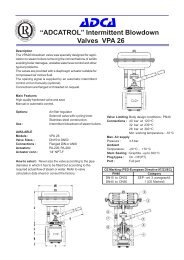
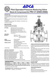
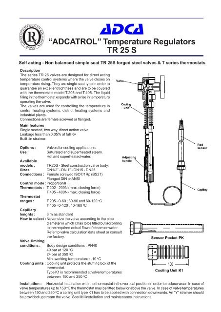
“<strong>ADCA</strong>TROL” Temperature Regulators<br />
TR 25 S<br />
Self acting - Non balanced simple seat TR 25S forged steel valves & T series thermostats<br />
Description<br />
The series TR 25 valves are designed for direct acting<br />
temperature control systems where the valve closes on<br />
temperature rising. They are single seat type in order to<br />
guarantee an excellent tightness and are to be coupled<br />
with the thermostats model T.205 and T.405. The liquid<br />
filling in the thermostat expands with a rise in tempersture<br />
operating the valve.<br />
The valves are used for controlling the temperature in<br />
central heating systems, district heating systems and<br />
industrial plants.<br />
Connections are female screwed or flanged.<br />
Main features<br />
Single seated, two way, direct action valve.<br />
Leakage less than 0.05% of full Kv<br />
Built -in strainer.<br />
Options :<br />
Use :<br />
Valves for cooling applications.<br />
Saturated and superheated steam.<br />
Hot and superheated water.<br />
Available<br />
models : TR25S - Steel construction valve body.<br />
Sizes : DN1/2” - DN 1” - DN15 - DN25<br />
Connections : Female screwed ISO7/1Rp (BS21)<br />
Flanged DIN or ANSI<br />
Control mode :Proportional<br />
Thermostats :<br />
Thermostat<br />
ranges :<br />
T.202 - 200N (max. closing force)<br />
T.405 - 400N (max. closing force)<br />
T.205 - 0-60 ; 30-90 and 60-120 o C<br />
T.405 - 0-120 ; 40-160 o C<br />
Capillary<br />
lenghts : 3 m as standard<br />
How to select : Never size the valve according to the pipe<br />
diameter in which it has to be fitted but according<br />
to the required actual flow of steam or water.<br />
Refer to valve calculation data sheet or consult<br />
the factory.<br />
Valve limiting<br />
conditions :<br />
Body design conditions : PN40<br />
40 bar at 120 o C<br />
24 bar at 350 o C<br />
Min. working temperature : -10 o C<br />
Cooling units : Cooling unit protects the stuffing box of the<br />
thermostat.<br />
Type K1 is recommended at valve temperatures<br />
between 150 and 250 o C<br />
Installation : Horizontal installation with the thermostat in the vertical position in order to reduce wear. In case of<br />
valve temperatures up to 150 o C the thermostat may be fitted below or above the valve. In case of valve temperatures<br />
between 150 and 250 o C a colling unit type K1 has to be applied with connection downwards. An “Y” strainer should<br />
be provided upstream the valve. See IMI installation and maintenance instructions.
Dimensions (mm)<br />
Type A B C E Kg<br />
T.205 305 405 210 22 1.8<br />
T.405 385 525 390 22 2.6<br />
Specifications<br />
Type Connection Opening DN Kvs value Valve Stroke<br />
DN in mm m3/h mm<br />
TR25-15/4 15 4 0.20 6<br />
TR25-15/6 15 6 0.45 6<br />
TR25-15/9 15 9 0.95 6<br />
TR25-15/12 15 12 1.70 6<br />
TR25-15 15 15 2.75 6<br />
TR25-20/9 20 9 0.95 6.5<br />
TR25-20/15 20 15 2.75 6.5<br />
TR25-20/20 20 20 5 6.5<br />
TR25-25/20 25 20 5 7<br />
Max. Permissible Diff.pressure<br />
with T 205 thermostat :<br />
21 bar for valve DN15 with 4 & 6 mm seat diam.<br />
13 bar for valve DN15 with 9 mm seat diam.<br />
9.3 bar for valve DN15 with 12 mm seat diam.<br />
5.3 bar for valve DN15<br />
5.3 bar for valve DN20 with 15 mm seat diam.<br />
2.9 bar for valve DN20 with 20 mm seat diam.<br />
2.9 bar for valve DN25 with 20 mm seat diam.<br />
With T.405 thermostat :<br />
40 bar for valve DN15 with 4 & 6 mm seat diam.<br />
38 bar for valve DN15 with 9 mm seat diam.<br />
24 bar for valve DN15 with 12 mm seat diam.<br />
15 bar for valve DN15<br />
15 bar for valve DN20 with 15 mm seat diam.<br />
9 bar for valve DN20 with 20 mm seat diam.<br />
9 bar for valve DN25 with 20 mm seat diam.<br />
Valve Dimensions (mm)<br />
Screwed ends DIN Flanges<br />
DN A B C F Kg D E Kg<br />
1/2” 90 40 70 50 1.2 130 47.5 2.6<br />
3/4” 90 40 70 50 1.2 150 52.5 3.2<br />
3/4”* 100 45 75 55 1.6 150 52.5 3.6<br />
1” 100 45 75 55 1.6 160 57.5 4.2<br />
* Only model TR25-20/20<br />
Materials (TR25)<br />
Pos. Designation Material<br />
1 Body C 22.8<br />
2 Bonnet AISI 304<br />
3* Gasket St.st. / Graphite<br />
4* Valve AISI 316<br />
5 Seat AISI 316<br />
6* Spring AISI 302<br />
7 Cap A 105<br />
8* Strainer screen AISI 304<br />
9* Cap gasket St. st. / Graphite<br />
* Available spare parts<br />
Proportional band<br />
The proportional band is the temperature change required for the valve to move from fully open to fully closed. It<br />
depends on the valve stroke and on the thermostat movement per o C, and is calculated as follows.<br />
Proportional Band = Valve stroke (mm)<br />
Thermostat mov. (mm/ o C)<br />
Thermostat movement in mm per o C<br />
A proportional band in the range 8-13 o C is suitable for most applications. A smaller proportional band is not ideal where<br />
heat load varies rapidly.