Series VQ/Base Mounted - SMC ETech
Series VQ/Base Mounted - SMC ETech
Series VQ/Base Mounted - SMC ETech
- No tags were found...

Create successful ePaper yourself
Turn your PDF publications into a flip-book with our unique Google optimized e-Paper software.
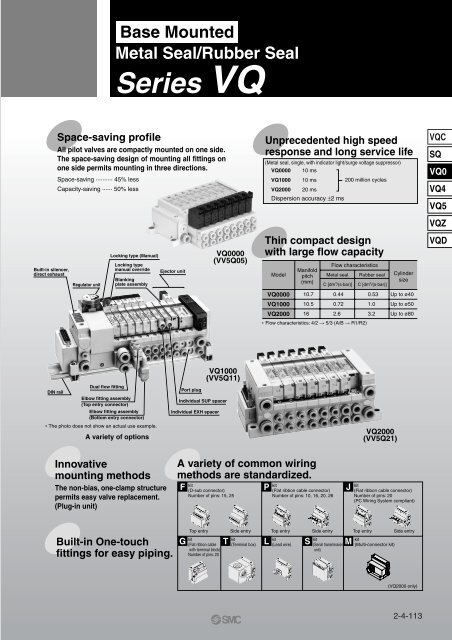
<strong>Base</strong> <strong>Mounted</strong>Metal Seal/Rubber Seal<strong>Series</strong> <strong>VQ</strong>Built-in silencer,direct exhaustSpace-saving profileAll pilot valves are compactly mounted on one side.The space-saving design of mounting all fittings onone side permits mounting in three directions.Space-saving ·········· 45% lessCapacity-saving ······ 50% lessRegulator unitLocking type (Manual)Locking typemanual overrideBlankingplate assemblyEjector unit<strong>VQ</strong>0000(VV5Q05)Unprecedented high speedresponse and long service life(Metal seal, single, with indicator light/surge voltage suppressor)<strong>VQ</strong>0000<strong>VQ</strong>1000<strong>VQ</strong>200010 ms10 ms20 ms200 million cyclesDispersion accuracy ±2 msThin compact designwith large flow capacityModel<strong>VQ</strong>0000<strong>VQ</strong>1000<strong>VQ</strong>2000Manifoldpitch(mm)10.710.516Flow characteristicsMetal seal Rubber seal CylindersizeC [dm 3 /(s·bar)] C [dm 3 /(s·bar)]0.440.722.6∗ Flow characteristics: 4/2 5/3 (A/B R1/R2)0.531.03.2Up to ø40Up to ø50Up to ø80<strong>VQ</strong>CSQ<strong>VQ</strong>0<strong>VQ</strong>4<strong>VQ</strong>5<strong>VQ</strong>Z<strong>VQ</strong>DDIN railDual flow fittingElbow fitting assembly(Top entry connector)Elbow fitting assembly(Bottom entry connector)∗ The photo does not show an actual use example.A variety of optionsPort plugIndividual EXH spacer<strong>VQ</strong>1000(VV5Q11)Individual SUP spacer<strong>VQ</strong>2000(VV5Q21)Innovativemounting methodsThe non-bias, one-clamp structurepermits easy valve replacement.(Plug-in unit)A variety of common wiringmethods are standardized.F P Jkit(D-sub connector)Number of pins: 15, 25kit(Flat ribbon cable connector)Number of pins: 10, 16, 20, 26kit(Flat ribbon cable connector)Number of pins: 20(PC Wiring System compliant)Built-in One-touchfittings for easy piping.Top entry Side entry Top entry Side entry Top entry Side entrykitkitkitkitkit(Flat ribbon cable (Terminal box) (Lead wire)(Serial transmission (Multi-connector kit)with terminal block)unit)Number of pins: 20G T L S M(<strong>VQ</strong>2000 only)2-4-113
Valve SpecificationsSonicconductanceC [dm 3 /(s·bar)]4/2 5/3(A/B R1/R2)DoubleSingle3 positionClosed centerSingleType of actuation Voltage Electrical entry Manual overrideDoubleClosed centerExhaust centerPressure center12 V100 V 200 V24 V110 V 220 VDC AC AC50/60 50/60Hz HzPlug-inGrommetL plug connectorM plug connectorPush type, Tool requiredLocking typeLocking type (Manual)Rubber seal<strong>VQ</strong>00 0.720.72<strong>Series</strong><strong>VQ</strong>1000<strong>Base</strong> <strong>Mounted</strong>Plug lead Plug-inP. 2-4-120<strong>Series</strong><strong>VQ</strong>2000P. 2-4-124<strong>Series</strong><strong>VQ</strong>0000P. 2-4-182<strong>Series</strong><strong>VQ</strong>1000Rubber seal Metal seal Rubber seal Metal seal Rubber seal Metal seal<strong>VQ</strong>101<strong>VQ</strong>200<strong>VQ</strong>201<strong>VQ</strong>050<strong>VQ</strong>051<strong>VQ</strong>1101.02.63.20.440.530.720.652.02.20.320.440.72(F/L kit only)P. 2-4-128(F/L kit only)P. 2-4-128P. 2-4-186Metal seal<strong>VQ</strong>1111.00.65P. 2-4-184P. 2-4-1862-4-114
P. 2-4-215P. 2-4-215For S kit, please contact <strong>SMC</strong>. For S kit, please contact <strong>SMC</strong>. For S, G kit, please contact <strong>SMC</strong>.For S, G kit, please contact <strong>SMC</strong>.Except L kitExcept L kitExcept L kitStandardP. 2-4-177P. 2-4-172P. 2-4-208P. 2-4-210P. 2-4-177 P. 2-4-166Except L kitExternal pilotD-sub connector 15PFlat ribbon cable 10P 16P 20PNegative common specificationsOne-touch fittingInch sizeFor special wiring spec.Blanking plateIndividual SUP/EXHSUP/EXH passage spacerName plateBack pressure check valveDIN rail mounting styleBuilt-in silencerSilencer for EXH portElbow fitting for cylinder portTwo stations matchingfittings for double flow ratePlug for cylinder portRegulator unitEjector unit mountedDouble check blockOptionManifold Option2-4-115<strong>VQ</strong>CSQ<strong>VQ</strong>0<strong>VQ</strong>4<strong>VQ</strong>5<strong>VQ</strong>Z<strong>VQ</strong>D
<strong>Series</strong> <strong>VQ</strong>/<strong>Base</strong> <strong>Mounted</strong>: VariationsManifold VariationsFPJGkitkitkitkitD-sub connectorConforming to MIL D-sub connector<strong>Series</strong><strong>VQ</strong>1000Flat ribbon cableconnector(26, 20, 16, 10 pins)Conforming to MIL flat ribboncable connectorFlat ribbon cableconnector(20 pins)Conforming to MIL flat ribboncable connectorPC Wiring System compatibleFlat ribbon cablewith power supplyterminal blockConforming to MIL flat ribbon cableconnectorApplicable to OMRON’s serial transmissionunitPC Wiring System compatiblePlug-in<strong>Series</strong><strong>VQ</strong>2000P. 2-4-130P/J kitP. 2-4-134 P. 2-4-142P. 2-4-130P/J kitP. 2-4-134 P. 2-4-142<strong>Series</strong><strong>VQ</strong>0000Plug Lead<strong>Series</strong><strong>VQ</strong>1000P. 2-4-188P kit onlyP. 2-4-192P. 2-4-188 P kit onlyP. 2-4-192P. XXX2-4-116
TkitManifold VariationsL CSkitkitMkitTerminal block box(Terminal block)Terminal blocks are compactlyarranged on one side.Lead wireDirect electrical entry typeSerial transmission unitEnables single-wire solenoidvalve-PLC operationCircular connectorIP65 (Dusttight/Low jetproof type)<strong>VQ</strong>CSQ<strong>VQ</strong>0Lkit<strong>VQ</strong>4<strong>VQ</strong>5<strong>VQ</strong>Z<strong>VQ</strong>DTerminal block boxP. 2-4-146P. 2-4-150 P. 2-4-154LkitEnclosureIP65 compliantEnclosureIP65 compliantEnclosureIP65 compliantP. 2-4-146 P. 2-4-150 P. 2-4-154W type onlyP. 2-4-158CkitTerminal blockP. 2-4-196 P. 2-4-200 P. 2-4-204CkitTerminal blockP. 2-4-196 P. 2-4-200 P. 2-4-2042-4-117
2-4-118
Cylinder Speed Chart<strong>Series</strong><strong>VQ</strong>0151Port size:One-touch fitting for ø4<strong>VQ</strong>1101Port size:One-touch fitting for ø6<strong>VQ</strong>2101Port size:One-touch fitting for ø8Bore size<strong>Series</strong> CJ2<strong>Series</strong> CM2<strong>Series</strong> MB, CA1Average Pressure 0.5 MPa Pressure 0.5 MPaPressure 0.5 MPaspeed Load factor 50% Load factor 50%Load factor 50%(mm/s) Stroke 60 mmStroke 300 mmStroke 500 mmø6 ø10 ø16 ø20 ø25 ø32 ø40 ø40 ø50 ø63 ø80 ø100800700Perpendicular,600upward actuation500400Horizontal300actuation200100080070060050040030020010008007006005004003002001000Use as a guide for selection.Please confirm the actual conditions with<strong>SMC</strong> Sizing Program.<strong>VQ</strong>CSQ<strong>VQ</strong>0<strong>VQ</strong>4<strong>VQ</strong>5<strong>VQ</strong>Z<strong>VQ</strong>D∗ It is when the cylinder is extending that is meter-out controlled by speed controller which is directly connected with cylinder, and its needle valvewith being fully open.∗ The average velocity of the cylinder is what the stroke is divided by the total stroke time.∗ Load factor: ((Load weight x 9.8)/Theoretical force) x 100%Conditions<strong>Series</strong><strong>VQ</strong>0151<strong>VQ</strong>1101<strong>VQ</strong>2101ConditionsTube bore x LengthSpeed controllerSilencerTube bore x LengthSpeed controllerSilencerTube bore x LengthSpeed controllerSilencer<strong>Series</strong> CJ2 <strong>Series</strong> CM2 <strong>Series</strong> MB, CA1T0425 x 1 mAS2001F-04AN103-X233T0604 x 1 mAS3001F-06AN103-X233T0806 x 1 mAS3001F-08AN200-KM82-4-119
<strong>Series</strong> <strong>VQ</strong>1000<strong>Base</strong> <strong>Mounted</strong>Plug-in UnitFor details about certified productsconforming to international standards,visit us at www.smcworld.com.VV5Q 1 1 08 C6<strong>Series</strong>1 <strong>VQ</strong>1000Manifold1Plug-in unitStations01···1 station···The maximum and minimumnumber of stations arevaried depending on kit.(Refer to the table below.)How to Order ManifoldCylinder portSymbol Port size Symbol Port sizeC3C4C6M5CML3L4With One-touch fitting for ø3.2With One-touch fitting for ø4With One-touch fitting for ø6M5 threadWith mixed size/with port plug (1)W/ elbow One-touch fitting ø3.2 for top pipingW/ elbow One-touch fitting ø4 for top pipingL6L5B3B4B6B5LMW/ elbow One-touch fitting ø6 for top pipingElbow M5 thread for top pipingW/ elbow One-touch fitting ø3.2 for bottom pipingW/ elbow One-touch fitting ø4 for bottom pipingW/ elbow One-touch fitting ø6 for bottom pipingElbow M5 thread for bottom pipingMixed size for elbow pipingNote 1) Specify “Mixed size/with port plug” in the manifold specification sheet.Note 2) Inch-size One-touch fittings are also available. For details, refer to page 2-4-179.Note 3) M5 fittings for M5 thread are attached without being incorporated.FU1OptionSymbolOptionNilNone2 200/220 VAC models (Applicable to F and L kits)BWith back pressure check valve (2)DDIN rail mountingG11 set of regulator unit (3)G22 sets of regulator unit (3)G33 sets of regulator unit (3)JWith vacuum ejector unit (4)K Special wiring specifications (Not double wiring) (5)NWith name plateRExternal pilot (6)SBuilt-in silencer, direct exhaustNote 1) When two or more symbols are specified, indicatethem alphabetically. Example) -BRSNote 2) Models with a suffix “-B“ have check valves forprevention of back pressure at all manifoldstations. If not all stations need this check valve,specify the stations where check valves areinstalled by using the manifold specification sheet.Note 3) Specify the mounting position in the manifoldspecification sheet.Note 4) Refer to page 2-4-170 for the details of ejectormounted styles. A combination of “J“ and “N“ isunavailable.Note 5) Specify the wiring by means of the manifoldspecification sheet. (Except L kit)Note 6) Indicate “R“ for the valve with external pilot.Simple specials are available with <strong>SMC</strong> Simple Specials System.For details about applicable models, please contact <strong>SMC</strong>.Kit/Electrical entry/Cable lengthFConnector entry directionTop entry Side entryKitFU0U1U2U3kit(D-sub connector)kit(Flat ribbon cablekitconnector)connector (20P))Top entry Top entry Top entryKitFS0S1S2S3Without cableWith cable (1.5 m)With cable (3 m)With cable (5 m)(2)2 to 24stationsKitP J G25PNote 1) 26PNote 1) Note 1)26PSide entry Side entry Side entryConnector entry directionTop entry Side entryU0S0KitPU1U2U3KitPS1S2S3Without cableWith cable (1.5 m)With cable (3 m)With cable (5 m)2 to 24stationsConnector entry directionTop entry Side entryU0S0(2)Kit U1Kit S1J U2U3J S2S3Without cableWith cable (1.5 m)With cable (3 m)With cable (5 m)2 to 16stationsNote 1) Besides the above, F and P kits with different number of pins are available. Refer to page 2-4-177 for details.Note 2) For details, refer to page 2-4-178.(Flat ribbon cableconnector with powersupply terminal block)The valve is equipped withCompatible only with 24VDC valves.Order separatelySI unit made byOMRON Corp.P. 2-4-130 P. 2-4-134 P. 2-4-138 P. 2-4-142U0 Without cable(2) (2)Kit U1 With cable (1.5 m) 2 to 16G U2U3With cable (3 m)With cable (5 m)stations2-4-120
Plug-in Unit<strong>Base</strong> <strong>Mounted</strong><strong>Series</strong> <strong>VQ</strong>1000How to Order Valves<strong>VQ</strong> 1 1 0 0 Y 5<strong>Series</strong>1 <strong>VQ</strong>1000Type of actuation12345T2 position singleMetalRubber2 position double2 position double3 position closed center3 position exhaust center3 position pressure center4 position dual 3 port valveNote) (A) 4 2A5 3N.C 1 N.C4 position dual 3 port valveNote) (B) 4 2B5 3N.O 1 N.O4 position dual 3 port valveNote) (C) 4 2C5 3N.C 1 N.Okit(Terminal box)Seal01Metal sealRubber sealFunctionSymbol SpecificationsNil Standard typeHYHigh pressuretypeLow wattagetypeNote) For power consumptionof AC type, refer to page2-4-129.Note) For external pilot and negativeCOM specifications, refer to“Option” on pages 2-4-178 to 2-4-179.Note) Rubber seal type only.Lkit(Lead wire cable)Manual overrideNil: Non-locking B: Push-lockingpush type slotted type(Tool required)C: Locking typeLight/Surge(Manual)voltage suppressorNil YesNote)E NoneNote) Inapplicableto the S kit.Coil voltage1 100 VAC (50/60 Hz)DC ACNote)2 200 VAC (50/60 Hz)(1.0 W) Note) 3 110 VAC (50/60 Hz)Note)4 220 VAC (50/60 Hz)(1.5 W)—5 24 VDC6 12 VDC(0.5 W) —Note) 200/220 VACmodels areapplicable to Fand L kits.How to Order Manifold AssemblyExampleSingle solenoid (24 VDC)<strong>VQ</strong>1100-5 (4 sets)D-sub connectorF kit(D-sub connector)kitS (Serial transmission unit)D side U side1 2 3 ·········· StationsDouble solenoid (24 VDC)<strong>VQ</strong>1200-5 (4 sets)Blanking plate<strong>VQ</strong>1000-10A-1 (1 set)Cylinder portsC6: With One-touch fitting for ø6Manifold base (9 stations)VV5Q11-09C6FU2VV5Q11-09C6FU2 ···· 1 set (F kit 9 station manifold base no.)∗<strong>VQ</strong>1100-5 ·········· 4 sets (Single solenoid part no.)∗<strong>VQ</strong>1200-5 ·········· 4 sets (Double solenoid part no.)∗VV1000-10A-1 ······ 1 set (Blanking plate part no.)The asterisk denotes the symbol for assembly.Prefix it to the part nos. of the solenoid valve, etc.Specify the part numbers for valves and options togetherbeneath the manifold base part number. Besides, when thearrangement will be complicated, specify them by means ofthe manifold specification sheet.The valve is equipped with anindicator light and surge voltagesuppressor, and the voltage is 24VDC. The dust proof SI unit is alsoavailable. Refer to page 2-4-154 fordetails.P. 2-4-154<strong>VQ</strong>CSQ<strong>VQ</strong>0<strong>VQ</strong>4<strong>VQ</strong>5<strong>VQ</strong>Z<strong>VQ</strong>DP. 2-4-146Kit T O Terminal block box 2 to 24 stations (2)KitL012With cable (0.6 m)With cable (1.5 m)With cable (3 m)P. 2-4-1501 to 8stationsKitS0AMitsubishi Electric Corp.:BMELSECNET/MINI-S3 Data Link SystemC OMRON Corp.: SYSBUS Wire SystemD SHARP Corp.: Satellite I/O Link SystemE Matsushita Electric Works: MEWNET-F SystemF1 NKE Corp.: Uni-wire System (16 output points)G Rockwell Automation: Allen Bradley Remote I/O (RIO) SystemH NKE Corp.: Uni-wire H SystemJ1 SUNX Corp.: S-LINK System (16 output points)J2 SUNX Corp.: S-LINK System (8 output points)K Fuji Electric Co.: T-LINK Mini SystemQ DeviceNet, CompoBus/D (OMRON Corp.)R1 OMRON Corp.: CompoBus/S System (16 output points)R2VWithout SI unitWith general type SI unit (<strong>Series</strong> EX300)OMRON Corp.: CompoBus/S System (8 output points)Mitsubishi Electric Corp.: CC-LINK System(2)Max.16stationsMax. 8 stationsMax.16stationsMax. 8 stationsMax. 16 stations2-4-121
<strong>Base</strong> <strong>Mounted</strong><strong>Series</strong> <strong>VQ</strong>1000Manifold OptionP. 2-4-208Blanking plate assemblyV<strong>VQ</strong>1000-10A-1SUP block plateV<strong>VQ</strong>1000-16ADouble check block<strong>VQ</strong>1000-FPG-2 stations matching fitting assemblyV<strong>VQ</strong>1000-52A-C8Blanking plug2304KQ2P- 0608ToCYL portIndividual SUP spacerV<strong>VQ</strong>1000-P-1-C6EXH block base assemblyF C3V<strong>VQ</strong>1000-19A- P C4-LC6M5Elbow fitting assemblyV<strong>VQ</strong>1000-F-LC3C4C6M5Silencer (For EXH port)AN200-KM8/AN203-KM8Blanking plate with connectorV<strong>VQ</strong>1000-1C-C6 (SUP port)One-touch fitting for ø6Connector assemblyIndividual EXH spacerV<strong>VQ</strong>1000-R-1-C6C6 (EXH port)One-touch fitting for ø6Back pressure check valve assembly [-B] DIN rail mounting bracket [-D]V<strong>VQ</strong>1000-18AV<strong>VQ</strong>1000-57ARegulator unitV<strong>VQ</strong>1000-AR-1• For cylinder port fittingspart no., refer to page 2-4-175.• For replacement parts,refer to page 2-4-227.With vacuum ejector unit[-J]Name plate [-N]Built-in silencer,V<strong>VQ</strong>1000-NNC-Station (1 to Max. stations) direct exhaust [-S]Exhaust portPort plugV<strong>VQ</strong>0000-58A2-4-122
2-4-123
01···2Stations1 station···VV5Q 2 1<strong>Series</strong><strong>VQ</strong>2000The maximum andminimum number ofstations are varieddepending on kit.(Refer to the tablebelow.)<strong>Series</strong> <strong>VQ</strong>2000<strong>Base</strong> <strong>Mounted</strong>Plug-in Unit1ManifoldPlug-in unit08 C6Cylinder portHow to Order ManifoldFU1Kit typeSymbol Port size Symbol Port sizeC4C6C8CML4L6With One-touch fitting for ø4With One-touch fitting for ø6With One-touch fitting for ø8With mixed size/with port plug (1)W/ elbow One-touch fitting ø4 for top pipingW/ elbow One-touch fitting ø4 for top pipingL8B4B6B8LMW/ elbow One-touch fitting ø8 for top pipingW/ elbow One-touch fitting ø4 for bottom pipingW/ elbow One-touch fitting ø6 for bottom pipingW/ elbow One-touch fitting ø8 for bottom pipingMixed size for elbow pipingNote 1) Specify “Mixed size/with port plug” on the manifold specificationsheet.Note 2) Inch-size One-touch fittings are available. For details, refer to page2-4-179.Simple specials are available with <strong>SMC</strong> Simple Specials System.For details about applicable models, Contact <strong>SMC</strong>.OptionFor details about certified productsconforming to international standards,visit us at www.smcworld.com.SymbolOptionNilBDKNRSWNoneBack pressure check valve (2)DIN rail mounting styleSpecial wiring specifications (Except double wiring) (3)With name plateExternal pilot (4)Built-in silencer, direct exhaustEnclosure: Dust tight/splashproof type(IP65) [T, L, S and M kits only]Note 1) When two or more symbols arespecified, indicate themalphabetically. Example) -DNR.Note 2) Models with a suffix “-B” have checkvalves for prevention of back pressureat all manifold stations. If not allstations need this check valve, specifythe stations where check valves areinstalled by manifold specificationsheet.Note 3) Specify the wiring specifications inthe manifold specification sheet.(Except L kit)Note 4) Indicate “R” for the valve withexternal pilot.Kit/Electrical entry/Cable lengthFkit(D-sub connector)Side entrykitP J Gkit(Flat ribbon cableconnector)kit(Flat ribbon cableconnector (20P))Side entry(Flat ribbon cableconnector with powersupply terminal block)Compatible onlywith 24 VDC valves.Note 1)25PTop entryNote 1)26PTop entryNote 1)26PTop entryConnector entry directionTop entry Side entryKitFU0U1U2U3KitFS0S1S2S3P. 2-4-130Connector entry directionConnector entry directionP. 2-4-134Top entry Side entryTop entry Side entryP. 2-4-138 P. 2-4-142Without cableU0S0Without cableU0S0Without cableU0 Without cable(2) (2) (2) (2)With cable (1.5 m) 2 to 24 Kit U1Kit S1With cable (1.5 m) 2 to24 Kit U1Kit S1With cable (1.5 m) 2 to16 Kit U1 With cable (1.5 m) 2 to 16With cable (3 m) stationsWith cable (5 m)P U2U3P S2S3With cable (3 m)With cable (5 m)stations J U2U3J S2S3With cable (3 m)With cable (5 m)stations G U2U3With cable (3 m)With cable (5 m)stations2-4-124
Plug-in Unit<strong>Base</strong> <strong>Mounted</strong><strong>Series</strong> <strong>VQ</strong>2000How to Order Valves<strong>VQ</strong> 2 1 0 0 Y 5<strong>Series</strong>2 <strong>VQ</strong>2000Type of actuation2 position single12345MetalRubber2 position double2 position double3 position closed center3 position exhaust center3 position pressure center4 position dual 3 port valveNote) (A) 4 2A5N.C 13N.C4 position dual 3 port valve(B) 4 2Note)B5 3N.O 1 N.O4 position dual 3 port valveNote) (C)4 2CSeal5 3N.C 1 N.ONote) Rubber sealtype only.0 Metal seal1 Rubber sealNote ) For sub-plate singleunit type, refer to page2-4-165.Light/Surgevoltage suppressorNil YesNote)E NoneNote) Inapplicableto the S kit.EnclosureNil Dust-protectedW Dusttight/Low jetproof type (IP65)Manual overrideNil: Non-locking B: Push-lockingpush type slotted type(tool required)Coil voltageFunctionSymbol Specifications DC AC1Note)2100 VAC (50/60 Hz)200 VAC (50/60 Hz)NilHNote)Standard (1.0 W) 3 110 VAC (50/60 Hz)type Note)4 220 VAC (50/60 Hz)High (1.5 W) 5 24 VDC—pressure type 6 12 VDCLow wattage (0.5 W)Note) 200/220 VACY—typemodels areapplicable to FNote) For power consumptionand L kits.of AC type, refer topage 2-4-129.Note) For external pilot and negative COM specifications,refer to “Option” on page 2-4-178 to 2-4-179.C:Locking type(Manual)How to Order Manifold AssemblyExampleDouble solenoid (24 VDC)<strong>VQ</strong>2200-5 (4 sets)Single solenoid (24 VDC)<strong>VQ</strong>2100-5 (3 sets)D side U side1 2 3 ······· StationsBlanking plate<strong>VQ</strong>2000-10A-1 (1 set)D-sub connectorAXT100-DS25-030F kitCylinder ports(D-sub connector)C8: With One-touchfitting for ø8Manifold base (8 stations)VV5Q21-08C8FU2VV5Q21-08C8FU2 ··· 1 set (F kit 8 station manifold base no.)∗<strong>VQ</strong>2100-5 ········· 3 sets (Single solenoid part no.)∗<strong>VQ</strong>2200-5 ········· 4 sets (Double solenoid part no.)∗V<strong>VQ</strong>2000-10A-1 ·· 1 set (Blanking plate part no.)The asterisk denotes the symbol for assembly.Prefix it to the part nos. of the solenoid valve, etc.Specify the part numbers for valves and options togetherbeneath the manifold base part number. Besides, when thearrangement will be complicated, specify them by means ofthe manifold specification sheet.<strong>VQ</strong>CSQ<strong>VQ</strong>0<strong>VQ</strong>4<strong>VQ</strong>5<strong>VQ</strong>Z<strong>VQ</strong>DTKit Tkit(Terminal box)Dust tight/Low jetproof type(IP65) availableOTerminalblock boxP. 2-4-1462 to 20stations (2)Lkit(Lead wire cable)Dust tight/Low jetproof type(IP65) availableKitL012P. 2-4-150With cable (0.6 m)1 to 8With cable (1.5 m)stationsWith cable (3 m)kitkitS M (Serial transmission unit)(4)(Multi-connector)The valve is equipped with an indicator light andsurge voltage suppressor, and the voltage is 24VDC. The dusttight SI unit is available. Refer topage 2-4-154 for details. Dusttight/splashprooftype (IP65) is also available. (Except SE and SG.)Note 1) Besides the above, F and P kits with different number of pins are available. Refer to page 2-4-177 for details.Note 2) For details, refer to page 2-4-178.Note 3) Refer to the pages on respective kits for IP65 type. (T, L and S kits)Note 4) Kits with IP65 enclosure applicable to input/output are also available. Refer to page 2-4-162 for details.KitSOAB(4)Mitsubishi Electric Corp.:BBMELSECNET/MINI-S3 Data Link System(2 power supply lines)CDEF1GHJ1J2KQR1R2VP. 2-4-154Without SI unitWith general type SI unit (<strong>Series</strong> EX300)Mitsubishi Electric Corp.:MELSECNET/MINI-S3 Data Link SystemOMRON Corp.: SYSBUS Wire SystemSHARP Corp.: Satellite I/O Link SystemMatsushita Electric Works: MEWNET-F SystemNKE Corp.: Uni-wire System (16 output points)Rockwell Automation: Allen Bradley Remote I/O (RIO) SystemNKE Corp.: Uni-wire H SystemSUNX Corp.: S-LINK System (16 output points)SUNX Corp.: S-LINK System (8 output points)Fuji Electric Co.: T-LINK Mini SystemDeviceNet, CompoBus/D (OMRON Corp.)OMRON Corp.: CompoBus/S System (16 output points)OMRON Corp.: CompoBus/S System (8 output points)Mitsubishi Electric Corp.: CC-LINK System(2)Max.16stationsDust tight/Low jetproof typeMax.16 stations(IP65) only available(2)Max.16stationsMax. 8 stationsMax.16stationsKitMax. 8 stations MMax. 16 stations0123P. 2-4-162Without cableWith cable (1.5 m)With cable (3 m)With cable (5 m)(2)2 to 24stations2-4-125
<strong>Base</strong> <strong>Mounted</strong><strong>Series</strong> <strong>VQ</strong>2000Manifold OptionP. 2-4-210Blanking plate assemblyV<strong>VQ</strong>2000-10A-1SUP block plateV<strong>VQ</strong>2000-16ADIN rail mounting bracket [-D]V<strong>VQ</strong>2000-57APort plugV<strong>VQ</strong>1000-58AIndividual SUP spacerV<strong>VQ</strong>2000-P-1-C8EXH block plateV<strong>VQ</strong>2000-19ABuilt-in silencer,direct exhaust [-S]Blanking plug0406KQ2P-0810C8 (SUP port)One-touch fitting for ø8Exhaust portIndividual EXH spacerV<strong>VQ</strong>2000-R-1-C8C8 (EXH port)One-touch fitting for ø8Name plate [-N]V<strong>VQ</strong>2000-N-Station (1 to Max. stations)Silencer (For EXH port)AN200-KM10• For cylinder port fittings partno., refer to page 2-4-175.• For replacement parts, refer topage 2-4-227.Back pressure check valve assembly [-B]V<strong>VQ</strong>2000-18AElbow fitting assemblyV<strong>VQ</strong>2000-F-L (C4, C6, C8)2 stations matching fitting assemblyV<strong>VQ</strong>2000-52A-C10Double check block<strong>VQ</strong>2000-FPG-ToCYL port2-4-126
<strong>VQ</strong>CSQ<strong>VQ</strong>0<strong>VQ</strong>4<strong>VQ</strong>5<strong>VQ</strong>Z<strong>VQ</strong>D2-4-127
<strong>Series</strong> <strong>VQ</strong>1000/2000<strong>Base</strong> <strong>Mounted</strong>Plug-in UnitModel<strong>Series</strong><strong>VQ</strong>1000<strong>VQ</strong>20002-4-1282 position3 position4 position2 position4 position 3 positionNumber ofsolenoidsSingleDoubleClosedcenterExhaustcenterPressurecenterDual3 port valveSingleDoubleClosedcenterExhaustcenterPressurecenterDual3 port valveModelMetal sealRubber sealMetal sealRubber sealMetal sealRubber sealMetal sealRubber sealMetal sealRubber sealRubber sealMetal sealRubber sealMetal sealRubber sealMetal sealRubber sealMetal sealRubber sealMetal sealRubber sealRubber seal<strong>VQ</strong>1100<strong>VQ</strong>1101<strong>VQ</strong>1200<strong>VQ</strong>1201<strong>VQ</strong>1300<strong>VQ</strong>1301<strong>VQ</strong>1400<strong>VQ</strong>1401<strong>VQ</strong>1500<strong>VQ</strong>1501A<strong>VQ</strong>1 B01C<strong>VQ</strong>2100<strong>VQ</strong>2101<strong>VQ</strong>2200<strong>VQ</strong>2201<strong>VQ</strong>2300<strong>VQ</strong>2301<strong>VQ</strong>2400<strong>VQ</strong>2401<strong>VQ</strong>2500<strong>VQ</strong>2501A<strong>VQ</strong>2 B01CFlow characteristics (1)Response time (ms) (2)1 2/4 (P A/B) 2/4 3/5 (A/B R1/R2) Standard: 1 W Low wattage:C [dm 3 /(s·bar)] b Cv C [dm 3 /(s·bar)] b Cv H: 1.5 W 0.5 WAC0.70 0.15 0.16 0.72 0.25 0.18 12 or less 15 or less 29 or less0.85 0.20 0.21 1.0 0.30 0.25 15 or less 20 or less 34 or less0.70 0.15 0.16 0.72 0.25 0.18 10 or less 13 or less 13 or less0.85 0.20 0.21 1.0 0.30 0.25 15 or less 20 or less 20 or less0.68 0.15 0.16 0.72 0.25 0.18 20 or less 26 or less 40 or less0.70 0.20 0.16 0.65 0.42 0.18 25 or less 33 or less 47 or less0.68 0.15 0.16 0.72 0.25 0.18 20 or less 26 or less 40 or less0.70 0.20 0.16 1.0 0.30 0.25 25 or less 33 or less 47 or less0.70 0.15 0.16 0.72 0.25 0.18 20 or less 26 or less 40 or less0.85 0.20 0.21 0.65 0.42 0.18 25 or less 33 or less 47 or less0.702.02.22.02.22.02.02.02.02.43.21.80.200.150.280.150.280.150.280.150.280.170.280.280.160.460.550.460.550.460.490.460.490.570.800.460.702.63.22.63.22.02.22.63.22.02.21.80.200.150.300.150.300.180.310.150.300.180.310.280.160.600.800.600.800.460.600.600.800.460.600.4625 or less22 or less24 or less15 or less20 or less29 or less34 or less29 or less34 or less29 or less34 or less34 or lessNote 1) Cylinder port size C6: (<strong>VQ</strong>1000), C8: (<strong>VQ</strong>2000) without check valve option for prevention of back pressure.Note 2) As per JIS B 8375-1981 (Supply pressure; 0.5 MPa; with indicator light/surge voltage suppressor; clean air)The response time is subject to the pressure and quality of the air. The values at the time of ON are given for double types.33 or less29 or less31 or less20 or less26 or less38 or less44 or less38 or less44 or less38 or less44 or less44 or less47 or less49or less51or less20 or less26 or less58 or less64 or less58 or less64 or less58 or less64 or less64 or lessWeight(g)647890110
Plug-in Unit<strong>Base</strong> <strong>Mounted</strong><strong>Series</strong> <strong>VQ</strong>1000/2000MetalRubber2 position double2 position double3 position closed center3 position exhaust center3 position pressure centerManifold Specifications<strong>Series</strong><strong>VQ</strong>1000JIS Symbol2 position single<strong>Base</strong> modelVV5Q11-Type of connectionStandard SpecificationsSolenoid Valve specificationsNote 1)Note 2)Note 3)Note 4)Note 5) F kit–D-sub connector P kit–Flat ribbon cable connector J kit–Flat ribbon cable connector (20P) G kit– Flat ribbon cable connectorwith terminal block T kit–Terminal box L kit–Lead wire cable S kit–Serial transmission unitValve constructionFluidMaximum operating pressureMinimumoperating pressureSingleDouble3 positionAmbient and fluid temperatureLubricationManual override(2)Impact/Vibration resistanceEnclosureCoil rated voltageAllowable voltage fluctuationCoil insulation typePowerconsumption(Current)Port locationSide24 VDC12 VDC100 VAC110 VAC200 VAC220 VACPorting specifications(1)Port size1(P), 3(R) 4(A), 2(B)C8 (ø8)OptionBuilt-insilencer,direct exhaustMetal sealRubber sealAir/Inert gasAir/Inert gas0.7 MPa (High pressure type: 0.8 MPa)0.1 MPa0.15 MPa0.1 MPa0.1 MPa0.1 MPa0.2 MPa–10 to 50°C (1)F, P, T kits2 to 24 stationsJ, G, S kit2 to 16 stationsL kit1 to 8 stationsNot requiredPush type/Locking type (Tool required, Manual type) Option150/30 m/s 2Dust-protected, Dust tight/Low jetproof type (IP65) (5)12 , 24 VDC, 100, 110, 200, 220 VAC (50/60 Hz)±10% of rated voltageClass B or equivalent1 W DC (42 mA), 1.5 W DC (63 mA) (3) , 0.5 W DC (21 mA) (4)1 W DC (83 mA), 1.5 W DC (125 mA) (3) , 0.5 W DC (42 mA) (4)Inrush 1.2 VA (12 mA), Holding 1.2 VA (12 mA)Inrush 1.3 VA (12 mA), Holding 1.3 VA (12 mA)Inrush 2.4 VA (12 mA), Holding 2.4 VA (12 mA)Inrush 2.6 VA (12 mA), Holding 2.6 VA (12 mA)Use dry air to prevent condensation when operating at low temperatures.Impact resistance ··· No malfunction occurred when it is tested with a drop tester in the axial directionand at the right angles to the main valve and armature in both energized and deenergizedstates every once for each condition. (Values at the initial period)Vibration resistance ··· No malfunction occurred in a one-sweep test between 45 and 2000 Hz. Test wasperformed at both energized and de-energized states in the axial direction and atthe right angles to the main valve and armature. (Values at the initial period)Value for high voltage type (1.5 W)Value for low voltage type (0.5 W)Dusttight/Low jetproof type (IP65) is available on T, L, S and M kits of <strong>VQ</strong>2000.C3 (ø3.2)C4(ø4)C6 (ø6)M5 (M5 thread)(2)ApplicablestationsApplicablesolenoid valve<strong>VQ</strong>100<strong>VQ</strong>1015 stationweight(g)628(Single)759(Double,3 position)<strong>VQ</strong>CSQ<strong>VQ</strong>0<strong>VQ</strong>4<strong>VQ</strong>5<strong>VQ</strong>Z<strong>VQ</strong>D<strong>VQ</strong>2000VV5Q21-Note 1)Note 2) F kit–D-sub connector P kit–Flat ribbon cable connector J kit–Flat ribbon cable connector (20P) G kit– Flat ribbon cable connectorwith terminal block T kit–Terminal box L kit–Lead wire cable S kit–Serial transmission unit M kit–Multi-connectorSideInch-size One-touch fittings are also available. For details, refer to page 2-4-179.For details, refer to page 2-4-178.C10 (ø10)OptionBuilt-insilencer,direct exhaustC4 (ø4)C6 (ø6)C8 (ø8)F, P kits2 to 24 stationsJ, G, S kit2 to 16 stationsL kit1 to 8 stationsT kit2 to 20 stations<strong>VQ</strong>200<strong>VQ</strong>2011051(Single)1144(Double,3 position)R portR portType of connectionA, B portP portA, B portP portType of connection2-4-129
F<strong>VQ</strong>1000/2000Kit (D-sub connector) The D-sub connector reduces installation labor for electricalconnections. Using the D-sub connector (25P), (15P as an option) conforming toMIL standard permits the use of connectors put on the market andgives a wide interchangeability. Top or side receptacle position can be selected in accordance withthe available mounting space. Maximum stations are 24.D-sub Connector (25 pins)VV5Q11VV5Q21Manifold SpecificationsPorting specifications<strong>Series</strong> Port Port sizelocaition 1(P), 3(R) 4(A), 2(B)<strong>VQ</strong>1000 Side C8<strong>VQ</strong>2000 Side C10C3, C4, C6, M5C4, C6, C8ApplicablestationsMax. 24 stationsMax. 24 stationsAXT100-DS25- 015030050The D-sub connector cable assembly can be ordered individually orincluded in a specific manifold model no. Refer to How to Order Manifold.L4481655 2-M2.6 x 0.45Socket side14 251 1347.04Multi-core vinyl cable0.3 mm 2 x 25C~= ø10Terminal no.D-sub Connector Cable Assembly (Option)Cablelength (L)1.5 m3 m5 mNote) Types with 15 pin are also available. Refer to page 2-4-177 for details.Assembly part no.AXT100-DS25-015AXT100-DS25-030AXT100-DS25-050NoteCable 25 corex 24AWG∗ For other commercial connectors, use a 25 pins typewith female connector conforming to MIL-C-24308.Connector manufacturers’ example• Fujitsu Limited• Japan Aviation Electronics Industry, Ltd.• J.S.T. Mfg. Co., Ltd.• Hirose Electric Co., Ltd.ElectricCharacteristicsItem CharacteristicsConductor 65 orresistanceΩ/km, 20°C lessVoltage limitV, 1 min, AC1000InsulationresistanceMΩkm, 20°C5 ormoreNote) The min. bendingradius of D-subcable assembly is20 mm.Wire Color by Terminal No. ofD-sub Connector Cable AssemblyTerminal no. Lead wire color Dot marking12345678910111213141516171819202122232425Cable Assembly BlackBrownRedOrangeYellowPinkBluePurpleGrayWhiteWhiteYellowOrangeYellowPinkBluePurpleGrayOrangeRedBrownPinkGrayBlackWhiteNoneNoneNoneNoneNoneNoneNoneWhiteBlackBlackRedRedRedBlackBlackWhiteNoneNoneBlackWhiteWhiteRedRedWhiteNoneHow to Order Manifold121VV5Q 1 1 08 C6 U 1 N<strong>Series</strong><strong>VQ</strong>1000<strong>VQ</strong>2000ManifoldPlug-in unit02···24Stations2 stations···24 stationsNote) For details,refer to page2-4-178.Connector entrydirectionSymbolC3C4C6C8M5CMFUSTop entrySide entryCylinder portCable (Length)0123Without cableWith cable (1.5 m)With cable (3 m)With cable (5 m)Port sizeWith One-touch fitting for ø3.2With One-touch fitting for ø4With One-touch fitting for ø6With One-touch fitting for ø8M5 threadWith mixed size/with port plug<strong>VQ</strong>1000<strong>VQ</strong>2000(3)Note 1) Insert “L” (top piping) or “B” (bottompiping) for elbow type. Example) B6(Elbow One-touch fittings for ø6,bottom piping.)Note 2) Indicate “LM” for models with elbowfittings and mixed cylinder port sizes.Note 3) Specify “Mixed size/with port plug” inthe manifold specification sheet.Note 4) Inch-size One-touch fittings areavailable. For details, refer to page 2-4-179.OptionOption<strong>VQ</strong>1000 <strong>VQ</strong>2000 NoteNilNone B With back pressure check valve (2)D DIN rail mounting style G1 1 set of regulator unitG2 2 sets of regulator unit (3)G3 3 sets of regulator unitJ With vacuum ejector unit (4)KSpecial wiring specifications(Not double wiring) (5)N With name plate R External pilot (6)S Built-in silencer, direct exhaust Note 1) When two or more symbols are specified,indicate them alphabetically. Example) -BRSNote 2) Models with a suffix “-B” have checkvalves for prevention of back pressure atall manifold stations. If not all stationsneed this check valve, specify the stationswhere check valves are installed by usingthe manifold specification sheet.Note 3) Specify the mounting position in themanifold specification sheet.Note 4) Refer to page 2-4-170 for the details ofejector mounted styles. A combination of“J” and “N” is unavailable.Note 5) Specify the wiring by using of themanifold specification sheet.Note 6) Indicate “R” for the valve with external pilot.Symbol2-4-130
Plug-in Unit<strong>Base</strong> <strong>Mounted</strong><strong>Series</strong> <strong>VQ</strong>1000/2000D side U side1 2 3 ······· StationsD side U side1 2 3 ············ StationsThe total number of stations is tabulatedstarting from station one on the D side.VV5Q11VV5Q21 Electrical wiring specificationsD-sub connectorConnectorterminal no.As the standard electrical wiringspecifications, double wiring(connected to SOL. A and SOL.B) is adopted for the internalwiring of each station for 12stations or less, regardless ofvalve and option types.Mixed single and double wiring isavailable as an option. For details,refer to page 2-4-178.Terminal no.Polarity1 station {2 stations {SOL.ASOL.BSOL.ASOL.B114215(–)(–)(–)(–)3 stations {SOL.A 3 (–)SOL.B 16 (–)4 stations { SOL.BSOL.A174(–)(–)SOL.A 5 (–)5 stations { SOL.B 18 (–)SOL.A 6 (–)6 stations { SOL.B 19 (–)7 stations {8 stations {SOL.ASOL.BSOL.ASOL.B720821(–)(–)(–)(–)9 stations {SOL.A 9 (–)SOL.B 22 (–)10 stations { SOL.BSOL.A2310(–)(–)SOL.A 11 (–)11 stations { SOL.B 24 (–)SOL.A 12 (–)12 stations { SOL.B 25 (–)COM. 13 (+)Positive commonspecificationsNote) When using the negative commonspecifications, use valves for negativecommon. (Refer to page 2-4-178.)For details, refer to “Option” on page 2-4-178.(+)(+)(+)(+)(+)(+)(+)(+)(+)(+)(+)(+)(+)(+)(+)(+)(+)(+)(+)(+)(+)(+)(+)(+)(–)D-sub connector assemblyAXT100-DS25-Negative commonspecificationsLead wire colorBlackYellowBrownPinkRedBlueOrangePurpleYellowGrayPinkOrangeBlueRedPurpleBrownGrayPinkWhiteGrayWhiteBlackYellowWhiteOrangeNote)015030 Wire color050Dot markingNoneBlackNoneBlackNoneWhiteNoneNoneNoneNoneNoneBlackNoneWhiteWhiteWhiteBlackRedBlackRedRedWhiteRedNoneRed<strong>VQ</strong>CSQ<strong>VQ</strong>0<strong>VQ</strong>4<strong>VQ</strong>5<strong>VQ</strong>Z<strong>VQ</strong>DHow to Order Valves12<strong>VQ</strong> 1 1 0 0 Y 5<strong>Series</strong><strong>VQ</strong>1000<strong>VQ</strong>2000Type of actuation123452 position single2 position double3 position closed center3 position exhaust center3 position pressure center01SealMetal sealRubber sealNote) For external pilot andnegative COMspecifications, refer to“Option” on pages 2-4-178 to 2-4-179.FunctionSymbol SpecificationsNilHStandardtypeHighpressure typeNilBCManual overrideNon-locking push type (Tool required)Locking type (Tool required)Locking type (Manual)Light/Surge voltage suppressorNilEDC(1.0 W)(1.5 W)(0.5 W)YesNoneAC—Note)Low wattageY—type Note) For power consumption ofAC type, refer to page 2-4-129.Coil voltage123456100 VAC (50/60 Hz)200 VAC (50/60 Hz)110 VAC (50/60 Hz)220 VAC (50/60 Hz)24 VDC12 VDCHow to Order Manifold AssemblySpecify the part numbers for valves and optionstogether beneath the manifold base part number.D-sub connector kit with cable (3 m)VV5Q11-09C6FU2 ···· 1 set –Manifold base no.*<strong>VQ</strong>1100-5 ············· 2 sets–Valve part no. (Stations 1 to 2)*<strong>VQ</strong>1200-5 ············· 4 sets–Valve part no. (Stations 3 to 6)*<strong>VQ</strong>1300-5 ············· 2 sets–Valve part no. (Stations 7 to 8)*V<strong>VQ</strong>1000-10A-1 ······ 1 set–Blanking plate part no. (Station 9)Prefix the asterisk tothe part nos. of thesolenoid valve, etc.D side U side1 2 3 ······ StationsWrite sequentially from the1st station on the D side.When part nos. writtencollectively arecomplicated, specified byusing the manifoldspecification sheet.2-4-131
F<strong>VQ</strong>1000<strong>VQ</strong>1000/2000Kit (D-sub connector)The broken lines indicate the DIN rail mounting style [-D] and the side entry connection [-FS].Applicable connector:D-sub connector(Conforming to MIL-C-24308)P = 10.5Indicator lightManualoverrideMounting hole for M4~ = 2D sideStations1 2 3 4 5 6 7 8nU side3(R) EXH portDIN rail clamp screw< >: AC< >: AC2n-C3, C4, C6, M5C3: One-touch fitting for ø3.2C4: One-touch fitting for ø4C6: One-touch fitting for ø6M5: M5 thread1(P) SUP portDimensionsFormula L1 = 10.5n + 44.5, L2 = 10.5n + 62.5 n: Station (Maximum 24 stastions)Ln 2 3 4 5 6 7 8 9 10 11 12 13 14 15 16 17 18 19 20 21 22 23 24L1 65.5 76 86.5 97 107.5 118 128.5 139 149.5 160 170.5 181 191.5 202 212.5 223 233.5 244 254.5 265 275.5 286 296.5L2 83.5 94 104.5 115 125.5 136 146.5 157 167.5 178 188.5 199 209.5 220 230.5 241 251.5 262 272.5 283 293.5 304 314.5(L3) 112.5 125 125 137.5 150 162.5 175 187.5 187.5 200 212.5 225 237.5 250 250 262.5 275 287.5 300 312.5 325 325 337.5(L4) 123 135.5 135.5 148 160.5 173 185.5 198 198 210.5 223 235.5 248 260.5 260.5 273 285.5 298 310.5 323 335.5 335.5 348Vacuum ejector unit style: Formula L1 = 10.5n + 28.7 + (Number of ejector units x 26.7)L2 = 10.5n + 46.3 + (Number of ejector units x 26.7)L4 is L2 plus about 30.2-4-132
Plug-in Unit<strong>Base</strong> <strong>Mounted</strong><strong>Series</strong> <strong>VQ</strong>1000/2000<strong>VQ</strong>2000The broken lines indicate the DIN rail mounting style [-D] and the side entry connection [-FS].<strong>VQ</strong>CApplicable connector: D-sub connector (25P)(Conforming to MIL-C-24308)SQ<strong>VQ</strong>0Indicator lightManualoverride<strong>VQ</strong>4<strong>VQ</strong>5<strong>VQ</strong>Z<strong>VQ</strong>D~ = 4Mounting hole for 4-M5D sideStations1 2 3 4 5 6 7 8nU side3(R) EXH portDIN rail clamp screw< >: AC2n-C4, C6, C8C3: One-touch fitting for ø3.2C4: One-touch fitting for ø4C6: One-touch fitting for ø6C8: One-touch fitting for ø8P = 161(P) SUP portDimensionsLL1L2(L3)(L4)n285105137.514831011214117137150 162.5160.5 1735133153187.5198614916971651858181201919721710213233112292491224526513261281200 212.5 225 250 262.5 275 300 312.5210.5 223 235.5 260.5 273 285.5 310.5 323Formula L1 = 16n + 53, L2 = 16n + 7314277297325335.515293313337.53481630932917325345183413611935737720373393350 375 387.5 400 412.5360.5 385.5 398 410.5 423n: Station (Maximum 24 stations)21389409437.544822405425450460.523421441462.547324437457487.54982-4-133
P <strong>VQ</strong>1000/2000Kit (Flat ribbon cable connector)VV5Q11VV5Q21 MIL flat ribbon cable connector reduces installation labor forelectrical connection. Using the connector for flat ribbon cable (26P) conforming to MILstandard permits the use of connectors put on the market andgives a wide interchangeability. Top or side receptacle position can be selected in accordance withthe available mounting space. Maximum stations are 24.Manifold Specifications<strong>Series</strong><strong>VQ</strong>1000<strong>VQ</strong>2000PortlocationSideSidePorting specificationsPort size1(P), 3(R) 4(A), 2(B)C8 C3, C4, C6, M5C10 C4, C6, C8ApplicablestationsMax. 24 stationsMax. 24 stationsFlat Ribbon Cable (26 pins)AXT100-FC26-to 13Flat ribbon cable connector assembly can be ordered individually orincluded in a specific manifold model no. Refer to How to Order Manifold.Cable assembly D side U side1 2 3 ······· StationsRedVV5Q11Terminal no.D side U side1 2 3 ················ StationsFlat Ribbon Cable Connector Assembly (Option)Cable length (L)1.5 m3 m5 mAssembly part no.AXT100-FC26-1AXT100-FC26-2AXT100-FC26-3Connector manufacturers’ example• Hirose Electric Co., Ltd.• Sumitomo 3M Limited• Fujitsu LimitedNoteCable 26 corex 28AWG∗ For other commercial connectors, use a 26 pins type with strainrelief conforming to MIL-C-83503.• Japan Aviation Electronics Industry, Ltd.• J.S.T. Mfg. Co., Ltd.• Oki Electric Cable Co., Ltd.VV5Q21The total number of stations is tabulated starting fromone on the D side.How to Order Manifold1122-4-134VV5Q 1 1 08 C6 U 1 N<strong>Series</strong><strong>VQ</strong>1000<strong>VQ</strong>2000ManifoldPlug-in unit02···Stations2 stations···24 24 stationsNote) For details, referto page 2-4-178.PConnector entrydirectionU Top entryS Side entryCylinder portSymbolC3C4C6C8M5CMPort sizeWith One-touch fitting for ø3.2With One-touch fitting for ø4With One-touch fitting for ø6With One-touch fitting for ø8M5 threadWith mixed size/with port plugCable (Length)0123Without cableWith cable (1.5 m)With cable (3 m)With cable (5 m)<strong>VQ</strong>1000 <strong>VQ</strong>2000(3)Note 1) Insert “L” (top piping) or “B” (bottompiping) for elbow type.Example) B6 (Elbow One-touch fittings forø6, bottom piping.)Note 2) Indicate “LM” for models with elbowfittings and mixed cylinder port sizes.Note 3) Specify “Mixed size/with port plug” in themanifold specification sheet.Note 4) Inch-size One-touch fittings are available.For details, refer to page 2-4-179.OptionSymbol Option <strong>VQ</strong>1000 <strong>VQ</strong>2000 NoteNilNone BDG1G2G3JBack pressure check valveDIN rail mounting style1 set of regulator unit2 sets of regulator unit3 sets of regulator unitWith vacuum ejector unit(2)(3)(4)KSpecial Wiring Specifications(Not double wiring) (5)NRSWith name plateExternal pilotBuilt-in silencer, direct exhaustNote 1) When two or more symbols are specified,indicate them alphabetically. Example) -BRSNote 2) Models with a suffix “-B” have check valvesfor prevention of back pressure at allmanifold stations. If not all stations need thischeck valve, specify the stations wherecheck valves are installed by using themanifold specification sheet.Note 3) Specify the mounting position in the manifoldspecification sheet.Note 4) Refer to page 2-4-170 for the details ofejector mounted styles. A combination of “J”and “N” is unavailable.Note 5) Specify the wiring specifications in themanifold specification sheet.Note 6) Indicate “R” for the valve with external pilot.(6)
Plug-in Unit<strong>Base</strong> <strong>Mounted</strong><strong>Series</strong> <strong>VQ</strong>1000/2000 Electrical wiring specificationsFlat ribbon cable connectorConnectorterminal no.Triangle markindicator positionTerminal no.1 station {2 stations {3 stations {4 stations {SOL.ASOL.ASOL.ASOL.A1357(–)(–)(–)(–)SOL.BSOL.BSOL.BSOL.B2468(–)(–)(–)(–)SOL.A 9(–)5 stations {SOL.B 10(–)SOL.A 11(–)6 stations {SOL.B 12(–)7 stations {8 stations {9 stations {10 stations {SOL.ASOL.A1315(–)(–)SOL.B 14(–)SOL.BSOL.ASOL.BSOL.ASOL.B1617181920(–)(–)(–)(–)(–)11 stations {SOL.B22(–)SOL.A23(–)12 stations { SOL.B24(–)SOL.A21(–)COM.COM.2526(+)(+)Electrical wiring specificationsPositivecommonspecificationsPolarity(+)(+)(+)(+)(+)(+)(+)(+)(+)(+)(+)(+)(+)(+)(+)(+)(+)(+)(+)(+)(+)(+)(+)(+)(–)(–)Negative Note)commonspecificationsAs the standard electrical wiring specifications,double wiring (connected to SOL. A and SOL. B) isadopted for the internal wiring of each station for 12stations or less, regardless of valve and option types.Mixed single and double wiring is available as anoption.For details, refer to page 2-4-178.Note)When using the negative commonspecifications, use valves for negativecommon. (Refer to page 2-4-178.)For details, refer to “Option” on page 2-4-178.<strong>VQ</strong>CSQ<strong>VQ</strong>0<strong>VQ</strong>4<strong>VQ</strong>5<strong>VQ</strong>Z<strong>VQ</strong>DHow to Order Valves12Type of actuation12345<strong>VQ</strong> 1 1 0 0 Y 5<strong>Series</strong><strong>VQ</strong>1000<strong>VQ</strong>20002 position single2 position double3 position closed center3 position exhaust center3 position pressure center01SealMetal sealRubber sealNote) For external pilot and negativeCOM specifications, refer to“Option” on pages 2-4-178 to2-4-179.FunctionSymbolNilHYSpecificationsStandardtypeHigh pressuretypeLow wattagetypeManual overrideNilBCNon-locking push type (Tool required)Locking type (Tool required)Locking type (Manual)Light/Surge voltage suppressorNilEDC(1.0 W)(1.5 W)(0.5 W)YesNoneACNote)——Coil voltage1356Note) For power consumption of ACtype, refer to page 2-4-129.100 VAC (50/60 Hz)110 VAC (50/60 Hz)24 VDC12 VDCHow to Order Manifold AssemblySpecify the part numbers for valves and optionstogether beneath the manifold base part number.Flat ribbon cable kit with 3 m cableVV5Q11-09C6PU2 ··· 1 set–Manifold base no.∗<strong>VQ</strong>1100-5 ············ 2 sets–Valve part no. (Stations 1 to 2)∗<strong>VQ</strong>1200-5 ············ 4 sets–Valve part no. (Stations 3 to 6)∗<strong>VQ</strong>1300-5 ············ 2 sets–Valve part no. (Stations 7 to 8)∗V<strong>VQ</strong>1000-10A-1 ······ 1 set–Blanking plate no. (Station 9)Prefix the asterisk tothe part nos. of thesolenoid valve, etc.D side U side1 2 3 ····· StationsWrite sequentially from the1st station on the D side.When part nos. writtencollectively are complicated,specified by using themanifold specificationsheet.2-4-135
P<strong>VQ</strong>1000/2000Kit (Flat ribbon cable connector)<strong>VQ</strong>1000The broken lines indicate the DIN rail mounting style [-D] and the side entry connection [-PS].Applicable connector: Flat ribbon cable connector (26P)(Conforming to MIL-C-83503)P = 10.5Indicator lightManualoverrideMounting hole for M4≅2D sideStations ···· 1 ···· 2 ···· 3 ···· 4 ···· 5 ····6 ····7 ···· 8 ···· nU side3(R) EXH portDIN rail clamp screw< >: AC2n-C3, C4, C6, M5C3: One-touch fitting for ø3.2C4: One-touch fitting for ø4C6: One-touch fitting for ø6M5: M5 thread1(P) SUP portDimensionsLL1L2(L3)(L4)n265.578.5112.51233 4 5 6 776 86.5 97 107.5 11889 99.5 110 120.5 131125 125 137.5 150 162.5135.5 135.5 148 160.5 1738128.5141.5175185.59139152187.5198Vacuum ejector unit style: Formula L1 = 10.5n + 28.7 + (Number of ejector units x 26.7)L2 = 10.5n + 41.3 + (Number of ejector units x 26.7)L4 is L2 plus about 30.Formula L1 = 10.5n + 44.5, L2 = 10.5n + 57.510 11 12 13 14 15 16 17149.5 160162.5 173170.5 181183.5 194191.5 202204.5 215212.5 223225.5187.5 200 212.5 225 225 237.5 250198 210.5 223 235.5 235.5 248 260.5 273236262.5n: Station (Maximum 24 stations)18 19 20 21 22 23233.5 244246.5 257254.5 265267.5 278275.5 286288.5 299275 287.5 287.5 300 312.5285.5 298 298 310.5 323325335.524296.5309.5337.53482-4-136
Plug-in Unit<strong>Base</strong> <strong>Mounted</strong><strong>Series</strong> <strong>VQ</strong>1000/2000<strong>VQ</strong>2000The broken lines indicate the DIN rail mounting style [-D] and the side entry connection [-PS].Applicable connector: Flat ribbon cable connector (26P)(Conforming to MIL-C-83503)<strong>VQ</strong>CIndicator lightP = 16ManualoverrideSQ<strong>VQ</strong>0<strong>VQ</strong>4<strong>VQ</strong>5<strong>VQ</strong>Z<strong>VQ</strong>DMounting hole for 4-M5D sideStations ···· 1 ····· 2 ····· 3 ····· 4 ····· 5 ····· 6 ·····7 ····· 8 ····· nU side3(R) EXH portDIN rail clamp screw< >: AC2n-C4, C6, C8C4: One-touch fitting for ø4C6: One-touch fitting for ø6C8: One-touch fitting for ø81(P) SUP portDimensionsLL1L2(L3)(L4)n2851003101116411713251331486149164125 150 162.5 175 187.5135.5 160.5 173 185.5 1987165180212.522381811969197212225 237.5235.5 24810213228262.52731122924412245260Formula L1 = 16n + 53, L2 = 16n + 681326127614277292275 287.5 300 312.5285.5 298 310.5 32315293308337.53481630932417325340350 362.5360.5 37318341356387.5398n: Station (Maximum 24 stations)1935737220373388213894042240542023421436400 412.5 425 450 462.5410.5 423 435.5 460.5 47324437452475485.52-4-137
J<strong>VQ</strong>1000/2000Kit (Flat ribbon cable connector) MIL flat ribbon cable connector reduces installation labor for electricalconnection. The use of flat ribbon cable connectors (20P) conforming to MILstandards provides a wide range of compatibility with conventionalconnectors. Top or side receptacle position can be selected in accordance with theavailable mounting space. Maximum stations are 16.Flat Ribbon Cable (26 pins)Manifold Specifications<strong>Series</strong><strong>VQ</strong>1000<strong>VQ</strong>2000VV5Q11PortlocationSideSideVV5Q21Porting specificationsPort size1(P), 3(R) 4(A), 2(B)C8 C3, C4, C6, M5C10 C4, C6, C8ApplicablestationsMax. 16 stationsMax. 16 stationsAXT100-FC20-1to 3Cable assembly D side U side1 2 3 ······· StationsFlat ribbon cable connector assembly can be ordered individually orincluded in a specific manifold model no. Refer to How to Order Manifold.RedVV5Q1130Flat Ribbon Cable Connector Assembly (Option)Cable length (L)1.5 m3 m5 mAssembly part no.AXT100-FC20-1AXT100-FC20-2AXT100-FC20-3Connector manufacturers’ example• Hirose Electric Co., Ltd.• Sumitomo 3M Limited• Fujitsu LimitedHow to Order Manifold1122-4-138Terminal no.20<strong>Series</strong><strong>VQ</strong>1000<strong>VQ</strong>2000ManifoldPlug-in unit02Stations2 stations16 16 stationsNote) For details, referto page 2-4-178.NoteCable 20 corex 28AWG• Japan Aviation Electronics Industry, Ltd.• J.S.T. Mfg. Co., Ltd.• Oki Electric Cable Co., Ltd.VV5Q 1 1 08 C6 U 1 N···19∗ For other commercial connectors, use a 20 pins with strain reliefconforming to MIL-C-83503.···Connectorentry directionUSJCylinder portSymbolC3C4C6C8M5CMTop entrySide entryPort sizeWith One-touch fitting for ø3.2With One-touch fitting for ø4With One-touch fitting for ø6With One-touch fitting for ø8M5 threadWith mixed size/with port plugCable (Length)0123<strong>VQ</strong>1000Without cableWith cable (1.5 m)With cable (3 m)With cable (5 m)<strong>VQ</strong>2000(3)Note 1) Insert “L” (top piping) or “B” (bottompiping) for elbow type.Example) B6 (Elbow One-touch fittings forø6, bottom piping.)Note 2) Indicate “LM” for models with elbowfittings and mixed cylinder port sizes.Note 3) Specify “Mixed size/with port plug” in themanifold specification sheet.Note 4) Inch-size One-touch fittings are available.For details, refer to page 2-4-179.D side U side1 2 3 ···················· StationsOptionSymbol Option <strong>VQ</strong>1000 <strong>VQ</strong>2000 NoteNilBDG1G2G3JKNRSNoneBack pressure check valveDIN rail mounting style1 set of regulator unit2 sets of regulator unit3 sets of regulator unitWith vacuum ejector unitSpecial Wiring Specifications(Not double wiring)With name plateExternal pilotBuilt-in silencer, direct exhaustVV5Q21The total number of stations is tabulated starting fromone on the D side.Note 1) When two or more symbols are specified,indicate them alphabetically. Example) -BRSNote 2) Models with a suffix “-B” have check valvesfor prevention of back pressure at allmanifold stations. If not all stations needthis check valve, specify the stationswhere check valves are installed by usingthe manifold specification sheet.Note 3) Specify the mounting position in themanifold specification sheet.Note 4) Refer to page 2-4-170 for the details ofejector mounted styles. A combination of“J” and “N” is unavailable.Note 5) Specify the wiring specifications in themanifold specification sheet.Note 6) Indicate “R” for the valve with externalpilot.(2)(3)(4)(5)(6)
Plug-in Unit<strong>Base</strong> <strong>Mounted</strong><strong>Series</strong> <strong>VQ</strong>1000/2000<strong>VQ</strong>CSQ<strong>VQ</strong>0 Electrical wiring specificationsFlat ribbon cable connector2018161412108642Connector terminal no.191715131197531Triangle markindicator position1 station2 stations3 stations4 stations5 stations6 stations7 stations8 stationsSOL.ASOL.BSOL.ASOL.BSOL.ASOL.BSOL.ASOL.BSOL.ASOL.BSOL.ASOL.BSOL.ASOL.BSOL.ASOL.BTerminal no.201816141210861917151311975(–)(–)(–)(–)(–)(–)(–)(–)(–)(–)(–)(–)(–)(–)(–)(–)Polarity(+)(+)(+)(+)(+)(+)(+)(+)(+)(+)(+)(+)(+)(+)(+)(+)As the standard electrical wiring specifications, double wiring (connected to SOL. Aand SOL. B) is adopted for the internal wiring of each station for 12 stations or less,regardless of valve and option types.Mixed single and double wiring is available as an option.For details, refer to page 2-4-178.Note) When using the negative common specifications, use valves fornegative common. (Refer to page 2-4-178.)For details, refer to “Option” on page 2-4-178.<strong>VQ</strong>4<strong>VQ</strong>5<strong>VQ</strong>Z<strong>VQ</strong>DCOMCOM4321(+)(+)Positive commonspecifications(–)(–)Negative commonspecificationsNote)How to Order Valves12<strong>VQ</strong> 1 1 0 0 Y 5<strong>Series</strong><strong>VQ</strong>1000<strong>VQ</strong>2000Type of actuation123452 position single2 position double3 position closed center3 position exhaust center3 position pressure center01SealMetal sealRubber sealNote) For external pilot and negativeCOM specifications, refer to“Option” on pages 2-4-178 to2-4-179.FunctionSymbol SpecificationsStandardNiltypeHigh pressureHtypeLow wattageYtypeManual overrideNilBCNon-locking push type (Tool required)Locking type (Tool required)Locking type (Manual)Light/Surge voltage suppressorNilEDC(1.0 W)(1.5 W)(0.5 W)YesNoneCoil voltage5 24 VDCHow to Order Manifold AssemblySpecify the part numbers for valves and optionstogether beneath the manifold base part number.Flat ribbon cable kit with 3 m cableVV5Q11-09C6PU2 ··· 1 set–Manifold base no.∗<strong>VQ</strong>1100-5 ··········· 2 sets–Valve part no. (Stations 1 to 2)∗<strong>VQ</strong>1200-5 ··········· 4 sets–Valve part no. (Stations 3 to 6)∗<strong>VQ</strong>1300-5 ··········· 2 sets–Valve part no. (Stations 7 to 8)∗V<strong>VQ</strong>1000-10A-1 ···· 1 set–Blanking plate part no. (Station 9)Prefix the asteriskto the part nos. ofthe solenoid valve,etc.When ordering, specify the partnos. in order from the 1st.station in the D side. When partnos. written collectively arecomplicated, specify by usingthe manifold specification sheet.D side U side1 2 3 ······· Stations2-4-139
J<strong>VQ</strong>1000<strong>VQ</strong>1000/2000Kit (Flat ribbon cable connector)The broken lines indicate the DIN rail mounting style [-D] and the side entry connection [-PS].(L4)5.2Applicable connector: Flat ribbon cable connector (20P)(Conforming to MIL-C-83503)(12) 1323.58.8 28(L3)L2L1P = 10.5Indicator light274.81.5Manual overridePCW type2 93.56640.5(5.5)(35)Mounting hole for 4-M435~ =5261.563.5D sideStations1 2 3 4 5 6 7 8nU side2-C8R (EXH) portRRDIN rail clamp screw18.7XP9.32540.7(12)7.7XP(7.5)2n-C3, C4, C6, M5C3: One-touch fitting for ø3.2C4: One-touch fitting for ø4C6: One-touch fitting for ø6M5: M5 thread2-C8P (SUP) portDimensionsLL1L2(L3)(L4)nFormula L1 = 10.5n + 44.5, L2 = 10.5n + 57.5n: Station (Maximum 16 stations)2 3 4 5 6 7 8 9 10 11 12 13 14 15 1676 86.5 97 107.5 118 128.5 139 149.5 160 170.5 181 191.5 20289 99.5 110 120.5 131 141.5 152 162.5 173 183.5 194 204.5 215125 125 137.5 150 162.5 175 187.5 187.5 200 212.5 225 225 237.5135.5 135.5 148 160.5 173 185.5 198 198 210.5 223 235.5 235.5 24865.578.5112.5123212.5225.5250260.52-4-140
Plug-in Unit<strong>Base</strong> <strong>Mounted</strong><strong>Series</strong> <strong>VQ</strong>1000/2000<strong>VQ</strong>2000The broken lines indicate the DIN rail mounting style [-D] and the side entry connection [-PS].(12) 13Applicable connector: Flat ribbon cable connector (20P)(Conforming to MIL-C-83503)23.5L2L134.5P = 1634.5Indicator lightManualoverride1 16.5<strong>VQ</strong>CSQ<strong>VQ</strong>0<strong>VQ</strong>4PCW type12080(5.5)(35)355273.5(L3)(L4)(5.2)2-C10R (EXH) portDIN rail clamp screw24.59.51631.649<strong>VQ</strong>5<strong>VQ</strong>Z4 46.2Mounting hole for 4-M5<strong>VQ</strong>D10.6~ =D sideStations1 2 3 4 5 6 7 8nU side2n-C4, C6, C8C4: One-touch fitting for ø4C6: One-touch fitting for ø6C8: One-touch fitting for ø823P = 16 412-C10P (SUP) port(7.5)(12)DimensionsLL1L2(L3)(L4)nFormula L1 = 16n + 53, L2 = 16n + 68n: Station (Maximum 16 stations)2 3 4 5 6 7 8 9 10 11 12 13 14 15 16101 117 133 149 165 181 197 213 229 245 261 277 293116 132 148 164 180 196 212 228 244 260 276 292 308150 162.5 175 187.5 212.5 225 237.5 262.5 275 287.5 300 312.5 337.5160.5 173 185.5 198 223 235.5 248 273 285.5 298 310.5 323 34885100125135.5309324350360.52-4-141
G<strong>VQ</strong>1000/2000Kit (Flat ribbon cable connector with terminal block) Terminal block for power supply equipped with a 20 pins flat cableconnection for rationalized connection of valves. Solenoid valves and power supply can be connected by the samecable to a specific output unit that requires power supply from theoutput section to the internal circuit. (SI unit) Maximum stations are 16.Manifold Specifications<strong>Series</strong><strong>VQ</strong>1000<strong>VQ</strong>2000VV5Q11PortlicaitionSideSidePorting specificationsPort size1(P), 3(R) 4(A), 2(B)C8 C3, C4, C6, M5C10 C4, C6, C8ApplicablestationsMax. 16 stationsMax. 16 stationsVV5Q21Flat Ribbon Cable (20 pins)Cable assembly AXT100-FC20- to 13Flat ribbon cable connector assembly can be ordered individually orincluded in a specific manifold model no. Refer to How to Order Manifold.U side D sideStations··········· 3 2 1The total number of stationsis tabulated starting fromstation one on the D side.RedPower supply terminal block(Terminal screw M3)Indicator lightTerminal no.Flat Ribbon Cable Connector Assembly (Option)Cable length (L) Assembly part no.Note1.5 m AXT100-FC20-1Cable 20 core3 m AXT100-FC20-2x 28AWG5 m AXT100-FC20-3∗ For other commercial connectors, use a 20 pins with strain reliefconforming to MIL-C-83503.Connector manufacturers’ example• Hirose Electric Co., Ltd. • Japan Aviation Electronics Industry, Ltd.• Oki Electric Cable Co. Ltd. • Sumitomo 3M Limited• J.S.T. Mfg. Co., Ltd. • Fujitsu LimitedD side U side1 2 3 ······· StationsSI unit made by OMRON Corp.Mountable for G71-OD16 (Order separately)How to Order Manifold1122-4-142VV5Q 1 1 08 C6N<strong>Series</strong><strong>VQ</strong>1000<strong>VQ</strong>2000ManifoldPlug-in unit02···Stations2 stations···Note)16 16 stationsNote) For details, referto page 2-4-178.Connector entrydirection, Top entryNilUGCylinder portSymbolC3C4C6C8M5CMNote 1)Note 2)Note 3)Note 4)For <strong>VQ</strong>1000For <strong>VQ</strong>2000Port sizeWith One-touch fitting for ø3.2With One-touch fitting for ø4With One-touch fitting for ø6With One-touch fitting for ø8M5 threadWith mixed size/with port plugCable (Length)0123<strong>VQ</strong>1000Without cableCable length 1.5 mCable length 3 mCable length 5 m<strong>VQ</strong>2000Insert “L” (top piping) or “B” (bottom piping) forelbow type.Example) B6 (Elbow One-touch fittings for ø6,bottom piping.)Indicate “LM” for models with elbow fittings andmixed cylinder port sizes.Specify “Mixed size/with port plug” in themanifold specification sheet.Inch-size One-touch fittings are available. Fordetails, refer to page 2-4-179.OptionSymbol Option <strong>VQ</strong>1000 <strong>VQ</strong>2000 NoteNilBDG1G2G3JKNRSNote 1)Note 2)Note 3)Note 4)Note 5)Note 6)NoneBack pressure check valveDIN rail mounting style1 set of regulator unit2 sets of regulator unit3 sets of regulator unitWith vacuum ejector unitSpecial Wiring Specifications(Not double wiring)With name plateExternal pilotBuilt-in silencer, direct exhaustWhen two or more symbols are specified,indicate them alphabetically. Example) -BRSModels with a suffix “-B” have check valvesfor prevention of back pressure at allmanifold stations. If not all stations need thischeck valve, specify the stations wherecheck valves are installed by using themanifold specification sheet.Specify the mounting position in the manifoldspecification sheet.Refer to page 2-4-170 for the details ofejector mounted styles. A combination of “J”and “N” is unavailable.Specify the wiring specifications in themanifold specification sheet.Indicate “R” for the valve with external pilot.(2)(3)(4)(5)(6)
Plug-in Unit<strong>Base</strong> <strong>Mounted</strong><strong>Series</strong> <strong>VQ</strong>1000/2000<strong>VQ</strong>CSQ<strong>VQ</strong>0<strong>VQ</strong>4 Connector assemblyElectric circuit diagram (Below wiring is the case of all double solenoid connections.)Flat ribbon cable connectorConnectorterminal no.1 station{2 stations{3 stations{4 stations{5 stations{6 stations{7 stations{8 stations{Triangle markindicator position–24 VDC +Terminal no.201816141210861917151311975SOL.ASOL.BSOL.ASOL.BSOL.ASOL.BSOL.ASOL.BSOL.ASOL.BSOL.ASOL.BSOL.ASOL.BSOL.ASOL.B3.41.2As the standard electricalwiring specifications,double wiring (connectedto SOL. A and SOL. B) isadopted for the internalwiring of each station for 8stations or less, regardlessof valve and option types.Mixed single and doublewiring is available as anoption. For details, refer topage 2-4-178.<strong>VQ</strong>5<strong>VQ</strong>Z<strong>VQ</strong>DHow to Order Valves12Type of actuation12345<strong>VQ</strong> 1 1 0 0 Y 5<strong>Series</strong><strong>VQ</strong>1000<strong>VQ</strong>20002 position single2 position double3 position closed center3 position exhaust center3 position pressure center01SealMetal sealRubber sealNote) For external pilot specifications,refer to “Option” on page 2-4-179.Manual overrideNilBCCoil voltage5 24 VDCFunctionSymbol SpecificationsNil Standard typeHYHigh pressuretypeLow wattagetypeNon-locking push type (Tool required)Lockking type (Tool required)Locking type (Manual)Light/Surge voltage suppressorNilEDC(1.0 W)(1.5 W)(0.5 W)YesNoneHow to Order Manifold AssemblySpecify the part numbers for valves and optionstogether beneath the manifold base partnumber.Flat ribbon cable with power supply terminal block and3 m cableVV5Q11-08C6G2 ··· 1 set–Manifold base no.∗<strong>VQ</strong>1100-5 ············· 4 sets–Valve part no. (Stations 1 to 4)∗<strong>VQ</strong>1200-5 ············· 1 set–Valve part no. (Station 5)∗<strong>VQ</strong>1300-5 ············· 3 sets–Valve part no. (Stations 6 to 8)Prefix the asterisk tothe part nos. of thesolenoid valve, etc.U side D sideStations ········ 3 2 1Write sequentially from the 1ststation on the D side. When partnos. written collectively arecomplicated, specify by using themanifold specification sheet.2-4-143
G<strong>VQ</strong>1000/2000Kit (Flat ribbon cable connector with terminal block)<strong>VQ</strong>1000The broken lines and dimensions in parentheses indicate DIN rail mounting style [-D].Indicator lightPower supply terminal block(Terminal screw M3)P = 10.5Indicator lightManualoverride2~ =Mounting hole for M4Applicable connector: Flat ribbon cable connector (20P)(Conforming to MIL-C-83503)D sideTriangle mark indicator positionStations ··· 1 ··· 2 ··· 3 ··· 4 ··· 5 ··· 6 ··· 7 ··· 8 ···· nU side3(R) EXH portDIN rail clamp screw2n-C3, C4, C6, M5C3: One-touch fitting for ø3.2C4: One-touch fitting for ø4C6: One-touch fitting for ø6M5: M5 thread1(P) SUP portDimensionsLL1L2(L3)(L4)nFormula L1 = 10.5n + 45.5, L2 = 10.5n + 63n: Station (Maximum 16 stations)2 3 4 5 6 7 8 9 10 11 12 13 14 15 1677 87.5 98 108.5 119 129.5 140 150.5 161 171.5 182 192.5 20394.5 105 115.5 126 136.5 147 157.5 168 178.5 189 199.5 210 220.5125 125 137.5 150 162.5 175 187.5 187.5 200 212.5 225 237.5 250135.5 135.5 148 160.5 173 185.5 198 198 210.5 223 235.5 248 260.566.584112.5123Vacuum ejector unit style: Formula L1 = 10.5n + 29.7 + (Number of ejector units x 26.7)L2 = 10. 5n + 46.8 + (Number of ejector units x 26.7)L4 is L2 plus about 30.213.5231262.52732-4-144
Plug-in Unit<strong>Base</strong> <strong>Mounted</strong><strong>Series</strong> <strong>VQ</strong>1000/2000<strong>VQ</strong>2000The broken lines indicate the DIN rail mounting style [-D].<strong>VQ</strong>CSQPower supply terminal block(Terminal screw M3)Indicator lightP = 16Manualoverride<strong>VQ</strong>0<strong>VQ</strong>4Indicator light<strong>VQ</strong>5<strong>VQ</strong>Z<strong>VQ</strong>D4~ =Applicable connector: Flat ribbon cable connector (20P)(Conforming to MIL-C-83503)Mounting hole for 4-M5Flat ribbon cable connector assembly (20P)AXT100-FC20-1: 1.5 mAXT100-FC20-2: 3 mAXT100-FC20-3: 5 mD sideStations ···· 1 ····· 2 ····· 3 ····· 4 ····· 5 ····· 6 ······ 7 ······ 8 ····· nU side3(R) EXH portDIN rail clamp screw2n-C4, C6, C8C4: One-touch fitting for ø4C6: One-touch fitting for ø6C8: One-touch fitting for ø8P = 161(P) SUP portDimensionsLL1L2(L3)(L4)nVacuum ejector unit style: Formula L1 = 10.5n + 29.7 + (Number of ejector units x 26.7)L2 = 10. 5n + 46.8 + (Number of ejector units x 26.7)L4 is L2 plus about 30.Formula L1 = 16n + 53, L2 = 16n + 87n: Station (Maximum 16 stations)2 3 4 5 6 7 8 9 10 11 12 13 14 15 16101 117 133 149 165 181 197 213 229 245 261 277 293135 151 167 183 199 215 231 247 263 279 295 311 327162.5 175 187.5 212.5 225 237.5 262.5 275 287.5 300 325 337.5 350173 185.5 198 223 235.5 248 273 285.5 298 310.5 335.5 348 360.585119150160.5309343362.53732-4-145
T<strong>VQ</strong>1000/2000Kit (Terminal block box kit)IP65 compliant This kit has a small terminal box inside a junction box. Theelectrical entry port {<strong>VQ</strong>1000: G 1/2, <strong>VQ</strong>2000: G 3/4} permitsconnection of conduit fittings. Maximum stations are 24. Enclosure: Dusttight/Low jetproof type (IP65) compliant (<strong>Series</strong><strong>VQ</strong>2000)Manifold Specifications<strong>Series</strong><strong>VQ</strong>1000<strong>VQ</strong>2000PortlocationSideSidePorting specificationsPort sizeApplicable stations1(P), 3(R) 4(A), 2(B)C8 C3, C4, C6, M5 Max. 24 stationsC10 C4, C6, C8 Max. 20 stationsTerminal block connection Open the terminal block cover to connectthe wires to the terminal block.Step 1. How to remove terminal block coverLoosen the screws on the terminal block cover and openit in the direction shown by the arrow. The cover canthen be removed from the terminal block.Step 3. How to replaceterminal block coverHook groove (a) on shaft (b) and close the cover.Then tighten the screws.VV5Q11Step 2. Wire connectionThe diagram on the left shows the terminal block wiringschematic. All stations are provided with double solenoidwiring. Insert each lead wire into the terminal openingand tighten the screw directly above.How to connect is inserting the lead wire into the terminalwindow, then tighten the screw on the top.(a)(b)CoverG 1/2Electrical entryD D side side U U side side12 23 3 ······· ··············· Stations Stations Electrical wiring specifications: <strong>VQ</strong>10001st row 2nd row 3rd rowThe quantity of terminal blocks used dependson the number of manifold stations:Manifold Terminal blocks2 to 8 stations 2 rows9 to 12 stations 3 rowsAs the standard electrical wiringspecifications, double wiring(connected to SOL. A and SOL.B) is adopted for the internalwiring of each station for 12stations or less, regardless ofvalve and option types.Mixed single and double wiringis available as an option. Fordetails, refer to page 2-4-178.VV5Q21Terminal no. PolarityCOM.COM (+) (–)1 station {2 stations {3 stations {4 stations {5 stations {SOL.ASOL.BSOL.ASOL.BSOL.ASOL.BSOL.ASOL.BSOL.ASOL.B1A1B2A2B3A3B4A4B5A5B(–)(–)(–)(–)(–)(–)(–)(–)(–)(–)6 stations {7 stations {8 stations {9 stations {10 stations {11 stations {SOL.ASOL.ASOL.ASOL.ASOL.ASOL.A6A7A8A9A10A11A(–)(–)(–)(–)(–)(–)SOL.BSOL.BSOL.BSOL.BSOL.BSOL.B6B7B8B9B10B11B(–)(–)(–)(–)(–)(–)SOL.A 12A1 (–)SOL.B 2B (–)COM. COM (+)PositivecommonspecificationsNote) When using the negative common specifications,use valves for negative common.For details, refer to “Option” on page 2-4-178.2-G 3/4Electrical entryThe total number ofstations is tabulatedstarting from stationone on the D side.(+)(+)(+)(+)(+)(+)(+)(+)(+)(+)(+)(+)(+)(+)(+)(+)(+)(+)(+)(+)(+)(+)(+)(+)(–) Note)NegativecommonspecificationsHow to Order Manifold1VV5Q 1 1 08 C6 0 N122-4-146<strong>Series</strong><strong>VQ</strong>1000<strong>VQ</strong>2000ManifoldPlug-in unit02···24 Note)Stations2 stations···24 stationsNote) <strong>VQ</strong>2000: Max. 20 stationsFor details, refer to page 2-4-178.For negative common specifications,refer to “Option” on page 2-4-178.TCylinder portSymbolC3C4C6C8M5CMPort sizeWith One-touch fitting for ø3.2With One-touch fitting for ø4With One-touch fitting for ø6With One-touch fitting for ø8M5 threadWith mixed size/with port plug<strong>VQ</strong>1000<strong>VQ</strong>2000 (3)Note 1) Insert “L” (top piping) or “B” (bottompiping) for elbow type.Example) B6 (Elbow One-touchfittings for ø6, bottom piping.)Note 2) Indicate “LM” for models with elbowfittings and mixed cylinder port sizes.Note 3) Specify “Mixed size/with port plug” inthe manifold specification sheet.Note 4) For One-touch fittings in inch size,refer to “Option” on page 2-4-179.OptionSymbol Option <strong>VQ</strong>1000 <strong>VQ</strong>2000 NoteNilBDNoneWith back pressure check valveDIN rail mounting style(2)G1G2G3JK1 set of regulator unit2 sets of regulator unit3 sets of regulator unitWith vacuum ejector unitSpecial wiring specifications(Not double wiring) (3)(4)(5)NRSWWith name plateExternal pilotBuilt-in silencer, direct exhaustEnclosure: Dusttight/Low jetproof type (IP65)(6)Note 1)Note 2)Note 3)Note 4)Note 5)Note 6)When two or more symbols are specified, indicate themalphabetically. Example) -BRSModels with a suffix “-B” have check valves for prevention ofback pressure at all manifold stations. If not all stations needthis check valve, specify the stations where check valves areinstalled by using the manifold specification sheet.Specify the mounting position in the manifoldspecification sheet.Refer to page 2-4-170 for the details of ejector mountedstyles. A combination of “J” and “N” is unavailable.Specify the wiring specifications in the manifoldspecification sheet.Indicate “R” for the valve with external pilot.
Plug-in Unit<strong>Base</strong> <strong>Mounted</strong><strong>Series</strong> <strong>VQ</strong>1000/2000 Special wiring specifications: <strong>VQ</strong>2000Irrespective of the valves oroptions, the internal wiring is madedouble (connected to SOL.A andSOL.B) for respective stations ofthe manifold.Mixed single and double wiring isavailable as an option. For details,refer to page 2-4-178.Note) When using the negativecommon specifications, usevalves for negativecommon.For details, refer to “Option”on page 2-4-178.10 stations {Terminal no. Polarity1 station {2 stations {3 stations {4 stations {5 stations {6 stations {7 stations {8 stations {9 stations {SOL.ASOL.ASOL.ASOL.ASOL.ASOL.ASOL.ASOL.ASOL.A1A2A3A4A5A6A7A8A9A(–)(–)(–)(–)(–)(–)(–)(–)(–)(+)(+)(+)(+)(+)(+)(+)(+)(+)SOL.BSOL.BSOL.BSOL.BSOL.BSOL.BSOL.BSOL.BSOL.B1B2B3B4B5B6B7B8B9B(–)(–)(–)(–)(–)(–)(–)(–)(–)(+)(+)(+)(+)(+)(+)(+)(+)(+)SOL.A 10A (–) (+)SOL.B 10B (–) (+)COM. (+) (–)PositivecommonspecificationsNote)NegativecommonspecificationsD side U side1 2 3 ······· Stations2-G 3/4Electrical entryThe total number of stations is tabulatedstarting from station one on the D side.<strong>VQ</strong>CSQ<strong>VQ</strong>0<strong>VQ</strong>4<strong>VQ</strong>5<strong>VQ</strong>Z<strong>VQ</strong>DVV5Q21Dust tight/Low jetproof typeHow to Order Valves12Type of actuation1234501<strong>VQ</strong> 1 1 0 0 Y 5<strong>Series</strong><strong>VQ</strong>1000<strong>VQ</strong>20002 position single2 position double3 position closed center3 position exhaust center3 position pressure centerSealMetal sealRubber sealNote) For external pilotand negative COMspecifications, referto “Option” onpages 2-4-178 to2-4-179.FunctionSymbol SpecificationsNilStandardtypeHYHigh pressuretypeLow wattagetypeDC(1.0 W)(1.5 W)(0.5 W)EnclosureNil Dust-protectedNote)W Dusttight/Low jetproof type (IP65)Note) <strong>VQ</strong>2000 only.Manual overrideNil Non-locking push type (Tool required)B Locking type (Tool required)C Locking type (Manual)Light/Surge voltage suppressorNilEACNote)——YesNoneCoil voltage1356100 VAC (50/60 Hz)100 VAC (50/60 Hz)24 VDC12 VDCNote) For power consumptionof AC type, refer to page2-4-179.How to Order Manifold AssemblySpecify the part numbers for valves and optionstogether beneath the manifold base part number.Terminal block box kitVV5Q11-08C6T0 ··· 1 set–Manifold base no.∗<strong>VQ</strong>1100-5 ·········· 2 sets–Valve part no. (Stations 1 to 2)∗<strong>VQ</strong>1200-5 ·········· 4 sets–Valve part no. (Stations 3 to 6)∗<strong>VQ</strong>1300-5 ·········· 1 set–Valve part no. (Station 7)∗V<strong>VQ</strong>1000-10A-1 ··· 1 set–Blanking plate part no. (Station 8)Prefix the asteriskto the part nos. ofthe solenoid valve,etc.D side U side1 2 3 ······· StationsWrite sequentially from the 1ststation on the D side. When partnos. written collectively arecomplicated, specify by using themanifold specification sheet.2-4-147
T<strong>VQ</strong>1000/2000Kit (Terminal block box kit)<strong>VQ</strong>1000The broken lines and dimensions in parentheses indicate DIN rail mounting style [-D].P = 10.5Indicator lightTop entry portNot machinedManualoverrideMounting hole for M4~ = 2DIN rail clamp screwD sideStations ······ 1 ····· 2 ····· 3 ····· 4 ····· 5 ·····6 ·····7 ····· 8 ····· n3(R) EXH portU sideG 1/2Electrical entry< >: AC2n-C3, C4, C6, M5C3: One-touch fitting for ø3.2C4: One-touch fitting for ø4C6: One-touch fitting for ø6M5: M5 thread1(P) SUP portDimensionsLL1L2(L3)(L4)Formula L1 = 10.5n + 45.5, L2 = 10.5n + 105 n: Station (Maximum 24 stations)n 2 3 4 5 6 7 8 9 10 11 12 13 14 15 16 17 18 19 20 21 22 23 2466.5 77 87.5 98 108.5 119 129.5 140 150.5 161 171.5 182 192.5 203 213.5 224 234.5 245 255.5 266 276.5 287 297.5126 136.5 147 157.5 168 178.5 189 199.5 210 220.5 231 241.5 252 262.5 273 283.5 294 304.5 315 325.5 336 346.5 357150 162.5 175 187.5 187.5 200 212.5 225 237.5 250 262.5 262.5 275 287.5 300 312.5 325 325 337.5 350 362.5 375 387.5160.5 173 185.5 198 198 210.5 223 235.5 248 260.5 273 273 285.5 298 310.5 323 335.5 335.5 348 360.5 373 385.5 398Vacuum ejector unit style: Formula L1 = 10.5n + 29.7 + (Number of ejector units x 26.7)L2 = 10.5n + 88.8 + (Number of ejector units x 26.7)L4 is L2 plus about 30.2-4-148
U SIDE4321STA4A3A2AD SIDE4B3B2B1A1BTERMINANALNO.U SIDE4321STA4A3A2AD SIDE4B3B2B1A1BTERMINANALNO.Plug-in Unit<strong>Base</strong> <strong>Mounted</strong><strong>Series</strong> <strong>VQ</strong>1000/2000<strong>VQ</strong>2000The broken lines and dimensions in parentheses indicate DIN rail mounting style [-D].<strong>VQ</strong>C(12)13100(L4)(L3)L2L1Indicator lightP = 1634.5Manualoverride15.26.5SQ<strong>VQ</strong>0<strong>VQ</strong>4<strong>VQ</strong>5<strong>VQ</strong>Z761266.5 120(5.5)4(35)10.646.280Mounting holefor 4-M5<strong>VQ</strong>D(L4)(L3)L2 + 0.5L1+ 0.5100.52-G 3/4Electrical entryD sideStations1 2 3 4 5 6 7 8nU side2-C10R (EXH) portDIN rail clampscrew126128806.59.546.524.51631.6492n-C3, C4, C6, C8C3: One-touch fitting for ø3.2C4: One-touch fitting for ø4C6: One-touch fitting for ø6C8: One-touch fitting for ø823P = 16 412-C10P (SUP) port(7.5)(12)< >: ACDimensionsL nL1L2(L3)(L4)Formula L1 = 16n + 118.5, L2 = 16n + 131n: Station (Maximum 10 stations)2 3 4 5 6 7 8 9 10 11 12 13 14 15 16 17 18 19 20150.5163187.5198166.5179200210.5182.5195225235.5198.5211237.5248214.5227250260.5230.5243262.5273246.5259287.5298262.5275300310.5278.5291312.5323294.5307337.5348310.5323350360.5326.5339362.5373342.5355375385.5358.5371400410.5374.5387412.5423390.5403425435.5406.5419450460.5422.5435462.5473438.5451475485.52-4-149
L<strong>VQ</strong>1000/2000Kit (Lead wire cable)IP65 compliant Direct electrical entry. Models with one or more stations areavailable. (SUP) and R (EXH) ports are provided on one side for further spacesavings. Maximum stations are 8. Enclosure: Dusttight/Low jetproof type (IP65) compliant (<strong>Series</strong><strong>VQ</strong>2000)SOL.A(–)Wiring specifications: Positive COM Three lead wires are attached to each station regardless of thetype of valve which is mounted.The red wire is for COM connection.Lead wire colorBlackSOL.A(–)Lead wire colorBlackManifold Specifications<strong>Series</strong><strong>VQ</strong>1000<strong>VQ</strong>2000D side U sidePortlocationSideSide1 2 3 ······· StationsPorting specifications1(P), 3(R)C8C10Port size4(A), 2(B)C3, C4, C6, M5C6, C8ApplicablestationsMax. 8 stationsMax. 8 stationsCOM(+)RedCOM(+)RedSOL.B(–)WhiteSOL.B(–)WhiteSingle solenoidDouble solenoidBlack: A side solenoid (–)Number ofstationsRed: COM (+)D side U side1 2 3 ······· StationsCable 3 cores x 24AWGWhite: B side solenoid (–)(Not used for single solenoid)Use any of the following cable lead wire assembly to change the lead wire length:Lead Wire Assembly with ConnectorLead wire lengthPart no.0.6 mV<strong>VQ</strong>1000-84A-6-∗1.5 mV<strong>VQ</strong>1000-84A-15-∗3 mV<strong>VQ</strong>1000-84A-30-∗∗ No. of stations 1 to 8The total number of stationsis tabulated on the D side.How to Order Manifold112VV5Q 1 1 06 C6 1 N<strong>Series</strong><strong>VQ</strong>1000<strong>VQ</strong>2000ManifoldPlug-in unitStations01 1 station···08···8 stationsNote) For negative commonspecifications, refer to“Option” on page 2-4-178.LCylinder portSymbol Port sizeC3C4C6C8M5CM<strong>VQ</strong>1000<strong>VQ</strong>2000Cable (Length)With One-touch fitting for ø3.2With One-touch fitting for ø4 With One-touch fitting for ø6 With One-touch fitting for ø8 M5 thread (3)With mixed size/with port plug Note 1) Insert “L“ (top piping) or “B“ (bottom piping)for elbow type. (<strong>VQ</strong>1000 only)Example) B6 (Elbow One-touch fittings forø6, bottom piping.)Note 2) Indicate “LM” for models with elbow fittingsand mixed cylinder port sizes.Note 3) Specify “Mixed size/with port plug” in themanifold specification sheet.Note 4) Inch-size One-touch fittings are available.For details, refer to page 2-4-179.012Cable length 0.6 mCable length 1.5 mCable length 3 mOptionSymbolOption<strong>VQ</strong>1000 <strong>VQ</strong>2000 NoteNilNone B With back pressure check valve (2)D DIN rail mounting style G1 1 set of regulator unit (3)G2 2 sets of regulator units (3)G3 3 sets of regulator units (3)J With vacuum ejector unit (4)N With name plate R External pilot (5)S Built-in silencer, direct exhaust WEnclosure: Dusttight/Lowjetproof type (IP65)Note 1) When two or more symbols are specified,indicate them alphabetically. Example) -BRSNote 2) Models with a suffix “-B” have check valves forprevention of back pressure at all manifoldstations. If not all stations need this check valve,specify the stations where check valves areinstalled by the manifold specification sheet.Note 3) Specify the mounting position in the manifoldspecification sheet.Note 4) Refer to page 2-4-170 for the details of ejectormounted styles. A combination of “J“ and “N“ isunavailable.Note 5) Indicate “R” for the valve with external pilot.2-4-150
Plug-in Unit<strong>Base</strong> <strong>Mounted</strong><strong>Series</strong> <strong>VQ</strong>1000/2000VV5Q21Dusttight/Low jetproof type Wiring specifications: Negative COM (Option)Three lead wires are attached to each station regardless of thetype of valve which is mounted.The black wire is for COM connection.SOL.ASOL.B(+)COM(–)(+)Single solenoidLead wire colorRedBlackWhiteSOL.ASOL.B(+)COM(–)(+)Double solenoidRed: A side solenoid (+)Black: COM (–)Lead wire colorRedBlackWhite<strong>VQ</strong>CSQ<strong>VQ</strong>0<strong>VQ</strong>4<strong>VQ</strong>5<strong>VQ</strong>Z<strong>VQ</strong>DNumber ofstationsCable 3 cores x 24AWGWhite: B side solenoid (+)(Not used for single solenoid)Lead Wire Assembly with ConnectorLead wire length0.6 m1.5 m3 m∗ No. of stations 1 to 8Part no.V<strong>VQ</strong>1000-84AN-6-∗V<strong>VQ</strong>1000-84AN-15-∗V<strong>VQ</strong>1000-84AN-30-∗Note) When using the negative common specifications, use valves fornegative common. For negative common specifications, refer to “Option”on page 2-4-178.How to Order Valves12<strong>VQ</strong> 1 1 0 0 Y 5<strong>Series</strong><strong>VQ</strong>1000<strong>VQ</strong>2000Type of actuation123452 position single2 position double3 position closed center3 position exhaust center3 position pressure centerSeal01Metal sealRubber sealNote) For external pilot andnegative COM specifications,refer to “Option” on 2-4-178to 2-4-179.FunctionSymbolNilHYSpecificationsStandard typeHigh pressure typeLow wattage typeDC(1.0 W) (1.5 W) (0.5 W) ACNote)——Note) For power consumption of AC type,refer to page 2-4-129.Manual overrideNilBCNon-locking push type (Tool required)Locking type (Tool required)Locking type (Manual)Light/Surge voltage suppressorNilENil DusttightDusttight/Low jetproof Note)Wtype (IP65)Note) <strong>VQ</strong>2000 only.YesNoneEnclosureCoil voltage123456100 VAC (50/60 Hz)200 VAC (50/60 Hz)110 VAC (50/60 Hz)220 VAC (50/60 Hz)24 VDC12 VDCHow to Order Manifold AssemblySpecify the part numbers for valves andoptions together beneath the manifold basepart number.Lead wire kit with cable (3 m)VV5Q11-06C6L2 ···· 1 set–Manifold base no.∗<strong>VQ</strong>1100-5 ··········∗<strong>VQ</strong>1200-5 ··········∗<strong>VQ</strong>1300-5 ··········∗V<strong>VQ</strong>1000-10A-1 ···Prefix the asteriskto the part nos. ofthe solenoid valve,etc.D side U side2 sets–Valve part no. (Stations 1 to 2)2 sets–Valve part no. (Stations 3 to 4)1 set–Valve part no. (Station 5)1 set–Blanking plate part no. (Station 6)1 2 3 ······· StationsWrite sequentially from the1st station on the D side.When part nos. writtencollectively are complicated,specify by using the manifoldspecification sheet.2-4-151
L<strong>VQ</strong>0000/1000/2000Kit (Lead wire cable)<strong>VQ</strong>1000The broken lines indicate DIN rail mounting style [-D].Indicator lightManual overrideNumber ofstationsLead wireAWG24 x3 coresMounting hole for M4~ = 2D sideStations ······ 1 ···· 2 ···· 3 ··· 4 ···· 5 ··· 6 ···· 7 ···· nU side3(R) EXH portDIN rail clamp screw< >: AC1(P) SUP port2n-C3, C4, C6, M5C3: One-touch fitting for ø3.2C4: One-touch fitting for ø4C6: One-touch fitting for ø6M5: M5 threadDimensions Formula L1 = 16n + 35, L2 = 16n + 47 n: Station (Maximum 8 stations)L n 1 2 3 4 5 6 7 8L1 39 49.5 6070.5 81 91.5 102 112.5L2 48.5 59 69.5 80 90.5 101 111.5 122(L3) 75 87.5 87.5 100 112.5 125 137.5 150(L4) 85.5 98 98 110.5 123 135.5 148 160.5Vacuum ejector unit style: Formula L1 = 10.5n + 28.5 + (Number of ejector units x 26.7)L2 = 10.5n + 38 + (Number of ejector units x 26.7)L4 is L2 plus about 30.2-4-152
Plug-in Unit<strong>Base</strong> <strong>Mounted</strong><strong>Series</strong> <strong>VQ</strong>1000/2000<strong>VQ</strong>2000The broken lines indicate the DIN rail mounting style [-D].<strong>VQ</strong>CLead wireAWG24 x 3 coresIndicator lightManual overrideMounting holefor 4-M5SQ<strong>VQ</strong>0<strong>VQ</strong>4Number of stations<strong>VQ</strong>5<strong>VQ</strong>Z<strong>VQ</strong>D4(Dusttight/Low jetproof type)~ =D sideStations ···· 1 ····· 2 ····· 3 ····· 4 ····· 5 ····· 6 ····· nU side3(R) EXH portDIN rail clamp screwNumber ofstationsLead wireAWG241(P) SUP portDusttight/Low jetproof typeLead wire kitP = 162n-C4, C6, C8C4: One-touch fitting for ø4C6: One-touch fitting for ø6C8: One-touch fitting for ø8< >: ACDimensionsLL1L2(L3)(L4)nFormula L1 = 16n + 35, L2 = 16n + 47n: Station (Maximum 8 stations)1 23 4 5 6 7 851 67 83 99 115 131 147 16363 79 95 111 127 143 159 17587.5 100 125 137.5 150 162.5 184.5 20098 110.5 135.5 148 160.5 173 198 210.52-4-153
S<strong>VQ</strong>1000/2000Kit (Serial transmission unit)IP65 compliant The serial transmission system reduces wiring work, while minimizingwiring and saving space. The system comes in type SA (generic for small scale systems) forequipment with a small number of I/O points, or 32 points max., type SB(applicable to Mitsubishi Electric models) for controlling 512 I/O pointsmax., type SC (applicable to OMRON models), type SD (applicable toSHARP models: 504 points max.), type SF (applicable to NKE models: 128points max.), type SJ (applicable to SUNX models), type SK (applicable toFuji Electric models), type SQ (applicable to OMRON’s Compo Bus/D), andtype SR (applicable to OMRON’s Compo Bus/S). Max. 16 stations. (Specify a model with 9 to 16 stations by using themanifold specification sheet.) Enclosure: Dusttight, Low jetproof type (IP65) compliant (<strong>Series</strong> <strong>VQ</strong>2000)D side U side1 2 3 ······· StationsVV5Q11Manifold Specifications<strong>Series</strong><strong>VQ</strong>1000<strong>VQ</strong>2000Type SAWith general type SI unit(<strong>Series</strong> EX300)VV5Q21G 1/2Porting specificationsG 1/2prepared holePortPort sizelocation 1(P), 3(R) 4(A), 2(B)SideSideC8C10C3, C4, C6, M5C4, C6, C8Dusttight type (-XP)ApplicablestationsMax. 16 stationsMax. 16 stationsType SBMitsubishi Electric CorporationMELSECNET/MINI-S3 Data Link SystemADDRESS NO.STATION NO. Stations are counted from station1 on the D side. Double wiring (connected to SOL.A and SOL. B) is adopted for theinternal wiring of each station,regardless of valve and optiontypes. The optional specificationpermits the mixture of single anddouble wiring. For details, refer topage 2-4-178.How to Order Manifold1202···16SymbolC3C4C6C8M5CMItemExternal power supply 24 VDC +10%, –5%1Current consumption SA, SB, SBB, SD, SE, SF1, SH, SG, SJ 2,1(Internal unit) SK, SQ, SR , SU, SV: 0.1A SC: 0.3A2VV5Q 1 1 08 C6 A N XP<strong>Series</strong><strong>VQ</strong>1000<strong>VQ</strong>2000StationsNote)2 stations···16 stations1ManifoldPlug-in unitCylinder portPort sizeWith One-touch fitting for ø3.2<strong>VQ</strong>1000 <strong>VQ</strong>2000With One-touch fitting for ø4With One-touch fitting for ø6With One-touch fitting for ø8M5 threadWith mixed size/with port plug(3)Note 1) Insert “L” (top piping) or “B” (bottompiping) for elbow type. (<strong>VQ</strong>1000only).Example) B6 (Elbow One-touchfittings for ø6, bottom piping.)Note 2) Specify as “LM” for models withelbow fittings and mixed cylinder portsizes.Note 3) Specify “Mixed size/with port plug” inthe manifold specification sheet.Note 4) For inch-size One-touch fittings, referto “Option” on page 2-4-179.2-4-154SpecificationsNote) For details, refer topage 2-4-178.M3 screwModelOA(2)BBBCDEF1GHJ1J2KQR1R2UVSName of terminal block (LED)NoteLED24V 0V S1 S2 SG R1 R2 FGDust-protected type(-XP)Without SI unitWith general type SI unit (<strong>Series</strong> EX300)Mitsubishi Electric Corp.:MELSECNET/MINI-S3 Data Link SystemMitsubishi Electric Corp.:MELSECNET/MINI-S3 Data Link System (2 power supply lines)OMRON Corp.: SYSBUS Wire SystemSHARP Corp.: Satellite I/O Link SystemMatsushita Electric Works: MEWNET-F SystemNKE Corp.: Uni-wire System (16 output points)Rockwell Automation: Allen Bradley Remote I/O (RIO) SystemNKE Corp.: Uni-wire H SystemSUNX Corp.: S-LINK System (16 output points)SUNX Corp.: S-LINK System (8 output points)Fuji Electric Co.: T-LINK Mini SystemDeviceNet, CompoBus/D (OMRON Corp.)DescriptionTRD Lighting during data receptionBlinking whenRUN/ERR received data is normal;Lighting when data reception∗ For details on specifications and handling, refer to the separate technical instruction manual.OMRON Corp.: CompoBus/S System (16 output points)OMRON Corp.: CompoBus/S System (8 output points)JEMANET (JPCN-1)Mitsubishi Electric Corp.: CC-LINK SystemRUNERRTRD•T unitCan be connected with PLC I/O card forserial transmission.EX300-TMB1···For models of MitsubishiElectric CorporationEX300-TTA1···For models of OMRONCorporationEX300-TFU1···For models of Fuji ElectriCo., Ltd.EX300-TOO1··· For general models∗ Up to 32 points per unit.• No. of output points, 16 pointsSuffix “-XP“ for the dustprotectedtype SI units.(Except SE and SQ)Max.16 stationsMax. 8stationsMax.16stationsMax. 8stationsMax. 16stationsMax. 16stationsNote 1) The general type requires a transmission unit on CPUside.Note 2) SBB kit is usable only for <strong>VQ</strong>2000 dusttight/low jetprooftype (IP65).OptionSymbol Option <strong>VQ</strong>1000 <strong>VQ</strong>2000 NoteNilBDG1G2G3J(2)(3)(4)KNRSW24VPOWER RUN SD RD ERR0Vù10SDA SDB SG RDA RDB FGLEDPOWERRUNDescriptionLighting when power is turned ONLighting when data transmissionwith the master station is normalRD Lighting during data receptionSD Lighting during data transmissionERR.Lighting when reception data error occurs.Light turns off when the error is corrected.• Master station:PLC made by Mitsubishi ElectricCorporation<strong>Series</strong> MELSEC-AAJ71PT32-S3, AJ71T32-S3A1SJ71PT32-S3∗ Max. 64 stations, connected to remote I/Ostations (Max. 512 points).• No. of output points, 16 points. No. of sta.occupied, 2 stationsNoneWith back pressure check valveDIN rail mounting style1 set of regulator unit2 sets of regulator unit3 sets of regulator unitWith vacuum ejector unitSpecial wiring specifications(Not double wiring)With name platewith external pilotBuilt-in silencer, direct exhaustEnclosure: Dust tight/Low jetproof type(IP65) (Except SE)ù1Note 1) When two or more symbols are specified,indicate them alphabetically.Example) -BRS.Note 2) Models with a suffix “-B” have check valvesfor prevention of back pressure at allmanifold stations. If not all stations needthis check valve, specify the stations wherecheck valves are installed by manifoldspecification sheet.Note 3) Specify the mounting position in themanifold specification sheet.Note 4) Refer to page 2-4-170 for the details ofejector mounted styles. A combination of“J” and “N” is unavailable.Note 5) Specify the wiring specifications in themanifold specification sheet.Note 6) Indicate “R” for the valve with external pilot.Note 7) A combination of “W“ and “XP“ isunavailable.Note 8) Refer to “Dimensions” on page 2-4-157 forSI unit and valve, in case of W (dusttight/lowjetproof type).(5)(6)(8)
Plug-in Unit<strong>Base</strong> <strong>Mounted</strong><strong>Series</strong> <strong>VQ</strong>1000/2000VV5Q21Dust tight Low jetproof type (-W) SI unit output and coil numberingName of terminal block (LED)NoteLEDRUNT/RERRSI unitoutput no.SI unitType SCOMRON CorporationSYSBUS Wire SystemRUNERRTRD0 1 2 3 4 5 6 7 8 9 SI unit0 1 2 3 4 5 6 7output no.UnusedA UnusedA B A B AA B A B A B A A A BStations 1 2 3 4 5ADDRESS NO.24V 0V + – + – FGDoubleDescriptionLights when transmission is normaland PLC is in operation modeBlinks during data transmission/receptionON when transmission is abnormal.• Master station unit:OMRON PLCSYSMAC C (CV) seriesTypes C500-RM201 and C200H-RM201∗ 32 units max., transmission terminalconnection (512 points max.)• No. of output points, 16 pointsDoubleSingleSingleDouble wiring (Standard)24VType SDSHARP CorporationSatellite I/O Link SystemPOWER RUN SD RD ERR0VSingleSTATION NO.L1 L2 SG L1 L2 SGLEDDescriptionPOWER ON when power supply is ONRUN Lights when power is ON andslave stations are operating normallyERROR Lights when slave station switch settingis abnormal, communication is abnormal,PLC stopped and defective slave unitR.SETON for master unit control inputHOLD• Master station unit:SHARP’s PLCNew Satellite <strong>Series</strong> WZW-31LMNew Satellite <strong>Series</strong> JWJW-23LM, JW 31LM∗ Max. 31 units, I/O slave stations connected(504 points max.)• No. of output points, 16 pointsù10ù1Mixed wiring is available as an option.Use the manifold specification sheet to specify.SI unitDoubleDoubleSingleSingleStations 1 2 3 4 5Single/Double mixed wiring (Option)Single<strong>VQ</strong>CSQ<strong>VQ</strong>0<strong>VQ</strong>4<strong>VQ</strong>5<strong>VQ</strong>Z<strong>VQ</strong>DHow to Order Valves12<strong>VQ</strong> 1 1 0 0 Y 5<strong>Series</strong><strong>VQ</strong>1000<strong>VQ</strong>2000Type of actuation1 2 position single2 2 position double3 3 position closed center4 3 position exhaust center5 3 position pressure center01SealMetal sealRubber sealNote) For external pilot and negativeCOM specifications, refer to“Option” on pages 2-4-178 to2-4-179.Manual overrideNon-locking push typeNil (Tool required)BCCoil voltage24 VDC; With indicator light/surge5voltage suppressorFunctionSymbol Specifications DCNil Standard type(1.0 W)HYHigh pressuretypeLow wattagetype(1.5 W)(0.5 W)EnclosureNil Dust-protectedDust tight/Low jetproofWNote)type (IP65)Note) <strong>VQ</strong>2000 only.Locking type (Tool required)Locking type (Manual)How to Order Manifold AssemblySpecify the part numbers for valves and optionstogether beneath the manifold base part number.Serial transmission kitVV5Q11-08C6SA ··· 1 set–Manifold base no.∗<strong>VQ</strong>1100-5 ·········· 2 sets–Valve part no. (Stations 1 to 2)∗<strong>VQ</strong>1200-5 ·········· 4 sets–Valve part no. (Stations 3 to 6)∗<strong>VQ</strong>1300-5 ·········· 1 set–Valve part no. (Station 7)∗V<strong>VQ</strong>1000-10A-1 ··· 1 set–Blanking plate part no. (Station 8)Prefix the asteriskto the part nos. ofthe solenoid valve,etc.D side U side1 2 3 ······· StationsWrite sequentially from the1st station on the D side.When part nos. writtencollectively are complicated,specify by using the manifoldspecification sheet.2-4-155
S<strong>VQ</strong>1000/2000Kit (Serial transmission unit)<strong>VQ</strong>1000The broken lines indicate DIN rail mounting style [-D].~ = 2The DWG shows a SB type(Applicable to Mitsubishi Electric models)Dust tight SI unit(L4)P = 10.5Indicator lightManualoverride~ = 2The DWG shows the SA type(General type)Mounting hole forM4D sideStations ···· 1···· 2 ··· 3 ··· 4 ··· 5 ··· 6 ··· 7 ··· 8 ···· nU side3(R) EXH portDIN rail clamp screwVacuum ejector unit style: FormulaL1 = 10.5n + 28.7 + (Number of ejector units x 26.7)L2 = 10.5n + 56.3 + (Number of ejector units x 26.7)L4 is L2 plus about 30.Note) Manifolds with SI unit for MatsushitaElectric Works’ MEWNET FP andRockwell Automation’s model are thesame with L5, L6 and L7 dimensionsof dustproof SI unit.DimensionsL nL1L2(L3)(L4)2n-C3, C4, C6, M5C3: One-touch fitting for ø3.2C4: One-touch fitting for ø4C6: One-touch fitting for ø6M5: M5 thread1(P) SUP portDust-protected type SI unit: L5 = 10.5n + 97, L6 = L3 + 25, L7 = L4 + 25Formula L1 = 10.5n + 44.5, L2 = 10.5n + 72.5 n: Station (Maximum16 stations)2 3 4 5 6 7 8 9 10 11 12 13 14 15 1665.5 76 86.5 97 107.5 118 128.5 139 149.5 160 170.5 181 191.5 202 212.593.5 104 114.5 125 135.5 146 156.5 167 177.5 188 198.5 209 219.5 230 240.5125 125 137.5 150 162.5 175 187.5 187.5 200 212.5 225 237.5 250 250 262.5135.5 135.5 148 160.5 173 185.5 198 198 210.5 223 235.5 248 260.5 260.5 2732-4-156
SERIAL UNITx 1 x 10ERR. RD SD RUN POWERSTATION NO.Plug-in Unit<strong>Base</strong> <strong>Mounted</strong><strong>Series</strong> <strong>VQ</strong>1000/2000<strong>VQ</strong>2000L11 = L4 + 50L10 = L3 + 50L9 = 16n + 131L8 = 16n + 118.5100The broken linesindicate the DIN railmounting style [-D].<strong>VQ</strong>C~ =4Dusttight SI unitThe DWG shows a SB type(Applicable to Mitsubishi Electric models)127113Dust tight/Low jetproof type (IP65) SI unitMODEL SB (SI No. EX124-SMB1)SQ<strong>VQ</strong>0<strong>VQ</strong>4<strong>VQ</strong>5<strong>VQ</strong>Z<strong>VQ</strong>DIndicator light P = 16Manualoverride≅4Mounting hole for 4-M5(Dusttight/Low jetproof type)The DWG shows the SA type(General type)D sideStations ···· 1 ···· 2 ···· 3 ···· 4 ···· 5 ···· 6 ····7 ···· 8 ····· nU side3(R) EXH portDIN rail clamp screw< >: ACDimensionsL nL1L2( L3)( L4)2 3 4 5 6 7 8 9 10 11 12 13 14 15 16101 117 133 149 165 181 197 213 229 245 261 277 293131 147 163 179 195 211 227 243 259 275 291 307 323162.5 175 187.5 200 225 237.5 250 262.5 287.5 300 312.5 337.5 350173 185.5 198 210.5 235.5 248 260.5 273 298 310.5 323 348 360.5 37385115137.51482n-C4, C6, C8C4: One-touch fitting for ø4C6: One-touch fitting for ø6C8: One-touch fitting for ø8P = 161(P) SUP portDust-protected type SI unit: L5 = 16 + 108, L6 = L3 + 25, L7 = L4 + 25Dusttight/Low jetproof SI unit: L8 = 16n + 118.5, L9 = 16n + 131L10 = L3 + 50, L11 = L4 + 50Formula : L1 = 16n + 53, L2 = 16n + 83 n: Stations (Maximum 16 stations)309339362.5Note) Manifolds with SI unit for Matsushita Electric Works’ MEWNET FP and Rockwell Automation’s model are the same with L5,L6 and L7 dimensions of dustproof SI unit.2-4-157
M<strong>VQ</strong>2000Kit (Flat ribbon cable connector) MIL flat cable connector reduces installation labor for electricalconnection. Manifold and connectors, both compliant with the IP65 rating(dusttight, low jetproof), provide a high degree of protection for theelectrical parts. Maximum stations are 24.Circular Connector (26 pins)Manifold SpecificationsVV5Q21Porting specifications<strong>Series</strong> Port Port sizelocation 1(P), 3(R) 4(A), 2(B)<strong>VQ</strong>2000 Side C10 C4, C6, M8<strong>VQ</strong>2000 onlyApplicablestationsMax. 24 stationsAXT100-MC26- 015030050Circular connector assembly included in a specific manifold model no.specific manifold model no. Refer to How to Order Manifold.L604536301 15217 16 1425 24 1318 231219 26 221120 2110789Multi-core vinyl cable0.3 mm 2 x 25C~= ø10Plug terminal no.Socket sideCircular Connector Cable Assembly (Option)Cablelength (L)1.5 m3 m5 mAssembly part no.AXT100-MC26-015AXT100-MC26-030AXT100-MC26-050NoteCable 25 corex 24AWGElectric CharacteristicsItem CharacteristicsConductor resistance 65Ω/km, 20°C or lessVoltage limitV, 1 min, AC1000Insulation resistance5 or moreMΩkm, 20°CNote) The minimum bendingradius of circularconnector cable is 20mm.Terminal no. Lead wire color Dot marking1234567891011121314151617181920212223242526Cable assembly Circular Connector CableAssembly Terminal No.BlackBrownRedOrangeYellowPinkBluePurpleGrayWhiteWhiteYellowOrangeYellowPinkBluePurpleGrayOrangeRedBrownPinkGrayBlackWhiteWhiteNoneNoneNoneNoneNoneNoneNoneWhiteBlackBlackRedRedRedBlackBlackWhiteNoneNoneBlackWhiteWhiteRedRedWhiteNoneNoneHow to Order ManifoldMVV5Q 2 1 08 C6 1 NWEnclosureIP65 (Dust tight/Low jetproof type)212-4-158<strong>Series</strong><strong>VQ</strong>2000ManifoldPlug-in unitStations02 2 stations···24···24 stationsNote) For details, referto page 2-4-178.0123Cylinder portSymbolC4C6C8CMCable (Length)Without cableWith cable (1.5 m)With cable (3 m)With cable (5 m)Port sizeWith One-touch fitting for ø4With One-touch fitting for ø6With One-touch fitting for ø8With mixed size/with port plugNote 1) Insert “L” (top piping) or “B” (bottompiping) for elbow type.Example) B6 (Elbow One-touch fittingsfor ø6, bottom piping.)Note 2) Indicate “LM” for models with elbowfittings and mixed cylinder port sizes.Note 3) Specify “Mixed size/with port plug” inthe manifold specification sheet.Note 4) Inch-size One-touch fittings areavailable. For details, refer to page 2-7-179.OptionSymbolNilBDKNRNote 1)Note 2)Note 3)Note 4)OptionNoneWith back pressure check valveDIN rail mountingSpecial wiring specifications(Not double wiring)With name plateExternal pilotNote(2)(3)(4)When two or more symbols arespecified, indicate them alphabetically.Example) -BKRModels with a suffix “-B” have checkvalves for prevention of back pressureat all manifold stations.If not all stations need this check valve,specify the stations where checkvalves are installed by using themanifold specification sheet.Specify the wiring by using of themanifold specification sheet.Indicate “R” for the valve with externalpilot.
Plug-in Unit<strong>Base</strong> <strong>Mounted</strong><strong>Series</strong> <strong>VQ</strong>1000/2000D side U side1 2 3 StationsD side U side1 2 3 StationsVV5Q11The total number of stations is tabulated starting from stationone on the D side. Electrical wiring specifications15 114 16 213 24 17253231812422 26 191121 2051069 8 7As the standard electrical wiringspecifications, double wiring(connected to SOL. A and SOL.B) is adopted for the internalwiring of each station for 12stations or less, regardless ofvalve and option types.Mixed single and double wiring isavailable as an option. For details,refer to page 2-7-178.1 station {2 stations {3 stations {4 stations {5 stations {6 stations {7 stations {8 stations {9 stations {10 stations {11 stations {12 stations {(Max.)Note) When using the negative commonspecifications, use valves for negativecommon. (Refer to page 2-4-178.)For details, refer to “Option” on page 2-4-178.Terminal no. Polarity Lead wire colorDot markingSOL.ASOL.BSOL.ASOL.BSOL.ASOL.BSOL.ASOL.BSOL.ASOL.BSOL.ASOL.BSOL.ASOL.BSOL.ASOL.BSOL.ASOL.BSOL.ASOL.BSOL.ASOL.BSOL.ASOL.BCOM.COM.1234567891011121314151617181920212223242526(–)(–)(–)(–)(–)(–)(–)(–)(–)(–)(–)(–)(–)(–)(–)(–)(–)(–)(–)(–)(–)(–)(–)(–)(+)(+)PositivecommonspecificationsCircular connector cable assembly015AXT100-MC26- 030 Wire Color050(+)(+)(+)(+)(+)(+)(+)(+)(+)(+)(+)(+)(+)(+)(+)(+)(+)(+)(+)(+)(+)(+)(+)(+)(–)(–)BlackBrownRedOrangeYellowPinkBluePurpleGrayWhiteWhiteYellowOrangeYellowPinkBluePurpleGrayOrangeRedBrownPinkGrayBlackWhiteWhiteNote)NegativecommonspecificationsNoneNoneNoneNoneNoneNoneNoneWhiteBlackBlackRedRedRedBlackBlackWhiteNoneNoneBlackWhiteWhiteRedRedWhiteNoneNone<strong>VQ</strong>CSQ<strong>VQ</strong>0<strong>VQ</strong>4<strong>VQ</strong>5<strong>VQ</strong>Z<strong>VQ</strong>DHow to Order Valves2Type of actuation12345<strong>VQ</strong> 2 1 0 0 Y 5 W<strong>Series</strong><strong>VQ</strong>20002 position single2 position double3 position closed center3 position exhaust center3 position pressure center01SealMetal sealRubber sealNote) For external pilot andnegative COMspecifications, refer to“Option” on 2-4-178to 2-4-179.FunctionSymbol SpecificationsStandardNiltypeHYHighpressure typeLow wattagetypeNote)Manual overrideNon-locking push typeNil (Tool required)B Locking type (Tool required)C Locking type (Manual)Light/Surge voltage suppressorNilEDC(1.0 W)(1.5 W)(0.5 W)YesNoneAC Note)——For power consumption ofAC type, refer to page 2-4-129.EnclosureIP (Dusttight/Low jetproof type)Coil voltage1356100 VAC (50/60 Hz)110 VAC (50/60 Hz)24 VDC12 VDC3 mHow to Order Manifold AssemblySpecify the part numbers for valves and optionstogether beneath the manifold base part number.Flat ribbon cable kit with 3 m cableVV5Q21-09C6M2-W··· 1 set–Manifold base no.∗<strong>VQ</strong>2100-5w ··········· 2 sets–Valve part no. (Stations 1 to 2)∗<strong>VQ</strong>2200-5w············ 4 sets–Valve part no. (Stations 3 to 6)∗<strong>VQ</strong>2300-5w············ 2 sets–Valve part no. (Stations 7 to 8)∗V<strong>VQ</strong>2000-10A-1····· 1 set–Blanking plate part no. (Station 9)Prefix the asterisk tothe part nos. of thesolenoid valve, etc.D side U side1 2 3 StationsWhen ordering, specify thepart nos. in order from the 1ststation in the D side. Whenpart nos. written collectivelyare complicated, specify byusing the manifoldspecification sheet.2-4-159
M<strong>VQ</strong>2000Kit (Flat ribbon cable connector)<strong>VQ</strong>2000The broken lines indicate the DIN rail mounting style [-D] and the side entry connection [-FS].29.576CONINVERSHC-26P1NRAWF00(L4)(L3)(5.2)L2L159 Manual 34.5 6.5Indicator light override1Mounting hole for4-M522127(5.5)(12) 1373.510.6 80~ = 4 46.2(35)D sideStations ······ 1 ···· 2 ···· 3 ···· 4 ···· 5 ···· 6 ·····7 ····· 8 ····· nU side2-C10R (EXH) port2-C10P (SUP) portDIN rail clamp screw(12) 4931.624.5169.5< >: AC4765P = 162n-C4, C6, C8C4: One-touch fitting for ø4C6: One-touch fitting for ø6C8: One-touch fitting for ø8(7.5)DimensionsLL1L2(L3)(L4)nFormula L1 = 16n + 77.5, L2 = 16n + 100.5n: Station (Maximum 12 stations)2 3 4 5 6 7 8 9 10 11 12125.5 141.5 157.5 173.5 189.5 205.5 221.5 237.5 253.5148.5 164.5 180.5 196.5 212.5 228.5 244.5 260.5 276.5175 187.5 200 225 237.5 250 275 287.5 300185.5 198 210.5 235.5 248 260.5 285.5 298 310.5109.5132.5162.5173269.5292.5312.53232-4-160
<strong>VQ</strong>CSQ<strong>VQ</strong>0<strong>VQ</strong>4<strong>VQ</strong>5<strong>VQ</strong>Z<strong>VQ</strong>D2-4-161
S<strong>VQ</strong>2000Kit (Serial transmission kit) for I/O<strong>VQ</strong>2000 onlyIP65 compliantApplicable networkDeviceNet/PROFIBUS-DP The serial transmission system reduces wiring work, while minimizingwiring and saving space.SI unit for DeviceNet/PROFIBUSAs a slave for DeviceNet/PROFIBUS, it is possible to control ON/OFFof a solenoid valve with the maximum of 32 points. Furthermore, byconnecting a discrete input block, it is possible to input the sensorsignal for 32 points at the maximum.Input blockMeaning of an expansion block, connecting with SI unit, for sensorinputtingfor auto switches, etc. Sensor-input is available up to 8 per oneinput block. By the NPN/PNP switch, it is able to adjust COM to sensor.Input blockSI unitIf there is an input block, it comes with bracket.<strong>VQ</strong>2000 IP65, Applicable to Input/Output, Serial Transmission TypeHow to Order ManifoldVV5Q21 08 C6 D QW 1 N W<strong>VQ</strong>2000Plug-in seriesSymbolC4C6C8CMStations01 1 station···16···16 stationsCylinder portPort sizeWith One-touch fitting for ø4With One-touch fitting for ø6With One-touch fitting for ø8With mixed size/with port plugSSI unit mountingD: D sidemountingEnclosureIP65 (Dust tight/Low jetproof type)OptionSymbolNilBDKNRNote)OptionNoneWith back pressure check valveDIN rail mounting styleSpecial wiring specifications(Not double wiring)With name plateExternal pilotWhen two or more symbols are specified,indicate them alphabetically.Example: -DNRModel0WQWNWNWithout SI unitDeviceNet +COMPROFIBUS-DP –COMNote) Only +COM is available forDeviceNet. Order a mounting valvewith +COM.Since PROFIBUS is –COM only,order –COM for valves to bemounted.Input block COMNilNNil01234PNP(+) or SI/Input block: NoneNPN (–)Input blockSI unit/Input block: NoneInput block: NoneInput block 1 pc.Input block 2 pcs.Input block 3 pcs.Input block 4 pcs.2-4-162
PWR(V)14632PWRSETTINGSTMMOD/NET14632PWR(V)SETTINGSPWRMOD/NETPWR(V)ADDRESSHDIARUNLBFPlug-in Unit<strong>Base</strong> <strong>Mounted</strong><strong>Series</strong> <strong>VQ</strong>2000Details in ConnectorSI UNITInput block SI Unit (DeviceNet) SI Unit (PROFIBUS-DP) Communication connector (PROFIBUS-DP): Made byCONINVERS GmbH RC-2RS1N12 12 pinsCable side connector example: Made by Siemens AGCommunicationconnector6ES5 760-2CB11Number Description FunctionPower source1 M5VGND TerminalInput connectorconnector9112 2 ASignal-N24 BSignal-P6 6 +5VTerminal +5 V49 SIELD Shield ground12 RTS Optical fiber (Reserve)Pin no. 3, 5, 7, 8, 10 and 11 marked with areopen. Input connector: M12 5 pins (XS2F compatible made by OMRON∗ Connector’s shape and pin assignment is interchangeable withCorp.) x 8 pcs.ET200C made by Siemens AG.Cable side connector example: XS2G made by OMRON Corp. Power source connector: <strong>Series</strong> 723 (made by Franz Binder GmbH)5 pins (72309-0115-80-05)Cable side connector example: Franz Binder GmbH 72309-0114-70-15,etc.Number Description Function∗ Din type 5 pins.2 1 SW+ Sensor power supply +Number DescriptionFunction12 N.C.Open ∗3 1 SV24VFor solenoid valve +24 V3 3 SW– Sensor power supply –4 2 2 SV0VFor solenoid valve 0 V44 SIGNAL Sensor input signal3 PEProtective ground55 15 PE Protective sensor ground4 For input block +24 V,SW24V For input unit and SI unit +24 V5 SW0V For input block 0 V, For input unit and SI unit 0 V∗ No. 2 pin of the input no. 0, 2, 4, 6 connector (connectors aligned in the right side onthe input block) is connected internally with no. 4 pin (sensor input no.) of the inputno. 1, 3, 5, 7 respectively. Thereby, it is possible to directly input 2 points which isbundled into 1 cable by the cluster connector, etc.Connector input no.: 0, 2, 4, 6 Input no.: 1, 3, 5, 7SW +SIGNAL–n+1SW–SIGNAL-nPE12345CautionWhen an enclosure equivalent to IP65 is required, place a waterproof cover onthe unused input connector. As for waterproof cover, order it separately.Example: OMRON Corp. XS2Z-12Indicator Unit (LED) Descriptions and Functions12345 Communication connector (DeviceNet): M12 5 pins (for DeviceNetcompliant)Example of corresponding cable assemblies with connector: OMRONCorporation: DCA1-5CN05F1 Karl Lumberg GmbH & Co. KG: RKT5-56 SI Unit (DeviceNet) SI Unit (PROFIBUS-DP) Input block35421Number Description Function12345DrainV+V–CAN_HCAN_LDrain/ShieldCircuit power supply +Circuit power supply –Signal HSignal LItem conforming to Micro Style connector inDeviceNet specifications.<strong>VQ</strong>CSQ<strong>VQ</strong>0<strong>VQ</strong>4<strong>VQ</strong>5<strong>VQ</strong>Z<strong>VQ</strong>D02PWR 461357FBFBPSPSDescriptionFunctionPWR(V) ON when solenoid valve power supply is turned ONPWR ON when DeviceNet circuit power supply input is turned ONOFF: Power supply off, off line, or when checking duplication of MAC_IDGreen blinking: Waiting for connection (On line)MOD/NET Green ON: Connection established (On line)Red blinking: Connection time out (Minor communication abnormality occurs)Red ON: MAC_ID duplication error, or BUSOFF error(Major communication abnormality occurs)DescriptionPWRRUNDIABFFunctionON when solenoid valve power supply is turned ONOFF when the power supply voltage is less than 19 VON when operating (SI unit power supply is ON)ON when self-diagnosis device detects abnormalityON for BUS abnormalityDescription FunctionON when sensor power is turned ONPWR OFF when short circuit protectionis working0 to 7 ON when each sensor input goes ON2-4-163
S<strong>VQ</strong>2000Kit (Serial transmission kit) for I/OVV5Q21S kit(Serial transmission kit: EX240)IP65 compliant14.6L2 (In the case of DI unit, 1 pc: 8 number of inputs)8.1 (143)L154Min. 0 to Max. 4unit(0 to 216 mm)Indicator lightManual overrideP = 16 34.5 6.516.51Mounting hole for 4-M5<strong>SMC</strong>80120127If there is an input block,it comes with bracket.DI unit10.5~ = 4D sideStations ··· 1 ··· 2 ··· 3 ··· 4 ··· 5 ··· 6 ····7 ···· 8 ···· nU side9.513.21624.575.561.5491.673.78232n-C4, C6, C8C4: ø4 One-touch fittingC6: ø6 One-touch fittingC8: ø8 One-touch fittingC10R (EXH) portC10P (SUP) portDimensionsLL1L2nFormula L1 = 16n + 36.5, L2 = 16n + 186 (In the case of 1 pc. DI unit, 54 mm will be added for increasing every 1 pcs.)2 3 4 5 6 7 8 9 10 11 12 13 14 15 1668.521884.5234100.5250116.5266132.5282148.5298164.5314180.5330196.5346212.5362228.5378244.5394260.5410276.5426n: Station292.54422-4-164
<strong>Series</strong> <strong>VQ</strong>2000<strong>VQ</strong>2000 OnlySub-plate Single UnitConforming toIP65 in standard specificationsEasy-to-use terminal blockTerminalblockValve+Sub-plate<strong>VQ</strong>2 1 0 0 5 W 02Entry is the same asstandard products.EnclosureNilDust tightNote)W IP65 (Dust tight/Low jetproof type)Note) Valves are IP65 specifications.In the case of sub-plate alone<strong>VQ</strong>2000 – PW – 02How to OrderThread typeNilNTFRcNPTNPTFGWith and without sub-plateNilWithout sub-plate02 With sub-plate (Port size: 1/4)<strong>VQ</strong>CSQ<strong>VQ</strong>0<strong>VQ</strong>4<strong>VQ</strong>5<strong>VQ</strong>Z<strong>VQ</strong>DDimensions2-ø4.5(Mounting hole)Manual overrideIndicator light89.4 4(43.8)(A port) 10.5 10.5 (B port)<strong>VQ</strong>21010 -121 (DC)130.1 (AC)(86.3) (AC)22.4(77.1) (DC) 15.578.5 (AC)72.6 (DC)15.470.725(A, B port)202553745Clamp screwM5 x 0.8External pilot port1225G3/8Electrical entry2.514.5 19.539.1 43.853.65 1/4P, A, B, R1, R2 port52-4-165
<strong>Base</strong> <strong>Mounted</strong><strong>Series</strong> <strong>VQ</strong>1000Manifold Option Parts for <strong>VQ</strong>1000Blanking plate assemblyV<strong>VQ</strong>1000-10A-1JIS SymbolIt is used by attaching on the manifold block for beingprepared for removing a valve for maintenancereasons or planning to mount a spare valve, etc.Individual SUP spacerV<strong>VQ</strong>1000-P-1-C6When the same manifold is to be used for differentpressures, individual SUP spacers are used as SUPports for different pressures. (One station space isoccupied.)Block both sides of the station, for which the supplypressure from the individual SUP spacer is used, withSUP block plates. (Refer to the application ex.)∗ Specify the spacer mounting position and SUPblock plate position on the manifold specificationsheet.The block plate are used in two places for one set.(Two SUP block plates for blocking SUP stationare attached to the individual SUP spacer.)∗ Electric wiring is connected to the position of themanifold station where the individual SUP spacer ismounted.SUP block plateIndividual SUP spacerD side U sideC6 (SUP port)One-touch fitting for ø6Shut off labelA label indicating the SUP passageblocking position is to be adhered.D sideSUP block plateSUP block plateIndividualValve SUP spacer Valve Valve U sideIndividual EXH spacerV<strong>VQ</strong>1000-R-1-C6When valve exhaust affects other stations due to thecircuit configuration, this spacer is used for individualvalve exhaust. (One station space is occupied.)Block both sides of the individual valve EXH station.(See example)∗ Specify the mounting position, as well as the EXHblock base or EXH block plate position on themanifold specification sheet. The block plate areused in two places for one set. (Two EXH blockplates for blocking EXH station are attached to theindividual EXH spacer.)∗ An EXH block base assembly is used in theblocking position when ordering an EXH spacerincorporated with a manifold no. However, do notorder an EXH block base assembly because it isattached to the spacer.When separately ordering an individual EXHspacer, separately order an EXH block baseassembly because it is not attached to the spacer.∗ Electric wiring is connected to the position of themanifold station where the individual EXH spacer ismounted.EXHpassageblockedEXH blockbase assemblyIndividual EXH spacerC6 (EXH port)One-touch fitting for ø6D side U sideShut off labelA label indicating the SUPpassage blocking positionis to be adhered.Description/ModelValveOptionD sideSingle···Individual EXH spacerV<strong>VQ</strong>1000-R-1-C6EXH shut off position: Specify 2 places.Individual EXH spacer+EXH block base assembly(Not to beValve ordered)Stations 1 2 3 4 5 6 7Valve+EXH block base assembly(Not to beValve ordered) U sideSUP block plateV<strong>VQ</strong>1000-16AWhen different pressures, high and low, are suppliedto one manifold, a SUP block plate is insertedbetween the stations under different pressures.∗ Specify the number of stations on the manifoldspecification sheet.When using block plates for SUP passage, indicationlabel for confirmation of the blocking position fromoutside is attached. (One label of each)∗ When ordering a block plate incorporated with themanifold no., a block indication label is attached tothe manifold.Blanking plate with connector JIS SymbolV<strong>VQ</strong>1000-1C-Lead wire length (mm)Style ofmanifoldNil 300 20 20001 VV5Q116 600 25 2500 Blanking plateConnectorwith connector10 1000 30 3000Nil Without connector15 150012With connector/2-wireWith connector/4-wireBlanking plate with a connector for individually outputtingelectricity to drive a single valve or equipment that are noton the manifold base.∗ When “N” is suffixed to the nameplate, the plate will bedifferent from a standard shape.Note) Electric current should be 1A or less. (Including themounted valves. )D side U sideShut off labelSUP passage blockConnectorassemblyConnector on the powersupply side is not attached.SUP/EXH passage blockedLead wire color: BlackLead wire color: RedLead wire color: WhiteBlanking plate sideConnector assembly part no.AXT661- 43 A- 6Lead wire length: LNil43 4-wire44 2-wire24AWGCover O.D. ø1.5Power supply side6102030300 mm600 mm1000 mm2000 mm3000 mm2-4-166
Plug-in Unit<strong>Base</strong> <strong>Mounted</strong><strong>Series</strong> <strong>VQ</strong>1000EXH block base assemblyFV<strong>VQ</strong>1000-19A- PL - (C3, C4, C6, M5)Manifold block assemblyElectrical entryF1F2F3P1P2P3L0 ∗L1 ∗L2 ∗For F kit (2 to 12 stations)/Double wiringFor F kit (13 to 24 stations)/Double wiringFor F kit (2 to 24 stations)/Single wiringFor P, G, T, S kit (2 to 12 stations)/Double wiringFor P, G, T, S kit (13 to 24 stations)/Double wiringFor P, G, T, S kit (2 to 24 stations)/Single wiringL0 kitL1 kitL2 kit∗ 1 to 8 stationsThe manifold block assembly is used between stations forwhich exhaust is desired to be divided when valve exhaustaffects other stations due to the circuit configuration. The EXHpassage on the D-side is blocked in the EXH block baseassembly. It is also used in combination with an individualEXH spacer for individual exhaust.When blocking the EXH passage with an EXH block baseassembly, indication label for confirmation of the blockingposition from outside is attached. (One label for each)∗ When ordering a EXH block base incorporated with themanifold no., a block indication label is attached to themanifold.EXHpassage blockedSolid formingBlack screwD side U side∗ Specify the number of stations on the manifold specificationsheet.∗ When ordering by using the manifold specification form,specify the EXH block base assembly no. by addingsuffix “∗” below the manifold no.EXH passage blockedShut off labelD sideSUP/EXH passage blockedEXH blockbase assemblyU side<strong>VQ</strong>CSQ<strong>VQ</strong>0<strong>VQ</strong>4<strong>VQ</strong>5<strong>VQ</strong>Z<strong>VQ</strong>DBack pressure check valve assembly [-B]V<strong>VQ</strong>1000-18AIt prevents cylinder malfunction caused by other valveexhaust. Insert it into R (EXH) port on the manifold side of avalve which is affected. It is effective when a single actioncylinder is used or an exhaust center type solenoid valve isused.Note) When a check valve for back pressure prevention isdesired, and is to be installed only in certain manifoldstations, write clearly the part no. and specify thenumber of stations by using the manifold specificationsheet.Name plate [-N]NV<strong>VQ</strong>1000- N-Station (1 to Max. stations)NCN: StandardNC: For mountingIt is a transparent resin plate for placing a label that indicatesblanking platesolenoid valve function, etc.with connectorInsert it into the groove on the side of the end plate and bendit as shown in the figure.∗ When the blanking plate with connector is mounted, itautomatically will be “V<strong>VQ</strong>1000-NC-n” with an optionsymbol [-N]Blanking plug (For One-touch fittings)2304KQ2P-0608It is inserted into an unused cylinder port and SUP/EXH ports.Purchasing order is available in units of 10 pieces.Port plugV<strong>VQ</strong>0000-58AThe plug is used to block the cylinder port when using a 4 portvalve as a 3 port valve.Hole2 pcs. in 1 set* When ordering assemblies incorporated with a manifold,add suffix “-B” to the manifold no.Note) ( ): For V<strong>VQ</strong>1000-NC-nDimensionsApplicable fittingssize ød3.2468(Precautions)1. The back pressure check valveassembly is assembly parts with acheck valve structure. However, asslight air leakage is allowed for the backpressure, take care the exhaust air willnot be throttled at the exhaust port.2. When a back pressure check valve ismounted, the effective area of the valvewill decrease, by about 20%.∗ When ordering assemblies incorporated with a manifold,add suffix “-N” to the manifold no.P = 10.5ModelKQ2P-23KQ2P-04KQ2P-06KQ2P-08A L D16161820.531.5323539Stations3.26810∗ When ordering a plug incorporated with a manifold,indicate “CM” for the port size in the manifold no., aswell as, the mounting position and number of stationsand cylinder port mounting positions, A and B, on themanifold specification sheet.∗ Lightly screw an M3 screw in the port plug hole andpull it for removal.Elbow fitting assemblyV<strong>VQ</strong>1000-F-L (C3, C4, C6, M5)It is used for piping that extends upward or downward from themanifold.When installing it in part of the manifold stations, specify theassembly no. and the mounting position and number ofstations by means of the manifold specification sheet.∗ When mounting elbow fittings assembly on the edge ofmanifold station and a silencer on EXH port, select asilencer, AN203-KM8.Silencer (AN200-KB8) is interfered with fittings.~ =13.5Downward∗ When ordering assemblies incorporated with a manifold,indicate “L” or “B” for the manifold port size. (Wheninstalled in all stations.)~ =40Upward2-4-167
<strong>Base</strong> <strong>Mounted</strong><strong>Series</strong> <strong>VQ</strong>1000Manifold Option Parts for <strong>VQ</strong>1000DIN rail mounting bracketV<strong>VQ</strong>1000-57AIt is used for mounting a manifold on a DIN rail. The DINrail mounted bracket is fixed to the manifold end plate.(The specification is the same as that for the option“-D”.)1 set of DIN rail mounting bracket is used for 1 manifold(2 DIN rail mounting brackets).Built-in silencer, Direct exhaust [-S]This is a type with an exhaust port a top the manifoldend plate. The built-in silencer exhibits an excellentnoise suppression effect. (Silencing effect: 30 dB)Note) A large quantity of drainage generatedin the air source results in exhaust of airtogether with drainage. Formaintenance, refer to page 2-4-176.DIN rail clamp screwExhaust port∗ When ordering assemblies incorporated with a manifold,add suffix “D” to the manifold no.Mounting screws are attached∗ When ordering assemblies incorporated with a manifold,add suffix “S” to the manifold no.2 stations matching fitting assemblyV<strong>VQ</strong>1000-52A-C8For driving a cylinder with a large bore, valves for twostations are operated to double the flow rate. Thisassembly for the cylinder port is used in that case. Theassembly is equipped with One-touch fittings for a ø8 bore.∗ The bore for the manifold no. is “CM”.Clearly indicate the 2 station matching fitting assemblyno., and specify the number of stations and positions bymeans of the manifold specifications.∗ In 2 station matching fitting assembly, a special clipwhich is combined in one-piece of 2 stations is attachedas a holding clip.~= ~=18.33Silencer (For EXH port)This silencer is to be inserted into the EXH port (Onetouchfittings) of the common exhaust type∗ When mounting elbow fittings assembly (V<strong>VQ</strong>1000-F-L) on the edge of manifold station, select a silencer,AN203-KM8.Silencer (AN200-KM8) is interfered with fittings.~=ADimensionsApplicable<strong>Series</strong> fittings Model A L Dsize ødAN200-KM8 59 78 22<strong>VQ</strong>1000 8AN203-KM8 32 51 16Effectivearea(mm 2 )2014Noisereduction(dB)3025 ∗Regulator unitV<strong>VQ</strong>1000-AR-1The regulator controls the SUP air pressure in amanifold. Supply air from D side SUP port is regulated.SUP port on U side is plugged.SpecificationsMaximum operating pressureSet pressure rangeAmbient and fluid temp.FluidCracking pressureStructurePressure gaugeG27-10-01Pressurecontrol screw0.8 MPa0.05 to 0.7 MPa5 to 50°CAir0.02 MPaRelieving typeC8 (SUP) portOne-touch fitting for ø8• How to OrderIndicate an option symbol “-G” ∗ for the manifold no. and besure to specify the mounting position and number of stationsby means of the manifold specification form. One unit iscounted as one station and occupies a space for threestations, therefore, pay attention to the manifold size.The regulator valve unit, to which no wire is connected, valvescan be mounted up to the standard max. number of stations ofeach kit.How to order manifoldVV5Q11-14C6FUO-DG2Number of manifoldstationsNumber of mountedvalves (12)+Number of regulator units (2)SUP port onU side is pluggedNumber of regulator units (2)(Max. 3 units)With regulator unitOthers, option symbols:to be indicated alphabetically.Flow Characteristics Conditions:Inlet pressure 0.7 MPaOutlet pressure (MPa)PressurecharacteristicsOutlet pressure (MPa)Flow rate (Nl/min)Conditions (Initial setting)Inlet pressure 0.7 MPaOutlet pressure 0.2 MPaInitial settingvalueD sideRegulator unitValveU sideCounted as one station.CautionInlet pressure (MPa)• Pressure settingCheck the supply pressure and then turn the pressure controlscrew to set the secondary pressure. Turning the screwclockwise will increase the secondary pressure while turning itcounterclockwise decrease the pressure. (Set the pressure byturning the screw in the increase direction.)• InstallationSince some level of the actuator’s operational frequency maylead to a sharp pressure change, pay attention to the pressuregauge durability.2-4-168
~ = 4.5~ = 4.5Plug-in Unit<strong>Base</strong> <strong>Mounted</strong><strong>Series</strong> <strong>VQ</strong>1000Double check block (Separated type): For <strong>VQ</strong>1000<strong>VQ</strong>1000-FPG-It is used on the outlet side piping to keep the cylinder in theintermediate position for a long time. Combining the doublecheck block with a built-in pilot type double check valve and a 3position exhaust center solenoid valve will enable the cylinderto stop in the middle or maintain its position for a long time.The combination with a 2 position single/double solenoid valvewill permit this block to be used for preventing the dropping atthe cylinder stroke end when the SUP residual pressure isreleased.Specifications.Max. operating pressureMin. operating pressureAmbient and fluid temp.Flow characteristics: CMax. operating frequencyDimensionsSingle unit0.8 MPa0.15 MPa–5 to 50°C0.60 dm 3 /(s·bar)180 CPM2-C4, C6C4: One-touch fitting for ø4C6: One-touch fitting for ø6Note) <strong>Base</strong>d on JIS B 8375-1981(Supply pressure: 0.5 MPa)Manifold(Check valve operation principle)Cylinder pressureTo CYL portSUP side pressure (P1)V<strong>VQ</strong>1000-FPG-02 1 set∗ <strong>VQ</strong>1000-FPG-C6M5-D 2 pcs.2n-C4, C6C4: One-touch fitting for ø4C6: One-touch fitting for ø6<strong>VQ</strong>CSQ<strong>VQ</strong>0<strong>VQ</strong>4<strong>VQ</strong>5<strong>VQ</strong>Z<strong>VQ</strong>DMounting holefor M3Mounting holefor M2.5How to Order2-C3, C4, C6, M5C3: One-touch fitting for ø3.2C4: One-touch fitting for ø4C6: One-touch fitting for ø6M5: M5 threadDouble check block<strong>VQ</strong>1000-FPG-IN side port sizeC4C6C4With One-touch fitting for ø4With One-touch fitting for ø6ManifoldV<strong>VQ</strong>1000-FPG- 06Part no.<strong>VQ</strong>1000-FPG-FBResidual pressure releasemanual overrideTightening torque0.22 to 0.25 N·mM5Dimensions Formula L1 = 11n + 20 n: Station (Maximum 24)Ln 1 2 3 4 5 6 7 8 9 10 11 12L1 31 42 53 64 75 86 97 108 119 130 141 152L2 50 62.5 75 87.5 100 112.5 125 125 137.5 150 162.5 175L3 60.5 73 85.5 98 110.5 123 135.5 135.5 148 160.5 173 185.5Ln 13 14 15 16 17 18 19 20 21 22 23 24L1 163 174 185 196 207 218 229 240 251 262 273 284L2 187.5 187.5 200 212.5 225 237.5 250 250 262.5 275 287.5 300L3 198 198 210.5 223 235.5 248 260.5 260.5 273 285.5 298 310.5FOUT side port sizeM5C3C4C6M5 threadOne-touch fitting for ø3.2One-touch fitting for ø4One-touch fitting for ø6Stations01 1 stationV<strong>VQ</strong>1000-FPG-06··6 types of manifold 16 16 stations∗<strong>VQ</strong>1000-FPG-C4M5-D, 3 sets∗<strong>VQ</strong>1000-FPG-C6M5-D, 3 setsDouble Check blockBracket Assembly······OptionNil NoneF With bracketDIN rail mountingDstyle (For manifold)N Name plateNote) When two or more symbolsare specified, indicate themalphabetically. Example) -DNCaution• Air leakage from the pipe between the valve andcylinder or from the fittings will prevent thecylinder from stopping for a long time. Check theleakage using neutral household detergent, suchResidual pressure releasemanual overrideD sideDIN rail clamp screwStations ···· 1 ··· 2 ··· 3U side2n-C3, C4, C6, M5C3: One-touch fitting for ø3.2C4: One-touch fitting for ø4C6: One-touch fitting for ø6M5: M5 thread2 position 3 positionexhaust centerDroppreventionIntermediatestopsas dish washing soap. Also check the cylinder’s tube gasket, piston packing and rod packing for air leakage.• Since One-touch fittings allow slight air leakage, screw piping (with M5 thread) is recommended when stoppingthe cylinder in the middle for a long time.• Combining double check block with 3 position closed center or pressure center solenoid valve will not work.• M5 fitting assembly is attached, not incorporated into the double check block. After screwing in the M5 fittings,mount the assembly on the double check block. {Tightening torque: 0.8 to 1.2 N·m}• If the exhaust of the double check block is throttled too much, the cylinder may not operate properly and maynot stop intermediately.• Set the cylinder load so that the cylinder pressure will be within two times that of the supply pressure.2-4-169
<strong>Base</strong> <strong>Mounted</strong><strong>Series</strong> <strong>VQ</strong>1000/2000Manifold Option/Vacuum Ejector Unit: <strong>VQ</strong>1000A vacuum ejector unit can be mounted on the manifold base for asolenoid valve. Instead of mounting the valve and vacuum ejector unitseparately, this option reduces piping, wiring and creates additionalspace savings.D sideU sideNote 1) SUP and EXH ports on thevacuum ejector unitmanifold base are arrangedon D side alone. The endplate on the U side is thesame as that used in the Lkit.Note 2) Individual piping is providedfor the supply and exhaustports of the vacuum ejectorunit.Note 3) The manifold with anvacuum ejector unit type ismounted from the U side.Note 4) One vacuum ejector unitcorresponds to one station.∗ Specify the position ofstations on the manifoldspecification sheet.SpecificationsUnit no.Nozzle diameter (mm)Max. suction flow rate N (l/min)Max. vacuum pressureMax. operating pressureStandard supply pressureOperating temperatureMaximum Number of Ejector UnitsV<strong>VQ</strong>1000-J--A V<strong>VQ</strong>1000-J--B0.71.01120–630 mmHg0.8 MPa0.5 MPa5 to 50°C(Max. number of ejector units is subject to the number of valve stations.)Max. number ofMax. number of mounted valvesejector units F, P, T kit S, G, J kitL kit1234511(20)10(16)9(12)8(8)4(4)7(14)6(12)5(10)4(8)3(4)765——Note) The max. number of mounted valves applies to double wiring.Parenthesized numbers apply to single wiring. Please contact <strong>SMC</strong> forconditions other than the above or mixed wiring.DimensionsManual override forsupply valveManual override forrelease valveEjector valveThrottle valve(Release flow)Vacuum pressure switchIndicator lightAir supplyvalveVacuumrelease valveEjector EXH portEjector SUP portVacuum portHow to OrderVV5Q11-05C6FUO-JVacuum switchNilPNoneWithP1SOthers, option symbols:to be indicatedalphabetically.Ejection unit1 to 5Example) VV5Q11-05C6FUO-JP1····1 set–Manifold part no.∗<strong>VQ</strong>1100-5 ·············· 2 sets–Valve part no. (Stations 1 to 2)∗<strong>VQ</strong>1200-5 ·············· 2 sets–Valve part no. (Stations 3 to 4)∗V<strong>VQ</strong>1000-J1-5-A ··· 1 set–Ejector valve part no.∗ZSE1-00-15-CL ····· 1 set–Vacuum switch part no.Note 1) Count one ejector unit as one manifold station.Note 2) The ejector unit is mounted next to the U-side end plate.Note 3) The U-side end plate is used exclusively for ejector units.(Without P and R port)Note 4) The dimension of manifold with an ejector unit is different fromthe standard dimension. See the formula for calculating thedimensions for each kit.2-4-170
Plug-in Unit<strong>Base</strong> <strong>Mounted</strong><strong>Series</strong> <strong>VQ</strong>1000/2000How to Order Vacuum Ejector ValvesV<strong>VQ</strong>1000How to Order Vacuum Pressure SwitchesFlow/Exhaust Characteristics of Ejector UnitNozzle Diameter ø0.7Exhaust Characteristics12341Coil voltageManifoldPlug-in unit100 VAC (50/60 Hz)200 VAC (50/60 Hz)110 VAC (50/60 Hz)220 VAC (50/60 Hz)ZSE1J1 5 H C A56924 VDC12 VDCOthersSwitch/Voltage (Solid state: 12 to 24 VDC)14151617181900 15NPN/1 setting, 3 revolution adjustmentNPN/1 setting, 200° adjustmentNPN/2 setting, 3 revolution adjustmentNPN/2 setting, 200° adjustmentNPN/1 setting, 3 revolution adjustment, analogNPN/1 setting, 200° adjustment, analogFunctionSymbol Specifications DCStandard (1.0W)Niltype High pressure (1.5 W)H type Low wattage (0.5W)Y type NegativeN COMCLSpecificationsSymbolABNilBCWiring specificationsNilLCCLCNNozzlediameterø0.7ø1.0Vacuumrelease valveWithManual overrideNon-locking push typeLocking type (Tool required)Locking type (Manual)Grommet type, Lead wire length 0.6 mGrommet type, Lead wire length 3 mConnector type, Lead wire length 0.6 mConnector type, Lead wire length 3 mWithout connector Note)Note) When ordering the switch with 5 m lead wire length,order separately the switch without connector andthe connector. (Refer to below.) Besides, as fordetails, refer to the Vacuum Equipment catalog.How to order connectors• Without lead wire (Connector 1 pc., Socket 4 pcs.) ····· ZS-20-A Lead wire length• With lead wire ····························································· ZS-20-5A-50Nil3050AC(1)———Note 1) For power consumption of AC type, refer to page 2-4-129.Note 2) When two or more symbols are specified, indicate themalphabetically.Flow Characteristics0.6 m3 m5 m(The flow characteristics are forthe supply pressure of 0.5 MPa.)<strong>VQ</strong>CSQ<strong>VQ</strong>0<strong>VQ</strong>4<strong>VQ</strong>5<strong>VQ</strong>Z<strong>VQ</strong>DVacuum pressureVacuum pressure (mmHg)Air consumptionSuction flow rateSuction flow rate N (l/min)Air consumption N (l/min)Vacuum pressure (mmHg)Supply pressure (MPa)Suction flow rate N (l/min)Nozzle Diameter ø1.0Flow CharacteristicsVacuum pressureVacuum pressure (mmHg)Air consumptionSuction flow rateSuction flow rate N (l/min)Air consumption N (l/min)Vacuum pressure (mmHg)Supply pressure (MPa)Suction flow rate N (l/min)2-4-171
<strong>Base</strong> <strong>Mounted</strong><strong>Series</strong> <strong>VQ</strong>2000Manifold Option Parts for <strong>VQ</strong>2000Blanking plate assemblyV<strong>VQ</strong>2000-10A-1It is used by attaching on the manifold block for beingprepared for removing a valve for maintenance reasonsor planning to mount a spare valve, etc.JIS SymbolIndividual SUP spacerV<strong>VQ</strong>2000-P-1-C8When the same manifold is to be used for differentpressures, individual SUP spacers are used as SUPports for different pressures. (One station space isoccupied.)Block both sides of the station, for which the supplypressure from the individual SUP spacer is used, withSUP block plates. (Refer to the application ex.)∗ Specify the spacer mounting position and SUP blockplate position on the manifold specification sheet.The block plate are used in two places for one set.(Two SUP block plates for blocking SUP station areattached to the individual SUP spacer.)∗ Electric wiring is connected to the position of themanifold station where the individual SUP spacer ismounted.SUP block plateIndividualSUP spacerC8 (SUP port)One-touch fitting for ø8D side U sideD sideShut off label5(R)A label indicating the SUP passage1(P)blocking position is to be adhered.3(R2)SUP block plate SUP block plateValve Individual Valve ValveSUP spacerU sideIndividual EXH spacerV<strong>VQ</strong>2000-R-1-C8When valve exhaust affects other stations due to thecircuit configuration, this spacer is used for individualvalve exhaust. (One station space is occupied.)Block both sides of the individual valve EXH station.(See example)∗ Specify the mounting position, as well as the EXHblock base or EXH block plate position on themanifold specification sheet. The block plates areused in two places for one set. (Two EXH blockplates for blocking EXH station are attached to theindividual EXH spacer.)∗ Electric wiring is connected to the position of themanifold station where the individual EXH spacer ismounted.EXH blockplateIndividual EXH spacerD side U sideC8 (EXH port)One-touch fitting for ø8Shut off labelA label indicating the EXH passageblocking position is to be adhered.EXH block plate EXH block plateD side Valve Individual Valve ValveEXH spacerU sideSUP block plateV<strong>VQ</strong>2000-16AWhen different pressures, high and low, are supplied toone manifold, a SUP block plate is inserted betweenthe stations under different pressures.∗ Specify the number of stations on the manifoldspecification sheet.When using block plates for SUP passage, indicationlabel for confirmation of the blocking position fromoutside is attached. (One label of each)D side U sideShut off labelSUP passage blocked SUP/EXH passage blocked∗ When ordering a block plate incorporatedwith the manifold no., a block indicationlabel is attached to the manifold.EXH block plateV<strong>VQ</strong>2000-19AThe EXH block plate is used between stations forwhich exhaust is desired to be divided when valveexhaust affects other stations due to the circuitconfiguration. It is also used in combination with anindividual EXH spacer for individual exhaust.∗ Specify the number of stations on the manifoldspecification sheet.When blocking the EXH passage with an EXH blockplate, an indication label for confirmation of theblocking position from outside is attached. (One labelfor each)2 pcs. in 1 setD side U sideShut off label∗ When ordering a block plate incorporatedwith the manifold no., a block indicationlabel is attached to the manifold.EXH passage blockedSUP/EXH passage blocked2-4-172
Plug-in Unit<strong>Base</strong> <strong>Mounted</strong><strong>Series</strong> <strong>VQ</strong>2000Back pressure check valve assembly [-B]V<strong>VQ</strong>2000-18A2 pcs. in 1 set∗ When ordering assemblies incorporatedwith a manifold, add suffix “-B” to themanifold no.It prevents cylinder malfunction caused by other valve exhaust.Insert it into R (EXH) port on the manifold side of a valve whichis affected. It is effective when a single action cylinder is used oran exhaust center type solenoid valve is used.Note) When a check valve for back pressure prevention isdesired, and is to be installed only in certain manifoldstations, write clearly the part no. and specify the numberof stations by using the manifold specification sheet.(Precautions)1.The back pressure check valve assembly isassembly parts with a check valve structure.However, as slight air leakage is allowed forthe back pressure, take care the exhaust airwill not be throttled at the exhaust port.2.When a back pressure check valve ismounted, the effective area of the valve willdecrease, by about 20%.<strong>VQ</strong>CName plate [-N]V<strong>VQ</strong>2000-N-Station (1 to Max. stations)It is a transparent resin plate for placing a label that indicatessolenoid valve function, etc.Insert it into the groove on the side of the end plate and bend itas shown in the figure.• Suffix “N” to the manifold part no.P = 16∗ When ordering assemblies incorporated witha manifold, add suffix “-N” to the manifold no.n StationsSQ<strong>VQ</strong>0<strong>VQ</strong>4<strong>VQ</strong>5Blanking plug (For One-touch fittings)04KQ2P-0608It is inserted into an unused cylinder port and SUP/EXH ports.Purchasing order is available in units of 10 pieces.DimensionsApplicablefittingssize ød468ModelKQ2P-04KQ2P-06KQ2P-08A L D161820.53235396810<strong>VQ</strong>Z<strong>VQ</strong>DPort plugV<strong>VQ</strong>1000-58AThe plug is used to block the cylinder port when using a 4 portvalve as a 3 port valve.∗ When ordering a plug incorporated with amanifold, indicate “CM” for the port size inthe manifold no., as well as, the mountingposition and number of stations andcylinder port mounting positions, A and B,in the manifold specification sheet.DIN rail mounting bracketV<strong>VQ</strong>2000-57AIt is used for mounting a manifold on a DIN rail. The DIN railmounted bracket is fixed to the manifold end plate. (Thespecification is the same as that for the option “-D”.) 1 set of DINrail mounting bracket is used for 1 manifold (2 DIN rail mountingbrackets).∗ When ordering assemblies incorporatedwith a manifold, add suffix “-D” to themanifold no.DIN rail clamp screwnBuilt-in silencer, Direct exhaust [-S]This is a type with an exhaust port atop the manifold end plate.The built-in silencer exhibits an excellent noise suppressioneffect. (Silencing effect: 30 dB)Exhaust port∗ When ordering assemblies incorporatedwith a manifold, add suffix “-S” to themanifold no.Note) A large quantity of drainage generated in the air sourceresults in exhaust of air together with drainage. For maintenance, refer to page 2-4-176.Silencer (For EXH port)This silencer is to be inserted into the EXH port (One-touch fittings)of the common exhaust type.DimensionsApplicableEffective area Noise<strong>Series</strong> fittings Model A L D (mm 2 ) reductionsize ød(Cv factor) (dB)<strong>VQ</strong>2000 10 AN200-KM10 59.6 80.8 22 26 (1.4) 30Elbow fitting assemblyV<strong>VQ</strong>2000-F-L (C4, C6, C8)It is used for piping that extends upward or downward from themanifold.When installing it in part of the manifold stations, specify theassembly no. and the mounting position and number of stations byusing the manifold specification sheet.~ = 48~ = 142 stations matching fitting assemblyV<strong>VQ</strong>2000-52A-C10For driving a cylinder with a large bore, valves for two stations areoperated to double the flow rate. This assembly for the cylinderport is used in that case.This assembly for the cylinder port is used in that case.∗ The bore for the manifold no. is “CM”.Clearly indicate the 2 station matchingfitting assembly no., and specify thenumber of stations and positions inthe manifold specification sheet.~= 22.8~= 3.52-4-173
AB42<strong>Base</strong> <strong>Mounted</strong><strong>Series</strong> <strong>VQ</strong>2000Manifold OptionDouble check block (Separated type)<strong>VQ</strong>2000-FPG--It is used on the outlet side piping to keep the cylinder in theintermediate position for a long time. Combining the double check blockwith a built-in pilot type double check valve and a 3 position exhaustcenter solenoid valve will enable the cylinder to stop in the middle ormaintain its position for a long time.The combination with a 2 position single/double solenoid valve willprevent the dropping at the cylinder stroke end when the SUP residualpressure is released.SpecificationsMax. operating pressureMin. operating pressureAmbient and fluid temp.Flow characteristics: CMax. operating frequencyDimensionsSingle unit(1.5)0.8 MPa0.15 MPa–5 to 50°C–3.0 dm 3 /(s·bar)180 c.p.mNote ) <strong>Base</strong>d on JIS B 8375-1981(Supply pressure: 0.5 MPa)ManifoldTo CYL port444Cylinder side(P2)SUP side pressure (P1)2545DimensionsHow to OrderDouble check block<strong>VQ</strong>2000-FPG 01 01 FIN side port sizeOUT side port size0102C6C880( ~ = 9.5)39.5 (For C6, C8)( ~ = 9.5)(For C6, C8)24IN22(33)(41.5)Rc 1/8Rc 1/417.537.5One-touch fitting for ø6One-touch fitting for ø8ManifoldV<strong>VQ</strong>2000-FPG 06BA2-Rc1/8, 1/4, C6, C8C6: One-touch fitting assembly for ø6C8: One-touch fitting assembly for ø84.52-M6 mountinghole6.5(40)(5) 69.5Residual pressure releasemanual override2-Rc 1/8, 1/4, C6, C8C6: One-touch fitting assembly for ø6C8: One-touch fitting assembly for ø817.5(1.5) 37.5Stations01···0102C6C81 station···2-M4 mountinghole16 16 stationsV<strong>VQ</strong>2000-FPG-06····6 stations manifold∗<strong>VQ</strong>2000-FPG-C6C6-D: 3 sets∗<strong>VQ</strong>2000-FPG-C8C8-D: 3 setsDouble check blockBracket AssemblyPart no. Tightening torque<strong>VQ</strong>2000-FPG-FB 0.8 to 1.0 N·m2-4-1745810.520.558(59.5)D side Stations ··· 1 ····· 2 ····· 3 ··· n2-Rc1/8, 1/4, C6, C8C6: One-touch fitting assembly for ø6C8: One-touch fitting assembly for ø8Formula L1 = 22n + 24 n: StationL n 1 2 3 4 5 6 7 8 9 10 11 12 13 14 15 16L1 46 68 90 112 134 156 178 200 222 244 266 288 310 332 354 376L2 75 87.5 112.5137.5162.5175200 225 250 262.5 287.5 312.5 337.5 362.5 375 400L3 85.5 98 123 148 173 185.5 210.5 235.5 260.5 273 298 323 348 373 385.5 410.5Rc 1/8Rc 1/4One-touch fitting for ø6One-touch fitting for ø87Note)OptionNilDFNL3L2DIN railclamp screw 23L1P = 22Residual pressure releaseManual overrideNoneDIN rail mounting style(For manifold)With bracketName plateWhen two or more symbols arespecified, indicate themalphabetically.Caution• Air leakage from the pipe between the valve and cylinder or from thefittings will prevent the cylinder from stopping for a long time. Checkthe leakage using neutral household detergent, such as dishwashing soap.Also check the cylinder’s tube gasket, piston packing and rodpacking for air leakage.• Since One-touch fittings allow slight air leakage, screw piping (withM5 thread) is recommended when stopping the cylinder in the middlefor a long time.• Combining double check block with 3 position closed center orpressure center solenoid valve will not work.AB242INABB2A42INABB2A42DroppreventionINBAConnection threadsRc 1/8Rc 1/42-Rc 1/8, 1/4, C6, C8C6: One-touch fitting assembly for ø6C8: One-touch fitting assembly for ø85.537.5( ~ = 9.5)80( ~ = 9.5)(For C6, C8) (For C6, C8)U side7.5254565.5Intermediatestops• M5 fitting assembly is attached, not incorporatedinto the double check block. After screwing in theM5 fittings, mount the assembly on the doublecheck block.[Tightening torque: 0.8 to 1.2 N·m]Proper tightening torque (N·m)7 to 912 to 14• If the exhaust of the double check block is throttledtoo much, the cylinder may not operate properlyand may not stop intermediately.• Set the cylinder load so that the cylinder pressurewill be within two times that of the supply pressure.
Plug-in Unit<strong>Base</strong> <strong>Mounted</strong><strong>Series</strong> <strong>VQ</strong>1000/2000Precautions 1Be sure to read before handling. For Safety Instructions and Solenoid Valve Precautions, refer to page 2-9-2.Light/Surge Voltage SuppressorCautionThe lighting positions are concentrated on one side for both singlesolenoid type and double solenoid type. In the double solenoid type, Aside and B side energization are indicated by two colors which match thecolors of the manual overrides.(DWG shows a <strong>VQ</strong>1000 case.)DC circuit diagramSingle solenoidLightSurge absorptiondiodeStop diodeNote)A side energization: A light (orange) illuminates.B side energization: B light (green) illuminates.WarningManual override: GreenManual override:OrangeIndicator lightOrangeSingle solenoidDouble solenoidIndicator lightA: OrangeB: GreenManual OverrideDouble solenoidStop diodeSurge absorptiondiodeLightWith wrong wiring preventing ability (stop dieode).Equipped with a surge absorption(surge absorption diode) mechanism.Without an electric signal for the solenoid valve the manual override isused for switching the main valve.Push type is standard. (Tool required)Option: Locking type (Tool required/Manual) Push type (Tool required)Bore ø4.2Push down on the manual overrideBore ø3.2button with a small screwdriver untilit stops. Release the screwdriverand the manual override will return.How to Mount/Remove Solenoid ValveCautionClamp bracket AClamp bracket BRemoving1. Loosen the clamp screw until it turns freely. (The screw is captive.)2. Lift the coil side of the valve body while pressing down slightly on thescrew head and remove it from the clamp bracket B. When the screwhead cannot be pressed easily, gently press the area near the manualoverride of the valve.Mounting1. Press down on the clamp screw. Clamp bracket A opens. Diagonallyinsert the hook on the valve end plate side into clamp B.2. Press the valve body downward. (When the screw is released, it will belocked by clamp bracket A.)3. Tighten the clamp screw. (Proper tightening torque: <strong>VQ</strong>1000, 0.25 to0.35 N·m; <strong>VQ</strong>2000, 0.5 to 0.7 N·m.)CautionDust on the sealing surface of the gasket or solenoid valve can causeair leakage.The cylinder port fittings are a cassette for easy replacement.The fittings are blocked by a clip inserted from the top of manifold.Remove the clip with a screwdriver to remove fittings.For replacement, insert the fitting assemblyuntil it strikes against the inside wall andthen reinsert the clip to the specifiedposition.Fittings assemblyClamp screwReplacement of Cylinder Port FittingsCautionClip<strong>VQ</strong>CSQ<strong>VQ</strong>0<strong>VQ</strong>4<strong>VQ</strong>5<strong>VQ</strong>Z<strong>VQ</strong>DFittings assembly Locking type (Tool required) Bore ø4.2 Push down on the manual overrideBore ø3.2button with a small screwdriver orwith your fingers until it stops. Turnclockwise by 90° to lock it. Turn itcounterclockwise to release it. Locking type (Manual) Push down on the manual overridebutton with a small screwdriver orwith your fingers until it stops. Turnclockwise by 90° to lock it. Turn itcounterclockwise to release it.CautionDo not apply excessive torque when turning the locking type manual override.(0.1 N·m or less)ClipApplicable tubing O.D.Applicable tubing ø3.2Applicable tubing ø4Applicable tubing ø6Applicable tubing ø8M5Fitting assembly part no.<strong>VQ</strong>1000<strong>VQ</strong>2000V<strong>VQ</strong>1000-50A-C3V<strong>VQ</strong>1000-50A-C4V<strong>VQ</strong>1000-50A-C6—V<strong>VQ</strong>1000-50A-M5∗ Refer to “Option” on pages 2-4-172 to 2-4-173 for other types of fittings.—V<strong>VQ</strong>1000-51A-C4V<strong>VQ</strong>1000-51A-C6V<strong>VQ</strong>1000-51A-C8—Caution1. Use caution that O-rings must be free from scratches and dust.Otherwise, air leakage may result.2. After screwing in the fittings, mount the M5 fitting assembly on themanifold base. {Tightening torque: 0.8 to 1.2 N·m}3. Purchasing order is available in units of 10 pieces.2-4-175
<strong>Base</strong> <strong>Mounted</strong><strong>Series</strong> <strong>VQ</strong>1000/2000Precautions 2Be sure to read before handling. For Safety Instructions and Solenoid Valve Precautions, refer to page 2-9-2.Mounting/Removing from the DIN RailCautionRemoving1. Loosen the clamp screwon side (a) of the endplate on both sides.2. Lift side (a) of themanifold base and slidethe end plate in thedirection of (2) shown inthe figure to remove.Built-in Silencer Replacement ElementCautionA silencer element is incorporated in the end plate on both sides of the Adirty and choked element may reduce cylinder speed or causemalfunction. Clean or replace the dirty element.Element Part No.TypeBuilt-in silencer,direct exhaust∗ The minimum order quantity is 10 pcs.Element part no.<strong>VQ</strong>1000<strong>VQ</strong>2000V<strong>VQ</strong>1000-82A-1 V<strong>VQ</strong>2000-82A-1(2)Remove the cover from the top of the end plate and remove the old elementwith a screwdriver, etc.End plateMounting1. Hook side (b) of themanifold base on theDIN rail.2. Press down side (a) andmount the end plate onthe DIN rail.Tighten the clamp screwon side (a) of the endplate.The proper tighteningtorque for screws is 0.4to 0.6 N·m.(b)(1)Hook(1) (a)(2)(a)CautionEnclosure IP65Wires, cables, connectors, etc. used for models conforming to IP65 shouldalso have enclosures equivalent to or of stricter than IP65.How to Calculate the Flow RateFor obtaining the flow rate, refer to pages 2-1-8 to 2-1-11.2-4-176
Plug-in Unit<strong>Base</strong> <strong>Mounted</strong><strong>Series</strong> <strong>VQ</strong>1000/2000OptionDifferent Number of Connector PinsF and P kits with the following number of pins are available besides the standard number (F = 25; P = 26). Select the desired number ofpins and cable length from the cable assembly list.Place an order for the cable assembly separately.Fkit (D-sub connector) 15 pinsHow to order manifoldVV5Q1106 C6 F SA NPkit (Flat ribbon cable connector)10 pins, 16 pins, 20 pinsHow to order manifoldVV5Q110610P, 16P, 20PC6 P SCN<strong>VQ</strong>CSQ<strong>VQ</strong>0<strong>VQ</strong>4<strong>VQ</strong>5<strong>VQ</strong>Z<strong>VQ</strong>DStationsOptionStationsOptionCylinder portCylinder portKit/Electrical entryPinsLocationTop entry Side entry LocationPins15P (Max. 7 stations) Kit F UA Kit F SAWiring Specifications∗ In the same way as the 25-pin models (standard), the terminalno. 1 is for SOL.A at the 1st station, the terminal no. 9 forSOL.B at the 1st station, and the terminal no. 8 for COM.D-sub Connector Cable AssemblyCable length (L)1.5 m3 m5 mPinsMulti-core vinyl cableVVRF 0.3 mm 2 x 15C~= ø9Plug connectorHDA-CTH(Made by Hirose Electric)ConnectorHAD-15S(Made by Hirose Electric)Terminal no.How to OrderD-sub connector, 15 pinsConnector location–Side (horizontal)Without cableWire Color Table by Terminal No.of D-sub Connector Cable Assembly15PTerminal no. Lead wire colorAXT100-DS15-1AXT100-DS15-2AXT100-DS15-3∗ For other commercial connectors, use a type conforming to MIL-C-24308.123456789101112131415BlackBrownRedOrangeYellowPinkBluePurpleGrayWhiteWhiteYellowOrangeYellowPinkDot markingNoneNoneNoneNoneNoneNoneNoneWhiteBlackBlackRedRedRedBlackBlackKit/Electrical entry10P (Max. 4 stations)16P (Max. 7 stations)20P (Max. 9 stations)Wiring SpecificationsPinsTop entryUAKitUBPUCFlat Ribbon Cable AssemblyHow to OrderFlat ribbon cable, 20 pinsConnector location–Side (Horizontal)Without cableKitPSide entrySASBSC∗ In the same way as the 26-pin models (standard), the terminalno. 1 is for SOL.A at the 1st station, the terminal no. 2 forSOL.B at the 1st station, and two pins from the max. terminalnumbers are for COM.Terminal no.Cablelength (L)10P 16P 20P1.5 m3 m5 mAXT100-FC10-1 AXT100-FC16-1 AXT100-FC20-1AXT100-FC10-2 AXT100-FC16-2 AXT100-FC20-2AXT100-FC10-3 AXT100-FC16-3 AXT100-FC20-3Connector width (W) 17.224.830∗ For other commercial connectors, use a type with strain relief conformingto MIL-C-83503.Red2-4-177
<strong>Base</strong> <strong>Mounted</strong><strong>Series</strong> <strong>VQ</strong>1000/2000OptionSpecial Wiring SpecificationsIn the internal wiring of F kit, P kit, J kit, G kit, T kit and S kit,double wiring (connected to SOL. A and SOL. B) is adopted foreach station regardless of the valve and option types.Mixed single and double wiring is available as an option.1. How to OrderIndicate an option symbol “-K”, for the manifold no. and besure to specify the mounting position and number of stations ofthe single and double wiring by means of the manifoldspecification sheet.Example) VV5Q11-08C6FU1-D K SOthers, option symbols:to be indicated alphabetically.2. Wiring specificationsWith the A side solenoid of the 1st station as no.1 (meaning, tobe connected to no.1 terminal), without making any terminalsvacant.Negative Common SpecificationsSpecify the valve model no. as shown below for negative COMspecification. The manifold no. shown below is for the T and Lkits. For other kits the standard manifold can be used. Fornegative COM S or G kit, please contact <strong>SMC</strong>.<strong>VQ</strong>1100N 5Negative common specificationsHow to order negative COM manifoldT kit:VV5Q1106C6 T NNOptionF kitD-sub connector(25P)3. Max. number of stationsThe maximum number of stations depends upon the number ofsolenoids. Assuming one for a single and two for a double,determine the number of stations so that the total number isnot more than the max. number given in the following table.KitTypeMax.pointsKitTypeMax.pointsF kit (D-subconnector)UF S 25P<strong>VQ</strong>2000 <strong>VQ</strong>1000P kitFlat ribboncable connector(26P)UF S A15PP kit(Flat ribboncable connector)U U U U UP S P S C P S B P S A J S 26P 20P 16P 10P 20PT kit(Terminal block)S kit(Serial transmission)SG kit (Flat ribbon cablewith terminal block)24 14 24 18 14 8 16162 rows of 3 rows ofterminal blocks terminal blocks1620J/G kit24T kitTerminal block(<strong>VQ</strong>1000, 24 termials)J kit (Flat ribboncable connector)16T kitTerminal block(<strong>VQ</strong>2000)15 11416224 1713325231812422 26 1911521 201069 78M kitGM kit(Circular connector)M24COML kit:VV5Q11Stations06StationsCylinder portC6 L N 1Cylinder portNegative common specificationsElectrical entryCable length0 With cable (0.6 m)1 With cable (1.5 m)2 With cable (3 m)Negative commonspecificationsNOption2-4-178
Plug-in Unit<strong>Base</strong> <strong>Mounted</strong><strong>Series</strong> <strong>VQ</strong>1000/2000External Pilot SpecificationsWhen the supply air pressure is lower than the required minimumoperating pressure (0.1 to 0.2 MPa) for the solenoid valve (orwhen the valve is used for vacuum), specify an external pilotmodel. Order a manifold or valve by suffixing the external pilotspecification, “R”.The X-port of the manifold base is equipped with One-touchfittings for external pilot.<strong>VQ</strong>1000: C4 (One-touch fitting for ø4)<strong>VQ</strong>2000: C6 (One-touch fitting for ø6)How to order manifoldVV5Q11-08C6FU1-R SOthers, option symbols:to be indicated alphabetically.How to order valves<strong>VQ</strong>1100 R 5<strong>VQ</strong>CSQ<strong>VQ</strong>0<strong>VQ</strong>4<strong>VQ</strong>5<strong>VQ</strong>Z<strong>VQ</strong>DExternal pilot specificationsNote 1) When low wattage type is also desired, specify as “RY”.Note 2) In this valve pilot exhaust is connected to the EA passage of themanifold. Therefore, it is not possible to supply air from EXH port, norvacuum from ports other than SUP port.Inch-size One-touch FittingsThe valve with inch-size One-touch fittings is shown below.VV5Q11 06 N7 PS0 NStationsOptionCylinder portSymbolN1N3Kit/Electrical entryM5TApplicable tubing O.D. (Inch) ø1/8" ø5/32" ø1/4" ø5/16" (M5 10-32UNFthread) Mixed4(A), 2(B) <strong>VQ</strong>1000—port <strong>VQ</strong>2000 ——Note) When inch-size fittings are selected for the cylinder port, use inch sizefittings for both P and R port.N7N9NM1(P), 3(R) port size<strong>VQ</strong>1000 ·········· ø5/16" (N9)<strong>VQ</strong>2000 ·········· ø3/8" (N11)2-4-179
<strong>Base</strong> <strong>Mounted</strong><strong>Series</strong> <strong>VQ</strong>1000/2000OptionDIN Rail MountingEach manifold can be mounted on a DIN rail. Order it byindicating a DIN rail mounting option symbol, “-D”. In this case, aDIN rail which is approx. 30 mm longer than the manifold with thespecified number of stations is attached. When DIN rail is unnecessary(DIN rail mounting brackets only are attached.)Indicate the option symbol, -DO, for the manifold no.Example)VV5Q11-08C6FU1-D0SOthers, option symbols:to be indicated alphabetically. When using DIN rail longer than the manifold withspecified number of stationsClearly indicate the necessary number of stations next to the optionsymbol “-D” for the manifold no.Example)VV5Q11-08C6FU1-D09SDIN rail for 9 stationsOthers, option symbols:to be indicated alphabetically. When changing the manifold style into a DIN railmounting style.Order brackets for mounting a DIN rail. (Refer to “Option” on pages 2-4-168 and 2-4-173.)No. V<strong>VQ</strong>1000-57A (For <strong>VQ</strong>1000)V<strong>VQ</strong>2000-57A (For <strong>VQ</strong>2000)2 pcs. per one set. When ordering DIN rail onlyDIN rail no.: AXT100-DR-As for , specify the number from the DIN rail table.For L dimension, refer to the dimensions of each kit.(Pitch)L DimensionNo.L dimensionNo.L dimensionNo.L dimensionNo.L dimensionL = 12.5 x n + 10.51 2 3 4 5 6 7 8 9 1023 35.5 48 60.5 73 85.5 98 110.5 123 135.511 12 13 14 15 16 17 18 19 20148 160.5 173 185.5 198 210.5 223 235.5 248 260.521 22 23 24 25 26 27 28 29 30273 285.5 298 310.5 323 335.5 348 360.5 373 385.531 32 33 34 35 36 37 38 39 40398 410.5 423 435.5 448 460.5 473 485.5 498 510.52-4-180
Plug-in Unit<strong>Base</strong> <strong>Mounted</strong><strong>Series</strong> <strong>VQ</strong>1000/2000<strong>VQ</strong>CSQ<strong>VQ</strong>0<strong>VQ</strong>4<strong>VQ</strong>5<strong>VQ</strong>Z<strong>VQ</strong>D2-4-181
<strong>Series</strong> <strong>VQ</strong>0000<strong>Base</strong> <strong>Mounted</strong>Plug Lead UnitFor details about certified productsconforming to international standards,visit us at www.smcworld.com.Stations01 1 station······The number of max.stations differs from kitto kit.(Refer to the tablebelow.)VV5Q<strong>Series</strong>/Manifold05 <strong>VQ</strong>0000SymbolC3C4M5CMHow to Order Manifold05 08 C4 F U1 DCylinder portPort sizeWith One-touch fitting for ø3.2With One-touch fitting for ø4Kit typeM5 threadWith mixed size/with port plug Note)Note 1) Specify “Mixed size/with port plug” onthe manifold specification sheet.Note 2) For inch-size One-touch fittings, referto “Option” on page 2-4-216.Note 3) M5 fittings for M5 thread are attachedwithout being incorporated.SymbolNilDKNSOptionOptionNone(2)DIN rail mounting style(3)Special wiring specifications (Not double wiring)With name plateBuilt-in silencer, direct exhaustNote 1) When two or more symbols are specified,indicate them alphabetically.Example) -DNSNote 2) F, P, S, and T kits for <strong>VQ</strong>0000 are all equippedwith a DIN rail, so include suffix “-D.”Note 3) Specify the wiring specifications on the manifoldspecification sheet. (Except C kit)Simple specials are available with <strong>SMC</strong> Simple Specials System.For details about applicable models, please contact <strong>SMC</strong>.Kit/Electrical entry: Cable lengthF kit(D-sub connector)P kit(Flat ribbon cable connector)Note 1)25PNote 1)26PSide entryTop entrySide entryTop entryConnector entry directionTop entry Side entryU0 S0Without cableConnector entry directionTop entry Side entryU0 S0S1S2S3KitU1KitS1With cable (1.5 m)(2)Max. 16KitU1KitF U2 F S2With cable (3 m)stations P U2 PU3 S3With cable (5 m)U3P. 2-4-188 P. 2-4-192Without cableWith cable (1.5 m)With cable (3 m)With cable (5 m)(2)Max. 16stationsT kit(Terminal block)C kit(Connector)S kit(Serial transmission unit)The valve is equipped with an indicatorlight and surge voltage suppressor,and the voltage is 24 VDC.The dust-protected type SI unit isavailable, too. For details, pleasecontact <strong>SMC</strong>.KitT12P. 2-4-196(3)Kit0ABCDF1HWithout SI unitWith general type SI unit (<strong>Series</strong> EX300)P. 2-4-204Mitsubishi Electric Corp.: MELSECNET/MINI-S3 Data Link SystemOMRON Corp.: SYSBUS Wire SystemSHARP Corp.: Satellite I/O Link SystemNKE Corp.: Uni-wire System (16 output points)NKE Corp.: Uni-wire H System(2)Max. 16stationsNumber of terminals: Applicable stations8, 1 row1 to 8 stationsP. 2-4-200 SNumber of terminals: Applicable stations16, 2 rows 5 to 16 stations C Connector kit Max. 16 stationsNote 1) Besides the above, F and P kits with different number of pins are available. Refer to page 2-4-215 for details.Note 2) For details, refer to page 2-4-216.Note 3) Please consult with <strong>SMC</strong> for the following serial transmission kits: Matsushita Electric Works, Ltd.; Rockwell Automation, Inc.; SUNXCorporation; Fuji Electric Co., Ltd.; OMRON Corporation.2-4-182
Plug-in Unit<strong>Base</strong> <strong>Mounted</strong><strong>Series</strong> <strong>VQ</strong>0000Manifold OptionHow to Order Valves<strong>VQ</strong> 0 1 5 0 Y 5 LO<strong>Series</strong>0 <strong>VQ</strong>0000Type of actuation1234MetalRubber2 position single2 position double2 position double3 position closed center3 position exhaust centerBody type5 <strong>VQ</strong>0000Seal0 Metal seal1 Rubber sealNote 1) For negative commonspecifications, refer to“Option” on page 2-4-216.Note 2) F, P, T and S kits requiresconnector assembly whenincreasing valve stations.Refer to “Option” on page2-4-216 for parts nos.Electrical entryG: GrommetC Kit onlyExcept AC.Note 1)Note 2)Manual overrideNil: Non-lockingpush type(Tool required)L: L plugconnectorWith lead wireFunctionSymbol Specifications DC ACNil Standard type(1.0 W) Note) HHigh (1.5 W)pressure type —Low wattage (0.5 W)Y—type Note)Note) For power consumption ofAC type, refer to page 2-4-186.B: Locking type(Tool required)LO: L plugconnectorWithout connectorWith light/surge With light/surgevoltage suppressor voltage suppressorM: M plug MO: M plugconnector connectorWith lead wire Without connectorWith light/surge With light/surgevoltage suppressor voltage suppressorLO or MO type valve is used for F,P, T, and S kits. The plugconnector and lead wire areattached to the manifold.In cases of L and M type theconnector direction is based onthe pilot valve.Coil voltage1 100 VAC (50/60 Hz)2 200 VAC (50/60 Hz)3 110 VAC (50/60 Hz)4 220 VAC (50/60 Hz)5 24 VDC6 12 VDCHow to Order Valve Manifold AssemblyExampleThe C kits are applicable to200/220 VAC. Please contact<strong>SMC</strong> for other kits.Closed center (24 VDC)<strong>VQ</strong>0350-5MOU sideStations3 2 1Double solenoid (24 VDC)<strong>VQ</strong>0250-5MOD sideSingle solenoid (24 VDC)<strong>VQ</strong>0150-5MO3 mVV5Q05-07C4FS2-D···1 set (F kit 7 station manifold base no.)∗ <strong>VQ</strong>0150-5MO···3 sets (Single solenoid part no.)∗ <strong>VQ</strong>0250-5MO···2 sets (Double solenoid part no.)∗ <strong>VQ</strong>0350-5MO···2 sets (3 position solenoid part no.)The asterisk denotes the symbol for assembly. Prefixit to the part nos. of the solenoid valve, etc.Specify the part numbers for valves and options togetherbeneath the manifold base part number. Besides, when thearrangement will be complicated, specify them by means ofthe manifold specification sheet.P. 2-4-208<strong>VQ</strong>CSQ<strong>VQ</strong>0<strong>VQ</strong>4<strong>VQ</strong>5<strong>VQ</strong>Z<strong>VQ</strong>DBlanking plate assemblyV<strong>VQ</strong>0000-10A-5Name plate [-N ∗ ]V<strong>VQ</strong>0000-N5-Station (1 to Max. stations)DIN rail mounting bracket [-D]V<strong>VQ</strong>0000-57A-5SilencerAN103-X233SUP/EXH block plateV<strong>VQ</strong>0000-16A-5- P RPRDouble check block<strong>VQ</strong>1000-FPG-Built-in silencer,direct exhaust [-S]Blanking plugKQ2P-23040608SUP port blockSUP/EXH port blockEXHportblockCYLPortExhaust port• For cylinder port fittings part no., refer to page 2-4-213.• For replacement parts, refer to page 2-4-231.Individual SUP spacerV<strong>VQ</strong>0000-P-5-C4Individual EXH spacerV<strong>VQ</strong>0000-R-5-C42-4-183
<strong>Series</strong> <strong>VQ</strong>1000<strong>Base</strong> <strong>Mounted</strong>Plug Lead UnitFor details about certified productsconforming to international standards,visit us at www.smcworld.com.<strong>Series</strong>/Manifold12 <strong>VQ</strong>1000Stations01 1 station······Kit/Electrical entry/Cable lengthVV5QThe number of max. stationsdiffers from kit to kit.(Refer to the table below.)Note 1) Specify “Mixed size/with portplug” in the manifoldspecification sheet.Note 2) For One-touch fittings in inchsizes, refer to “Option” onpage 2-4-216.Note 3) M5 fittings for M5 thread areattached without beingincorporated.How to Order Manifold12 08 C6 F U1 DCylinder port Kit typeSymbolPort sizeC3 With One-touch fitting for ø3.2C4 With One-touch fitting for ø4C6 With One-touch fitting for ø6M5M5 threadCM With mixed size/with port plugL3 With elbow One-touch fitting ø3.2 for top pipingL4 With elbow One-touch fitting ø4 for top pipingL6 With elbow One-touch fitting ø6 for top pipingL5 Elbow M5 thread for top pipingB3 With elbow One-touch fitting ø3.2 for bottom pipingB4 With elbow One-touch fitting ø4 for bottom pipingB6 With elbow One-touch fitting ø6 for bottom pipingB5 Elbow M5 thread for bottom pipingLM Mixed size for elbow pipingOptionSymbolOptionNilNoneBWith back pressure check valveDDIN rail mounting style (3)K Special wiring specifications (Not double wiring) (4)NWith name plateSBuilt-in silencer, direct exhaustNote 1) When two or more symbols are specified,indicate them alphabetically. Example) -BNSNote 2) Models with a suffix “-B” have check valvesfor prevention of back pressure at all manifoldstations. If not all stations need this checkvalve, specify the stations where check valvesare installed by using manifold specificationsheet.Note 3) Manifold is a DIN rail mounting style, and sosuffix -D should be indicated.Note 4) Specify the wiring specifications in themanifold specification sheet. (Except C kit)F kit(D-sub connector)P kit(Flat ribbon cable connector)Side entryNote 2)25PTop entrySide entryNote 2)26PTop entryConnector entry directionTop entry Side entryU0 S0Without cableConnector entry directionTop entry Side entryU0 S0S1S2S3KitU1KitS1With cable (1.5 m)(2)Max. 16KitU1KitF U2 F S2With cable (3 m)stations P U2 PU3 S3With cable (5 m)U3P. 2-4-188 P. 2-4-192Without cableWith cable (1.5 m)With cable (3 m)With cable (5 m)(2)Max. 16stationsT kit(Terminal block)kitT2-4-184P. 2-4-196C kit(Connector)Number of terminals: Applicable stations1 8, 1 row 1 to 8 stations(2)Number of terminals: Applicable stations2 16, 2 rows 5 to 16 stations C Connector kit Max. 16 stationsNote 1) Besides the above, F and P kits with different number of pinsare available. Refer to page 2-4-215 for details.Note 2) For details, refer to page 2-4-216.P. 2-4-200S kit(Serial transmission unit)KitS0ABCDEF1GHJ1The valve is equipped with anindicator light and surge voltagesuppressor, and the voltage is 24VDC.The dust-protected type SI unit isavailable, too. For details, pleasecontact <strong>SMC</strong>.P. 2-4-204Without SI unitWith general type SI unit (<strong>Series</strong> EX300)Mitsubishi Electric Corp.: MELSECNET/MINI-S3 Data Link SystemOMRON Corp.: SYSBUS Wire SystemSHARP Corp.: Satellite I/O Link SystemMatsushita Electric Works: MEWNET-F SystemNKE Corp.: Uni-wire System (16 output points)Rockwell Automation: Allen Bradley Remote I/O (RIO) SystemNKE Corp.: Uni-wire H System(2)Max.16stationsSUNX Corp.: S-LINK System (16 output points)J2 SUNX Corp.: S-LINK System (8 output points) Max. 8 stationsK Fuji Electric Co.: T-LINK Mini System Max.16Q DeviceNet, CompoBus/D (OMRON Corp.) stationsR1 OMRON Corp.: CompoBus/S System (16 output points)R2 OMRON Corp.: CompoBus/S System (8 output points) Max. 8 stationsV Mitsubishi Electric Corp.: CC-LINK System Max. 16 stationsSimple specials are available with <strong>SMC</strong> Simple SpecialsSystem. For details about applicable models, please contact<strong>SMC</strong>.
Plug-in Unit<strong>Base</strong> <strong>Mounted</strong><strong>Series</strong> <strong>VQ</strong>100001234<strong>Series</strong><strong>VQ</strong>0000Type of actuationMetalRubber2 position single2 position double2 position double3 position closed center3 position pressure centerManifold OptionHow to Order Valves<strong>VQ</strong> 1 1 1 0 Y 5 LOBody type1 <strong>VQ</strong>100001SealMetal sealRubber sealL: L plugconnectorWith lead wireFunctionSymbol SpecificationsNilHYNil:Electrical entryLO: L plugconnectorWithout connectorWith light/surge With light/surgevoltage suppressor voltage suppressorStandardtypeHigh pressuretypeLow wattagetypeManual overrideB: Locking type(Tool required)C: Locking type(Manual)Note) LO type valve is used for F, P, T,and S kits. The plug connectorand lead wire are attached to themanifold.DC(1.0 W)(1.5 W)(0.5 W)Non-lockingpush type(Tool required)Coil voltage5624 VDC12 VDCNote 1) For negative common specifications, referto “Option” on page 2-4-216.Note 2) F, P, T and S kits requires connectorassembly when increasing valve stations.For part nos., refer to “Option” on page 2-4-216.For power consumption of AC type, refer topage 2-4-186.How to Order Valve Manifold AssemblyExampleSingle solenoid (24 VDC)<strong>VQ</strong>1110-5LOD-sub connector cableVVZS3000-21A-2F kit(D-sub connector)D side Uside1 2 3 ·········· StationsDouble solenoid (24 VDC)<strong>VQ</strong>1210-5LOCylinder portsC6: With One-touch fitting for ø6Manifold base (9 stations)VV5Q12-08C6FU2-DVV5Q12-08C6FU2-D ··· 1 set (F kit 8 station manifold base no.)∗<strong>VQ</strong>1110-5LO ····· 4 sets (Single solenoid part no.)∗<strong>VQ</strong>1210-5LO ····· 4 sets (Double solenoid part no.)The asterisk denotes the symbol for assembly.Prefix it to the part nos. of the solenoid valve, etc.Specify the part numbers for valves and options togetherbeneath the manifold base part number. Besides, when thearrangement will be complicated, specify them by means ofthe manifold specification sheet.P. 2-4-208<strong>VQ</strong>CSQ<strong>VQ</strong>0<strong>VQ</strong>4<strong>VQ</strong>5<strong>VQ</strong>Z<strong>VQ</strong>DBlanking plate assemblyV<strong>VQ</strong>1000-10A-1SUP/EXH block plateV<strong>VQ</strong>1000-16A-2Double check blockV<strong>VQ</strong>1000-FPG-2 stations matching fitting assemblyV<strong>VQ</strong>1000-52A-C8EXHblock plateSUP block plateToCYL portIndividual SUP spacerV<strong>VQ</strong>1000-P-1-C6Back pressure check valve assembly [-B]V<strong>VQ</strong>1000-18AElbow fitting assemblyC3C4V<strong>VQ</strong>1000-F-LC6M5SilencerAN200-KM8C6 (SUP port)One-touch fitting for ø6Individual EXH spacerV<strong>VQ</strong>1000-R-1-C6Name plate [-N∗]V<strong>VQ</strong>1000-N2-Station (1 to Max. stations)Built-in silencer,direct exhaust [-S]Port plugV<strong>VQ</strong>0000-58AExhaust portC6 (EXH port)One-touch fitting for ø6• For cylinder port fittings part no., refer to page 2-4-213.• For replacement parts, refer to page 2-4-231.Blanking plugKQ2P- 230406082-4-185
<strong>Series</strong> <strong>VQ</strong>0000/1000<strong>Base</strong> <strong>Mounted</strong>Plug Lead UnitModel<strong>Series</strong><strong>VQ</strong>0000<strong>VQ</strong>10002 position3 position2 position3 positionNumber ofsolenoidsSingleDoubleClosedcenterExhaustcenterSingleDoubleClosedcenterExhaustcenterPressurecenterModelMetal seal <strong>VQ</strong>0150Rubber seal <strong>VQ</strong>0151Metal seal <strong>VQ</strong>0250Rubber seal <strong>VQ</strong>0251Metal seal <strong>VQ</strong>0350Rubber seal <strong>VQ</strong>0351Metal seal <strong>VQ</strong>0450Rubber seal <strong>VQ</strong>0451Metal seal <strong>VQ</strong>1110Rubber seal <strong>VQ</strong>1111Metal seal <strong>VQ</strong>1210Rubber seal <strong>VQ</strong>1211Metal seal <strong>VQ</strong>1310Rubber seal <strong>VQ</strong>1311Metal seal <strong>VQ</strong>1410Rubber seal <strong>VQ</strong>1411Metal seal <strong>VQ</strong>1510Rubber seal <strong>VQ</strong>1511Flow characteristic (1) (2) Response time (ms)(3)1 4/2 (P A/B) 4/2 5/3 (A/B R1/R2) Standard: 1 W Low wattage:(3)C [dm3/(s·bar)] b Cv C [dm3/(s·bar)] b Cv H: 1.5 W 0.5 WAC0.41 0.20 0.10 0.44 0.26 0.11 12 or less 15 or less 29 or less0.53 0.20 0.12 0.53 0.22 0.13 15 or less 20 or less 34 or less0.41 0.20 0.10 0.44 0.26 0.11 10 or less 13 or less 13 or less0.53 0.20 0.12 0.53 0.22 0.13 15 or less 20 or less 20 or less0.32 0.10 0.07 0.32 0.20 0.07 20 or less 26 or less 40 or less0.43 0.21 0.10 0.44 0.24 0.11 25 or less 33 or less 47 or less0.32 0.10 0.07 0.44 0.26 0.11 20 or less 26 or less 40 or less0.43 0.21 0.10 0.53 0.22 0.13 25 or less 33 or less 47 or less0.70 0.15 0.16 0.72 0.25 0.18 12 or less 15 or less 29 or less0.85 0.20 0.21 1.0 0.30 0.25 15 or less 20 or less 34 or less0.70 0.15 0.16 0.72 0.25 0.18 10 or less 13 or less 13 or less0.85 0.20 0.21 1.0 0.30 0.25 15 or less 20 or less 20 or less0.68 0.15 0.16 0.72 0.25 0.18 20 or less 26 or less 40 or less0.70 0.20 0.16 0.65 0.42 0.18 25 or less 33 or less 47 or less0.68 0.15 0.16 0.72 0.25 0.18 20 or less 26 or less 40 or less0.70 0.20 0.16 1.0 0.30 0.25 25 or less 33 or less 47 or less0.70 0.15 0.16 0.72 0.25 0.18 20 or less 26 or less 40 or less0.85 0.20 0.21 0.65 0.42 0.18 25 or less 33 or less 47 or lessNote 1) Cylinder port size C4: (<strong>VQ</strong>0000), C6: (<strong>VQ</strong>1000) without check valve option for prevention of back pressure.As per JIS B 8375-1981 (Supply pressure: 0.5 MPa; with indicator light/surge voltage suppressor; clean air)Note 2) The response time is subject to the pressure and quality of the air. The values at the time of ON are given fordouble types.Note 3) AC type is only for <strong>VQ</strong>0000.Weight(g)36506478JIS Symbol2 position single2 position doubleMetal2 position doubleRubber3 position closed center3 position exhaust center3 position pressure centerStandard SpecificationsValve specificationsSolenoidValve constructionMetal sealRubber sealFluidAir/Inert gasMaximum operating pressure0.7 MPa (High pressure type: 0.8 MPa)Single0.1 MPa0.15 MPaMin. operatingDouble0.1 MPapressure3 position 0.1 MPa 0.2 MPaAmbient and fluid temperatureLubricationManual override(1)–10 to 50°CNot requiredNon-locking push type/Locking type (Tool required, Manually operated) OptionImpact/Vibration resistance (2)150/30 m/s 2EnclosureDust tightCoil rated voltage12, 24 VDC, 100, 110, 200, 220 VAC (50/60 Hz)Allowable voltage fluctuation±10% of rated voltageCoil insulation typeEquivalent to class B24 VDC(3) (4)1 W DC (42 mA), 1.5 W DC (63 mA) , 0.5 W DC (21 mA)12 VDC(3)(4)1 W DC (83 mA), 1.5 W DC (125 mA) , 0.5 W DC (42 mA)Power consumption 100 VACInrush 0.5 VA (5 mA), Holding 0.5 VA (5 mA)(Current) 110 VACInrush 0.55 VA (5 mA), Holding 0.55 VA (5 mA)<strong>VQ</strong>0000200 VACInrush 1.0 VA (5 mA), Holding 1.0 VA (5 mA)220 VACInrush 1.1 VA (5 mA), Holding 1.1 VA (5 mA)Note 1) Use dry air to prevent condensation when operating at low temperatures.Note 2) Impact resistance: No malfunction occurred when it is tested with a drop tester in the axial direction and at theright angles to the main valve and armature in both energized and de-energized statesevery once for each condition. (Values at the initial period)Vibration resistance: No malfunction occurred in a one-sweep test between 45 and 2000 Hz. Test was performedat both energized and de-energized states in the axial direction and at the right angles to themain valve and armature. (Values at the initial period)Note 3) Value for high pressure type (1.5 W)Note 4) Value for low pressure type (0.5 W)Note 5) AC type is available only on <strong>VQ</strong>0000.2-4-186
Plug Lead Unit<strong>Base</strong> <strong>Mounted</strong><strong>Series</strong> <strong>VQ</strong>0000/1000Manifold Specifications<strong>Series</strong> <strong>Base</strong> model Type of connectionPorting specifications(1)PortPort sizelocation 1(P), 3(R) 4(A), 2(B)(2)ApplicablestationsApplicablesolenoidvalve5 stationweight(g)<strong>VQ</strong>0000VV5Q05- F kit– D-sub connector P kit–Flat ribbon cable connector T kit–Terminal block C kit–Individual connector S kit–Serial transmissionSideC6 (ø6)OptionBuilt-in silencer,direct exhaustC3 (ø3.2)C4 (ø4)M5 (M5 thread)1 to 16stations<strong>VQ</strong>050<strong>VQ</strong>051330(Single)400(Double,3 position)<strong>VQ</strong>C<strong>VQ</strong>1000VV5Q12- F kit–D-sub connector P kit–Flat ribbon cable connector T kit–Terminal block C kit–Individual connector S kit–Serial transmissionSideC8 (ø8)OptionBuilt-insilencer,direct exhaustNote 1) Inch-size One-touch fittings are also available. For details, refer to page 2-4-216.Note 2) For details, refer to page 2-4-216.C3 (ø3.2)C4 (ø4)C6 (ø6)M5 (M5 thread)1 to 16stations<strong>VQ</strong>110<strong>VQ</strong>111818(Single)885(Double,3 position)SQ<strong>VQ</strong>0<strong>VQ</strong>4<strong>VQ</strong>5<strong>VQ</strong>Z<strong>VQ</strong>DType ofconnection3(R) portA, B portingR portP port1(P) port4(A), 2(B) portType of connection2-4-187
F<strong>VQ</strong>0000/1000Kit (D-sub connector) The D-sub connector reduces installation labor for electricalconnections. Using the D-sub connector (25P), (15P as an option) conformingto MIL standard permits the use of connectors put on the marketand gives a wide interchangeability.Top or side connector receptacle position can be selected inaccordance with the available mounting space. Maximum stations are 16.D-sub Connector (25 pins)VV5Q05Manifold Specifications<strong>Series</strong><strong>VQ</strong>0000<strong>VQ</strong>1000PortlocationSideSidePorting specificationsPort size1(P), 3(R)C6C84(A), 2(B)C3, C4, M5C3, C4, C6, M5VV5Q12ApplicablestationsMax. 16 stationsMax. 16 stationsAXT100-DS25- 015030050The D-sub connector cable assembly can be ordered individually or included withmanifold. Refer to How to Order Manifold.L448165514 251 1347.04Multi-core vinyl cable0.3 mm2 x 25C~=ø102-M2.6 x 0.45Socket sideTerminal no.D-sub Connector Cable Assembly (Option)Cablelength (L)1.5 m3 m5 mAssembly part no.AXT100-DS25-015AXT100-DS25-030AXT100-DS25-050NoteCable 25-corex 24AWG∗ For other commercial connectors, use a 25 pinstype with female connector conforming to MIL-C-24308.Connector manufacturers’ example• Fujitsu Limited• Japan Aviation Electronics Industry, Ltd.• J.S.T. Mfg. Co., Ltd.• Hirose Electric Co., Ltd.Note) Types with 15 pin are also available. Refer to page 2-4-215 for details.ElectricCharacteristicsItem CharacteristicsConductor65resistanceΩ/km, 20°C or lessInsulationresistance 1000V, 1 min, ACInsulationresistance 5 or moreMΩD, 20°CNote) The minimum bendingradius of D-sub cableassembly is 20 mm.Wire Color by Terminal No. ofD-sub Connector Cable AssemblyTerminal no. Dot marking Lead wire color12345678910111213141516171819202122232425Cable assembly BlackBrownRedOrangeYellowPinkBluePurpleGrayWhiteWhiteYellowOrangeYellowPinkBluePurpleGrayOrangeRedBrownPinkGrayBlackWhiteNoneNoneNoneNoneNoneNoneNoneWhiteBlackBlackRedRedRedBlackBlackWhiteNoneNoneBlackWhiteWhiteRedRedWhiteNoneHow to Order Manifold0512VV5Q<strong>Series</strong>/Manifold<strong>VQ</strong>0000<strong>VQ</strong>1000Stations01 1 station······Plug leadunit08 8 stations Note)Note)As option, the maximumnumber of stations can beincreased by specialwiring specifications. Fordetails, refer to page 2-4-216.12 08 C6Cylinder portSymbolC3C4C6M5CMFUConnectorentry directionUSPort sizeWith One-touch fitting for ø3.2With One-touch fitting for ø4With One-touch fitting for ø6M5 threadWith mixed size/with port plugTop entrySide entry1DCable (Length)0123<strong>VQ</strong>0000 <strong>VQ</strong>1000Note 1) Specify “Mixed size/with port plug” on themanifold specification sheet.Note 2) For inch-size One-touch fittings, refer to“Option” on page 2-4-216.Without cableWith cable (1.5 m)With cable (3 m)With cable (5 m)OptionSymbolBDKNSOptionWith back pussure check valveDIN rail mounting styleSpecial wiring specifications(Not double wiring)With name plateBuilt-in silencer, direct exhaust<strong>VQ</strong>0000 <strong>VQ</strong>1000 (2) (3)(4) Note 1) When two or more symbols are specified,indicate them alphabetically.Example) -BNSNote 2) Models with a suffix “-B” have the backpressure check valve at all manifoldstations. If not all stations need this checkvalve, specify the stations where checkvalves are installed by using the manifoldspecification sheet.Note 3) F kit of <strong>VQ</strong>0000 and all of <strong>VQ</strong>1000 areequipped with a DIN rail, so indicate suffix“D”.Note 4) Specify the wiring specifications on themanifold specification sheet.2-4-188
Plug Lead Unit<strong>Base</strong> <strong>Mounted</strong><strong>Series</strong> <strong>VQ</strong>0000/1000<strong>VQ</strong>CSQThe total number of stations is tabulatedstarting from station one on the D side.D side UsideStations 3 2 11 2 3 ·················· StationsU side D sideVV5Q05 Electrical wiring specifications8 stations {D-sub connector assembly015AXT100-DS25- 030 Wire color050D-sub connectorTerminal no. PolarityLead wire color Dot marking1 station {2 stations {3 stations {4 stations {SOL.ASOL.ASOL.ASOL.A1234(–)(–)(–)(–)(+)(+)(+)(+)BlackBrownRedOrangeNoneNoneNoneNoneSOL.BSOL.BSOL.BSOL.B14151617(–)(–)(–)(–)(+)(+)(+)(+)YellowPinkBluePurpleBlackBlackWhiteNoneSOL.A 5 (–) (+) Yellow None5 stations { SOL.B 18 (–) (+) Gray NoneSOL.A 6 (–) (+) Pink None6 stations { SOL.B 19 (–) (+) Orange Black7 stations {SOL.A 7 (–) (+) Blue NoneSOL.B 20 (–) (+) Red WhiteSOL.A 8 (–) (+) Purple WhiteSOL.B 21 (–) (+) Brown WhiteConnectorCOM. 13 (+) (–) Orange Redterminal no.PositiveNote)Negativecommon commonspecifications specificationsAs the standard electrical wiring specifications, double wiring (connected to SOL.A and SOL. B) is adopted for the internal wiring of each station for 8 stations orless, regardless of valve and option types.Mixed single and double wiring is available as an option.For details, refer to page 2-4-216.<strong>VQ</strong>0<strong>VQ</strong>4<strong>VQ</strong>5<strong>VQ</strong>Z<strong>VQ</strong>DNote) When using the negative common specifications, use valves for negativecommon. (Refer to page 2-4-216.)How to Order Valves<strong>Series</strong>0 <strong>VQ</strong>00001 <strong>VQ</strong>1000Type of actuation1234551<strong>VQ</strong> 1 1 1 0 Y 5 LO2 position single2 position double3 position closed center3 position exhaust center3 position pressure center (<strong>VQ</strong>1000 only)Body type<strong>VQ</strong>0000<strong>VQ</strong>100001Plug leadunitSealMetal sealRubber sealNote 1) For negative commonNote 2) specifications, refer to“Option” on page 2-4-216.Connector assemblywill be required whenthe F kits add a valve.For part nos., refer to“Option” on page 2-4-216.FunctionSymbolNilHYManual overrideNil Non-locking push type (Tool required)B Locking type (Tool required)C Locking type (Manual) Note)Note) <strong>VQ</strong>1000 only.Electrical entry<strong>VQ</strong>0000 <strong>VQ</strong>1000LO L plug connector without connector MO M plug terminal without connector —Note) Plug connector and lead wire layers are attached to themanifold.Coil voltage <strong>VQ</strong>0000 <strong>VQ</strong>1000SpecificationsStandardtypeHighpressure typeLow wattagetypeNote)DC AC(1.0 W) Note)(1.5 W)(0.5 W)——1356For power consumption of ACtype, refer to page 2-4-186.100 VAC(50/60 Hz)110 VAC(50/60 Hz)24 VDC12 VDC——How to Order Manifold AssemblySpecify the part numbers for valves andoptions together beneath the manifold basepart number.D-sub connector kit with cable (3 m)VV5Q12-08C6FU2-D ··· 1 set–Manifold base no.∗<strong>VQ</strong>1110-5LO ······· 4 sets–Valve part no. (Stations 1 to 4)∗<strong>VQ</strong>1210-5LO ······· 4 sets–Valve part no. (Stations 5 to 8)∗<strong>VQ</strong>1310-5LO ······· 2 sets–Valve part no. (Stations 7 to 8)∗V<strong>VQ</strong>1000-10A-1···· 1 set–Blanking plate part no. (Station 9)Prefix the asteriskto the part nos. ofthe solenoid valve,etc.D side Uside1 2 3 ··········· StationsWrite sequentially from the 1ststation on the D side. Whenpart nos. written collectively arecomplicated, specified by usingthe manifold specification sheet.2-4-189
F<strong>VQ</strong>0000/1000Kit (D-sub connector)<strong>VQ</strong>00005.2L4L3~ = 300(Lead wire length)Applicable connector: D-sub connector (25P)(Conforming to MIL-C-24308)61.542 5.5355.5DIN rail clamp screw266676 (M plug connector) 69.5 (L plug connector) 121 (M plug connector) 108 (L plug connector) 131 (M plug connector) 118 (L plug connector) 51.5Side entry connector [-FS]5880U side2-C6R(EXH) port2-C6P (SUP) port4.52715.523.3P = 10.7L1L2n 8 7 6 5 4 3 2 1 StationsP = 10.734D side2n-C3, C4, M5C3: One-touch fitting for ø3.2C4: One-touch fitting for ø4M5: M5 threadIndicator light5058(M plug connector)64(L plug connector)=4Applicable connector:D-sub connector (25P)(Conforming to MIL-C-24308)51.581.530.725.419.717.5117.550Indicator light~ = 4< >: AC58(M plug connector)64(L plug connector)Dimensions: Top Entry Connector [-FU]LL1L2L3L41 2 3 4 5 6 7 8 9 10 11 12 13 14 15 16Dimensions: Side Entry Connector [-FS]LL3L4nn46.555.7112.5123Formula L1 = 10.7n + 36, L2 = 10.7n + 45n: Station (Maximum 16 stations)1 2 3 4 5 6 7 8 9 10 11 12 13 14 15 16137.514857.466.4125135.568.177.1137.5148150 150160.5 160.578.887.8150160.5162.517389.598.5162.5173175185.5100.2109.2175185.5187.5198110.9119.9175185.5121.6130.6187.5198200 212.5210.5 223132.3141.3200210.5225235.5143152212.5223225235.5153.7162.7225235.5237.5248164.4173.4237.5248250260.5175.1184.1250260.5262.5273185.8194.8250260.5275285.5196.5205.5262.5273287.5298207.2216.2275285.5300310.52-4-190
Plug Lead Unit<strong>Base</strong> <strong>Mounted</strong><strong>Series</strong> <strong>VQ</strong>0000/1000<strong>VQ</strong>1000Indicator lightManual override<strong>VQ</strong>CSQ<strong>VQ</strong>0<strong>VQ</strong>4<strong>VQ</strong>5<strong>VQ</strong>Z<strong>VQ</strong>D~ = 6DIN rail clamp screw(Conforming to MIL-C-24308)Applicable connector: D-sub connector (25P)Side entry connector [-FS]D sideStations ······ 1 ··· 2 ··· 3 ··· 4 ··· 5 ··· 6 ····7 ··· 8 ····· nU side3(R) EXH port1(P) SUP portManual overridefor serial connection2n-C3, C4, C6, M5C3: One-touch fitting for ø3.2C4: One-touch fitting for ø4C6: One-touch fitting for ø6M5: M5 threadP = 10.5Applicable connector:D-sub connector(Conforming to MIL-C-24308)Dimensions: Top Entry Connector [-FU]L nL1L2L3Formula L1 = 10.5n + 72 n: Station (Maximum 16 stations)1 2 3 4 5 6 7 8 9 10 11 12 13 14 15 1682.5137.514893150160.5103.5162.5173114175185.5124.5187.5198135200210.5145.5200210.5156212.5223166.5225235.5177237.5248187.5250260.5198262.5273208.5262.5273219 229.5275 287.5285.5 298240300310.5Dimensions: Side Entry Connector [-FS]LL2L3n1 2 3 4 5 6 7 8 9 10162.5173175185.5187.5198187.5198200210.5212.5223225235.5237.5248250260.5250260.511 12 13 14 15 16262.5 275 287.5 300 312.5 312.5273 285.5 298 310.5 323 3232-4-191
P<strong>VQ</strong>0000/1000Kit (Flat ribbon cable connector) MIL flat ribbon cable connector reduces installation laborsavings for electrical connection. Using the connector for flat ribbon cable (26P), (10P, 16P, 20Pas an option) conforming to MIL standard permits the use ofconnectors put on the market and gives a wideinterchangeability.Top or side receptacle position can be selected in accordancewith the available mounting space. Maximum stations are 16.VV5Q05Manifold Specifications<strong>Series</strong><strong>VQ</strong>0000<strong>VQ</strong>1000PortlocationSideSidePorting specifications1(P), 3(R)C6C8Port size4(A), 2(B)ApplicablestationsC3, C4, M5 Max.16 stationsC3, C4, C6, M5 Max.16 stationsFlat Ribbon Cable (26 pins)Cable assembly U side D sideStations········ 3 2 1AXT100-FC26- 1 to 3Flat ribbon cable connector assembly can be ordered individually orincluded in a specific manifold model no. Refer to “How to Order Manifold”.RedVV5Q05Terminal no.Flat Ribbon Cable Connector Assembly (Option)Cable length (L)1.5 m3 m5 mAssembly part no.AXT100-FC26-1AXT100-FC26-2AXT100-FC26-3NoteCable 26 coresx 28AWG∗ For other commercial connectors, use a 26 pins type with strain reliefconforming to MIL-C-83503.Connector manufacturers’ example• Hirose Electric Co., Ltd. • Japan Aviation Electronics Industry, Ltd.• Sumitomo 3M Limited • J.S.T. Mfg. Co., Ltd.• Fujitsu Limited• Oki Electric Cable Co., Ltd.Note) Types with 10, 16, or 20 pin are also available. Refer to page 2-4-215 for details.D sideU side1 2 3 ·················· StationsThe total number of stations is tabulated starting from oneon the D side.How to Order Manifold0512VV5Q 12 08 C6 U 1 D<strong>Series</strong>/Manifold<strong>VQ</strong>0000<strong>VQ</strong>1000Plug leadunit01···Stations1 station···Note)16 16 stationsNote) As an option, the maximumnumber of stations can beincreased by special wiringspecifications. For details,refer to page 2-4-216.Connectorentry directionUSPTop (Vertical)Side (Horizontal)Cable (Length)Without cableWith cable (1.5 m)With cable (3 m)With cable (5 m)Cylinder portSymbol Port size<strong>VQ</strong>0000 <strong>VQ</strong>1000C3C4C6With One-touch fitting for ø3.2With One-touch fitting for ø4With One-touch fitting for ø6M5CMM5 threadWith mixed size/with port plugNote 1) Specify “Mixed size/with port plug” onthe manifold specification sheet.Note 2) For inch-size One-touch fittings, referto “Option” on page 2-4-216.0123OptionSymbolOption <strong>VQ</strong>0000 <strong>VQ</strong>1000B With back pressure check valve(2)D DIN rail mounting style (3)KSpecial wiring specification(4) (Not double wiring)NSWith name plateBuilt-in silencer(Direct exhaust)Note 1) When two or more symbols arespecified, indicate them alphabetically.Example) -BNSNote 2) Models with a suffix “-B” have theback pressure check valve at allmanifold stations. If not all stationsneed this check valve, specify thestations where check valves areinstalled by using the manifoldspecification sheet.Note 3) P kit of <strong>VQ</strong>0000 and all of <strong>VQ</strong>1000are equipped with a DIN rail, soindicate suffix “D”.Note 4) Specify the wiring specifications onthe manifold specification sheet.2-4-192
Plug Lead Unit<strong>Base</strong> <strong>Mounted</strong><strong>Series</strong> <strong>VQ</strong>0000/1000<strong>VQ</strong>CSQ<strong>VQ</strong>0 Electrical wiring specificationsConnectorterminal no.Flat ribbon cable connectorTriangle markindicator positionTerminal no.SOL.ASOL.BSOL.ASOL.BSOL.ASOL.BSOL.ASOL.BSOL.ASOL.BSOL.ASOL.BSOL.ASOL.B1234567891011121314(–)(–)(–)(–)(–)(–)(–)(–)(–)(–)(–)(–)(–)(–)SOL.A 15(–)SOL.B 16(–)COM.COM.2625(+)(+)Positive common1 station {2 stations {3 stations {4 stations {5 stations {6 stations {7 stations {Electrical wiringspecificationsspecificationsPolarity(+)(+)(+)(+)(+)(+)(+)(+)(+)(+)(+)(+)(+)(+)(+)(+)(–)(–)Note)Negative commonspecifications<strong>VQ</strong>4<strong>VQ</strong>5<strong>VQ</strong>Z<strong>VQ</strong>DAs the standard electrical wiring specifications, double wiring (connected to SOL. Aand SOL. B) is adopted for the internal wiring of each station for 8 stations or less,regardless of valve and option types.Mixed single and double wiring is available as an option.For details, refer to page 2-4-216.Note) When using the negative commons specifications, use valves for negativecommon. (Refer to page 2-4-216.)How to Order Valves<strong>Series</strong>0 <strong>VQ</strong>00001 <strong>VQ</strong>1000Type of actuation1234551<strong>VQ</strong> 1 1 1 0 Y 5 LO2 position single2 position double3 position closed center3 position exhaust center3 position pressure center(<strong>VQ</strong>1000 only)Body type<strong>VQ</strong>0000 Plug lead<strong>VQ</strong>1000 unit01SealMetal sealRubber sealNote 1) For negative commonNote 2) specifications, refer to“Option” on page 2-4-126.Connector assemblywill be required whenthe P kits add a valve.For part nos., refer to“Option” on page 2-4-126.LOMOFunctionSymbol SpecificationsNilHYStandardtypeHighpressure typeLow wattagetypeManual overrideNilBCNote) <strong>VQ</strong>1000 only.Electrical entryNon-locking push type (Tool required)Locking type (Tool required)Locking type (Manual) Note)<strong>VQ</strong>0000 <strong>VQ</strong>1000L plug connector without connector M plug terminal without connector —Note) Plug connector and lead wire are attached to themanifold.DC(1.0 W)(1.5 W)(0.5 W)ACNote)——Note) For power consumptionof AC type, refer topage 2-4-186.Coil voltage <strong>VQ</strong>0000 <strong>VQ</strong>10001356100 VAC(50/60 Hz)110 VAC(50/60 Hz)24 VDC12 VDC——How to Order Manifold AssemblySpecify the part numbers for valves andoptions together beneath the manifold basepart number.Flat ribbon cable kit with 3 m cableVV5Q12-08C6PU1-D ··· 1 set–Manifold base no.∗<strong>VQ</strong>1110-5LO ······ 4 sets–Valve part no. (Stations 1 to 4)∗<strong>VQ</strong>1210-5LO ······ 3 sets–Valve part no. (Stations 5 to 8)Prefix the asterisk tothe part nos. of thesolenoid valve, etc.D sideU side1 2 3 ··············· StationsWrite sequentially from the 1ststation on the D side. When partnos. written collectively arecomplicated, specify by using themanifold specification sheet.2-4-193
P<strong>VQ</strong>0000/1000Kit (Flat ribbon cable connector)<strong>VQ</strong>00005.2L4L3Lead wire 0.2 mm 2Cover dia. ø1.5300 ( Lead wire length)~ =61.5425.5355.5DIN rail clamp screw266676 (M plug connector) 69.5 (L plug connector) 121 (M plug connector) 108 (L plug connector) 131 (M plug connector) 118 (L plug connector) 51.5804.523.3P = 10.7L1L227Indicator lightApplicable connector:D-sub connector (26P)(Conforming to MIL-C-83503)58(M plug connector)64(L plug connector)~ = 4U side2-C6R (EXH) port2-C6P (SUP) portn 8 7 6 5 4 3 2 1 Stations D side2n-C3, C4, M5C3: One-touch fitting for ø3.2C4: One-touch fitting for ø427 P = 10.7M5: M5 thread15.5Side entry connector [-PS]Applicable connector:Flat ribbon cableconnector (26P)(Conforming to MIL-C-83503)(L plug connector)(M plug connector)7.530.725.419.717.516.711505863Indicator light~ = 5< >: AC(M plug connector)(L plug connector)Dimensions: Top Entry Connector [-PU]LL1L2L3L4nL3L41 2 357.466.4125135.546.755.7112.512368.177.1125135.54 5 6 7 8 989.598.5150160.5100.2109.2162.5173110.9119.9175185.5121.6130.6187.519878.887.8137.5148Dimensions: Side Entry Connector [-PS]Ln1 2 3150160.5137.5148150160.5162.5173132.3141.3200210.54 5 6 7 8 9175 187.5 200 212.5185.5 198 210.5 223225235.5Formula L1 = 10.7n + 36, L2 = 10.7n + 45n: Station (Maximum 16 stations)10 11 12 13 14 15 16143 153.7 164.4 175.1 185.8 196.5152200210.5162.7212.5223173.4225235.5184.1237.5248194.8250260.5205.5262.5273207.2216.2275285.510 11 12 13 14 15 16225 237.5 250 262.5 275 287.5235.5 248 260.5 273 285.5 298300310.52-4-194
Plug Lead Unit<strong>Base</strong> <strong>Mounted</strong><strong>Series</strong> <strong>VQ</strong>0000/1000<strong>VQ</strong>1000~ = 61 (Conforming to MIL-C-83503)Applicable connector: D-sub connector (26P)Indicator lightManualoverrideDIN rail clamp screw<strong>VQ</strong>CSQ<strong>VQ</strong>0<strong>VQ</strong>4<strong>VQ</strong>5<strong>VQ</strong>Z<strong>VQ</strong>DD sideStations ·· 1 ···2 ··· 3 ·· 4 ·· 5 ··6 ···7 ··8 ·· nU sideR (EXH) portSide entry connector [-PS]P (SUP) portManual override forserial connection2n-C3, C4, C6, M5C3: One-touch fitting for ø3.2C4: One-touch fitting for ø4C6: One-touch fitting for ø6M5: M5 threadP = 10.5Applicable connector:Flat ribbon cable connector (26P)(Conforming to MIL-C-83503)Dimensions: Top Entry Connector [-PU]LL1L2L3n1 2 382.5137.514893150160.5103.5150160.54 5 6 7 8114162.5173124.5175185.5135187.5198145.5200210.5156212.5223166.5225235.5Formula L1 = 10.5n + 72 n: Station (Maximum 16 stations)9 10 11 12 13 14 15 16177225235.5187.5237.5248198250260.5208.5262.5273219275285.5229.5287.5298240287.5298Dimensions: Side Entry Connector [-PS]LnL2L31 2 3162.5173175185.5187.51984 5 6 7 8187.5198200210.5212.5223225235.5237.52489 10 11 12 13 14 15 16250260.5250260.5262.5273275285.5287.5298300310.5312.5323312.53232-4-195
T<strong>VQ</strong>0000/1000Kit (Terminal block) It is a standard terminal block type. Two quantities of terminals can be selected in accordance with thenumber of stations. (8 terminals/16 terminals) Maximum stations are 8. (16 stations as an option) Electrical wiring specificationsT1VV5Q05Manifold Specifications<strong>Series</strong><strong>VQ</strong>0000<strong>VQ</strong>1000PortlocationSideSidePorting specificationsPort size1(P), 3(R)C6C64(A), 2(B)C3, C4, M5C3, C4, C6, M5ApplicablestationsMax.16 stationsMax.16 stationsU side D sideStations 3 2 1Terminal no.4 stations {T2Terminal no.Terminal no.SOL.A 7 (–)SOL.A 7 (–)SOL.B 8 (–) 8 stations { SOL.B 8 (–)1 station {2 stations {3 stations {SOL.A 1 (–)SOL.A 1 (–)SOL.B 2 (–) 5 stations SOL.BSOL.A 3 (–){2 (–)SOL.A 3 (–)SOL.B 4 (–) 6 stations {SOL.B 4 (–)SOL.A 5 (–)SOL.A 5 (–)SOL.B 6 (–) 7 stations {SOL.B 6 (–)COM. COM (+)COM. COM (+)In the case of double wiring (standard spec.)T1 (Terminal block of 1 row): 1-4 stationsT2 (Terminal block of 2 rows): 5-8 stationsT1 and T2 can be optionally chosen by adopting the combinations ofsingle and double wiring (option spec.) etc.D sideVV5Q05CoverTerminal blockconnectionsOpen the terminal block cover to connect the wires tothe terminal block. (With M3 thread)U side1 2 3 ············ StationsThe quantity of terminal blocksused depends on the number ofmanifold stationsManifold Terminal blocks1 to 4 stations 1 row5 to 8 stations 2 rowsNote) Wiring other than those aboveis possible. For details, referto page 2-4-216.Double wiring (connected to SOL. Aand SOL. B) is adopted for theinternal wiring of each station,regardless of valve and option types.Mixed single and double wiring isavailable as an option. For details,refer to page 2-4-216.How to Order Manifold<strong>Series</strong>/Manifold05 <strong>VQ</strong>0000 Plug lead12 <strong>VQ</strong>1000 unitStations01 1 station···162-4-196VV5Q 12 08 C6 2 D···16 stations Note)Note) Refer to page 2-4-216 for details.Cylinder portsSymbol Port sizeC3 With One-touch fitting for ø3.2C4 With One-touch fitting for ø4C6 With One-touch fitting for ø6M5M5 threadNote)CM With mixed size/with port plugNote 1) Specify “Mixed size/with port plug”on the manifold specification sheet.Note 2) For inch-size One-touch fittings,refer to “Option” on page 2-4-216.1TNumber of terminals28 terminals in 1 row16 terminals in 2 rowsApplicable stations1 to 4 stations (Double wiring),8 stations (Single wiring)Applicable stations5 to 8 stations (Double wiring),16 stations (Single wiring)Note) The number of terminal blocks can be chosenregardless of station qty. Suffix the optionsymbol, “K” when the wiring specifications arespecial.OptionSymbolOption<strong>VQ</strong>0000 <strong>VQ</strong>1000(2)B With back pressure check valve(3)D DIN rail mounting style (4)K Special wiring specifications (Not double wiring) NWith name plate S Built-in silencer, direct exhaust Note 1) When two or more symbols are specified, indicatethem alphabetically.Example) -BNSNote 2) Models with a suffix “-B” have the back pressurecheck valve at all manifold stations. If not all stationsneed this check valve, specify the stations wherecheck valves are installed by using the manifoldspecification sheet.Note 3) T kit of <strong>VQ</strong>0000 and all of <strong>VQ</strong>1000 are equipped witha DIN rail, so indicate suffix “-D”.Note 4) Specify the wiring specifications on the manifoldspecification sheet.
Plug Lead Unit<strong>Base</strong> <strong>Mounted</strong><strong>Series</strong> <strong>VQ</strong>0000/1000<strong>VQ</strong>CSQ<strong>VQ</strong>0<strong>VQ</strong>4<strong>VQ</strong>5<strong>VQ</strong>Z<strong>VQ</strong>DHow to Order Valves<strong>Series</strong>0 <strong>VQ</strong>00001 <strong>VQ</strong>1000Type of actuation1234551<strong>VQ</strong> 1 1 1 0 Y 52 position single2 position double3 position closed center3 position exhaust center3 position pressure center (<strong>VQ</strong>1000 only)<strong>VQ</strong>0000<strong>VQ</strong>1000Body typePlug leadunitSeal0 Metal seal1 Rubber sealNote 1) For negative commonspecifications, refer to“Option” on page 2-4-216.Note 2) Connector assembly willbe required when the Tkits add a valve.For part nos., refer to“Option” on page 2-4-216.FunctionSymbol SpecificationsNilHYManual overrideNilBCElectrical entryNon-locking push type (Tool required)Locking type (Tool required)Locking type (Manual) Note)Note) Available only for <strong>VQ</strong>1000<strong>VQ</strong>0000 <strong>VQ</strong>1000LO L plug connector without connector MO M plug connector without connector —Note)StandardtypeHighpressure typeLow wattagetypePlug connector and lead wire layers areattached to the manifold.DC(1.0 W)(1.5 W)(0.5 W)ACNote)——Coil voltage <strong>VQ</strong>0000 <strong>VQ</strong>10001356Note) For power consumption of ACtype, refer to page 2-4-186.100 VAC(50/60 Hz)110 VAC(50/60 Hz)24 VDC12 VDC——How to Order Manifold AssemblySpecify the part numbers for valves andoptions together beneath the manifold basepart number.Flat ribbon cable kit with 3 m cableVV5Q12-07C6T2-D ··· 1 set–Manifold base no.∗<strong>VQ</strong>1110-5LO ········ 4 sets–Valve part no. (Stations 1 to 4)∗<strong>VQ</strong>1210-5LO ········ 3 sets–Valve part no. (Stations 5 to 8)Prefix the asteriskto the part nos. ofthe solenoid valve,etc.D sideU side1 2 3 ············ StationsWrite sequentially from the 1ststation on the D side. Whenpart nos. written collectively arecomplicated, specify by usingthe manifold specification sheet.2-4-197
T<strong>VQ</strong>0000/1000Kit (Terminal block)<strong>VQ</strong>00005.2L4L3~ = 300(Lead wire length)61.55.542355.5DIN railclamp screw266676 (M plug connector) 69.5 (L plug connector) 121 (M plug connector) 108 (L plug connector) 131 (M plug connector) 118 (L plug connector) 4.523.3P = 10.7L1L2301258(M plug connector)64(L plug connector)U siden 8 7 6 5 4 3 2 1 StationsD side2-C6R(EXH) port2-C61(P) SUP port2715.5P = 10.72n-C3, C4, M5C3: One-touch fitting for ø3.2C4: One-touch fitting for ø4M5: ø5 thread117.530.725.419.716.758504555.5This drawing shows the case of VV5Q05-T2-D.< >: ACDimensionsLL1L2L3L4n1 2 3 4 5 6 7 8 9 10 11 12 13 14 15 1657.466.4137.514868.177.1150160.578.887.8150160.589.598.5162.5173100.2109.2175185.5110.9119.9187.5198121.6130.6200210.5132.3141.3212.5223143152225235.5153.7162.7225235.5164.4173.4237.5248175.1184.1250260.5185.8194.8262.5273196.5205.5275285.546.755.7125135.5Formula L1 = 10.7n + 36, L2 = 10.7n + 45n: Station (Maximum16 stations)207.2216.2287.52982-4-198
Plug Lead Unit<strong>Base</strong> <strong>Mounted</strong><strong>Series</strong> <strong>VQ</strong>0000/1000<strong>VQ</strong>1000~ = 6Indicator lightManual overrideDIN rail clamp screw<strong>VQ</strong>CSQ<strong>VQ</strong>0<strong>VQ</strong>4<strong>VQ</strong>5<strong>VQ</strong>Z<strong>VQ</strong>DD sideStations ··1 ·· 2 ·· 3 ·· 4 ·· 5 ···6 ···7 ·· 8 ··· nU side3(R) EXH port1(P) SUP portManual override forserial connection2n-C3, C4, C6, M5C3: One-touch fitting for ø3.2C4: One-touch fitting for ø4C6: One-touch fitting for ø6M5: M5 threadP = 10.5This drawing shows the case of VV5Q12-T2-D.DimensionsLL1L2L3n1 2 3 4 5 6 7 8 9 10 11 12 13 14 15 1693162.5173103.5175185.5114187.5198124.5187.5198135200210.5145.5212.5223156225235.5166.5237.5248177250260.5187.5250260.5198262.5273208.5275285.5219287.5298229.5300310.582.5150160.5Formula L1 = 10.5n + 72n: Station (Maximum 16 stations)240312.53232-4-199
C<strong>VQ</strong>0000/1000Kit (Connector) Standard with lead wires plug-connected to each valve individually. Maximum stations are 16.VV5Q05Manifold Specifications<strong>Series</strong><strong>VQ</strong>0000<strong>VQ</strong>1000PortlocationSideSidePorting specifications1(P), 3(R)C6C8Port size4(A), 2(B)C3, C4, M5C3, C4, C6, M5ApplicablestationsMax. 16Max.16 stationsU side D sideStations 3 2 1Wiring specifications: Positive COM The lead wires are connected to the valve as shown below. Connecteach to the power supply side.Lead wire color24 VDC 100 VAC110 V200 VAC220 VSOL.A (–) BlackRed(Blue)(Blue)[Red][Red]COM ( + )SOL.ALead wire color24 VDC 100 VAC110 V200 VAC220 V(–) BlackRed(Yellow)(Blue)[Yellow][Red]COM(+)(–) White (Gray) [Gray]SOL.BSingle solenoid <strong>VQ</strong>0000 doubleBlack (Blue) [Red]:A side solenoid (–)Red (Blue) [Red]:COM (+)<strong>VQ</strong>1000 double solenoidNote( ) is for 100, 110 VAC[ ] is for 200, 220 VACBlack (Yellow) [Yellow]:A side solenoid (–) Plug connector lead wire lengthNote) The length of the lead wire providedis 300 mm. When ordering a valvewith a lead wire of 600 mm orlonger, be sure to indicate themodel number of the valve withoutconnector and connector assembly.Connector Assembly (For DC)Lead wire lengthSocket (3 pcs.)300 mm600 mm1000 mm2000 mm3000 mmExample) Lead wire length 1000 mm<strong>VQ</strong>1110-5LO··········· 3 pcs.AXT661-14A-10 ····· 3 pcs.Part no. for single& <strong>VQ</strong>0000 doubleAXT661-14AAXT661-14A-6AXT661-14A-10AXT661-14A-20AXT661-14A-30AXT661-12ARed (Blue) [Red]:COM (+)White (Gray) [Gray]:B side solenoid (–)Part no. for<strong>VQ</strong>1000 doubleAXT661-13AAXT661-13A-6AXT661-13A-10AXT661-13A-20AXT661-13A-30Note) 100/110 VAC for single: AXT661-31A-; for double: AXT661-32A-200/220 VAC for single: AXT661-34A-; for double: AXT661-35A-D side1 2 3U sideStationsHow to Order Manifold0512VV5Q 12 08 C6 N<strong>Series</strong>/Manifold<strong>VQ</strong>0000<strong>VQ</strong>1000CCylinder portPlug leadSymbol Port size <strong>VQ</strong>0000 <strong>VQ</strong>1000unit C3C4With One-touch fitting for ø3.2With One-touch fitting for ø401Stations1 stationC6M5CMWith One-touch fitting for ø6M5 threadWith mixed size/with port plug— Note)16 16 stationsNote 1) Specify “Mixed size/with portplug” on the manifoldNote 2) specification sheet.For One-touch fittings in inchsizes, refer to “Option” on page2-4-216.······OptionSymbolOption<strong>VQ</strong>0000 <strong>VQ</strong>1000NilBDNoneWith back pressure check valveDIN rail mounting style——(2)(3)NSWith name plateBuilt-in silencer, direct exhaustNote 1) When two or more symbols arespecified, indicate them alphabetically.Example) -BNSNote 2) Models with a suffix “-B” have theback pressure check valve at allmanifold stations. If not all stationsneed this check valve, specify thestations where check valves areinstalled by using the manifoldspecification sheet.Note 3) <strong>VQ</strong>1000 are all equipped with a DINrail, so indicate suffix “-D“.2-4-200
Plug Lead Unit<strong>Base</strong> <strong>Mounted</strong><strong>Series</strong> <strong>VQ</strong>0000/1000 Wiring specifications: Negative COM (Option) for <strong>VQ</strong>1000 The lead wires are connected to the valve as shown below.Connect each to the power supply side.Lead wire colorSOL.A (+) RedCOM (–) BlackSingle solenoidRed: A side solenoid (+)Black: COM (–) Plug connector lead wire lengthNote) The length of the lead wire providedis 300 mm. When ordering a valvewith a lead wire of 600 mm orlonger, be sure to indicate themodel number of the valve withoutconnector and connector assembly.Lead wire colorSOL.A(+) RedSOL.BCOM (–) Black(+)Double solenoidWhiteRed: A side solenoid (+)Black: COM (–)White: B side solenoid (+)<strong>VQ</strong>CSQ<strong>VQ</strong>0<strong>VQ</strong>4<strong>VQ</strong>5<strong>VQ</strong>Z<strong>VQ</strong>DHow to Order Valves011234551Example) Lead wire length 1000 mmConnector Assembly Part No.<strong>VQ</strong>1110N-5LO······3 pcs.AXT661-14AN-10······3 pcs.Lead wire lengthSingleDouble solenoidpart no.Socket (3 pcs.)AXT661-12A300 mmAXT661-14AN AXT661-13AN600 mmAXT661-14AN-6 AXT661-13AN-61000 mmAXT661-14AN-10 AXT661-13AN-102000 mmAXT661-14AN-20 AXT661-13AN-203000 mmAXT661-14AN-30 AXT661-13AN-30Note) When using the negative common specifications, use valvesfor negative common.(<strong>Series</strong> <strong>VQ</strong>050 has no polarity, so the negative common is applicable to standard models.)<strong>VQ</strong> 1 1 1 0 Y 5 L<strong>Series</strong><strong>VQ</strong>0000<strong>VQ</strong>1000Type of actuation2 position single2 position double3 position closed center3 position exhaust center3 position pressure center(<strong>VQ</strong>1000 only)<strong>VQ</strong>0000<strong>VQ</strong>1000Body typePlug leadunit01SealMetal sealRubber sealNote 1) For negative commonspecifications, refer to“Option” on page 2-4-216.Manual overrideNilBCNon-locking push type (Tool required)Locking type (Tool required)Locking type (Manual) Note)Note) Available only for <strong>VQ</strong>1000.Electrical entry<strong>VQ</strong>0000 <strong>VQ</strong>1000G Grommet (Except AC) —L L plug connector with lead wire LO L plug connector without connector M M plug connector with lead wire —MO M plug terminal without connector —FunctionSymbol SpecificationsStandardNiltypeHighH pressure typeYLow wattagetypeDC(1.0 W)(1.5 W)(0.5 W)ACNote)——Note) For power consumptionof AC type, refer to page2-4-186.Coil voltage12345 24 VDC6 12 VDC<strong>VQ</strong>0000 <strong>VQ</strong>1000100 VAC (50/60 Hz)200 VAC (50/60 Hz)110 VAC (50/60 Hz)220 VAC (50/60 Hz)————How to Order Manifold AssemblyPlease indicate manifold base type,corresponding valve, and option parts.Connector kitVV5Q12-08C6C-D ···· 1 set–Manifold base no.∗<strong>VQ</strong>1110-5 ············ 3 sets–Valve part no. (Stations 1 to 3)∗<strong>VQ</strong>1210-5 ············ 4 sets–Valve part no. (Stations 4 to 7)∗V<strong>VQ</strong>1000-10A-1··· 1 set–Blanking plate part no. (stations 8)Prefix the asterisk tothe part nos. of thesolenoid valve, etc.D sideWrite sequentially from the1st station on the D side.When part nos. writtencollectively are complicated,specify by using the manifoldspecification sheet.U side1 2 3 ··········· Stations2-4-201
C<strong>VQ</strong>0000/1000Kit (Connector)<strong>VQ</strong>0000The broken lines indicate DIN rail mounting style [-D].5.561.542(35)(5.5)Mounting hole for 4-M4DIN railclamp screw2-C63(R) EXH port2-C6P(SUP) port(L4)5.2 (L3)4.5123.32715.5P = 10.7L1L2P = 10.7176 (M plug connector) 300 (Lead wire)69.5 (L plug connector) 121 (M plug connector) 108 (L plug connector) 131 (M plug connector) 118 (L plug connector) 4711(M plug connector)53(L plug connector)47~ =~ = 477.5~= 30048.536(7.5)(11)Single 69Double 1073 position 115123.519.78.75.76.539266614.5U siden 8 7 6 5 4 3 2 1 StationsD side2n-C3, C4, M5C3: One-touch fitting for ø3.2C4: One-touch fitting for ø4M5: M5 threadIndicator lightL/M type plug connectorLead wire: 0.2 mm 2Cover O.D. ø1.4(Lead wire length)Grommet< >: ACDimensionsL nL1L2(L3)(L4)1 2 3 4 5 6 7 8 9 10 11 12 13 14 15 1657.466.468.177.178.887.889.5 100.2 110.9 121.698.5 109.2 119.9 130.6132.3 143141.3 152153.7 164.4 175.1 185.8 196.5162.7 173.4 184.1 194.8 205.587.5 100 112.5 125 137.5 150 162.5 162.5 175 187.5 200 212.5 225 22598 110.5 123 135.5 148 160.5 173 173 185.5 198 210.5 223 235.5 235.546.755.787.598Formula L1 = 10.7n + 36, L2 = 10.7n + 45n: Station (Maximum 16 stations)207.2216.2237.52482-4-202
Plug Lead Unit<strong>Base</strong> <strong>Mounted</strong><strong>Series</strong> <strong>VQ</strong>0000/1000<strong>VQ</strong>1000300 (Lead wire length)~ =~ =6Indicator lightManualoverrideDIN rail clamp screw<strong>VQ</strong>CSQ<strong>VQ</strong>0<strong>VQ</strong>4<strong>VQ</strong>5<strong>VQ</strong>Z<strong>VQ</strong>DD sideStations ····1 ··· 2 ···· 3 ··· 4 ··· 5 ··· 6 ····7 ···· 8 ····· nU side3(R) EXH port1(P) SUP portManual override forserial connection2n-C3, C4, C6, M5C3: One-touch fitting for ø3.2C4: One-touch fitting for ø4C6: One-touch fitting for ø6M5: M5 threadP = 10.5DimensionsLL1L2L3n1 2 3 4 5 6 7 8 9 10 11 12 13 14 15 1693 103.5 114 124.5 135 145.5 156 166.5 177 187.5 198 208.5 219 229.5112.5 125 137.5 150 162.5 175 187.5 187.5 200 212.5 225 237.5 250 250123 135.5 148 160.5 173 185.5 198 198 210.5 223 235.5 248 260.5 260.582.5112.5123Formula L1 = 10.5n + 72n: Station (Maximum 16 stations)240262.52732-4-203
S<strong>VQ</strong>0000/1000Kit (Serial transmission unit) The serial transmission system reduces wiring work, while minimizingwiring and saving space. The system comes in type SA (generic for small scale systems) forequipment with a small number of I/O points, or 32 points max., typeSB (applicable to Mitsubishi Electric models) for controlling 512 I/Opoints max., type SC (applicable to OMRON models), type SD(applicable to SHARP models: 504 points max.), type SF (applicable toNKE models: 128 points max.), type SJ (applicable to SUNX models),type SK (applicable to Fuji Electric models), type SQ (applicable toOMRON’s Compo Bus/D), and type SR (applicable to OMRON’sCompo Bus/S). Max. 8 stations. (Specify a option model with 9 to 16 stations by usingthe manifold specification sheet.)VV5Q05Manifold Specifications<strong>Series</strong><strong>VQ</strong>0000<strong>VQ</strong>1000PortlocationSideSideVV5Q12StandardG 1/2VV5Q12Dusttight (-XP)Porting specificationsPort size1(P), 3(R) 4(A), 2(B)C6 C3, C4, M5C8 C3, C4, C6, M5G 1/2 prepared holeApplicablestationsMax.16 stationsMax.16 stationsD sideU side1 2 3 ·················· StationsType SAWith general type SI unit(<strong>Series</strong> EX300)Type SBMitsubishi Electric CorporationMELSECNET/MINI-S3 Data Link System Stations are counted fromstation 1 on the D side. Double wiring (connected toSOL. A and SOL. B) isadopted for the internal wiringof each station, regardless ofvalve and option types. Mixedsingle and double wiring isavailable as an option. Fordetails, refer to page 2-4-216.ItemExternal power supplyCurrentconsumption(Internal unit)M3 screwSpecifications24 VDC, +10%, –5%SA, SB, SD, SE, SF, SG,SJ, SK, SQ, SR, SH, SV: 0.1ASC: 0.3AName of terminal block (LED)NoteLEDTRDRUN/ERRRUNERRTRDADDRESS NO.24V 0V S1 S2 SG R1 R2 FGDescriptionLighting during data receptionBlinking when received data is normal;Lighting when data reception• T unitCan be connected with PLC I/O card for serialtransmission.EX300-TMB1···· For models of MitsubishiElectric CorporationEX300-TTA1···· For models of OMRONCorporationEX300-TFU1···· For models of Fuji ElectricCo., Ltd.EX300-T001··· For general models∗ Up to 32 points per unit.• No. of output points, 16 pointSDA SDB SG RDA RDB FGLEDDescriptionPOWER Lighting when power is turned ONRUNLighting when data transmissionwith the master station is normalRD Lighting during data receptionSD Lighting during data transmissionLighting when reception data error occursERR.Light turns off when the error is corrected∗ For details on specifications and handling, refer to the separate technical instruction manual.24VPOWER RUN SD RD ERR0Vù10STATION NO.• Master station:PLC made by Mitsubishi Electric Corporation<strong>Series</strong> MELSEC-AAJ71PT32-S3, AJ71T32-S3A1SJ71PT32-S3∗ Max. 64 stations, connected to remote I/Ostations (Max. 512 points).• No. of output points, 16 points. No. of sta.occupied, 2 stationsù1How to Order Manifold01···0512<strong>Series</strong>/Manifold<strong>VQ</strong>0000<strong>VQ</strong>1000Stations1 station···16 16 stations Note)Note)For details,refer to page2-4-216.2-4-204VV5Q 12 08 C6 A D XPPlug leadunitSymbolC3C4C6M5CMPort size <strong>VQ</strong>0000 <strong>VQ</strong>1000With One-touch fittings for ø3.2With One-touch fitting for ø4With One-touch fitting for ø6M5 threadWith mixed size/with port plugNote 1)Note 2)Cylinder port—Specify “Mixed size/withport plug” on the manifoldspecification sheet.For inch-size One-touchfittings, refer to “Option” onpage 2-4-216.SNote 1)Note 2)Note 2)Note 2)Note 2)Note 2)Note 2)Note 2)Note 2)Note 2)Model0ABCDEF1GHJ1J2KQR1R2VWithout SI unitWith general type SI unit (<strong>Series</strong> EX300)Mitsubishi Electric Corp.:MELSECNET/MINI-S3 Data Link SystemOMRON Corp.: SYSBUS Wire SystemSHARP Corp.: Satellite I/O Link SystemMatsushita Electric Works: MEWNET-F SystemNKE Corp.: Uni-wire System (16 output points)Rockwell Automation: Allen Bradley Remote I/O (RIO) SystemNKE Corp.: Uni-wire H SystemSUNX Corp.: S-LINK System (16 output points)Note 1)Note 2)Dust-protected type (-XP) (<strong>VQ</strong>1000 only)Suffix “-XP” for the dust-protected type SI unit.(Except SE and SQ.)OptionMax.16stationsMax. 8SUNX Corp.: S-LINK System (8 output points) stationsFuji Electric Co.: T-LINK Mini SystemMax.16DeviceNet, CompoBus/D (OMRON Corp.)stationsOMRON Corp.: CompoBus/S System (16 output points)OMRON Corp.: CompoBus/S System (8 output points) Max. 8stationsMitsubishi Electric Corp.: CC-LINK System Max. 16stationsThe general type requires a transmissionunit on CPU side.Usable only for <strong>VQ</strong>1000Symbol Option<strong>VQ</strong>0000 <strong>VQ</strong>1000 NoteB With back pressure check valve — (2)DKDIN rail mountingSpecial wiring specifications(Not double wiring)(3)(4)NSWith name plateBuilt-in silencer,direct exhaustNote 1) When two or more symbols arespecified, indicate themalphabetically.Example) -BNSNote 2) Models with a suffix “-B” have theback pressure check valve at allmanifold stations. If not all stationsneed this check valve, specify thestations where check valves areinstalled by using the manifoldspecification sheet.Note 3) S kit of <strong>VQ</strong>0000 and all of <strong>VQ</strong>1000are equipped with a DIN rail, soindicate suffix “-D”.Note 4) Specify the wiring specifications onthe manifold specification sheet.
Plug Lead Unit<strong>Base</strong> <strong>Mounted</strong><strong>Series</strong> <strong>VQ</strong>0000/1000 SI unit output and coil numbering Mixed wiring is available as an option.Use the manifold specification sheet to specify.SI unitoutput no.0 1 2 3 4 5 6 7 8 9A B A B AUnusedA UnusedABSI unitoutput no.0 1 2 3 4 5 6 7A B A B A A A BName of terminal block (LED)NoteLEDRUNT/RERRSI UnitDoubleDoubleSingleSingleSingleStations 1 2 3 4 5Double wiring (Standard)Type SCOMRON CorporationSYSBUS Wire SystemRUNERRTRDADDRESS NO.24V 0V + – + – FGDescriptionLights when transmission is normal andPLC is in operation modeBlinks during data transmission/receptionON when transmission is abnormal• Master station unit:OMRON PLCSYSMAC C(CV) seriesTypes C500-RM201 and C200H-RM201∗ 32 units max., transmission terminalconnection(512 points max.)• No. of output points, 16 points24VType SDSHARP CorporationSatellite I/O Link SystemPOWER RUN SD RD ERR0VSTATION NO.L1 L2 SG L1 L2 SGSI UnitLEDDescriptionPOWER ON when power supply is ONRUN Lights when power is ON andslave stations are operating normallyLights when slave station switch setting isERROR abnormal, communication is abnormal,PLC stopped and defective slave unitR.SET ON for master unit control inputHOLD• Master station unit:SHARP’s PLCNew Satellite <strong>Series</strong> WZW-31LMNew Satellite <strong>Series</strong> JWJW-23LM, JW-31LM∗ Max. 31 units, I/O slave stations connected(504 points max.)• No. of output points, 16 pointsù10ù1DoubleDoubleSingleSingleDoubleStations 1 2 3 4 5Single/Double Mixed Wiring (Option)<strong>VQ</strong>CSQ<strong>VQ</strong>0<strong>VQ</strong>4<strong>VQ</strong>5<strong>VQ</strong>Z<strong>VQ</strong>DHow to Order Valves<strong>Series</strong>0 <strong>VQ</strong>00001 <strong>VQ</strong>1000Type of actuation1234551<strong>VQ</strong> 1 1 1 0 Y 5 LO2 position single2 position double3 position closed center3 position exhaust center3 position pressure center(<strong>VQ</strong>1000 only)<strong>VQ</strong>0000<strong>VQ</strong>1000Body typePlug leadunit01SealMetal sealRubber sealNote) Connector assembly will berequired when the S kits adda valve.For part nos., refer to “Option”on page 2-4-216.LOMOFunctionManual overrideNilBCNon-locking push type (Tool required)Locking type (Tool required)Locking type (Manual) Note)Note) Available only for <strong>VQ</strong>1000Electrical entrySymbol SpecificationsNilHY<strong>VQ</strong>0000 <strong>VQ</strong>1000L plug terminal without connectorM plug terminal without connector—Note) Plug connector and lead wire layers are attached to themanifold.StandardtypeHighpressure typeLow wattagetypeDC(1.0 W)(1.5 W)(0.5 W)Coil voltage524 VDC; With light/surgevoltage suppressorHow to Order Manifold AssemblyPlease indicate manifold base type,corresponding valve, and option parts.Serial transmission kitVV5Q12-08C6SA-D ···· 1 set-Manifold base no.∗<strong>VQ</strong>1110-5LO ····· 4 sets-Valve part no. (Stations 1 to 4)∗<strong>VQ</strong>1210-5LO ····· 3 sets-Valve part no. (Stations 5 to 8)Prefix the asterisk tothe part nos. of thesolenoid valve, etc.D sideU side1 2 3 ········ StationsWrite sequentially from the 1ststation on the D side. Whenpart nos. written collectively arecomplicated, specify by usingthe manifold specificationsheet.2-4-205
S<strong>VQ</strong>0000/1000Kit (Serial transmission unit)<strong>VQ</strong>00005.561.5425.2355.5L4L3Applicable connector:Flat ribbon cable connector (20P)(Conforming to MIL-C-83503)ADDRESSD 24684632 FERRRUNTRD58(M plug connector)64(L plug connector)2715.57.530.725.419.717.516.711MODEL SASG R1 R2 FG5038.5S258S10V24V266676 (M plug connector) 69.5 (L plug connector) 121 (M plug connector) 108 (L plug connector) 131 (M plug connector) ~= 300 (Lead wire)118 (L plug connector) 51.583.5DIN railclamp screw4.523.3P = 10.7L1L2Flat ribboncable unitMounting screw6514165Indicator lightThe DWG shows the SA type(General type)~ =5U siden 8 7 6 5 4 3 2 1 StationsD side2-C63 (R) (EXH port)2-C6(P) SUP portP = 10.72n-C3, C4, M5C3: One-touch fitting for ø3.2C4: One-touch fitting for ø4M5: M5 threadDimensionsLnL1L2L3L4146.755.7225235.5257.466.4237.5248368.177.1250260.5478.887.8250260.5589.598.5262.52736100.2109.2275285.5Formula L1 = 10.7n + 36, L2= 10.7n + 457110.9119.9287.52988121.6130.6300310.59132.3141.3312.532310143152325335.511153.7162.7325335.512164.4173.4337.5348n: Station (Maximum 16 stations)13175.1184.1350360.514185.8194.8362.537315196.5205.5375385.516207.2216.2387.53982-4-206
Plug Lead Unit<strong>Base</strong> <strong>Mounted</strong><strong>Series</strong> <strong>VQ</strong>0000/1000<strong>VQ</strong>10004.5~ =The DWG shows a SB type(applicable to Mitsubishi Electric models)Applicable connector: Flat ribbon cable connector (20P)(Conforming to MIL-C-83503)Dusttight SI unit<strong>VQ</strong>CSQ<strong>VQ</strong>0<strong>VQ</strong>4<strong>VQ</strong>5<strong>VQ</strong>Z<strong>VQ</strong>DIndicator lightManualoverrideDIN rail clamp screw~ =6The DWG shows a SA type(General type)D sideStations ·· 1 ··· 2 ··· 3 ··· 4 ··· 5 ···6 ···7 ··· 8 ··· nU side3(R) EXH port1(P) SUP portManual override forserial connection2n-C3, C4, C6, M5C3: One-touch fitting for ø3.2C4: One-touch fitting for ø4C6: One-touch fitting for ø6M5: M5 threadP = 10.5DimensionsLL1L2L3n1 2 3 4 5 6 7 8 9 10 11 12 13 14 15 1693 103.5 114 124.5 135 145.5 156 166.5 177 187.5 198 208.5 219 229.5175 187.5 200 200 212.5 225 237.5 250 262.5 275 275 287.5 300 312.5185.5 198 210.5 210.5 223 235.5 248 260.5 273 285.5 285.5 298 310.5 32382.5162.5173Dust-protected type SI unit: L4 = L3 + 25, L5 = L4 + 25Formula L1 = 10.5n + 72 n: Station (Maximum 16 stations)240325335.5∗ Manifolds with SI unit for Matsushita Electric Works’ MEWNET FP and Rockwell Automation’s model are the same with L4and L5 dimensions of dustproof SI unit.2-4-207
<strong>Base</strong> <strong>Mounted</strong><strong>Series</strong> <strong>VQ</strong>0000Manifold Option Parts for <strong>VQ</strong>0000Blanking plate assemblyV<strong>VQ</strong>0000-10A-5JIS SymbolIt is used by attaching on the manifold block forbeing prepared for removing a valve formaintenance reasons or planning to mount a sparevalve, etc.Individual SUP spacerV<strong>VQ</strong>0000-P-5-C4When the same manifold is to be used for differentpressures, this spacer is mounted under the valveto equip each valve with an individual supply port.C4 (SUP port)One-touch fittingfor ø4D sideValve+Individual SUPValve spacer Valve ValveU sideIndividual EXH spacerV<strong>VQ</strong>0000-R-5-C4When a valve exhaust affects other stations due tothe circuit configuration, this spacer is mountedunder the valve to equip each valve with anindividual valve exhaust.C4 (EXH port)One-touch fittingfor ø4D sideValve+ValveIndividual EXHspacer Valve ValveU sideSUP/EXH block plateP (SUP)V<strong>VQ</strong>0000-16A-5- R (EXH)PR (SUP/EXH)1(P) (For SUP)When different pressures, high and low, aresupplied to one manifold, block a plate is insertedbetween the stations under different pressures.3(R) (For EXH)When a valve exhaust affects other stations due tothe circuit configuration, this plate is used betweenthe stations where exhaust should be separated.1(P), 3(R) (For SUP/EXH)When blocking SUP and EXH simultaneously,SUP/EXH block plate (PR) is used.∗ Specify the number of stations on the manifoldspecification sheet.SUP port blockSUP/EXH port blockEXH port blockD side U sideWhen blocking the SUP, EXH passage with aSUP, EXH block plate, indication label forconfirmation of the blocking position fromoutside is attached. (One label for each)∗ When ordering a block plate incorporated with themanifold no., a block indication label is attachedto the manifold.SUP passage blocked(V<strong>VQ</strong>0000-16A-5-P)EXH passage blocked(V<strong>VQ</strong>0000-16A-5-R)SUP/EXH passage blocked(V<strong>VQ</strong>0000-16A-5-PR)Name plate [-N∗]V<strong>VQ</strong>0000-N5-Station (1 to Max. stations)It is a transparent resin plate for placing a label thatindicates solenoid valve function, etc.Insert it into the groove on the side of the end plateand bend it as shown in the figure.∗ When ordering assemblies incorporated with a manifold,add suffix “N” to the manifold no.2-4-208
Plug-in Unit<strong>Base</strong> <strong>Mounted</strong><strong>Series</strong> <strong>VQ</strong>0000Blanking plug (For One-touch fittings)23KQ2P- 0406It is inserted into an unused cylinder port and SUP/EXHports.Purchasing order is available in units of 10 pieces.DIN rail mounting bracket [-D]V<strong>VQ</strong>0000-57A-5 (<strong>VQ</strong>0000)It is used for mounting a VV5Q05 type manifold on a DINrail. The DIN rail mounting bracket is fixed to the manifoldend plate. (The specification is the same as that for theoption “-D”.)1 set of DIN rail mounting bracket is used for 1 set ofmanifold (2 DIN rail mounting brackets).Built-in silencer, Direct exhaust [-S]This is an exhaust port on the manifold end plate. The builtinsilencer exhibits an excellent noise suppression effect.(Silencing effect: 20 dB)DIN rail clamp screwDimensionsApplicablefittingsize ød3.246ModelKQ2P-23KQP-04KQP-06A L D16161831.532353.268∗ When ordering assemblies incorporated with amanifold, add suffix “-D” to the manifold no.∗ When ordering assemblies incorporated with amanifold, add suffix “-S” to the manifold no.<strong>VQ</strong>CSQ<strong>VQ</strong>0<strong>VQ</strong>4<strong>VQ</strong>5<strong>VQ</strong>Z<strong>VQ</strong>DNote) A large quantity of drainage generated in theair source results in exhaust of air togetherwith drainage. For maintenance, refer to page 2-4-214.EXH outletSilencer (For EXH port)This is inserted into the centralized typeEXH port (One-touch fitting).DimensionsApplicableEffective Noise<strong>Series</strong> fitting Model A L D area reductionsize ød(mm 2 ) (dB)<strong>VQ</strong>0000 6 AN103-X233 20 37 11 7 252-4-209
<strong>Base</strong> <strong>Mounted</strong><strong>Series</strong> <strong>VQ</strong>1000Manifold Option Parts for <strong>VQ</strong>1000Blanking plate assemblyV<strong>VQ</strong>1000-10A-1JIS SymbolIt is used by attaching on the manifold block for beingprepared for removing a valve for maintenance reasons orplanning to mount a spare valve, etc.Individual SUP spacerV<strong>VQ</strong>1000-P-2-C6When the same manifold is to be used for differentpressures, individual SUP spacers are used as SUPports for different pressures. (One station space isoccupied.)Block both sides of the station, for which the supplypressure from the individual SUP spacer is used, withSUP block plates. (Refer to the application ex.)∗ Specify the spacer mounting position and SUP blockplate position on the manifold specification sheet.The block plates are used in two places for one set.(Two SUP block plates forblocking SUP station areattached to the individual SUP spacer.)SUPblock plateIndividual SUP spacerD side U sideC6 (SUP port)One-touch fitting for ø6Shut off labelA label indicating the SUP passageblocking position is to be adhered.D sideSUP block plate SUP block plateIndividual SUPValve spacer Valve ValveU sideIndividual EXH spacerV<strong>VQ</strong>1000-R-2-C6When valve exhaust affects other stations due to thecircuit configuration, this spacer is used for individualvalve exhaust. (One station space is occupied.)Block both sides of the individual valve EXH station.(See example.)∗ Specify the mounting position, as well as EXH blockbase or EXH block plate position on the manifoldspecification sheet. The block plates are used in twoplaces for one set.EXH block plateIndividual EXH spacerD side U sideC6 (EXH port)One-touch fitting for ø6Shut off labelA label indicating the EXH passageblocking position is to be adhered.D sideEXH block plate EXH block plateIndividual EXHValve spacerU sideValve ValveSUP/EXH block plateV<strong>VQ</strong>1000-16A-2When different pressures, high and low, are suppliedto one manifold, a SUP block plate is insertedbetween the stations under different pressures.When a valve exhaust affects other stations due to thecircuit configuration, this plate is also used betweenthe stations where exhaust should be separated. It isalso used for individual exhaust by combining an EXHblock plate with an individual EXH spacer.(2 EXH plates are necessary for 1 station.)Note) The SUP/EXH block plate is common.∗ Specify the number of stations on the manifoldspecification sheet.When using block plates for SUP/EXH passage,the indication label for confirmation of theblocking position from outside is attached. (Onelabel for each)∗ When ordering a block plate incorporated with themanifold no., a block indication label is attached tothe manifold.Shut off labelEXH block plateSUP block plateSUP passage blocked EXH passage blocked SUP/EXH passage blockedD side U sideBack pressure check valve assembly [-B]V<strong>VQ</strong>1000-18AIt prevents cylinder malfunction caused by other valveexhaust. Insert it into R (EXH) port on the manifoldside of a valve which is affected. It is effective when asingle acting cylinder is used or an exhaust centertype solenoid valve is used.Note) When a check valve for back pressureprevention is desired to be installed only incertain manifold stations, write clearly the partno. and specify the station numbers by usingthe manifold specification sheet.2-4-2102 pcs. in 1 set∗ When ordering assemblies incorporated with a manifold,add suffix “-B” to the manifold no.1. Back pressure check valveassembly is assembled with acheck valve structure.However, as slight air leakageis allowed for the backpressure, take note theexhaust air will not be throttledat the exhaust port.2. When a back pressure checkvalve is mounted, the effectiveorifice of the valve willdecrease by about 20%.
Plug-in Unit<strong>Base</strong> <strong>Mounted</strong><strong>Series</strong> <strong>VQ</strong>1000Name plate [-N∗]V<strong>VQ</strong>1000-N2-Station (1 to Max. stations)It is a transparent resin plate for placing a label that indicatessolenoid valve function, etc.Insert it into the groove on the side of the end plate and bend itas shown in the figure.P = 10.5∗ When ordering assemblies incorporated witha manifold, add suffix “-N” to the manifold no.n: StationsBlanking plug (For One-touch fittings)KQ2P- 23040608It is inserted into an unused cylinder port and SUP/EXH ports.Purchasing order is available in units of 10 pieces.Port plug V<strong>VQ</strong>0000-58AThe plug is used to block the cylinder port when using a 4 portvalve as a 3 port valve.DimensionsApplicablefittingsize ød3.2468Model A L DKQ2P-23KQP-04KQP-06KQP-0816161820.531.53235393.26810∗ When ordering a plug incorporated with amanifold, indicate “CM” for the port size inthe manifold no., as well as, the mountingposition and number of stationsandcylinder port mounting positions, Aand B, by means of the manifoldspecification sheet.∗ Lightly screw an M3 screw in the port plughole and pull it for removal.<strong>VQ</strong>CSQ<strong>VQ</strong>0<strong>VQ</strong>4<strong>VQ</strong>5<strong>VQ</strong>Z<strong>VQ</strong>DHoleElbow fittings assemblyC3C4V<strong>VQ</strong>1000-F-LC6M5It is used for piping that extends upward or downward from themanifold.When not mounting it to all manifold stations, clearly write theelbow type fitting assembly no. and specify the station’s qty andposition by manifold specifications.∗ When mounting elbow fittings assembly on the edge ofmanifold station and a silencer on EXH port, select a silencer,AN203-KM8.Silencer (AN200-KM8) is interfered with fittings.~ = 49.5∗ When ordering assembliesincorporated with a manifold,indicate “L” or “B” for themanifold port size.Built-in silencer, Direct exhaust [-S]This is an exhaust port on the manifold end plate.The built-in silencer exhibits an excellent noise suppressioneffect. (Silencing effect: 30 dB)Note) A large quantity of drainage generated in the air sourceresults in exhaust of air together with drainage.• For maintenance, refer to page 2-4-214.Exhaust port∗ When ordering assemblies incorporatedwith a manifold, add suffix “-S” to themanifold no.2 stations matching fitting assemblyV<strong>VQ</strong>1000-52A-C8~=23For driving a cylinder with a large bore, valves for two stationsare operated to double the flow rate. This assembly for thecylinder port is used in that case. The assembly is equippedwith One-touch fittings for a ø8 bore.∗ The bore for the manifold no. is “CM”.Clearly indicate the 2 station matching fitting assembly no.,and specify the number of stations and positions on themanifold specification sheet.Silencer (For EXH port)This is inserted into the centralized type EXH port(One-touch fitting).∗ When mounting elbow fittings assembly (V<strong>VQ</strong>1000-F-L) on the edge of manifold station, select asilencer, AN203-KM8.Silencer (AN200-KM8) is interfered with fittings.~=ADimensionsApplicable<strong>Series</strong><strong>VQ</strong>1000fittingsize ød8ModelAN200-KM8AN203-KM8A5932L7851D2216Effectivearea(mm 2 )2014Noisereduction(dB)30∗252-4-211
<strong>Series</strong> <strong>VQ</strong>0000/1000Manifold Option Parts for <strong>VQ</strong>0000/<strong>VQ</strong>1000Double check block (Separated type)<strong>VQ</strong>1000-FPG-It is used on the outlet side piping to keep the cylinder in theintermediate position for a long time. Combining the double checkblock with a built-in pilot type double check valve and a 3 positionexhaust center solenoid valve will enable the cylinder to stop in themiddle or maintain its position for a long time.The combination with a 2 position single/double solenoid valve willpermit this block to be used for preventing the dropping at thecylinder stroke end when the SUP residual pressure is released.SpecificationsMax. operating pressureMin. operating pressureAmbient and fluid temperatureFlow characteristics: CMax. operating frequencyDimensionsSingle unit0.8 MPa0.15 MPa–5 to 50°C0.60 dm 3 /(s·bar)180 CPMTo CYL portV<strong>VQ</strong>1000-FPG-02 1 set∗<strong>VQ</strong>1000-FPG-C6M5-D 2 pcs.Note) <strong>Base</strong>d on JIS B 8375-1981(Supply pressure: 0.5 MPa)ManifoldCylinder pressureSUP side pressure (P1)2-C4, C6C4: One-touch fitting for ø4C6: One-touch fitting for ø62n-C4, C6C4: One-touch fitting for ø4C6: One-touch fitting for ø6Mounting holefor M3Mounting holefor M2.5~ = 4.5~ = 4.5How to OrderDouble check block<strong>VQ</strong>1000-FPG-C4C6ManifoldC4IN side port sizeOne-touch fitting for ø4One-touch fitting for ø6M5Dimensions Formula L1=11n+20 n: Station (Maximum 24 stations)Ln 1 2 3 4 5 6 7 8 9 10 11 12L1 31 42 53 64 75 86 97 108 119 130 141 152L2 50 62.5 75 87.5 100 112.5 125 125 137.5 150 162.5 175L3 60.5 73 85.5 98 110.5 123 135.5 135.5 148 160.5 173 185.5Ln 13 14 15 16 17 18 19 20 21 22 23 24L1 163 174 185 196 207 218 229 240 251 262 273 284L2 187.5 187.5 200 212.5 225 237.5 250 250 262.5 275 287.5 300L3 198 198 210.5 223 235.5 248 260.5 260.5 273 285.5 298 310.5FOUT side port sizeM5C3C4C6V<strong>VQ</strong>1000-FPG- 06Stations01···1 stationM5 threadOne-touch fitting for ø3.2One-touch fitting for ø4One-touch fitting for ø6···16 16 stationsV<strong>VQ</strong>1000-FPG-06 ··· 6 types of manifold∗<strong>VQ</strong>1000-FPG-C4M5-D, 3 sets Doublecheck∗<strong>VQ</strong>1000-FPG-C6M5-D, 3 sets blockBracket AssemblyPart no.<strong>VQ</strong>1000-FPG-FB2-4-212Residual pressure releasemanual override2-C3, C4, C6, M5C3: One-touch fitting for ø3.2C4: One-touch fitting for ø4C6: One-touch fitting for ø6M5: M5 threadTightening torque0.22 to 0.25 N·mCautionOptionNilNoneF With bracketDIN rail mountingDstyle (For manifold)N Name plateNote) When two or more symbolsare specified, indicate themalphabetically.Example) -DNResidual pressure releasemanual overrideStations ····1 ···2 ···3DroppreventionDIN rail clamp screwU side• Air leakage from the pipe between the valve and cylinder or from the fittings will prevent the cylinder from stopping fora long time. Check the leakage using neutral household detergent, such as dish washing soap.Also check the cylinder’s tube gasket, piston packing and rod packing for air leakage.• Since One-touch fittings allow slight air leakage, screw piping (with M5 thread) is recommended when stopping thecylinder in the middle for a long time.• Combining double check block with 3 position closed center or pressure center solenoid valve will not work.• M5 fitting assembly is attached, not incorporated into the double check block. After screwing in the M5 fittings, mountthe assembly on the double check block.{Tightening torque: 0.8 to 1.2 N·m}• If the exhaust of the double check block is throttled too much, the cylinder may not operate properly and may not stopintermediately.• Set the cylinder load so that the cylinder pressure will be within two times that of the supply pressure.D side2n-C3, C4, C6, M5C3: One-touch fitting for ø3.2C4: One-touch fitting for ø4C6: One-touch fitting for ø6M5: M5 threadIntermediatestops
Plug Lead Unit<strong>Base</strong> <strong>Mounted</strong><strong>Series</strong> <strong>VQ</strong>0000/1000Precautions 1Be sure to read before handling. For Safety Instructions and Solenoid Valve Precautions, refer to page 2-9-2.Light/Surge Voltage SuppressorCautionIn the case of <strong>VQ</strong>1000, the standard model is equipped with anindicator light and surge voltage suppressor. The lighting positionsare concentrated on one side for both single solenoid type and doublesolenoid type.For the double solenoid type, A side and B side energization areindicated by two colors which match the colors of the manualoverrides.Manual override: Green Indicator lightOrangeDC circuit diagram<strong>VQ</strong>0000LightManual override:Orange∗ In the case of <strong>VQ</strong>0000, solenoid andmanual override on both sides.Note) A side energization:A light (orange) illuminates.With wrong wiring preventingability (stop diode)B side energization:B light (green) illuminates.Equipped with a surge absorption(surge absorption diode)mechanism.WarningSingle solenoidDouble solenoidIndicator lightA: OrangeB: Green∗ In the case of <strong>VQ</strong>0000,solenoid and manualoverride on both sides.<strong>VQ</strong>1000 (DC)/Single solenoidLightSurge absorptiondiodeManual OverrideSop diode<strong>VQ</strong>1000/Double solenoidSop diodeSurge absorptiondiodeLightWithout an electric signal for the solenoid valve the manual overrideis used for switching the main valve.Push type is standard. (Tool required)Option: Locking type (Tool required/Manual) Push type (Tool required)Push down on the manual overrideBore ø3.2 button with a small screwdriver until itstops. Release the screwdriver and themanual override will return.How to Mount/Remove Solenoid ValveCautionClamp bracket BHow to Remove1. Loosen the clamp screw until it turns freely. (The screw is captive.)2. Lift the coil side of the valve body while pressing down slightly onthe screw head and remove it from the clamp bracket B. When thescrew head cannot be pressed easily, gently press the area nearthe manual override of the valve.How to Remove1. Press down on the clamp screw. Clamp bracket A opens.Diagonally insert the hook on the valve end plate side into clamp B.2. Press the valve body downward. (When the screw is released, itwill be locked by clamp bracket A.)3. Tighten the clamp screw. (Proper tightening torque: 0.25 to 0.35N·m)Mounting1. Dust on the sealing surface of the gasket or solenoid valve cancause air leakage.2. In the case of <strong>VQ</strong>0000, valve mounting screw clamping torque is0.18 to 0.25 N·m.Replacement of Cylinder Port FittingsCautionThe cylinder port fittings are a cassette for easy replacement.The fittings are blocked by a clip inserted from the top of manifold.Remove the clip with a screwdriver to remove fittings.For replacement, insert the fitting assembly until it strikes against theinside walland then re-insert the clip to specified position.Fittings assemblyClamp bracket AClipClamp screwFittings assembly<strong>VQ</strong>CSQ<strong>VQ</strong>0<strong>VQ</strong>4<strong>VQ</strong>5<strong>VQ</strong>Z<strong>VQ</strong>D<strong>VQ</strong>0000<strong>VQ</strong>1000 Locking type (Tool required) If the manual override is turned by 180° Push down completely on the manualoverride buttonclockwise and the mark is adjusted to with a small screwdriver. While down, turn clockwise1, it will be locked in the ON state. 90° to lock it. Turn it counterclockwise to release it.If the manual override is turned by 180°counterclockwise and the mark isBore ø3.2adjusted to 0, locking will be releasedand the manual override will return. Locking type (Manual) <strong>VQ</strong>0000<strong>VQ</strong>1000Push down on the manual override button with a smallscrewdriver or with your fingers until it stops. Turn clockwiseby 90° to lock it. Turn it counterclockwise to release it.<strong>VQ</strong>1000CautionDo not apply excessive torque when turning the locking type manual override.(0.1 N·m or less)Take off the valveand remove the clip.Applicable tubing O.D.Applicable tubing ø3.2Applicable tubing ø4Applicable tubing ø6M5Fitting assembly part no.<strong>VQ</strong>0000<strong>VQ</strong>1000V<strong>VQ</strong>1000-51A-C3V<strong>VQ</strong>1000-51A-C4——Remove the clipafter taking off the manifold.V<strong>VQ</strong>1000-50A-C3V<strong>VQ</strong>1000-50A-C4V<strong>VQ</strong>1000-50A-C6V<strong>VQ</strong>1000-50A-M5∗ Refer to “Option” on pages 2-4-208 to 2-4-211 for other types of fittings.Caution1. Use caution that O-rings must be free from scratches and dust. Otherwise, airleakage may result.2. After screwing in the fittings, mount the M5 fitting assembly on the manifoldbase. (Tightening torque 0.8 to 1.2 N·m)3. Purchasing order is available in units of 10 pieces.Clip2-4-213
<strong>Series</strong> <strong>VQ</strong>0000/1000Precautions 2Be sure to read before handling. For Safety Instructions and Solenoid Valve Precautions, refer to page 2-9-2.CautionAttaching and detaching connectorsConcaveCover PinCoverCrimping the lead wireand socketPeel 3.2 to 3.7 mm of the tipof lead wire, neatly into asocket and press contact it bya press tool.Be careful so that the cover oflead wire does not enter intothe core press contacting part.Attaching and detaching lead wires with socketsAttachingInsert a socket in the square hole (Indicated as + , — ) of connector, pushin the lead wire and lock by hanging the hook of socket to the seat ofconnector. (Pushing-in can open the hook and lock it automatically.) Thenconfirm the lock by lightly pulling on the lead wire.DetachingFor pulling-out the socket fromConnectorLead wirethe connector, pull out the leadwire while pushing the hook ofthe socket with a fine point (ca.1mm) tool.SocketIf the socket is to be re-used,spread the hook to the outside.CautionCautionWires, cables, connectors, etc. used for models conforming to IP65 shouldalso have enclosures equivalent to or of stricter than IP65.CautionFor obtaining the flow rate, refer to pages 2-1-8 to 2-1-11.To attach a connector, holdthe lever and connector unitbetween your fingers andinsert straight onto the pinsof the solenoid valve so thatthe lever’s pawl is pushedinto the groove and locks.To detach a connector, remove the pawlfrom the groove by pushing the leverdownward with your thumb, and pull theconnector straight out.Mounting/Removing from the DIN Rail (<strong>VQ</strong>1000)HookConcavePinHookConnectorPart no. AXT661-12LeverDC indicatorSocketPart no. DXT170-71-1Lead wire0.2 to 0.33 mm 2(Max. cover diameterø 1.7 mm)Core wirecrimping areaTerminal0.2 to 0.33 mm 2Max. cover diameter:ø1.7 mmHookRemoving1. Loosen the clamp screw on side (a) ofthe end plate on both sides.2. Lift side (a) of the manifold base andslide the end plate in the direction of (2) (2)shown in the figure to remove.(b)(b)(1)2-4-214(a)How to Use Plug ConnectorEnd plate(a)Mounting1. Hook side (b) of the manifold base onthe DIN rail.2. Press side (a) and mount the endplate on the DIN rail.3. Tighten the clamp screw on side (a)of the end plate. The propertightening torque for screws is 1.2 to1.6 N·m.Enclosure IP65Crimping areaCore wireHow to Calculate the Flow RateLead wireCoverCautionElement part no.TypeBuilt-in silencer,V<strong>VQ</strong>0000-82A-1direct exhaust (-S)∗ The minimum order quantity is 10 pcs.Caution1. Loosen the clamp screw on the topsurface of the end plate on one side.2. Turn the manual override between themanifold blocks with a regularscrewdriver, etc. in a couterclockwisedirection.4. Mount the station increasingmanifold block assembly andsolenoid valve on the DIN rail.Install it to the DIN rail by applyingthe hook on the (b) side of themanifold block and pushing downthe (a) side.Manifold Block Assembly<strong>VQ</strong>1000V<strong>VQ</strong>1000-1A-2-C3V<strong>VQ</strong>1000-1A-2-C4V<strong>VQ</strong>1000-1A-2-C6V<strong>VQ</strong>1000-1A-2-M5A silencer element is incorporated inthe end plate on both sides of themanifold base. A dirty and chokedelement may reduce cylinder speedand cause malfunction. Clean orreplace the dirty element.Remove the cover from the top of theend plate and remove the old elementwith a screwdriver, etc.Element part no.<strong>VQ</strong>0000<strong>VQ</strong>1000V<strong>VQ</strong>1000-82A-1Manifold <strong>Base</strong> Station Increasing Procedure (<strong>VQ</strong>1000)(1)Built-in Silencer Replacement15 mm or more(b)End plate3. Slide the manifold base to the sidewhere the screw is loosened. Make aclearance of 15 mm or more.Port sizeWith One-touch fitting for ø3.2With One-touch fitting for ø4With One-touch fitting for ø6M5 threadDIN rail(a)5. Slide the manifold bases with a(2) slight clearance in-between and lockthem by turning the manual overridebetween the manifold blocksclockwise.6. Tighten the screw on the top surfaceof the end plate, and the station hasbeen added.(Proper tightening torque 1.2 to 1.6N·m)
Plug Lead Unit<strong>Base</strong> <strong>Mounted</strong><strong>Series</strong> <strong>VQ</strong>0000/1000OptionDifferent Number of Connector PinsF and P kits with the following number of pins are available besides the standard number (F = 25; P = 26). Select the desired number ofpins and cable length from the cable assembly list.Place an order for the cable assembly separately.Fkit (D-sub connector) 15 pinsHow to order manifoldVV5Q1206 F SA DPkit (Flat ribbon cable connector)10 pins, 16 pins, 20 pinsHow to order manifoldVV5Q120610P, 16P, 20PPSCD<strong>VQ</strong>CSQ<strong>VQ</strong>0<strong>VQ</strong>4<strong>VQ</strong>5<strong>VQ</strong>Z<strong>VQ</strong>DOptionOptionKit/Electrical entryPinsLocationStationsTop entry Side entry LocationPins15P (Max. 7 stations) Kit F UA Kit F SAWiring Specifications∗ In the same way as the 25-pin models (standard), terminal no.1 for is SOL.A at the 1st station, terminal no. 9 for SOL.B at the1st station, and terminal no. 8 for COM.AXT100-DS15 1Multi-core vinyl cableVVRF 0.3 mm 2 x 15C~= ø9Plug connectorHDA-CTH(Made by Hirose Electric)ConnectorHDA-15S(Made by Hirose Electric)Terminal no.D-sub Connector Cable AssemblyPinsCable length (L)15P1.5 mAXT100-DS15-13 mAXT100-DS15-25 mAXT100-DS15-3How to OrderD-sub connector, 15 pinsConnector location –Side (horizontal)Without cableWire Color by TerminalNo. of D-sub ConnectorCable AssemblyTerminal no. Lead wire color Dot marking123456789101112131415BlackBrownRedOrangeYellowPinkBluePurpleGrayWhiteWhiteYellowOrangeYellowPinkNoneNoneNoneNoneNoneNoneNoneWhiteBlackBlackRedRedRedBlackBlack∗ For other commercial connectors, use a type conforming to MIL-C-24308.Kit/Electrical entry10P (Max. 4 stations)16P (Max. 7 stations)20P (Max. 9 stations)Wiring SpecificationsPinsCable length (L)StationsTop entryUAKitUBPUCFlat Ribbon Cable AssemblyHow to OrderFlat ribbon cable, 20 pinsConnector location –Side (horizontal)Without cableKitPSide entry10P 16P 20PSASBSC∗ In the same way as the 26-pin models (standard), terminal no.1 is SOL.A at the 1st station, terminal no. 2 for SOL.B at the 1ststation, and two pins from the max.Terminal no.1.5 m3 m5 mConnector width (W)AXT100-FC10-1AXT100-FC10-2AXT100-FC10-317.2AXT100-FC16-1AXT100-FC16-2AXT100-FC16-324.8AXT100-FC20-1AXT100-FC20-2AXT100-FC20-330∗ For other commercial connectors, use a type with strain reliefconforming to MIL-C-83503.Redto32-4-215
<strong>Base</strong> <strong>Mounted</strong><strong>Series</strong> <strong>VQ</strong>0000/1000OptionSpecial Wiring SpecificationsIn the internal wiring of F kit, P kit, T kit and S kit, double wiring(connected to SOL. A and SOL. B) is adopted for each stationregardless of the valve and option types.Mixed single and double wiring is available as an option.1. How to OrderIndicate an option symbol “-K”, for the manifold no. and be sure tospecify the mounting position and number of stations of the singleand double wiring by means of the manifold specification sheet.Example)VV5Q05-08C4FU1-D K SOthers, option symbols:to be indicated alphabetically.2. Wiring specificationsWith the A side solenoid of the 1st station as no. 1 (meaning,to be connected to no. 1 terminal), without making anyterminals vacant.Inch-size One-touch FittingsValve with inch-size One-touch fittings is shown below.VV5Q12 06 N7 PSO DStationsCylinder portSymbol N1 N3 N7 M5T NMApplicable tubingO.D. (Inch) ø1/8" ø5/32" ø1/4" (M5 10-32UNFthread) MixedA, Bport<strong>VQ</strong>0000<strong>VQ</strong>1000—Note) When inch size fittings are selected for acylinder port, use inch size fittings for bothP and R port, too.Plug Connector Assembly ModelConnector Assembly Part No.SpecificationsSingle <strong>VQ</strong>0000 Positive common(2-wire)Negative commonDouble (latching) Positive common(3-wire)Negative commonOptionKit/Electrical entry1(P), 3(R) port size<strong>VQ</strong>0000 ······ø1/4"<strong>VQ</strong>1000 ······ø5/16"Connector assembly will be required when the F, P, S kits add avalve. Specify the style of valve and connector assembly.Part no.AXT661-14A-FAXT661-14AN-FAXT661-13A-FAXT661-13AN-FNote) Lead wire length: 300 mmThe part numbers above are applicable to 2 to 10 stations. 11 to 16 stations:13“AXT661- A(N)-F-425”.14F kitD-sub connector(25 P)P kitFlat ribbon cable connector(26 P)T kitTerminal block(16 terminals)3. Max. number of stationsThe maximum number of stations depends upon the numberof solenoids. Assuming one for a single and two for a double,determine the number of stations so that the total number isnot more than the max. number given in the following table.KitTypeMax.pointsF kit (D-subconnector)UF S 25PNote)Negative Common Specifications [<strong>Series</strong> <strong>VQ</strong>110]<strong>VQ</strong>1110UF S A15PNUP S 26PP kit(Flat ribboncable connector)UP S C20P5MNote)UP S BUP S A16P 10PT kit(Terminalblock)Negative common specificationsS kit (Serialtransmission)S16 14 16 Note) 16 14 8 8 16 16Note) Due to the limitation of internal wiring.The following valve part numbers are for negative COMspecifications. Manifold model no. is the same as the standardproducts.How to order negative COM valves∗ <strong>Series</strong> <strong>VQ</strong>050 has no polarity, so the negative common is applicable to standard models.T1T22-4-216
Plug Lead Unit<strong>Base</strong> <strong>Mounted</strong><strong>Series</strong> <strong>VQ</strong>0000/1000DIN Rail MountingEach manifold can be mounted on a DIN rail. Order it byindicating a DIN rail mounting option symbol, “-D”. In this case, aDIN rail which is approx. 30 mm longer than the manifold with thespecified number of stations is attached. Other than this, it isapplicable for the following cases. When DIN rail is unnecessary (C kit <strong>VQ</strong>0000 only)Indicate the option symbol, -DO, for the manifold no.Example)VV5Q05-08C4C-DOSOthers, option symbols:to be indicated alphabetically. When using DIN rail longer than the manifold withspecified number of stations (<strong>VQ</strong>0000/<strong>VQ</strong>1000)Clearly indicate the necessary number of stations next to the optionsymbol. “D” for the manifold no.Example)VV5Q05-08C4FU1-D09SDIN rail for 9 stationsOthers, option symbols:to be indicated alphabetically. When changing the manifold style into a DIN railmounting style (<strong>VQ</strong>0000 only)Order brackets for mounting a DIN rail. (Refer to “Option” on page 2-4-209.)No. V<strong>VQ</strong>0000-57A-5 2 pcs. per one set.<strong>VQ</strong>CSQ<strong>VQ</strong>0<strong>VQ</strong>4<strong>VQ</strong>5<strong>VQ</strong>Z<strong>VQ</strong>D When ordering DIN rail only (<strong>VQ</strong>0000 only)DIN rail no.: AXT100-DR-As for , specify the number from the DIN rail table.For L dimension, refer to the dimensions of each kit.(Pitch)L DimensionNo.L dimensionNo.L dimensionNo.L dimensionNo.L dimensionL = 12.5 x n + 10.51 2 3 4 5 6 7 8 9 1023 35.5 48 60.5 73 85.5 98 110.5 123 135.511 12 13 14 15 16 17 18 19 20148 160.5 173 185.5 198 210.5 223 235.5 248 260.521 22 23 24 25 26 27 28 29 30273 285.5 298 310.5 323 335.5 348 360.5 373 385.531 32 33 34 35 36 37 38 39 40398 410.5 423 435.5 448 460.5 473 485.5 498 510.52-4-217
<strong>Series</strong> <strong>VQ</strong>Single UnitModel<strong>Base</strong> mounted<strong>Series</strong><strong>VQ</strong>0000PlugleadNumber ofsolenoid2 position3 positionSingleDoubleClosedcenterExhaustcenterModelMetal sealRubber sealMetal sealRubber sealMetal sealRubber sealMetal sealRubber seal<strong>VQ</strong>0150<strong>VQ</strong>0151<strong>VQ</strong>0250<strong>VQ</strong>0251<strong>VQ</strong>0350<strong>VQ</strong>0351<strong>VQ</strong>0450<strong>VQ</strong>0451For individual use of a single valve.Flow characteristic1 4/2 (P A/B) 4/2 5/3 (A/B R1/R2)C [dm3/(s·bar)] b Cv C [dm3/(s·bar)] b Cv0.410.530.410.530.320.430.320.430.20 0.100.20 0.120.20 0.100.20 0.120.10 0.070.21 0.100.10 0.070.21 0.100.440.530.440.530.320.440.440.53(1) (2)0.26 0.110.22 0.130.26 0.110.22 0.130.20 0.070.24 0.110.26 0.110.22 0.13Response time (ms)Standard: 1WLowwattage:H: 1.5W 0.5 WAC12 or less15 or less10 or less15 or less20 or less25 or less20 or less25 or less15 or less20 or less13 or less20 or less26 or less33 or less26 or less33 or less29 or less34 or less13 or less20 or less40 or less47 or less40 or less47 or lessWeight(g)Note 1) Cylinder port size C4: (<strong>VQ</strong>0000)Note 2) <strong>Base</strong>d on JIS B 8375-1981 (Supply pressure: 0.5 MPa; with indicator light and surgevoltage suppressor; clean air) The response time is subject to the pressure and qualityof the air. The valves at the time of ON are given for double types.Note3) Weight including sub-plate.5065(3)(3)JIS SymbolMetalRubber2 position single2 position double2 position double3 position closed center3 position exhaust center3 position pressure centerStandard SpecificationsValve specificationsSolenoidValve constructionFluidMaximum operating pressureMin. operatingpressureSingleDouble3 positionMetal sealAir/Inert gas0.7 MPa (High pressure type: 0.8 MPa)0.1 MPa0.1 MPa0.1 MPaRubber sealAir/Inert gas0.15 MPa0.1 MPa0.2 MPaAmbient and fluid temperature–10 to 50°CLubricationNot requiredManual overridePush type/Locking type (Tool required, Manual type) Option(2)Impact/Vibration resistance150/30 m/s 2EnclosureDust tightCoil rated voltage12, 24 VDC, 100, 110, 200, 220 VAC (50/60 Hz)Allowable voltage fluctuation±10% of rated voltageCoil insulation typeClass B or equivalent(3)(4)24 VDC 1 W DC (42 mA), 1.5 W DC (63 mA) , 0.5 W DC (21 mA)(3)(4)12 VDC 1 W DC (83 mA), 1.5 W DC (125 mA) , 0.5 W DC (42 mA)Power100 VAC Inrush 0.5 VA (5 mA), Holding 0.5 VA (5 mA)consumption(Current) 110 VAC Inrush 0.55 VA (5 mA), Holding 0.55 VA (5 mA)200 VAC Inrush 1.0 VA (5 mA), Holding 1.0 VA (5 mA)220 VAC Inrush 1.1 VA (5 mA), Holding 1.1 VA (5 mA)Note 1) Use dry air to prevent condensation when operating at low temperatures.Note 2) Impact resistance ··· No malfunction occurred when it is tested with a drop tester in the axialdirection and at the right angles to the main valve and armature in bothenergized and de-energized states every once for each condition.(Values at the initial period)Vibration resistance ··· No malfunction occurred in a one-sweep test between 45 and 2000 Hz.Test was performed at both energized and de-energized states in theaxial direction and at the right angles to the main valve and armature.(Values at the initial period)Note 3) Values for high pressure type (1.5 W)Note 4) Values for low wattage type (0.5 W)(1)2-4-218
Single Unit <strong>Series</strong> <strong>VQ</strong><strong>VQ</strong>0How to Order Valves1 5 0 Y 5 L C4<strong>Series</strong> <strong>VQ</strong>00001234Type of actuation2 position single2 position double3 position closed center3 position exhaust centerSymbolNilHY01SealMetal sealRubber sealFunctionSpecifications DC AC(1.0 W) Note)Standard type High pressure (1.5 W)type—Low wattage (0.5 W)—type Note) For power consumption of ACtype, refer to page 2-4-218.Sub-plateSUP, Cylinder portNilC3C4M5Without sub-plateWith One-touch fitting for ø3.2With One-touch fitting for ø4M5 threadNote) EXH port: M5 threadManual overrideNil Non-locking push type (Tool required)B Locking type (Tool required)∗Electrical entryG Grommet (Except AC)L L plug connector with lead wireLO L plug connector without connectorM M plug connector with lead wireMO M plug connector without connectorCoil rated voltage123456∗ Option100 VAC (50/60 Hz)200 VAC (50/60 Hz)110 VAC (50/60 Hz)220 VAC (50/60 Hz)24 VDC12 VDC<strong>VQ</strong>CSQ<strong>VQ</strong>0<strong>VQ</strong>4<strong>VQ</strong>5<strong>VQ</strong>Z<strong>VQ</strong>DWiring Specifications The lead wires are connected to the valve asshown below. Connect each to the power supplyside.Lead wire colorSOL.A(–)24 VDC 100 VAC 200 VAC110 VAC 220 VACBlack(Blue)[Red]COM(+)Red(Blue)[Red]Black (Blue) [Red]A side solenoid (–)Red (Blue)[Red]COM(+) Plug connector lead wire lengthNote) The length of the lead wire provided is 300 mm.When ordering a valve with a lead wire of 600mm or longer, be sure to indicate the modelnumber of the valve without connector andconnector assembly.Example) Lead wire length 1000 mm<strong>VQ</strong>0150-5LO ····· 3 pcs.AXT661-14A-10 ····· 3 pcs.Connector Assembly Part No. (For DC)Lead wire length Part no.Socket (3 pcs.) AXT661-12A300 mm AXT661-14A600 mm AXT661-14A-61000 mm AXT661-14A-102000 mm AXT661-14A-203000 mm AXT661-14A-30Note)AXT661-31A-, for 100/110 VAC.AXT661-34A-, for 200/220 VAC.2-4-219
AAABBB<strong>Series</strong> <strong>VQ</strong>Dimensions2 position single: <strong>VQ</strong>015 0 115.815.2 12.35 5Manual override2- ø3.4 mounting holesEAAPBEB10.51825~ = 31.5(For C4)3138Lead wire length = 300 76M plug connector69.5L plug connector9<strong>SMC</strong>59.913.545 (M plug connector)51 (L plug connector)9< >: ACM5(5(R1) , 3(R2) port)8.7 8.73-C4, M5(1(P), 4(A), 2(B) port)C4: One-touch fitting for ø4M5: M5 thread5.5(4(A), 2(B) port)2 position double: <strong>VQ</strong>025 0 1Manual override15.815.2 12.355Lead wire length = 3002- ø3.4 mounting holesEAAP3138121M plug connector108L plug connectorBBEB10.51825~ = 31.5(For C4)9<strong>SMC</strong>59.913.545 (M plug connector)51 (L plug connector)9< >: AC60M5 (5(R1) , 3(R2) port)8.7 8.73-C4, M5(1(P), 4(A), 2(B) port)C4: One-touch fitting for ø4M5: M5 thread5.5(4(A), 2(B) port)3 03 position exhaust center: <strong>VQ</strong>0 4 5 115.815.2 12.35 5Manual override2- ø3.4 mounting holesEAAP3138BEB10.5182531.5(For C4)~ =Lead wire length = 300131M plug connector118L plug connector9<strong>SMC</strong>59.913.545 (M plug connector)51 (L plug connector)9< >: AC60M5 (5 (R1), 3 (R2) port)8.7 8.73-C4, M5(1(P), 4(A), 2(B) port)C4: One-touch fitting for ø4M5: M5 thread5.5(4(A), 2(B) port)2-4-220
<strong>VQ</strong>CSQ<strong>VQ</strong>0<strong>VQ</strong>4<strong>VQ</strong>5<strong>VQ</strong>Z<strong>VQ</strong>D2-4-221
<strong>Series</strong> <strong>VQ</strong>ConstructionMain Parts, Replacement PartsConstruction: <strong>VQ</strong>1000/Plug-in UnitMetal sealRubber seal typeComponent PartsNo.qweDescriptionBodySpool/SleevePistonReplacement PartsrtPilot valve assemblyPilot valve assemblyNote) (H): 1.5 W, (Y): 0.5 WMaterialZinc die-castedStainless steelResin<strong>VQ</strong>111(H)(Y)(H)(Y)--1<strong>VQ</strong>131 --1Note)Voltage1 to 6Note)Voltage1 to 6NoteSingleDouble/3 positionComponent PartsNo.qweDescriptionBodySpool valvePistonReplacement PartsrtPilot valve assemblyPilot valve assemblyNote) (H): 1.5 W, (Y): 0.5 WMaterialZinc die-castedAluminum/HNBRResin<strong>VQ</strong>111(H)(Y)(H)(Y)--1<strong>VQ</strong>131 --1Note)Voltage1 to 6Note)Voltage1 to 6NoteSingleDouble/3 position2-4-222
ConstructionMain Parts, Replacement Parts<strong>Series</strong> <strong>VQ</strong>Construction: <strong>VQ</strong>2000/Plug-in UnitMetal sealRubber seal type<strong>VQ</strong>CSQ<strong>VQ</strong>0<strong>VQ</strong>4<strong>VQ</strong>5<strong>VQ</strong>Z<strong>VQ</strong>DComponent PartsNo.qweDescriptionBodySpool/SleevePistonReplacement PartsrPilot valve assemblyMaterialAluminum die-castedStainless steelResin(H)(Y)<strong>VQ</strong>111 --1Note)Voltage1 to 6NoteSingleComponent PartsNo.qweDescriptionBodySpool valvePistonReplacement PartsrPilot valve assemblyMaterialAluminum die-castedAluminum/HNBRResin(H)<strong>VQ</strong>111 --1(Y)Note)Voltage1 to 6NoteSingletPilot valve assemblyNote) (H): 1.5 W, (Y): 0.5 W(H)(Y)<strong>VQ</strong>131 --1Note)Voltage1 to 6Double/3 positiont(H)(Y)Pilot valve assembly <strong>VQ</strong>131 --1Note) (H): 1.5 W, (Y): 0.5 WNote)Voltage1 to 6Double/3 position2-4-223
<strong>Series</strong> <strong>VQ</strong>Construction: <strong>VQ</strong>0000/Plug Lead UnitMetal sealRubber seal typeComponent PartsNo.qweDescriptionBodySpool/SleevePistonReplacement PartsMaterialAluminum die-castedStainless steelResin(H)L Note)NoteComponent PartsNo.qweDescriptionBodySpool valvePistonMaterialAluminum die-castedAluminum/HNBRResinr Pilot valve assembly <strong>VQ</strong>110 (Y)-M G r Pilot valve assembly <strong>VQ</strong>110 (Y)-Note) (Y): 0.5 W, (H): 1.5 W, (G): DCVoltage1 to 6Replacement PartsNote) (Y): 0.5 W, (H): 1.5 W, (G): DC(H)L Note)MGVoltage1 to 6Note2-4-224
ConstructionMain Parts, Replacement Parts<strong>Series</strong> <strong>VQ</strong>Construction: <strong>VQ</strong>1000/Plug Lead UnitMetal sealRubber seal type<strong>VQ</strong>CSQ<strong>VQ</strong>0<strong>VQ</strong>4<strong>VQ</strong>5<strong>VQ</strong>Z<strong>VQ</strong>DComponent PartsNo.qweDescriptionBodySpool/SleevePistonReplacement PartsrtPilot valve assemblyPilot valve assemblyNote) (H): 1.5 W, (Y): 0.5 WMaterialZinc die-castedStainless steelResin<strong>VQ</strong>111<strong>VQ</strong>131(H)(Y)(H)(Y)--1--1Note)Voltage1 to 6Note)Voltage1 to 6NoteSingleDouble/3 positionComponent PartsNo.qweDescriptionBodySpool valvePistonReplacement PartsrtPilot valve assemblyPilot valve assemblyNote) (H): 1.5 W, (Y): 0.5 WMaterialZinc die-castedAluminum/HNBRResin<strong>VQ</strong>111<strong>VQ</strong>131(H)(Y)(H)(Y)--1--1Note)Voltage1 to 6Note)Voltage1 to 6NoteSingleDouble/3 position2-4-225
Exploded View of ManifoldExploded view: <strong>VQ</strong>1000/Plug-in Unit(F, P, J, L, Skit)Housing assembly and SI unitD side end plate assemblyManifold block assemblyU side end plate assemblyL kitF kitP/J kitS kit2-4-226
Exploded View of Manifold <strong>Series</strong> <strong>VQ</strong>Housing assembly and SI unit no.(2)No. Manifold Part no. Description(SA kit)EX320-S001(-XP) General type SI unit (<strong>Series</strong> EX300)U UP S kitAXT100-1-P (1) SFlat cable housing assembly = Number of pins: 26, 20, 16, 10wU UJ S kitAXT100-1-J 20 (1) S Flat cable housing assemblyU Ue F S kitAXT100-1-F (1)S D-sub connector housing assembly = Number of pins: 25, 15q(SB kit)(SC kit)(SD kit)(SE kit)(SF1kit)(SG kit)(SH kit)(SJ1 kit)(SJ2 kit)(SK kit)(SQ kit)(SR1 kit)(SR2 kit)(SV kit)EX120-SMB1(-XP) (2)EX120-STA1(-XP) (2)EX120-SSH1(-XP) (2)EX120-SPA1EX120-SUW1(-XP) (2)EX120-SAB1(-XP) (2)EX120-SUH1(-XP) (2)EX120-SSL1(-XP) (2)EX120-SSL2(-XP) (2)EX120-SFU1(-XP) (2)EX120-SDN1EX120-SCS1(-XP) (2)EX120-SCS2(-XP) (2)EX120-SMJ1(-XP) (2)SI unit for MELSECNET/MINI-S3 Data Link System (Mitsubishi Electric Corporation)SI unit for SYSBUS Wire System (OMRON Corporation)SI unit for Satellite I/O Link System (SHARP Corporation)SI unit for MEWNET-F System (Matsushita Electric Works, Ltd.)SI unit for 16 point Uni-wire System (NKE Corporation)SI unit for Allen Bradley Remote I/O (RIO) System (Rockwell Automation, Inc.)SI unit for 16 point Uni-wire H System (NKE Corporation)16 point S-LINK System (SUNX Corporation)8 point S-LINK System (SUNX Corporation)T-LINK Mini System (Fuji Electric Co.,Ltd.)DeviceNet, CompoBus/D (OMRON Corporation)OMRON Corporation: CompoBus/S (16 output points)OMRON Corporation: CompoBus/S (8 output points)Mitsubishi Electric Corporation: CC-LINK SystemNote 1) Top (vertical) entry connector for FU, PU and JU while side (horizontal) entry connector for FS, JS and PS.Note 2) Enter suffix “-XP” at the end of the part number for dust proof type SI unit.rt D side end plate assembly no.V<strong>VQ</strong>1000-3A-1- -Electrical entryOptionFPJLSFor F kitFor P kitFor J kitFor L kitFor S kitNote 1)Note 2)NilRS(1)(1)Common exhaust typeExternal pilotBuilt-in silencer, direct exhaustWhen both options are specified, indicate as RS.The housing assembly and SI unit of F/P/S kitare not included.Separately place an order for q, w, and e.y U side end plate assembly no. (For F, P, J, S kit)OptionNilRSCommon exhaust typeExternal pilotBuilt-in silencer, direct exhaustNote) The !4’s fitting assembly isincluded.<strong>VQ</strong>CSQ<strong>VQ</strong>0<strong>VQ</strong>4<strong>VQ</strong>5<strong>VQ</strong>Z<strong>VQ</strong>Di Manifold block assembly no.V<strong>VQ</strong>1000-1A- -Electrical entryF1F2F3P1P2P3L0L1L2F kit for 2 to 12 stations/Double wiringF kit for 13 to 24 stations/Double wiringF kit for 2 to 24 stations/Single wiringP, J, S kit for 2 to 12 stations/Double wiringP, J, S kit for 13 to 24 stations/Double wiringP, J, S kit for 2 to 24 stations/Single wiringL0 kit Stations (1 to 8)L1 kit Stations (1 to 8)L2 kit Stations (1 to 8)Tie-rod (2 pcs.) and lead wire assemblyfor extensions are attachedPort sizeC3C4C6M5Replacement PartsWith One-touch fitting for ø3.2With One-touch fitting for ø4With One-touch fitting for ø6M5 threadV<strong>VQ</strong>1000-50A-No. Part no. Description Material Numbero!0!1!2V<strong>VQ</strong>1000-80A-1V<strong>VQ</strong>1000-80A-2V<strong>VQ</strong>1000-80A-3V<strong>VQ</strong>1000-80A-4GasketPackingClamp screwClipNBRNBRCarbon steelStainless steel12121212Note) A set of parts containing 12 pcs. each is enclosed.u U side end plate assembly no. (For L kit)V<strong>VQ</strong>1000-2A-1-L!3 Fitting assembly part no. (For cylinder port)V<strong>VQ</strong>1000-2A-1-Note) Purchasing orderis available inunits of 10 pieces.Port sizeC3C4C6M5!4 Fitting assembly part no. (For P, R port)V<strong>VQ</strong>1000-51A-C8Applicable tubing ø8Applicable tubing ø3.2Applicable tubing ø4Applicable tubing ø6M5 threadNote) Purchasing order is available in units of 10 pieces.2-4-227
<strong>Series</strong> <strong>VQ</strong>Exploded View: <strong>VQ</strong>2000/Plug-in Unit(F, P, J, L, G, S kit)Housing assembly and SI unitD side end plate assemblyManifold block assemblyU side end plate assemblyL kit G kitF kitP/J kitS kit2-4-228
Exploded View of Manifold <strong>Series</strong> <strong>VQ</strong>Housing assembly and SI unit no.EX320-S001(-XP) (1) [EX323-S001] (2)No. Manifold Part no. Description(SA kit)General type SI unit (<strong>Series</strong> EX300)U UP S kit AXT100-1-P (4) SFlat ribbon cable housing assembly = Number of pins: 26, 20, 16, 10wU UJ S kit AXT100-1-J (4) S Flat ribbon cable housing assemblye G kit AXT100-1-GU20Flat ribbon cable housing assembly with terminal blockUr F S kit AXT100-1-F (4)D-sub connector housing assembly = Number of pins: 25, 15(SB kit)(SBB kit)(SC kit)(SD kit)(SE kit)(SF1kit)EX120-SMB1(-XP) (1) [EX123-SMB1] (2)[EX124-SMB1] (3)EX120-STA1(-XP) (1) [EX123-STA1] (2)EX120-SSH1(-XP) (1) [EX123-SSH1](2)EX120-SPA1EX120-SUW1(-XP) (1) [EX123-SUW1] (2)SI unit for MELSECNET/MINI-S3 Data Link System (Mitsubishi Electric)SI unit for MELSECNET/MINI-S3 Data Link System (2 power supply lines) (Mitsubishi Electric Corp.)SI unit for SYSBUS Wire System (OMRON Corporation)SI unit for Satellite I/O Link System (SHARP Corporation)SI unit for MEWNET-F System (Matsushita Electric Works, Ltd.)SI unit for 16 point Uni-wire System (NKE Corporation)q(SG kit) EX120-SAB1SI unit for Allen Bradley Remote I/O (RIO) System (Rockwell Automation, Inc.)(SH kit) EX120-SUH1(-XP) (1) [EX123-SUH1] (2) SI unit for 16 point Uni-wire H System (NKE Corporation)(SJ1 kit)(SJ2 kit)(SK kit)(SQ kit)(SR1 kit)(SR2 kit)(SV kit)EX120-SSL1(-XP) (1) [EX123-SSL1] (2)EX120-SSL2(-XP) (1) [EX123-SSL2] (2)EX120-SFU1(-XP) (1) [EX123-SFU1] (2)EX120-SDN1 [EX124-SDN1] (2)EX120-SCS1(-XP) (1) [EX124-SCS1] (2)EX120-SCS2(-XP) (1) [EX124-SCS2] (2)EX120-SMJ1(-XP) (1) [EX124-SMJ1] (2)16 point S-LINK System (SUNX Corporation)8 point S-LINK System (SUNX Corporation)T-LINK Mini System (Fuji Electric Co., Ltd.)SI unit for DeviceNet, CompoBus/D (OMRON Corporation)SI unit for 16 point Compo Bus/S System (OMRON)SI unit for 8 point Compo Bus/S System (OMRON)SI unit for CC-LINK System (2 power supply systems) (Mitsubishi Electric Corporation)USNote 1) Suffix “-XP” for dust-protected type SI unit.Note 2) Dusttight/Low jetproof type (IP65)tyD side end plate assembly no.V<strong>VQ</strong>2000-3A-1- -Electrical entryFPJLGSFor F kitFor P kitFor J kitFor L kitFor G kitFor S kitOptionNilCommon EXH(1)RExternal pilot(1)S Built-in silencer, direct exhaustu U side end plate assembly no. (For F/P/G/S kits)V<strong>VQ</strong>2000-2A-1- Optioni U side end plate assembly no. (For L kit)V<strong>VQ</strong>2000-2A-1-Lo Manifold block assembly no.V<strong>VQ</strong>2000-1A- - -Electrical entryF1F2F3P1P2P3L0L1L2T1T3M1M2M3Replacement PartsNo. Part no. Description Material Number!0!1!2!3V<strong>VQ</strong>2000-80A-1V<strong>VQ</strong>2000-80A-2V<strong>VQ</strong>2000-80A-3V<strong>VQ</strong>2000-80A-4GasketPackingClamp screwClipHNBRHNBRCarbon steelStainless steel12121212NilRSF kit for 2 to 12 stations/Double wiringF kit for 13 to 24 stations/Double wiringF kit for 2 to 24 stations/Single wiringP, J, G, S kit for 2 to 12 stations/Double wiringP, J, G, S kit for 13 to 24 stations/Double wiringP, J, G, S kit for 2 to 24 stations/Single wiringL0 kit Stations (1 to 8)L1 kit Stations (1 to 8)L2 kit Stations (1 to 8)T kit for 2 to 20 stations/Double wiringT kit for 2 to 20 stations/Single wiringM kit for 2 to 12 stations/Double wiringM kit for 13 to 24 stations/Double wiringM kit for 2 to 24 stations/Single wiringNote 3) SBB kit is usable only for dust tight/low jetproof type (IP65).Note 4) Top entry connector for FU and PU while side entry connector for FS and PS.Common EXHExternal pilotBuilt-in silencer, direct exhaustTie-rod (2 pcs.) and lead wire assembly for extensions are attachedPort sizeC4C6C8One-touch fitting for ø4One-touch fitting for ø6One-touch fitting for ø8Note 1) When both options are specified, indicate as RS.Note 2) The housing assembly and SI unit of F/P/J/G/S kit are notincluded.Note 3) Separately place an order for q, w, e, and r.For Dusttight/Low jetproof type (IP65), please consult with<strong>SMC</strong>.Note 1) The !5’s fitting assembly is included.Note 2) The housing assembly and SI unit of F/P/J/G/S kit are notincluded.Note 3) Separately place an order for q, w, e, and r.For Dusttight/Low jetproof type (IP65), please consult with<strong>SMC</strong>.!4 Fitting assembly part no. (For cylinder port)V<strong>VQ</strong>1000-51A-Port sizeNote) Purchasing order is availablein units of 10 pieces.!5 Fitting assembly part no. (For P, R ports)V<strong>VQ</strong>2000-51A-C10Note) Purchasing order is availablein units of 10 pieces.EnclosureNilDusttightW Dusttight/Low jetproof type (IP65)Note) F, P, J, G kits are available with “Nil” only.M kit is available with [W] only.S, L, T kits are selectable, dependingupon the manifold type.C4C6C8Applicable tubing ø10Applicable tubing ø4Applicable tubing ø6Applicable tubing ø8Note) A set of parts containing12 pcs. each is enclosed.<strong>VQ</strong>CSQ<strong>VQ</strong>0<strong>VQ</strong>4<strong>VQ</strong>5<strong>VQ</strong>Z<strong>VQ</strong>D2-4-229
<strong>Series</strong> <strong>VQ</strong>Exploded View: <strong>VQ</strong>0000/Plug Lead Unit(F, P, C, S kit)∗ For how to increase the stations, refer to the instruction manual.Note 3)Tie-rod U side end block assembly Manifold block assembly D side end block assembly Housing assembly and SI unitNote 2)Connector assemblyT kitT kitF kitF kitP kitP kitS kitS kitNote 1)Note 4)Note 2)Connector assemblyThe drawing shows PU. (Top entry connector)Note 2)Connector assemblyThe drawing shows FU. (Top entry connector)Note 2)Connector assemblyNote 4)Note 1) S kit is composed of a flat ribbon cable housing assembly (AXT100-2-PS20) of q SI unit and w P kit (20 pins).Note 2) Since no connector assembly is included, order it separately. (Refer to page 2-4-216.)Note 3) A housing assembly is not used for a C kit.Note 4) A DIN rail clamping bracket is attached to each.2-4-230
Exploded View of Manifold <strong>Series</strong> <strong>VQ</strong>Housing assembly and SI unit no.No. Manifold Part no. Description(SA kit)(SB kit)EX330-S001EX130-SMB1General type SI unit (<strong>Series</strong> EX300)SI unit for MELSECNET/MINI-S3 Data Link System (Mitsubishi Electric Corp.)(1)(SC kit)EX130-STA1SI unit for SYSBUS Wire System (OMRON Corporation)q(SD kit)EX130-SSH1SI unit for Satellite I/O Link System (SHARP Corporation)(SF1 kit)(SH kit)EX130-SUW1EX130-SUH116 point Uni-wire System (NKE Corporation)SI unit for 16 point Uni-wire H System (NKE Corporation)U Uw P S kitAXT100-2-P (2)SFlat ribbon cable housing assembly l = Number of pins: 26, 20, 16, 10U Ue F S kitAXT100-2-F (2)S D-sub connector housing assembly l = Number of pins: 25, 15rtT kitT kitAXT100-2-TB1 (4)AXT100-2-TB2 (4)Terminal block assembly (8 terminals)Terminal block assembly (8 terminals)Note 1) S kit is composed of a flat ribbon cable housing assembly (AXT100-2-PS20) of q SI unit and w P kit (20 pins). Place an order for AXT100-2-PS20 separately.Note 2) Top/vertical entry connector for FU and PU while side (horizontal) entry connector for FS and PS.Note 3) Since no connector assembly is included, order it separately. (Refer to page 2-4-216.)Note 4) In the case of standard specifications and double wring, r is for 1 to t stations and t is for 5 to 8 stations.y D side end plate assembly no.V<strong>VQ</strong>0000-3A-5-OptionNilSCommon exhaust typeBuilt-in silencer, direct exhaustNote) The !2’s fitting assembly is included.<strong>VQ</strong>CSQ<strong>VQ</strong>0<strong>VQ</strong>4<strong>VQ</strong>5<strong>VQ</strong>Z<strong>VQ</strong>Du U side end plate assembly no.V<strong>VQ</strong>0000-2A-5-OptionNilSCommon exhaust typeBuilt-in silencer, direct exhausti manifold block assembly no.V<strong>VQ</strong>0000-1A-5-Port sizeC3C4M5Replaceable PartsNo. Part no. Description Material Numbero V<strong>VQ</strong>0000-80A-5-2 Seal HNBR 12!0 V<strong>VQ</strong>0000-80A-5-4 Clip HNBR 12!1 Fittings assembly part no. (For cylinder port)V<strong>VQ</strong>0000-50A-Note)Purchasing order is availablein units of 10 pieces.!3 Tie-rod boltV<strong>VQ</strong>0000-103A-5-With One-touch fitting for ø3.2With One-touch fitting for ø4M5 threadPort sizeC3C4With One-touch fitting for ø3.2With One-touch fitting for ø4Stations1 For 1 station2 For 2 station···16···For 16 stationNote) A set of parts containing 12 pcs. each is enclosed.!2 Fitting assembly part no. (For P, R port)V<strong>VQ</strong>1000-50A-C6Applicable tubing ø6Note) Purchasing order is available in units of 10 pieces.Note) 2 bolts per one set.2-4-231
<strong>Series</strong> <strong>VQ</strong>Exploded View: <strong>VQ</strong>1000/Plug Lead Unit(F, P, T, S kit)Note 3)Housing assembly and SI unit D side end block assemblyNote 2)Connector assemblySUP/EXH block assembly∗ For how to increase the stations, refer to the instruction manual.Manifold block assembly SUP/EXH block assembly U side end block assemblyT kItF kitP kitS kitNote 1)Note 2)Connector assemblyThe drawing shows PU.(Top entry connector)Note 2)Connector assemblyNote 4)The drawing shows FU.(Top entry connector)Note 2)Connector assemblyNote 4)Note 1) S kit is composed of a flat ribbon cable housing assembly (AXT100-2-PU20) of q SI unit and w P kit (20 pins).Note 2) Since no connector assembly is included, order it separately. (Refer to page 2-4-216.)Note 3) A housing assembly is not used for a C kit.Note 4) A DIN rail clamping bracket is attached to each.2-4-232
Exploded View of Manifold <strong>Series</strong> <strong>VQ</strong>Housing assembly and SI unit no.(5)No. Manifold Part no. Description(SA kit) EX321-S001(-XP)U Uw P S kit AXT100-2-P (2) SU Ue F S kit AXT100-2-F (2) S(SB kit) EX121-SMB1(-XP) (5)(SC kit) EX121-STA1(-XP) (5)(SD kit) EX121-SSH1(-XP) (5)(SE kit) EX121-SPA1(SF1kit) EX121-SUW1(-XP) (5)(SG kit) EX121-SAB1(-XP) (5)q (SH kit) EX120-SUH1(-XP) (5)(SJ1 kit) EX121-SSL1(-XP) (5)(SJ2 kit) EX121-SSL2(-XP) (5)(SK kit) EX121-SFU1(-XP) (5)(SQ kit) EX121-SDN1(SR1 kit) EX121-SCS1(-XP) (5)(SR2 kit) EX121-SCS2(-XP) (5)(SV kit) EX120-SMJ1(-XP) (5)r T kit AXT100-2-TB1 (4)t T kit AXT100-2-TB2 (4)Note 1)General type SI unit (<strong>Series</strong> EX300)SI unit for MELSECNET/MINI-S3 Data Link System (Mitsubishi Electric Corporation)SI unit for SYSBUS Wire System (OMRON Corporation)SI unit for Satellite I/O Link System (SHARP Corpoation)SI unit for MEWNET-F System (Matsushita Electric Works, Ltd.)SI unit for 16 point Uni-wire System (NKE Corporation)SI unit for Allen Bradley Remote I/O (RIO) System (Rockwell Automation, Inc.)SI unit for 16 point Uni-wire H System (NKE Corporation)16 point S-LINK System (SUNX Corporation)8 point S-LINK System (SUNX Corporation)T-LINK Mini System (Fuji Electric Co., Ltd.)DeviceNet, CompoBus/D (OMRON Corporation)OMRON Corporation: CompoBus/S System (16 output points)OMRON Corporation: CompoBus/S System (8 output points)Mitsubishi Electric Corporation: CC-LINK SystemFlat ribbon cable housing assembly = Number of pins: 26, 20, 16, 10D-sub connector housing assembly = Number of pins: 25, 15Terminal block assembly (8 terminals)Terminal block assembly (8 terminals)A S kit is composed of a flat ribbon cable housing assembly (AXT100-2-PS20) of q SI unit and w P kit (20 pins).Place an order for AXT100-2-PU20 separately.Note 2) Top/vertical entry connector for FU and PU while side (horizontal) entry connector for FS and PS.Note 3) Since no connector assembly is included, order it separately. (Refer to page 2-4-216.)Note 4) In the case of standard specifications and double wring, r is for 1 to 4 stations and t is for 5 to 8 stations.Note 5) Suffix “-XP” for dust-protected type SI unit.<strong>VQ</strong>CSQ<strong>VQ</strong>0<strong>VQ</strong>4<strong>VQ</strong>5<strong>VQ</strong>Z<strong>VQ</strong>Dy D side end plate assembly no.V<strong>VQ</strong>1000-3A-2u U side end plate assembly no.V<strong>VQ</strong>1000-2A-2i SUP/EXH block assembly no.V<strong>VQ</strong>1000-PR-2-C8-NilSOptionCommon exhaust typeBuilt-in silencer, direct exhaustNote) The !5’s fitting assembly is included.Replaceable PartsNo. Part no. Description Material Number!0!1!2!3V<strong>VQ</strong>1000-80A-1V<strong>VQ</strong>1000-80A-2-2V<strong>VQ</strong>1000-80A-3V<strong>VQ</strong>1000-80A-2-4GasketO-ringClamp screwClipHNBRHNBRCarbon steelStainless steel12121212Note) A set of parts containing 12 pcs. each is enclosed.!4 Fitting assembly part no. (For cylinder port)V<strong>VQ</strong>1000-50A-Port sizeNote) Purchasing order isavailable in units of 10pieces.C3C4C6M5Applicable tubing ø3.2Applicable tubing ø4Applicable tubing ø6With M5 threadi Manifold block assembly no.V<strong>VQ</strong>1000-1A-2-Port sizeC3C4C6M5With One-touch fitting for ø3.2With One-touch fitting for ø4With One-touch fitting for ø6M5 thread!5 Fitting assembly part no. (For P, R port)V<strong>VQ</strong>1000-51A-C8Note) Purchasing order isavailable in units of 10pieces.Applicable tubing ø82-4-233
2-4-234