Cooper B-Line Strut Systems - Dixie Construction Products
Cooper B-Line Strut Systems - Dixie Construction Products
Cooper B-Line Strut Systems - Dixie Construction Products
- No tags were found...

Create successful ePaper yourself
Turn your PDF publications into a flip-book with our unique Google optimized e-Paper software.
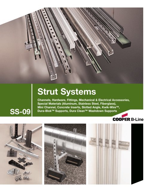
SS-09<strong>Strut</strong> <strong>Systems</strong>Channels, Hardware, Fittings, Mechanical & Electrical Accessories,Special Materials (Aluminum, Stainless Steel, Fiberglass),Mini Channel, Concrete Inserts, Slotted Angle, Kwik-Wire,Dura-Blok Supports, Dura Clean Washdown Supports
INTRODUCTION<strong>Cooper</strong> B-<strong>Line</strong>, Inc. is a leading manufacturer and fabricator of steel andaluminum products which are used in support of equipment for industrial,commercial, utility, and OEM installations. <strong>Cooper</strong> B-<strong>Line</strong> is proud of theexacting standards of research, design, engineering, and manufacturing thatgo into each and every product that comprise our metal framing productline. Our customers have access to the most complete support systemsoffered in the industry, including metal framing, cable tray, pipe hangers,slotted angle, and fasteners.Many of <strong>Cooper</strong> B-<strong>Line</strong>’s products are listed by the Underwriter’sLaboratories, Inc. All <strong>Cooper</strong> B-<strong>Line</strong> products are manufactured to meetor exceed MFMA and other industry standards set for their design andmanufacture.The majority of <strong>Cooper</strong> B-<strong>Line</strong> products are produced in four modernplants consisting of approximately 900,000 square feet. These facilitiesare located in Highland, Illinois; Troy, Illinois; Reno, Nevada; andSherman, Texas. Regional sales and distribution centers are locatedthroughout the United States stocking standard <strong>Cooper</strong> B-<strong>Line</strong> productsfor quick service and delivery.This catalog is designed to be helpful to engineers and contractors inthe application and selection of strut products for construction andmaintenance.If a unique application requires a special product not included in thiscatalog. <strong>Cooper</strong> B-<strong>Line</strong> engineering personnel are ready to furnish designconsultation and realistic cost estimates. In addition, sales representativeswith engineering know-how are located throughout the United States andabroad for your convenience.<strong>Cooper</strong> B-<strong>Line</strong>, Inc.509 West Monroe StreetHighland, Illinois 62249-0326Phone: 800-851-7415www.cooperbline.com© 2009 <strong>Cooper</strong> B-<strong>Line</strong>
New <strong>Products</strong>DURA-BLOKROOFTOP SUPPORTSPgs. 136-143DB SeriesDB6 SeriesDB10 SeriesDBE10 SeriesDBR10-12DBM SeriesDB__DS SeriesDBR SeriesDURA CLEANWASHDOWN SUPPORTSPg. 144-149U-BoltsDura Clean ChannelDura CleanWall Mount RailsHardwareThreaded RodSpacersI
New <strong>Products</strong>ARMAFIX ® CLAMPS& ACCESSORIESPg. 120StopCondensationLeaksArmaflex ®InsulationTapeClamp & Insert AssemblyIncludes: Insert, Clamp, and HardwareKWIKWIRE & ACCESSORIESPg. 57Insert OnlyUsed with B-<strong>Line</strong>Pipe Hangers(Sold Separately)KwikWireWire RopeKwikPak(Includes clamps & wire rope)KwikWire ClampsAHHK- 1 /4 & AHHK- 3 /8AIR HANDLER HANGING KITPg. 215KwikWire CutterHOT RODSPg. 56Air Duct Corner ProtectorII
BTS22THTELESCOPING CHANNELPg. 38 & 39B22SHASLOTTED BACK-TO-BACKCHANNELPg. 41Product ShowcaseBK__H112CHANNEL WITH 9 /16” HOLESON 1 1 /2” CENTERS & CUTTINGMARKS ON 1 1 /2” CENTERSPg. 42B__S58, B__M, B__H25CHANNELSPg. 42 & 43DCN3/8CONVEYOR NUTPg. 52B650SEISMIC RETROFIT BRACKETPg. 70BxxS58BxxMBxxH25UTILITY POLE BRACKETPgs. 90 & 91B852S-W-DB802DB810B816B812B809BIII
Product ShowcasePLASTIC END CAPsPgs. 96 & 97B823SeriesP CLAMPSO.D. SIZE .250”-2.750”Pg. 117B852B825SeriesB822AVIBRACLAMP ®O.D. SIZE 1 /4”-6 1 /8”PIPE SIZE 1 /4”-6”Pg. 118 & 119BVS-12 & BVS-120VIBRA STRIP FOR 1 5 /8” WIDECHANNELPg. 121B2417 & B2417-CTSTRUT MOUNTED PIPE GUIDEPg. 123Stainless Steel & AluminumPgs. 164 - 169FiberglassPgs. 170 - 187Slotted AnglePgs. 210 - 215IV
Table of ContentsIntroduction . . . . . . . . . . . . . . . . . . . . . . . . . . . . . 2-3Technical DataMaterials . . . . . . . . . . . . . . . . . . . . . . . . . . . . . . . 4Finishes . . . . . . . . . . . . . . . . . . . . . . . . . . . . . . 5-6Welding . . . . . . . . . . . . . . . . . . . . . . . . . . . . . . . . 7Corrosion . . . . . . . . . . . . . . . . . . . . . . . . . . . . . 8-9Design of <strong>Strut</strong> <strong>Systems</strong> . . . . . . . . . . . . 10-12Recommended Specification . . . . . . . . . . . 13Channel & CombinationsInfo. & Specifications . . . . . . . . . . . . . . . . . 14Selection Chart . . . . . . . . . . . . . . . . . . . . . . . . 15B11 Channel . . . . . . . . . . . . . . . . . . . . . . . 16-17B12 Channel . . . . . . . . . . . . . . . . . . . . . . . 18-19B22 Channel . . . . . . . . . . . . . . . . . . . . . . . 20-23B24 Channel . . . . . . . . . . . . . . . . . . . . . . . 24-25B26 Channel . . . . . . . . . . . . . . . . . . . . . . . 26-27B32 Channel . . . . . . . . . . . . . . . . . . . . . . . 28-29B42 Channel . . . . . . . . . . . . . . . . . . . . . . . 30-31B52 Channel . . . . . . . . . . . . . . . . . . . . . . . 32-33B54 Channel . . . . . . . . . . . . . . . . . . . . . . . 34-35B56 Channel . . . . . . . . . . . . . . . . . . . . . . . 36-37Telescoping Channel . . . . . . . . . . . . . . . 38-39Channel Hole Patterns . . . . . . . . . . . . . 40-43Channel Hole Punch . . . . . . . . . . . . . . . . . . . 43Channel Nuts & HardwareInfo. & Specifications . . . . . . . . . . . . . . . . . 44Channel NutsSelection Charts . . . . . . . . . . . . . . . . . 45-49Slip & Pull-out Load Charts . . . . . . 50-51Other Hardware . . . . . . . . . . . . . . . . . . . . 52-56KwikWire & Accessories . . . . . . . . . . . 57<strong>Strut</strong> FittingsInfo. & Specifications . . . . . . . . . . . . . . . . . 58Flat Plate Fittings . . . . . . . . . . . . . . . . . . 59-6190° Angle Fittings . . . . . . . . . . . . . . . . . . 62-67Angular Fittings . . . . . . . . . . . . . . . . . . . . 68-70Braces . . . . . . . . . . . . . . . . . . . . . . . . . . . . . . . . . 71Clevis Fittings . . . . . . . . . . . . . . . . . . . . . . . . . 72U-Fittings . . . . . . . . . . . . . . . . . . . . . . . . . . 73-76Z-Fittings . . . . . . . . . . . . . . . . . . . . . . . . . . 77-79Wing Fittings . . . . . . . . . . . . . . . . . . . . . . 80-82Post Bases . . . . . . . . . . . . . . . . . . . . . . . . . 83-84Brackets . . . . . . . . . . . . . . . . . . . . . . . . . . . 85-91Miscellaneous Fittings . . . . . . . . . . . . . 92-97Beam Clamps & AccessoriesInfo. & Specifications . . . . . . . . . . . . . . . . . 98Beam Clamps & Accessories . . . . . . 99-109Pipe/Conduit Clamps & HangersInfo. & Specifications . . . . . . . . . . . . . . . . 110Pipe Clamps . . . . . . . . . . . . . . . . . . . . . 111-117Vibra Clamps . . . . . . . . . . . . . . . . . . . . 118-119Armafix ® Clamps & Accessories . . . . . 120Vibra Cushions . . . . . . . . . . . . . . . . . . . . . . . 121Pipe Clamps . . . . . . . . . . . . . . . . . . . . . 122-126Pipe Hangers . . . . . . . . . . . . . . . . . . . . 127-128Pipe Brackets . . . . . . . . . . . . . . . . . . . . . . . . 129Pipe Rollers . . . . . . . . . . . . . . . . . . . . . 130-135Dura-Blok Rooftop SupportsInfo. & Specifications . . . . . . . . . . . . . . . . 136Base Support . . . . . . . . . . . . . . . . . . . . . . . . . 137Base Support - Channel . . . . . . . . . . 137-138Base Support - Pipe/Tubing Riser . . . . 138Base Support Riser - Channel . . . . . . . . 139Base Support Riser - Pipe Roller . . . . . 139Base Support - ‘H’ Stand . . . . . . . . 140-141Base Support - Pipe Roller . . . . . . . . . . . 142Application Photos . . . . . . . . . . . . . . . . . . . 143Dura-Clean Washdown SupportsInfo. & Specifications . . . . . . . . . . . . . . . . 144Channel . . . . . . . . . . . . . . . . . . . . . . . . . . . . . . 145Wall Mount Rails . . . . . . . . . . . . . . . . . . . . 146U-Bolts & Hardware . . . . . . . . . . . . . . . . . 147Threaded Rod & Spacers . . . . . . . . . . . . . 148Application Photos . . . . . . . . . . . . . . . . . . . 149Electrical AccessoriesInfo. & Specifications . . . . . . . . . . . . . . . . 150Selection Chart . . . . . . . . . . . . . . . . . . . . . . . 151Fluorescent Fixture Hangers . . . . . 152-154Electrical Accessories . . . . . . . . . . . 155-156Junction Boxes . . . . . . . . . . . . . . . . . . . . . . . 157<strong>Strut</strong> Joiners . . . . . . . . . . . . . . . . . . . . . 158-159Electrical Hardware . . . . . . . . . . . . . . . . . . 160Porcelain Clamps . . . . . . . . . . . . . . . . 161-162Maple Clamps . . . . . . . . . . . . . . . . . . . 162-163Aluminum & Stainless Steel MaterialsInfo. & Specifications . . . . . . . . . . . . . . . . 164Aluminum . . . . . . . . . . . . . . . . . . . . . . . 165-167Stainless Steel . . . . . . . . . . . . . . . . . . . 168-169Fiberglass MaterialsInfo. & Specifications . . . . . . . . . . . 170-171Channels . . . . . . . . . . . . . . . . . . . . . . . . 172-176Hardware . . . . . . . . . . . . . . . . . . . . . . . . 176-178Fittings . . . . . . . . . . . . . . . . . . . . . . . . . . 179-187Mini Channel & FittingsInfo. & Specifications . . . . . . . . . . . . . . . . 188Mini Channels . . . . . . . . . . . . . . . . . . . 189-190Mini Channel Nuts . . . . . . . . . . . . . . . . . . . 191Mini Fittings . . . . . . . . . . . . . . . . . . . . 191-199Econo-<strong>Strut</strong> & Fittings . . . . . . . . . . . 200-201Concrete InsertsInfo. & Specifications . . . . . . . . . . . . . . . . 202Continuous Inserts . . . . . . . . . . . . . . . 203-206Spot Inserts . . . . . . . . . . . . . . . . . . . . . . . . . . 207Insert Accessories . . . . . . . . . . . . . . . . . . . . 208Anchors . . . . . . . . . . . . . . . . . . . . . . . . . . . . . . 209Slotted AngleInfo. & Specifications . . . . . . . . . . . . . . . . 210Slotted AngleSizes . . . . . . . . . . . . . . . . . . . . . . . . . . . . . . . 211Loading Charts . . . . . . . . . . . . . . . . 212-214Slotted Angle Fittings . . . . . . . . . . . . . . . . 215Reference Data . . . . . . . . . . . . . . . . . . . . . 216-225Index . . . . . . . . . . . . . . . . . . . . . . . . . . . . . . . 226-2331
IntroductionB-<strong>Line</strong>’s metal framing support system is designed with many time-saving features. They are fully adjustable andreusable, with a complete line of channels, fittings and accessories for multi-purpose applications.Introduction• No Welding• No Drilling• Use Your ImaginationB-<strong>Line</strong> metal framing installs quickly. There is noneed for special tools. All you need is a wrenchand hacksaw. Channels and parts can be takenapart for reuse as quickly as they were assembled,yet they provide the strength of welded construction.Eliminating welding and drilling produces substantialsavings in time and labor.1. Tite-Grip channel nut may beinserted anywhere along continuousslot. Designed for easy insertion andself-alignment.2. A 90 degree turn aligns channel nutgrooves with inturned lips of thechannel.3. Position fitting over channel nut and insert bolt tostart any connection.4. With the twist of a wrench, channelnut locks its teeth firmly againstinturned lips.2
IntroductionB-<strong>Line</strong>’s Metal Framing system provides aneconomical solution for electrical, mechanicaland industrial supports with an unlimitedvariety of applications in the constructionindustry.Metal Framing Electrical Applications• Lighting Fixture Supports• Raceway <strong>Systems</strong>• Trapeze Hangers• Pipe & Conduit Supports• Cable Tray Supports• Beam AdjustmentsIntroductionMetal Framing Mechanical Applications• Piping Racks• Tunnel Pipe Stanchions• Concrete Inserts• Beam Attachments• Pipe RisersMetal Framing Industrial Applications• Racks and Shelving• Partitions• Production <strong>Line</strong> Supports• Trolley <strong>Systems</strong>• Wall Framing3
Technical DataMATERIALSTechnical DataCarbon SteelChannels made from high-quality carbonsteel are continuously roll formed to precisedimensions. By cold working the steelmechanical properties are increased,allowing lightweight structures to carry therequired load. Corrosion resistance ofcarbon steel varies widely with coating andalloy. See “Finishes” for more detailedinformation.Stainless SteelStainless steel channel is available in AISIType 304 or 316 material. Both arenon-magnetic and belong to the austeniticstainless steels group, based on alloycontent and crystallographic structure. Likecarbon steel, stainless steel exhibitsincreased strength when cold worked byroll-forming.Several conditions make the use ofstainless steel ideal. These include reducinglong term maintenance costs, high ambienttemperatures, appearance, and stablestructural properties such as yield strength,and high creep strength.Type 304 resists most organic chemicals,dyestuffs and a wide variety of inorganicchemicals at elevated or cryogenictemperatures. Type 316 contains slightlymore nickel and adds molybdenum to giveit better corrosion resistance in chloride andsulfuric acid environments. More specific\information concerning the differencesbetween types 304 and 316 is availablefrom B-<strong>Line</strong>.AluminumB-<strong>Line</strong>’s standard aluminum channel isextruded from aluminum alloy 6063-T6.<strong>Strut</strong> fittings are made from aluminumalloy 5052-H32.The high strength to weight ratio of channelmade of aluminum greatly reduces theoverall cost of installation through ease ofhandling and field cutting.Aluminum owes its excellent corrosionresistance to its ability to form an aluminumoxide film that immediately reforms whenscratched or cut. In most outdoorapplications, aluminum has excellentresistance to “weathering”. The resistanceto chemicals, indoor or outdoor, can best bedetermined by tests conducted by the userwith exposure to the specific conditions forwhich it is intended. The corrosionresistance of aluminum to some commonlyknown chemicals is shown in the CorrosionChart. For further information, contactB-<strong>Line</strong> <strong>Systems</strong>, Inc. or the AluminumAssociation.FiberglassB-<strong>Line</strong> offers two fire retardant (FR) resinsfor strut systems, polyester and vinyl ester.Both resins are ideal for corrosiveenvironments or nonconductive applicationswith moderate strength requirements.Some common types of environmentswhere Vinyl Ester Resins are recommended,that Poly Esters are not, are paper mills,most any metal plating operation and anycondition with concentrated levels ofChlorine, [ Cl - ]. Please consult ourfiberglass corrosion resistance charts onpg. 173 for specific chemicalrecommendation data.Unlike other base materials depicted in thiscatalog, fiberglass exhibits unique physicalproperty changes when operating inelevated temperature conditions, that are afraction of increase compared to steel oraluminum. This being true, B-<strong>Line</strong> advisesagainst using fiberglass in temperaturesgreater than 200° F.Please refer to the "Corrosion ResistanceGuide" below for specific applications.B-<strong>Line</strong> Fiberglass <strong>Strut</strong> systems aremanufactured from glass fiber-reinforcedplastic shapes that meet ASTM E-84, Class 1Flame Rating and self-extinguishingrequirements of ASTM D-635. A surface veilis applied during pultrusion to insure aresin-rich surface and ultraviolet resistance.While polyester is sufficient for most uses,vinyl ester is suitable for a broader range ofenvironments.B-<strong>Line</strong> B22 SS6 87401A6B-<strong>Line</strong> Steel <strong>Strut</strong> is stamped with:Traceable to the steel’s originMaterial/FinishB-<strong>Line</strong> part number designationCompany Name4
Technical DataFINISHESZinc CoatingsZinc protects steel in two ways. First itprotects the steel as a coating and second asa sacrificial anode to repair bare areas suchas cut edges, scratches, and gouges. Thecorrosion protection of zinc is directlyrelated to its thickness and the environment.This means a .2 mil coating will last twiceas long as a .1 mil coating in the sameenvironment.Galvanizing also protects cut and drilled edges.ZnZnFeFeZnOElectrogalvanized ZincElectrogalvanized Zinc (also known as zincplated or electroplated) is the process bywhich a coating of zinc is deposited on thesteel by electrolysis from a bath of zincsalts.A rating of SC3, B-<strong>Line</strong>’s standard,provides a minimum zinc coating thicknessof .5 mils (excluding hardware, which isSC1 = .2 mils).When exposed to air and moisture, zincforms a tough, adherent, protective filmconsisting of a mixture of zinc oxides,hydroxides, and carbonates. This film is initself a barrier coating which slowssubsequent corrosive attack on the zinc.This coating is usually recommended forindoor use in relatively dry areas, as itprovides ninety-six hours protection in saltspray testing per ASTM B117.Chromium/ ZincChromium/ Zinc is a corrosion resistantcomposition, which was developed toprotect fasteners and small bulk items forautomotive use. The coating applicationshave since been extended to larger parts andother markets.Chromium/Zinc composition is an aqueouscoating dispersion containing chromium,proprietary organics, and zinc flake.This finish provides 500 hours protection insalt spray testing per ASTM B117.Pre-Galvanized Zinc(Mill galvanized, hot dip mill galvanized orcontinuous hot dip galvanized) Pregalvanizedsteel is produced by coatingcoils of sheet steel with zinc bycontinuously rolling the material throughmolten zinc at the mills. This is also knownas mill galvanized or hot dip millgalvanized. These coils are then slit to sizeand fabricated by roll forming, shearing,punching, or forming to produce B-<strong>Line</strong>pre-galvanized strut products.The G90 specification calls for a coating of.90 ounces of zinc per square foot of steel.This results in a coating of .45 ounces persquare foot on each side of the sheet. Thisis important when comparing this finish tohot dip galvanized after fabrication.During fabrication, cut edges and weldedareas are not normally zinc coated;however, the zinc near the uncoated metalbecomes a sacrificial anode to protect thebare areas after a short period of time.Hot Dip Galvanized AfterFabrication (Hot dip galvanized orbatch hot dip galvanized)Hot dip galvanized strut products arefabricated from steel and then completelyimmersed in a bath of molten zinc. Ametallic bond occurs resulting in a zinccoating that completely coats all surfaces,including edges and welds.Another advantage of this method is coatingthickness. <strong>Strut</strong> products that are hot dipgalvanized after fabrication have aminimum thickness of 1.50 ounces persquare foot on each side, or a total 3.0ounces per square foot of steel, according toASTM A123.The zinc thickness is controlled by theamount of time each part is immersed in themolten zinc bath as well as the speed atwhich it is removed. The term "doubledipping" refers to parts too large to fit intothe galvanizing kettle and, therefore, mustbe dipped one end at a time. It does notrefer to extra coating thickness.The layer of zinc which bonds to steelprovides a dual protection against corrosion.It protects first as an overall barriercoating. If this coating happens to bescratched or gouged, zinc's secondarydefense is called upon to protect the steel bygalvanic action.Hot-Dip Galvanized After Fabrication isrecommended for prolonged outdoorexposure and will usually protect steel for20 years or more in most atmosphericenvironments and in many industrialenvironments. For best results, a zinc richpaint (available from B-<strong>Line</strong>) should beapplied to field cuts. The zinc rich paint willprovide immediate protection for theseareas and eliminate the short time period forgalvanic action to “heal” the damagedcoating.Technical DataAnticipated Life of Zinc Coatings In Various Atmospheric Environments4036Hot Dip GalvanizedPre-Galvanized= Zinc Coating 1.50 Oz./Ft. 2 (.0026” Thick)= Zinc Coating 0.45 Oz./Ft. 2 (.00075” Thick)LifeinYears30202925211810108765311RuralTropicalMarineTemperatureMarineSuburbanUrbanHighlyIndustrialEnvironment5
Technical DataTechnical DataDura-Green ® and Dura-Copper ®Epoxy CoatingsDura-Green and Dura-Copper epoxycoatings are water borne epoxy coatingsapplied to B-<strong>Line</strong> products by a preciselycontrolled cathodic electro-depositionprocess. This process is accomplished usinga conveyor to transport channel and fittingsthrough several cleaning, phosphatizing andapplication stages prior to being baked (Seediagram below).This custom-designed paint system is usedfor painting all channels, channelcombinations, slotted angle, and fittings.Samples are selected on a routine basis forSalt Spray (fog) testing to verify the qualityof the finish. These tests are performed inaccordance with ASTM B117 and evaluatedand related according to ASTM D1654(Tables 1 & 2).The Dura-Green and Dura-Copper Epoxycoatings have been tested and listed byUnderwriters Laboratories in accordancewith “Standard for Surface Metal Racewayand Fittings, UL5” and “Standard for PipeHanger Equipment for Fire ProtectionService, UL203”.Due to Dura-Green’s organically basedcomposition, it seats itself into poroussurfaces more completely and efficientlythan zinc coatings. As these porous cavernsare filled along the material profile, theouter finished surface demonstrates anincreased smooth uniform plane whichproduces considerably less off-gasing whentested.B-<strong>Line</strong>’s Dura-Green channel meets orexceeds 100 level clean room standards.This was confirmed by testing the channelin accordance with Boeing (PCL)Standards, which are more stringent andcomplete than ASTM E595-93. Dura-Greenwas found to be a superior finish, due inpart to its proven application process.PVC CoatingAnother of the corrosion resistant coatingsoffered by B-<strong>Line</strong> is PVC (polyvinylchloride), applied over steel or aluminumchannel and fittings. The PVC coatingprocess begins by cleaning the productthoroughly. A bonding coat is applied to thepart and then preheated to a temperatureabove the melting point of the coatingpowder. The product is then passed througha fluidized bed of vinyl plastic powderwhere the powder particles melt, adhere andflow out to form a smooth continuouscoating. The thickness is controlled by thebase metal temperature and the immersiontime in the bed. It is then post-heated tocomplete the fusion of the outer surfaces.The standard coating thickness of B-<strong>Line</strong>’sPVC coated products is 15 mils (.380 mm),plus or minus 5 mils (.125 mm). Since thechemistry, not the thickness of vinyl plasticPVC determines longevity, a coating of 10to 20 mils (.250 to .500 mm) is more thanadequate. If the corrosive conditions aresuch that the plasticizers are leeched out, athicker coating will do little to extend thelife of a coated product.For certain environments, a plastisol dippedPVC coating is available on request.SALT SPRAY TEST RESULTS˛ Unscribed Scribed 1 /8” (3.2) CreepageType of Finish 5% Failure (1) from Scribe (1)B-<strong>Line</strong> Dura-Green Epoxy 1000 Hours 312 HoursMill Galv. (Pre-Galv.) G90 192 Hours 288 HoursPerma-Green 438 Hours 231 HoursZinc Chromate 36 Hours 96 HoursIndustry Green (Range) 10 to 36 Hours 4 to 30 Hours(1) All salt spray (fog) tests conducted in accordance with ASTM B117 and evaluated and ratedaccording to ASTM D1654 Tables 1 & 2. Tests are performed and certified by an independenttesting laboratory.PVC coating depends totally on the conceptof encapsulation attached to the base metalby a bonding agent. If any hole ordiscontinuity occurs, the corrosive actioncan undercut the base metal to a pointwhere all that remains is the PVC.In the event of field cuts or any otherdamage to the coating, a liquid PVC patch,available from B-<strong>Line</strong>, must be applied tomaintain the integrity of the coating. Afterthe installation is complete, a thoroughinspection should be performed to assurethe absence of voids, pinholes, or cuts.DURA-GREEN ® /DURA-COPPER ® EPOXY COATING PROCESSTANK 1 TANK 2 TANK 3 TANK 4 TANK 5 TANK 6 TANK 7 TANK 8 BAKE OVENThe channel A rinse is A phosphatized The material A pre-deionized The electro- The first post The final rinse The curingand parts are applied to sealer is applied moves through rinse prepares coating tank rinse removes insures a process takes 20thoroughly remove insol- to insure corro- clear water rinse the metal for the applies a uni- any unelectri- smooth, non- minutes at acleaned and uble salts and sion resistance to remove excess cathodic electro- form coat of cally attracted blemish surface. baking temperaturephosphatized. unreacted and paint phosphates. coating. epoxy paint to solids. of 375° F (199° C).phosphates. adhesion. the entiresurface.6
Technical DataWELDINGThe welding procedures used in thefabrication of B-<strong>Line</strong> steel products arein accordance with American WeldingSociety Standards. To achieve the highestquality in our manufacturing processes, ourwelders follow standards set by AWS Code.Spot WeldingSpot welded back-to-back channel ismanufactured using a modern DC poweredresistance welder controlled by amicroprocessor. This produces a series ofspot welds with speed and consistency.Consistency is one of the most importantadvantages in specifying B-<strong>Line</strong> back-tobackchannel. Variables such as weldsequence, speed and duration are carefullycontrolled and monitored by a sophisticatedelectronic control system. A statisticalquality control program, combiningdestructive and non-destructive testing, isused by B-<strong>Line</strong> to ensure high qualitywelds.MIG WeldingMIG welded, more properly called gasmetal arc welded (GMAW) combinationchannels and fittings, are produced whenphysical dimensions or certaincombinations require a weld process otherthan automatic spot welding. The samequality control requirements are imposed onMIG welded and spot-welded products.Quality AssuranceB-<strong>Line</strong> System’s Quality AssuranceProgram has been developed andimplemented for compliance to 10CFR50appendix B and NQA-1. B-<strong>Line</strong> alsocomplies with various industry standardsand specifications. B-<strong>Line</strong> has extensiveexperience in supplying metal framingcomponents for the nuclear powergenerating industry and complies with10 CFR21.Technical DataSpot WeldMig Weld7
Technical DataTechnical DataCORROSIONAll metal surfaces are affected by corrosionDepending on the physical properties ofthe metal and the environment to which it isexposed, chemical or electromechanicalcorrosion may occur.Atmospheric CorrosionAtmospheric corrosion occurs when metalis exposed to airborne liquids, solids orgases. Some sources of atmosphericcorrosion are moisture, salt, dirt andsulphuric acid. This form of corrosion istypically more severe outdoors, especiallynear marine environments.Chemical CorrosionChemical corrosion takes place when metalcomes in direct contact with a corrosivesolution. Some factors which affect theseverity of chemical corrosion include:chemical concentration level, duration ofcontact, frequency of washing, andoperating temperature.Storage CorrosionWet storage stain (white rust) is caused bythe entrapment of moisture betweensurfaces of closely packed and poorlyventilated material for an extended period.Wet storage stain is usually superficial,having no affect on the properties of themetal.Light staining normally disappears withweathering. Medium to heavy buildupshould be removed in order to allow theformation of normal protective film. Properhandling and storage will help to assurestain-free material. If product arrives wet, itshould be unpacked and dried beforestorage. Dry material should be stored in awell ventilated “low moisture” environmentto avoid condensation formation. Outdoorstorage is undesirable, and should beavoided whenever possible.Galvanic CorrosionGalvanic corrosion occurs when two ormore dissimilar metals are in contact in thepresence of an electrolyte (ie. moisture).An electrolytic cell is created and the metalsform an anode or a cathode depending ontheir relative position on the GalvanicSeries Table. The anodic material will bethe one to corrode. Anodic or cathodiccharacteristics of two dissimilar metals willdepend on the type of each material. Forexample: If zinc and steel are in contact, thezinc acts as the anode and will corrode; thesteel acts as the cathode, and will beprotected. If steel and copper are incontact, the steel is now the anode and willcorrode.The rate at which galvanic corrosion occursdepends on several factors:GALVANIC SERIES IN SEA WATERAnodic EndMagnesiumMagnesium AlloysZincBerylliumAluminum - Zinc Alloys (7000 series)Aluminum - Magnesium Alloys (5000 series)Aluminum (1000 series)Aluminum - Magnesium Alloys (3000 series)Aluminum - Magnesium - Silicon Alloys (6000 series)CadmiumAluminum - Copper Alloys (2000 series)Cast Iron, Wrought Iron, Mild SteelAustenitic Nickel Cast IronType 410 Stainless Steel (active)Type 316 Stainless Steel (active)Type 304 Stainless Steel (active)Naval Brass, Yellow Brass, Red BrassTinCopperLead-Tin SoldersAdmiralty Brass, Aluminum BrassManganese BronzeSilicon BronzeTin BronzeType 410 Stainless Steel (passive)Nickel - SilverCopper Nickel AlloysLeadNickel - Aluminum BronzeSilver SolderNickel 200SilverType 316 Stainless Steel (passive)Type 304 Stainless Steel (passive)Incoloy 825Hastelloy BTitaniumHastelloy CPlatinumGraphiteCathodic EndMore AnodicMetals in descending order of activity in the presence of an electrolyte.1. The relative position on the GalvanicSeries Table - the further apart materials arein the Galvanic Series Table, the greater thepotential for corrosion of the anodicmaterial.2. The amount and concentration ofelectrolyte present - an indoor, dryenvironment will have little or no galvaniccorrosion compared to a wet atmosphere.3. The relative size of the materials - asmall amount of anodic material in contactwith a large cathodic material will result ingreater corrosion. Likewise, a large anodein contact with a small cathode willdecrease the rate of attack.8
Technical DataType 304 Type 316 ZincChemical Aluminum Dura-Green PVC Stainless Stainless Coated SteelAcetic Acid 10% R NR R R R NRAcetic Acid 2% R F R R R NRAcetone R R NR R R RAmmonium Hydroxide-Conc. R R R R R –Ammonium Hydroxide 10% F R R R R –Ammonium Hydroxide 2% R R R R R –Benzene R R NR R R –Bromine Water NR R R NR NR –Butanol (Butyl Alcohol) R R R R R RCarbon Disulfide R R NR R R –Carbon Tetrachloride F R F R R –Chlorine Water R R R NR F RCutting Oil – R – – – –Diethanolamine R R NR – – NREthanol R R R R R REthyl Acetate R R NR – – REthylene Dichloride F R NR – – RFormaldehyde 20% R R R R R RGasoline R R R R R RGlycerine R R R R R RHousehold Detergent 10% F R R R R –Hydrochloric Acid 40% NR NR R NR NR NRHydrochloric Acid 10% NR F – NR NR NRHydrochloric Acid 2% NR F – NR NR NRHydrogen Peroxide 30% R NR R R R –Hydrogen Peroxide 3% R R – R R –Hydrogen Sulfide (Gas) R R R F R –JP-4 Jet Fuel R R R R R –Lactic Acid 85% F R R NR – –Latex R R – R R NRLinseed Oil Fatty Acid R F R R R –Methanol R R R R R RMethyl Ethyl Ketone R R NR – – RMethyl Isobutyl Ketone R R NR – – RMineral Spirits R R – – – –Motor Oil-10W R R R R R RNaphtha, VM&P R R R R R RNitric Acid 2% F NR R R R –Perchloroethylene R R – – – NRPetroleum Ether – R – R R RPhenol 10% R R NR R R RPhosphoric Acid 2% F NR R R R NRPotassium Hydroxide 50% NR R R R R –Potassium Hydroxide 10% NR R R R R –Potassium Hydroxide 2% NR R R R R –Sodium Chloride 25% F R R R R FSodium Hydroxide 50% NR R R R R NRSodium Hydroxide 10% NR R R R R FSodium Hydroxide 2% NR R R – – –Sodium Hypochlorite-C1. 10% F R R – – –Sodium Hypochlorite-C1. 6% F R R NR R –Sulfuric Acid 2% F NR R NR R NRTall Oil Fatty Acid (Syfate 94) R R R – – –Tannic Acid 50% F R R R R –Water-Deionized R R R R R FWater-Sea F F R R R FWater-Tap R R R F F RXyol R R NR – – –Fiberglass corrosion chart on page 171.The corrosion data given in this table is for general comparison only.The presence of contaminates and the effect of temperature in chemical environments can greatly affect the corrosion of any material.B-<strong>Line</strong> strongly suggests that field service tests or simulated laboratory tests using actual environmental conditions be conducted in orderto determine the proper materials and finishes to be selected.R=RecommendedF=May be used under some conditionsNR=Not Recommended–Information not availableTechnical Data9
Technical DataTechnical DataDESIGN OFSTRUT SYSTEMSBeamsBeams are usually defined as horizontalmembers which are subjected to verticalloads such as shelves, platforms or supportsfor pipes, conduits or cable trays. Thefollowing is a brief overview of commonbeam configurations:Simple BeamAn example of a simple beam is a length ofchannel placed across two cylinders. Whena load is applied, the channel will supportthe load because of its stiffness. Thecylinders serve to support the channel, butdo not interfere with its natural tendency toflex or bend. Simple beam analysis is usedalmost universally for beam comparisons,even though it is seldom practical in fieldinstallations.A cable tray or conduit trapeze hangerclosely resembles a simple beam.Point LoadCantilever BeamCantilever beams are often viewed asvariations of a fixed beam, but they havespecial characteristics of their own. Oneend of the channel is firmly attached to arigid support while the other end remainscompletely free.A shelf bracket is an example of acantilever beam.Continuous BeamThis beam configuration is commonly usedin lighting installations. The continuous beampossesses traits of both the simple and fixedbeams. When equal loads are applied to allspans simultaneously, the counter-balancingeffect of the loads on both sides of asupport restricts the movement of thechannel at the support, similar to that ofthe fixed beam. The end spans behavesubstantially like simple beams.DeflectionDeflection, commonly referred to as “sag”,is inherent in applying a load to a beamand cannot be avoided. Any and all beamswill deflect when loaded. The amount ofdeflection will vary depending upon thematerial and the stiffness or moment ofinertia. The deflection equations in thissection show that increasing the stiffnesscan be increased by a variety of methods.Increasing the depth of the channel is themost direct method.Point LoadThe material used affects deflection in amanner which is significantly differentfrom the way in which it affects loadcapacity. The deflection under load isinversely proportional to a material propertyknown as the “modulus of elasticity”designated by “E”.The modulus of elasticity is dependent uponthe basic composition of the material and isnot necessarily related to the material’sstrength.Fixed BeamThis type of fixed support restricts themovement of the ends of the channel whena load is applied. Because of this, thestiffness of the channel at the ends andcenter is employed to resist the load. Theresult is a load capability which is greaterthan that of an identical simple beam.The fixed beam can be approximated bybolting or welding a length of channel torigid supports.Continuous beam installations can typicallysupport 20% more load than a simple beamof the same span with approximately halfthe deflection.Therefore, simple beam data should be usedfor a general comparison only. An exampleof this configuration is found in a long runof channel when installed across severalsupports to form a number of spans.10
Technical DataSafety FactorThe design loads given for strut beam loadsare based on a simple beam condition usingallowable stress of 25,000 psi. Thisallowable stress results in a safety factor of1.68. This is based upon a virgin steelminimum yield strength of 33,000 psi coldworked during rolling to an average yieldstress of 42,000 psi.Aluminum typically has an elastic moduluswhich is 1 /3 that of steel even though theymay have identical strength. As a result, thedeflection of aluminum channel will bethree times that of steel channel under equalloading. In areas where structures will besubject to general viewing, deflection canproduce a displeasing effect. To theuntrained eye, a sagging channel mayappear to be a result of poor design orexcessive loading. This is not usually thecase. Many properly designed channelinstallations will show a noticeabledeflection at their designed loads. In areaswhere cosmetics are not important,deflection should not be a factor. Designingan entire installation based on minimaldeflection could result in an over designedstructure. This translates into increasedmaterial and installation cost. Wherecosmetics are important, it may benecessary to limit the deflection to anaesthetically pleasing amount. This“acceptable deflection” amount is typicallygiven as a fraction of the span. 1/240 spandeflection is typically the limit where theamount of deflection appears negligible. Forexample, a beam span of 240” would beallowed 1” (240/240) of deflection at themid point. A 120” span would only beallowed 1 /2” (120/240) of deflection. Themaximum load for the channel must belimited in order to remain under thesedeflection requirements. The allowable loadresulting in 1/240 span deflection is postedin the beam load chart for each channelsize.For even more stringent deflectionrequirements, an allowable load is listed inthe beam load charts which results in 1/360span deflection. This amount of deflectionis sometimes used for beams in finishedceilings that are to be plastered.Twisting & Lateral BracingLoading of strut on long spans can causetorsional stress, resulting in the tendency ofthe strut to twist or bend laterally. Thisphenomenon reduces the allowable beamloads as shown in the beam loading charts.It is recommended that long spans besupported in a manner to prevent twisting(fixed ends), and that the channel haveadequate lateral bracing. Many typical strutapplications provide this support andbracing inherently. Piping, tubing, cabletrays, or conduits mounted to the strut withstraps and clamps prevent twisting or lateralmovement. If no such lateral support exists,contact the factory for loadingrecommendations.ColumnsColumns are vertical members which carryloads in compression. One commonexample of a channel column is the verticalmembers of a storage rack.In theory, a column will carry a load equalto its cross sectional area multiplied by theultimate compressive stress of the materialof which the column is made. In reality,there are many factors affecting the loadcapacity of a column, such as the tendencyto buckle or twist laterally (torsionalflexuralbuckling), the type of connectionat the top or bottom, the eccentricity of theload application, and materialimperfections. Several of these failuremodes have been considered in theallowable column load tables shown in the“Channel” section of this catalog.B-<strong>Line</strong> strongly recommends that theengineer perform a detailed study of themany variable conditions before theselection process begins.Design Factors to be ConsideredThe loading capacity of channel dependsprimarily on the material, its cross-sectionaldesign, and the beam or column loadingconfiguration. It should be noted that if twolengths of channel have identical designsand configurations, the one made of thestronger base material will support a largerload. Therefore, any comparison of channelshould begin by determining whether thematerials are approximately equal instrength.The column loading chart for each channellists the allowable load for each channel incompression. This load varies dependingon the support condition or “K-factor”.Several “K-factors” are listed, whichcorrespond to the following supportconditions:K = .8 pinned top - fixed bottomK = .65 fixed top - fixed bottomK = 1.0 pinned top - pinned bottomK = 1.2 free top - fixed bottomThere are a number of physical propertieswhich are important to the complete designof a channel member; the “sectionmodulus” designated as “Sx” or “Sy”,“moment of inertia” designated by “Ix” or“Iy”, and the “radius of gyration” which isgiven as “rx” or “ry”.Every structural material has its ownmaximum or ultimate stress, which isusually expressed in “pounds per squareinch” (pascals). Any load which causes amember to fail is referred to as its“ultimate” load. In order to prevent channelfrom being accidentally loaded up to orbeyond its ultimate load, a safety factor isincluded into the design. The ultimate loadis divided by the safety factor to obtain the“recommended” or “allowable” workingload.When evaluating channel under variousbeam conditions, it is often more convenientto compare in terms of the ultimate orrecommended “bending moment”. Simpleequations show the stress is directlyproportional to the bending moment.Therefore, comparing bending momentscan save time in repeated calculations. Thechart containing Formulas on CommonBeam Loadings (following page) showshow to calculate the bending moment forvarious configurations and load conditions.It should be noted that the bending momentis usually not constant, but varies along thelength of the span. However, the channelmust be designed for a single point, whichis the point of maximum bending moment.For information regarding dynamic orseismic design, contact B-<strong>Line</strong>’s HomeOffice.GENERALINFORMATIONTorqueThe torque values given throughout thecatalog are to be used as a guide only. Therelationship between the applied torque ortorque wrench reading and the actualtension created in the bolt may besubstantially different. For example, a drynon-lubricated bolt with a heavy platingmay rate 50% as efficient as a bolt which islubricated with a mixture of heavy oil andgraphite. Other important factors affectingtorque-tension relationships include frictionunder the bolt head or nut, hole tolerances,and torque wrench tolerances. Accuracy ofmany commercial torque wrenches mayvary as much as plus or minus 25%.Charts and TablesCharts and tables in this section arecompiled from information published bynationally recognized organizations and areintended for use as a guide only. B-<strong>Line</strong>recommends that users of this informationdetermine the validity of such informationas applied to their own application.Technical Data11
Technical DataThe data shown in the beam load charts for appropriate channels on page(s) 17 thru 39 is for simply supported, single span beams with auniformly distributed load. For other loading and/or support conditions, use the appropriate factor from the chart below.LoadDeflectionLOAD AND SUPPORT CONDITIONFactorFactorSimple Beam - Uniform Load 1.00 1.00SpanSimple Beam - Concentrated Load at Center .50 .80Simple Beam - Two Equal Concentrated Loads at 1 /4 Points 1.00 1.10Technical DataBeam Fixed at Both Ends - Uniform Load 1.50 .30Beam Fixed at Both Ends - Concentrated Load at Center 1.00 .40Cantilever Beam - Uniform Load .25 2.40Cantilever Beam - Concentrated Load at End .12 3.20Continuous Beam - Two Equal Spans - Uniform Load on One Span 1.30 .92SpanSpanContinuous Beam - Two Equal Spans - Concentrated Load on Both Spans 1.00 .42Continuous Beam - Two Equal Spans - Concentrated Load at Center of One Span .62 .71Continuous Beam - Two Equal Spans - Concentrated Load at Center of Both Spans .67 .48EXAMPLES:PROBLEM:Calculate the maximum allowable load and correspondingdeflection of a simply supported B22 beam with a concentratedload at midspan as shown.PROBLEM:Calculate the maximum allowable load and correspondingdeflection of a cantilever B52 beam with a uniformly distributedload.96”SOLUTION:SOLUTION:From beam load chart for B22 (page 22), maximum allowableFrom beam load chart for B52 (page 33), maximum allowableLoad is A and the corresponding deflection is B. load is A and the corresponding deflection is B.Multiplying by the appropriate factors shown in the chart above.Multiplying by the appropriate factors shown in chart above.LOAD = A x load factor = _______DEFLECTION = B x deflection factor =LOAD = A x load factor = _______DEFLECTION = B x deflection factor = _______12
RECOMMENDED BOLTED METALFRAMING SPECIFICATIONBrackets [ ] indicate alternativespecifications which may be substituted bythe project engineer.PART 1 - GENERAL1.01 WORK INCLUDEDA. Continuous slot, bolted framing channelsand all associated fittings and hardware.B. Trapeze type supports for cable tray,conduit, pipe and other similar systems.C. Use of bolted metal framing as a surfacemetal raceway.1.02 REFERENCESA. ASTM A108 - Specification for SteelBars, Carbon, Cold Finished, StructuralQuality.B. ASTM A123 - Specification for Zinc(hot-dip galvanized) Coatings on <strong>Products</strong>Fabricated from Rolled, Pressed, andForged Steel Shapes, Plates, Bars andStrips.C. ASTM A1011, 33,000 PSI min. yield -Specification for Steel, Sheet and Strip,Carbon, Hot-Rolled, Structural Quality.D. ASTM B633 - Specification forElectrodeposited Coatings of Zinc on Ironand Steel.E. ASTM A653 33,000 PSI min. yield G90- Specification for Steel Sheet, Zinc Coated(Galvanized) by the Hot-Dip Process.F. ASTM A1018 - Standard Specificationfor Steel, Sheet and Strip, Heavy-ThicknessCoils, Carbon, Hot-Rolled, StructuralQuality.G. MFMA - Metal Framing StandardsPublication, MFMA-1.1.03 QUALITY ASSURANCEA. Manufacturers : Firms regularly engagedin the manufacture of bolted metal framingof the types required, whose products havebeen in satisfactory use in similar servicefor not less than 5 years.B. A material heat code number shall bestamped on all strut and fittings. This isrequired to maintain traceability of theproduct to the material test reports to theASTM standard.C. For stainless steel items, the part numbershall contain a material designator(EXAMPLE: B-<strong>Line</strong> B22SS6 for type 316or B22SS4 for type 304), or a separatestamp shall be included to reference thetype of material used.D. MFMA Compliance: comply with thelatest revision of MFMA StandardPublication Number MFMA-3, “MetalFraming”.E. NEC Compliance: Comply with thelatest revision NFPA 70 - Article 352“Surface Metal Raceways and SurfaceNonmetallic Raceways”.F. UL Compliance: Comply with UL“Standard for Surface Metal Raceway andFittings”.1.04 SUBMITTALSA. Submit drawings of strut and accessoriesincluding clamps, brackets, hanger rods andfittings.B. Submit manufacturer’s product data onstrut channels including, but not limited to,types, materials, finishes, gauge thicknessand hole patterns. For each different strutcross section, submit cross sectionalproperties including Section Modulus (Sx)and Moment of Inertia (Ix).1.05 DELIVERY, STORAGE ANDHANDLINGA. Deliver strut systems and componentscarefully to avoid breakage, denting, andscoring finishes. Do not install damagedequipment.B. Store strut systems and components inoriginal cartons and in clean dry space;protect from weather and constructiontraffic.PART 2 - PRODUCTS2.01 ACCEPTABLEMANUFACTURERSA. Manufacturer: Subject to compliancewith these specifications, strut systems tobe installed shall be as manufactured byB-<strong>Line</strong> <strong>Systems</strong>, Inc. [or engineer approvedequal.]2.02 STRUT CHANNELS ANDCOMPONENTSA. General: <strong>Strut</strong> shall be 1 5 /8” wide invarying heights and welded combinationsas required to meet load capacities anddesigns indicated on the drawings.B. Material and Finish: Material and finishspecifications for each strut type are asfollows:1. Aluminum: <strong>Strut</strong> shall be manufacturedof extruded aluminum alloy 6063-T6. Allfittings and hardware shall be zinc platedaccording to ASTM B633. For outdoor use,all fittings and hardware shall be stainlesssteel Type 316 [Type 304] or chromiumzinc, ASTM F1136 Gr. 3.2. Epoxy Painted: <strong>Strut</strong> shall be made fromsteel meeting the minimum mechanicalproperties of ASTM A1011 33,000 PSI minyield, then painted with water born epoxyTechnical Dataapplied by a cathodic electro-depositionprocess. Fittings shall be manufactured fromsteel meeting the minimum requirements ofASTM A1018 33,000 PSI min. yield. Thefittings shall have the same epoxy finish asthe strut. Threaded hardware shall be zincplated in accordance with ASTM B633Service Class 1 (SC1). Service Class 1 isnot an acceptable coating for fittings orcomponents other than threaded hardware.3. Pre-Galvanized Steel: <strong>Strut</strong> shall be madefrom steel meeting the minimummechanical properties of ASTM A65333,000 PSI min. yield, mill galvanizedcoating designation G90. Fittings shall bemanufactured from steel meeting theminimum requirements of ASTM A101833,000 PSI min. yield and zinc plated inaccordance with ASTM B633 service class3 (SC3). Threaded hardware shall be zincplated in accordance with ASTM B633Service Class 1 (SC1). Service Class 1 isnot an acceptable coating for fittings orcomponents other than threaded hardware.4. Hot-Dip Galvanized Steel: <strong>Strut</strong> shall bemade from steel meeting the minimummechanical properties of ASTM A101133,000 PSI min. yield and shall be hot-dipgalvanized after fabrication in accordancewith ASTM A123. Fittings shall bemanufactured from steel meeting theminimum requirements of ASTM A101833,000 PSI min. yield, and hot-dipgalvanized after fabrication in accordancewith ASTM A123. All hardware shall bestainless steel Type 316 [Type 304] orchromium zinc ASTM F1136 Gr. 3. All hotdipgalvanized after fabrication productsmust be returned to point of manufactureafter coating for inspection and removal ofall sharp burrs.5. Stainless Steel: All strut, fittings andhardware shall be made of AISI Type 316[Type 304] stainless steel as indicated.Channels must be identified as required inprevious section 1.03 Quality Assurance.PART 3 - EXECUTION3.01 INSTALLATIONA. Install strut as indicated; in accordancewith equipment manufacturer’srecommendations, and with recognizedindustry practices.B. All nuts and bolts shall be tightened tothe following values.Bolt Size Torque (ft-lbs)1 /4-20 65 /16-18 113 /8-16 191 /2-13 50Technical Data13
Metal Framing ChannelsChannel & CombinationsChannelB-<strong>Line</strong>’s metal framing channel is cold formed on ourmodern rolling mills from 12 Ga. (2.6mm), 14 Ga.(1.9mm), and 16 Ga. (1.5mm) low carbon steel strips. Acontinuous slot with inturned lips provides the abilityto make attachments at any point.LengthsStandard lengths are 10’ (3.05m) and 20’ (6.09m) withlength tolerance of ± 1 /8” (+3.2mm). Custom lengths areavailable upon request.SlotsB-<strong>Line</strong>’s slotted series of channels offer full flexibility.A variety of pre-punched slot patterns eliminate theneed for precise field measuring for hole locations.Slots offer wide adjustments in the alignment and boltsizing.HolesA variety of pre-punched 9 /16” (14.3 mm) diameter holepatterns are available in B-<strong>Line</strong> channels. These holepatterns provide an economical alternative to costlyfield drilling required for many applications.KnockoutsWhen used with series B217-20 Closure Strips,B-<strong>Line</strong>’s knockout channels can be used to providean economical U.L. listed surface raceway. Channelsare furnished with 7 /8” (22.2 mm) knockouts on6” (152 mm) centers, allowing for perfect fixturealignment on spans up to 20’ (6.09 m).Materials & Finishes (Unless otherwise noted)Steel: Plain12 Ga. (2.6), 14 Ga. (1.9) and 16 Ga. (1.5)Steel: Pre-galvanized12 Ga. (2.6), 14 Ga. (1.9) and 16 Ga. (1.5)FinishCode Finish SpecificationPLN Plain ASTM A1011, 33,000 PSImin. yieldGRN Dura-GreenGALV Pre-Galvanized ASTM A653 33,000 PSImin. yieldHDG Hot-Dipped Galvanized ASTM A123YZN Yellow Zinc Chromate ASTM B633 SC3 Type IISS4 Stainless Steel Type 304 ASTM A240SS6 Stainless Steel Type 316 ASTM A240AL Aluminum Aluminum 6063-T6Note: A minimum order may apply on special material and finishes.Design LoadThe design loads given for strut beam loads are based on a simple beam condition using an allowable stress of25,000 psi. This allowable stress results in a safety factor of 1.68. This is based upon virgin steel minimum yieldstrength of 33,000 psi cold worked during rolling to an average yield stress of 42,000 psi.WeldingWeld spacing is maintained between 2 1 /2 inches (63.5 mm) and 4 inches (101.6 mm) on center. Through high qualitycontrol testing of welded channels and continuous monitoring of welding equipment, B-<strong>Line</strong> provides the mostconsistent combination channels available today.MetricMetric dimensions are shown in parentheses. Unless noted, all metric dimensions are in millimeters.14
ChannelSELECTION CHARTfor Channels, Materials and Hole PatternsMaterial & Thickness * Channel Hole Pattern **ChannelDimensions Stainless SH S H1 7 /8 TH KO6Steel9 /16” x 1 1 /8” 13 /32” x 3” 9 /16”7 /8”slots on slots diameterdiameter2” centersholesknockoutsChannel Height WidthType Steel Alum. Type Type304 3161 2 3 49 /16”diameteron 1 7 /8”centersB11 3 1 /4” (82.5) 1 5 /8” (41.3) 12 Ga. – – – 1 1 1 – 1B12 2 7 /16” (61.9) 1 5 /8” (41.3) 12 Ga. .105 – – 1 2 1 1 2 – 1 2B22 1 5 /8” (41.3) 1 5 /8” (41.3) 12 Ga. .105 12 Ga. 12 Ga. 1 2 3 4 1 3 1 2 3 1 1 2B24 1 5 /8” (41.3) 1 5 /8” (41.3) 14 Ga. .080 14 Ga. 14 Ga. 1 2 3 4 1 1 2 3 – 1 2B26 1 5 /8” (41.3) 1 5 /8” (41.3) 16 Ga. – – – 1 1 1 – 1B32 1 3 /8” (34.9) 1 5 /8” (41.3) 12 Ga. – 12 Ga. – 1 3 1 1 3 – 1B42 1” (25.4) 1 5 /8” (41.3) 12 Ga. – 12 Ga. – 1 3 1 1 3 – 1B52 13 /16” (20.6) 1 5 /8” (41.3) 12 Ga. – 12 Ga. – 1 1 1 – 1B54 13 /16” (20.6) 1 5 /8” (41.3) 14 Ga. .080 14 Ga. 14 Ga. 1 2 3 4 1 1 2 3 4 – 1 2B56 13 /16” (20.6) 1 5 /8” (41.3) 16 Ga. – – – 1 1 1 – 1B62 13 /16” (20.6) 13 /16” (20.6) 18 Ga. – – – – – – – –B72 13 /32” (10.3) 13 /16” (20.6) 18 Ga. – – – – – – – –E7016 3 /4” (19.0) 5 /8” (15.9) 16 Ga. – – – – – – – –The selection has been prepared to provide a reference for available channel, materials and hole patterns. Material types available forvarious hole patterns are defined by numbers 1 thru 4.Some stainless steel channels with hole patterns are available on special order only.*Metric equivalent for thicknesses shown in chart. **1 - Steel12 Ga. = 2.6 mm 18 Ga. = 1.2 mm 2 - Aluminum14 Ga. = 1.9 mm .105 = 2.6 mm 3 - Type 304 Stainless Steel16 Ga. = 1.5 mm .080 = 2.0 mm 4 - Type 316 Stainless SteelChannel & CombinationsProperties may vary due to commercial tolerances of the material.Channel Part NumberingExample:B22 SH SS4 120Channel Type Hole Patterns Material/Finish LengthB11 SH (pg. 40) GRN 120B12 S (pg. 40) GALV 240B22 † H178 (pg. 40) HDGB24 † TH (pg. 41) YZNB26 K06 (pg. 41) SS4B32 SHA (pg. 41) SS6B42 S58 (pg. 42) ALB52 † M (pg. 42)B54 † H25 (pg. 43)B56 H112 † (pg. 42)B62* Leave blank for no hole patternB72E7016† BK style channel available in four (4) channel sizes and one (1) hole pattern only. (Example BK22H112)Reference page 14 for general fitting and standard finish specifications.15
B11 Channel, Combinations & Load DataB11•Thickness: 12 Gauge (2.6 mm)•Standard lengths: 10’ (3.05 m) & 20’ (6.09 m)•Standard finishes: Plain, Dura-Green, Pre-Galvanized,Hot-Dipped Galvanized, Aluminum•Weight: 3.05 Lbs./Ft. (4.54 kg/m)3 /8”(9.5)1 5 /8”(41.3)7 /8”(22.2)Y3 /8”(9.5)9 /32”(7.1)3 1 /4”(82.5)XX1.5190(38.6)13 /16”(20.6)YSECTION PROPERTIESX - X AxisY - Y AxisChannel & CombinationsAreas of Moment of Section Radius of Moment of Section Radius ofChannel Weight Section Inertia (I) Modulus (S) Gyration (r) Inertia (I) Modulus (S) Gyration (r)lbs./ft. kg/m sq. in. cm 2 in. 4 cm 4 in. 3 cm 3 in. cm in. 4 cm 4 in. 3 cm 3 in. cmB11 3.059 (4.55) .900 (5.81) 1.1203 (46.63) .6472 (10.61) 1.116 (2.83) .4357 (18.14) .5362 (8.79) .696 (1.77)B11A 6.119 (9.11) 1.800 (11.61) 6.3931 (266.10) 1.9671 (32.24) 1.885 (4.79) .8714 (36.27) 1.0725 (17.58) .696 (1.77)Calculations of section properties are based on metal thicknesses as determined by the AISI Cold-Formed Steel Design Manual.BEAM LOADINGUniform Load @ Deflection =Beam Span Channel Uniform Load and Deflection 1/240 Span 1/360 SpanIn. mm Style Lbs. N In. mm Lbs. N Lbs. N24 (609)B11B11A51305130*(22819)(22819).029.005(.73)(.13)51305130*(22819)(22819)51305130*(22819)(22819)36 (914)B11B11A34885130*(15515)(22819).065.017(1.65)(.43)34885130*(15515)(22819)34885130*(15515)(22819)48 (1219)B11B11A26165130*(11636)(22819).117.040(2.97)(1.01)26165130*(11636)(22819)26165130*(11636)(22819)60 (1524)B11B11A20935130*(9310)(22819).183.079(4.65)(2.00)20935130*(9310)(22819)19085130*(8487)(22819)72 (1829)B11B11A17445130*(7757)(22819).263.136(6.68)(3.45)17445130*(7757)(22819)13255130*(5894)(22819)84 (2133)B11B11A14954552(6650)(20248).358.191(9.09)(4.85)14604552(6494)(20248)9744552(4332)(20248)96 (2438)B11B11A13083983(5818)(17717).468.250(11.89)(6.35)11183983(4973)(17717)7453983(3314)(17717)108 (2743)B11B11A11633541(5173)(15751).592.317(15.03)(8.05)8843541(3932)(15751)5893353(2620)(14915)120 (3048)B11B11A10463187(4653)(14176).731.391(18.57)(9.93)7163187(3185)(14176)4772716(2122)(12081)144 (3657)B11B11A8722656(3879)(11814)1.053.563(26.74)(14.30)4972656(2211)(11814)3311886(1472)(8389)168 (4267)B11B11A7472276(3323)(10124)1.433.766(36.40)(19.45)3652078(1623)(9243)2431386(1081)(6165)192 (4877)B11B11A6541992(2909)(8861)1.8711.001(47.52)(25.42)2801591(1245)(7077)1861061(827)(4719)216 (5486)B11B11A5811770(2584)(7873)2.3681.267(60.15)(32.18)2211257(983)(5591)147838(654)(3727)240 (6096)B11 523 (2326) 2.924 (74.27) 179 (796) 119 (529)B11A 1593 (7086) 1.564 (39.72) 1018 (4528) 679 (3020)Based on simple beam condition using an allowable design stress of 25,000 psi (172 MPa) in accordance with MFMA, with adequate lateral bracing (seepage 11 for further explanation). Actual yield point of cold rolled steel is 42,000 psi. To determine concentrated load capacity at mid span, multiply uniformload by 0.5 and corresponding deflection by 0.8. *Failure determined by weld shear.Reference page 14 for general fitting and standard finish specifications.16
B11 Beam & Column Loading DataYX3 1 /4”(82.5)X6 1 /2”(165.1)YX3 1 /4”(82.5)X1 5 /8”(41.3)13 /16”(20.6)1 5 /8”(41.3)B11AWt. 6.10 Lbs./Ft. (9.08 kg/m)COLUMN LOADINGMax. Column Loading K = .80 Max. Column Loading (Loaded @ C.G.)Unbraced Channel Loaded@ Loaded@Height Style C.G. Slot Face K = .65 K = 1.0 K = 1.2In. mm Lbs. N Lbs. N Lbs. N Lbs. N Lbs. N24 (609)36 (914)48 (1219)60 (1524)72 (1829)84 (2133)96 (2438)108 (2743)120 (3048)144 (3657)168 (4267)192 (4877)216 (5486)240 (6096)Y1.5190(38.6)B11 8190 (36431) 4477 (19914) 8446 (37569) 7783 (34620) 7311 (32521)B11A 17701 (78738) 8267 (36773) 17778 (79080) 17572 (78164) 17416 (77470)B11 7311 (32521) 4183 (18607) 7838 (34865) 6503 (28927) 5612 (24963)B11A 17416 (77470) 8189 (36426) 17590 (78244) 17127 (76184) 16774 (74614)B11 6214 (27641) 3783 (16827) 7053 (31373) 4988 (22188) 3816 (16974)B11A 17016 (75691) 8079 (35937) 17327 (77074) 16503 (73409) 15876 (70620)B11 4988 (22188) 3279 (14586) 6140 (27312) 3595 (15991) 2790 (12410)B11A 16503 (73409) 7727 (34371) 16988 (75566) 15701 (69841) 14721 (65478)B11 3816 (16974) 2444 (10871) 5146 (22890) 2790 (12410) 2213 (9844)B11A 15876 (70620) 6160 (27401) 16574 (73724) 14721 (65482) 13310 (59206)B11 3063 (13625) 1897 (8438) 4133 (18384) 2291 (10191) 1846 (8211)B11A 15135 (67324) 4961 (22067) 16084 (71545) 13563 (60331) 11642 (51786)B11 2564 (11405) 1532 (6814) 3398 (15115) 1953 (8687) 1591 (7077)B11A 14279 (63516) 4045 (7993) 15520 (69036) 12226 (54384) 9717 (43223)B11 2213 (9844) 1273 (5662) 2886 (12837) 1708 (7597) 1401 (6232)B11A 13310 (59206) 3337 (14844) 14880 (66189) 10712 (47649) 7725 (34362)B11 1953 (8687) 1081 (4808) 2514 (11183) 1522 (6770) 1251** (5565)B11A 12226 (54384) 2784 (12384) 14164 (63004) 9019 (40118) 6257** (27832)B11 1591 (7077) 816 (3630) 2011 (8945) 1251** (5565) 1026** (4564)B11A 9717 (43223) 1990 (8852) 12508 (55638) 6257** (27832) 4345** (19327)B11 1347 (5992) 642 (2856) 1687 (7504) 1058** (4706) 859** (3821)B11A 7183 (31951) 1464 (6512) 10550 (46929) 4597** (20448) 3192** (14199)B11 1167** (5191) 519 (2308) 1459 (6490) 910** (4048) – –B11A 5499** (24461) 1121 (4986) 8330 (37053) 3520** (15658) – –B11 1026** (4564) 429 (1908) 1285** (5716) – – – –B11A 4345** (19327) 885 (3936) 6582** (29278) – – – –B11 910** (4048) 360 (1601) 1148** (5106) – – – –B11A 3520** (15658) 717 (3189) 5331** (23713) – – – –**Where the slenderness ratio KL exceeds 200, and K = end fixity factor, L = actual length and r = radius of gyration.rY3 1 /4”(82.5)B11BWt. 6.10 Lbs./Ft. (9.08 kg/m)Channel & CombinationsReference page 14 for general fitting and standard finish specifications.17
B12 Channel & CombinationsB12•Thickness: 12 Gauge (2.6 mm)•Standard lengths: 10’ (3.05 m) & 20’ (6.09 m)•Standard finishes: Plain, Dura-Green, Pre-Galvanized,Hot-Dipped Galvanized, Aluminum•Weight: 2.47 Lbs./Ft. (3.67 kg/m)2 7 /16”(61.9)3 /8”(9.5)X1 5 /8”(41.3)7 /8”(22.2)YX3 /8”(9.5)9 /32”(7.1)1.1197(28.4)Y13 /16”(20.6)Channel & CombinationsSECTION PROPERTIESX - X AxisY - Y AxisAreas of Moment of Section Radius of Moment of Section Radius ofChannel Weight Section Inertia (I) Modulus (S) Gyration (r) Inertia (I) Modulus (S) Gyration (r)lbs./ft. kg/m sq. in. cm 2 in. 4 cm 4 in. 3 cm 3 in. cm in. 4 cm 4 in. 3 cm 3 in. cmB12 2.484 (3.70) .731 (4.71) .5349 (22.26) .4061 (6.65) .856 (2.17) .3377 (14.06) .4156 (6.81) .680 (1.73)B12A 4.969 (7.40) 1.462 (9.43) 2.9036 (120.86) 1.1915 (19.52) 1.409 (3.58) .6756 (28.12) .8315 (13.63) .680 (1.73)Calculations of section properties are based on metal thicknesses as determined by the AISI Cold-Formed Steel Design Manual.XY2 7 /16”(61.9)X4 7 /8”(123.8)YX3 1 /4”(82.5)X1 5 /8”(41.3)13 /16”(20.6)Y1 5 /8”(41.3)B12AWt. 4.94 Lbs./Ft. (7.35 kg/m)1.1199(28.4)Y2 7 /16”(61.9)B12BWt. 4.94 Lbs./Ft. (7.35 kg/m)Reference page 14 for general fitting and standard finish specifications.18
B22 ChannelB22•Thickness: 12 Gauge (2.6 mm)•Standard lengths: 10’ (3.05 m) & 20’ (6.09 m)•Standard finishes: Plain, Dura-Green, Pre-Galvanized,Hot-Dipped Galvanized, Stainless Steel Type 304 or 316, Aluminum•Weight: 1.90 Lbs./Ft. (2.83 kg/m)1 5 /8”(41.3)3 /8”(9.5)X1 5 /8”(41.3)7 /8”(22.2)YYX3 /8”(9.5)9 /32”(7.1).7252(18.4)13 /16”(20.6)Channel & CombinationsSECTION PROPERTIESX - X AxisY - Y AxisAreas of Moment of Section Radius of Moment of Section Radius ofChannel Weight Section Inertia (I) Modulus (S) Gyration (r) Inertia (I) Modulus (S) Gyration (r)lbs./ft. kg/m sq. in. cm 2 in. 4 cm 4 in. 3 cm 3 in. cm in. 4 cm 4 in. 3 cm 3 in. cmB22 1.910 (2.84) .562 (3.62) .1912 (7.96) .2125 (3.48) .583 (1.48) .2399 (9.99) .2953 (4.84) .653 (1.66)B22A 3.820 (5.69) 1.124 (7.25) .9732 (40.51) .5989 (9.81) .931 (2.36) .4798 (19.97) .5905 (9.68) .653 (1.66)B22X 6.649 (9.89) 1.956 (12.62) 4.1484 (172.67) 1.7019 (27.89) 1.456 (3.70) 1.1023 (45.88) 1.2027 (19.71) .751 (1.91)Calculations of section properties are based on metal thicknesses as determined by the AISI Cold-Formed Steel Design Manual.Y1 5 /8”(41.3)XX3 1 /4”(82.5)YB22AWt. 3.80 Lbs./Ft. (5.65 kg/m)13 /16”(20.6)1 5 /8”(41.3)Reference page 14 for general fitting and standard finish specifications.20
B22 CombinationsX1 5 /8”(41.3)YY3 1 /4”(82.5)1.3833(35.1)XB22A3Wt. 5.70 Lbs./Ft. (8.48 kg/m)3 1 /4”(82.5)X1 5 /8”(41.3)YY3 1 /4”(82.5)1 5 /8”(41.3)XB22A4Wt. 7.60 Lbs./Ft. (11.31 kg/m)3 1 /4”(82.5)XYY3 1 /4”(82.5)1.3540(34.4)X1.3250(33.7)3 1 /4”(82.5)B22AD3Wt. 5.70 Lbs./Ft. (8.48 kg/m)X.725(18.4)YY1 5 /8”(41.3)X1 5 /8”(41.3)3 1 /4”(82.5)B22BWt. 3.80 Lbs./Ft. (5.65 kg/m)X1 5 /8”(41.3)3 1 /4”(82.5)B22B3Wt. 5.70 Lbs./Ft. (8.48 kg/m)X.769(19.5)YYYY1 5 /8”(41.3)X1.9249(48.9)B22DWt. 3.80 Lbs./Ft. (5.65 kg/m)3 1 /4”(82.5).842(21.4)B22D3Wt. 5.70 Lbs./Ft. (8.48 kg/m)(41.3) 1 5 /8”B22CB22C3 (41.3)Wt. 3.80 Lbs./Ft. (5.65 kg/m)Wt. 5.70 Lbs./Ft. (8.48 kg/m)1 5 /8”(41.3)13 /16”(20.6)1 5 /8”1 5 /8”(41.3)3 1 /4”(82.5)2 7 /16”(61.9) 1.58131 5 /8”(41.3)(40.2)Y3 1 Y/4”4 7 /8”(82.5)(123.8)X X XXYXYYX3 1 /4”(82.5)X.8416(21.4)2 7 /16”(61.9)4 7 /8”(123.8)2.467(62.7)4 7 /8”(123.8)XYY.769(19.5)1 5 /8”13 /16”(20.6)(41.3) 1 5 /8”(41.3)B22EB22E3Wt. 3.80 Lbs./Ft. (5.65 kg/m) Wt. 5.70 Lbs./Ft. (8.48 kg/m)YYXXYXChannel & CombinationsX1.795(45.6)YYX2 13 /16”(71.4)1.168(29.7)B22LPLWt. 2.90 Lbs./Ft. (4.31 kg/m)1.730(43.9)X.105(2.6) 2”(50.8)YY4”(101.6)1.231(31.3)X.105(2.6)1.730(43.9)4”(101.6) X2 7 /16”(61.9)4 7 /8”(123.8).104(2.6).918 7 /16”(23.3) (11.1)B22PL1.835Wt. 3.35 Lbs./Ft. (4.98 kg/m)B22X (46.6)Wt. 6.70 Lbs./Ft. (9.97 kg/m)Reference page 14 for general fitting and standard finish specifications.21YYX
B22 Beam Loading DataChannel & CombinationsUniform Load @ Deflection =Beam Span Channel Uniform Load and Deflection 1/240 Span 1/360 SpanIn. mm Style Lbs. N In. mm Lbs. N Lbs. NB22 2610 (11610) .014 (.35) 2610 (11610) 2610 (11610)12 (305) B22A 2610* (11610) .002 (.05) 2610* (11610) 2610* (11610)B22X 5790* (25755) .001 (.02) 5790* (25755) 5790* (25755)B22 2269 (10093) .031 (.79) 2269 (10093) 2269 (10093)18 (457) B22A 2610* (11610) .007 (.18) 2610* (11610) 2610* (11610)B22X 5790* (25755) .003 (.07) 5790* (25755) 5790* (25755)B22 1702 (7571) .056 (1.42) 1702 (7571) 1702 (7571)24 (609) B22A 2610* (11610) .017 (.43) 2610* (11610) 2610* (11610)B22X 5790* (25755) .008 (.20) 5790* (25755) 5790* (25755)B22 1361 (6054) .087 (2.21) 1361 (6054) 1294 (5756)30 (762) B22A 2610* (11610) .033 (.84) 2610* (11610) 2610* (11610)B22X 5790* (25755) .017 (.73) 5790* (25755) 5790* (25755)B22 1135 (5049) .126 (3.20) 1135 (5049) 899 (3999)36 (914) B22A 2610* (11610) .057 (1.45) 2610* (11610) 2610* (11610)B22X 5790* (25755) .029 (.73) 5790* (25755) 5790* (25755)B22 972 (4323) .172 (4.37) 972 (4323) 660 (2936)42 (1067) B22A 2610* (11610) .091 (2.31) 2610* (11610) 2610* (11610)B22X 5790* (25755) .046 (1.17) 5790* (25755) 5790* (25755)B22 851 (3785) .224 (5.69) 758 (3372) 505 (2246)48 (1219) B22A 2405 (10698) .125 (3.17) 2405 (10698) 2405 (10698)B22X 5790* (25755) .068 (1.73) 5790* (25755) 5790* (25755)B22 756 (3363) .284 (7.21) 599 (2664) 399 (1775)54 (1371) B22A 2138 (9510) .158 (4.01) 2138 (9510) 2024 (9003)B22X 5790* (25755) .097 (2.46) 5790* (25755) 5790* (25755)B22 681 (3029) .351 (8.91) 485 (2157) 323 (1437)60 (1524) B22A 1924 (8558) .195 (4.95) 1924 (8558) 1640 (7295)B22X 5645 (25110) .130 (3.30) 5645 (25110) 5645 (25110)B22 619 (2753) .424 (10.77) 401 (1784) 267 (1187)66 (1676) B22A 1749 (7780) .236 (5.99) 1749 (7780) 1355 (6027)B22X 5132 (22828) .158 (4.01) 5132 (22828) 5132 (22828)B22 567 (2522) .505 (12.83) 337 (1499) 225 (1001)72 (1829) B22A 1603 (7130) .281 (7.14) 1603 (7130) 1139 (5066)B22X 4704 (20924) .188 (4.77) 4704 (20924) 4704 (20924)B22 524 (2331) .593 (15.06) 287 (1276) 191 (849)78 (1981) B22A 1480 (6583) .330 (8.38) 1455 (6472) 970 (4315)B22X 4342 (19314) .220 (5.59) 4342 (19314) 4270 (18994)B22 486 (2162) .687 (17.45) 248 (1103) 165 (734)84 (2133) B22A 1374 (6112) .383 (9.73) 1255 (5582) 837 (3723)B22X 4032 (17935) .255 (6.48) 4032 (17935) 3682 (16378)B22 454 (2019) .789 (20.04) 216 (961) 144 (640)90 (2286) B22A 1283 (5707) .440 (11.17) 1093 (4862) 729 (3243)B22X 3763 (16738) .293 (7.44) 3763 (16738) 3207 (14265)B22 425 (1890) .898 (22.81) 190 (845) 126 (560)96 (2438) B22A 1202 (5347) .500 (12.70) 961 (4275) 640 (2847)B22X 3528 (15693) .334 (8.48) 3528 (15693) 2819 (12539)B22 400 (1779) 1.013 (25.73) 168 (747) 112 (498)102 (2591) B22A 1132 (5035) .565 (14.35) 851 (3785) 567 (2522)B22X 3320 (14768) .377 (9.57) 3320 (14768) 2497 (11107)B22 378 (1681) 1.136 (28.85) 150 (667) 100 (445)108 (2743) B22A 1069 (4755) .633 (16.08) 759 (3376) 506 (2251)B22X 3136 (13949) .422 (10.72) 3136 (13949) 2227 (9906)B22 358 (1592) 1.266 (32.15) 134 (596) 90 (400)114 (2895) B22A 1013 (4506) .706 (17.93) 681 (3029) 454 (2019)B22X 2971 (13215) .471 (11.96) 2971 (13215) 1999 (8892)B22 340 (1512) 1.403 (35.63) 121 (538) 81 (360)120 (3048) B22A 962 (4279) .782 (19.86) 615 (2735) 410 (1824)B22X 2822 (12553) .521 (13.23) 2706 (12037) 1804 (8024)Based on simple beam condition using an allowable design stress of 25,000 psi (172 MPa) in accordance with MFMA, with adequate lateral bracing (seepage 11 for further explanation). Actual yield point of cold rolled steel is 42,000 psi. To determine concentrated load capacity at mid span, multiply uniformload by 0.5 and corresponding deflection by 0.8. *Failure determined by weld shear.Reference page 14 for general fitting and standard finish specifications.22
B22 Column Loading DataMax. Column Loading K = .80 Max. Column Loading (Loaded @ C.G.)Unbraced Channel Loaded@ Loaded@Height Style C.G. Slot Face K = .65 K = 1.0 K = 1.2In. mm Lbs. N Lbs. N Lbs. N Lbs. N Lbs. N12 (305)18 (457)24 (609)30 (762)36 (914)42 (1067)48 (1219)54 (1371)60 (1524)66 (1676)72 (1829)78 (1981)84 (2133)90 (2286)96 (2438)102 (2591)108 (2743)114 (2895)120 (3048)B22 10454 (46502) 4276 (19120) 10598 (47142) 10222 (45470) 9950 (44260)B22A 21625 (96193) 7002 (31146) 21677 (96424) 21539 (95810) 21433 (95339)B22X 46948 (208835) 18975 (84405) 47061 (209338) 46761 (208003) 46531 (206980)B22 9950 (44260) 4153 (18473) 10253 (45607) 9481 (42173) 8955 (39834)B22A 21433 (95339) 6959 (30955) 21551 (95863) 21239 (94476) 21001 (93417)B22X 46531 (206980) 18859 (83899) 46787 (208119) 46110 (205107) 45593 (202808)B22 9311 (41417) 3993 (17762) 9801 (43597) 8582 (38174) 7801 (34700)B22A 21164 (94142) 6898 (30684) 21373 (95072) 20819 (92607) 20397 (90730)B22X 45947 (204382) 18693 (84440) 46401 (206402) 45198 (201051) 44282 (196976)B22 8582 (38174) 3802 (16912) 9268 (41226) 7601 (33811) 6595 (29336)B22A 20819 (92607) 6821 (30341) 21145 (94057) 20279 (90205) 19619 (87269)B22X 45198 (201051) 18485 (82225) 45906 (204200) 44026 (195837) 42593 (189463)B22 7801 (34700) 3589 (15964) 8676 (38593) 6595 (28336) 5392 (23985)B22A 20397 (90730) 6728 (29927) 20866 (92816) 19619 (87269) 18669 (83044)B22X 44282 (196976) 18233 (81104) 45300 (201504) 42593 (189463) 40530 (180286)B22 6998 (31128) 3360 (14946) 8048 (35799) 5595 (24888) 4444 (19768)B22A 19898 (88511) 6620 (29447) 20537 (91353) 18840 (83804) 17546 (78048)B22X 43198 (192154) 17940 (79801) 44586 (198328) 40901 (181937) 38092 (169441)B22 6193 (27548) 3118 (13869) 7401 (32921) 4718 (20987) 3791 (16863)B22A 19322 (85948) 6496 (28895) 20157 (89663) 17940 (79801) 16251 (72288)B22X 41948 (186594) 17604 (78306) 43761 (194568) 38948 (173254) 35281 (156938)B22 5392 (23985) 2864 (12740) 6746 (30008) 4090 (18193) 3310 (14723)B22A 18669 (83044) 6263 (27859) 19276 (87745) 16920 (75264) 14782 (65753)B22X 40530 (180286) 16973 (75499) 42825 (190495) 36733 (163396) 32092 (142752)B22 4718 (20987) 2631 (11703) 6093 (27103) 3616 (16085) 2936 (13060)B22A 17940 (79801) 5340 (23753) 19244 (85601) 15781 (70197) 13141 (58454)B22X 38948 (173249) 14471 (64370) 41779 (185842) 34260 (152396) 28529 (126903)B22 4202 (18691) 2434 (10827) 5441 (24203) 3242 (14421) 2634 (11716)B22A 17134 (76216) 4587 (20404) 18712 (83235) 14521 (64592) 11328 (50389)B22X 37198 (165465) 12431 (55296) 40624 (180704) 31525 (140230) 24593 (109395)B22 3791 (16863) 2264 (10071) 4869 (21658) 2936 (13060) 2381 (10591)B22A 16251 (72288) 3968 (17650) 18129 (80642) 13141 (58454) 9524 (42365)B22X 35281 (156938) 10753 (47832) 39358 (175073) 28529 (126903) 20676 (91971)B22 3456 (15373) 2116 (9412) 4412 (19625) 2680 (11921) 2166 (9635)B22A 15291 (68018) 3456 (15373) 17496 (77826) 11642 (51786) 8115 (36097)B22X 33197 (147667) 9366 (41662) 37984 (168961) 25275 (112429) 17617 (78364)B22 3176 (14127) 1984 (8825) 4037 (17957) 2461 (10947) 1980 (8807)B22A 14255 (63409) 3028 (13469) 16812 (74783) 10076 (44820) 6998 (31128)B22X 30947 (137659) 8206 (36502) 36499 (162355) 21875 (97305) 15192 (67577)B22 2936 (13060) 1867 (8305) 3724 (16565) 2270 (10097) 1816 (8078)B22A 13141 (58454) 2667 (11863) 16077 (71514) 8778 (39046) 6096 (27116)B22X 28529 (126903) 7227 (32147) 34903 (155256) 19057 (84770) 13234 (58868)B22 2728 (16583) 1761 (7833) 3456 (15373) 2101 (9346) 1671 (7433)B22A 11951 (53160) 2359 (10493) 15291 (68018) 7715 (34318) 5357 (23829)B22X 25945 (115409) 6393 (28437) 33197 (147667) 16749 (74503) 11630 (51733)B22 2545 (11321) 1664 (7402) 3225 (14345) 1951 (8678) 1542** (6343)B22A 10678 (47498) 2093 (9310) 14455 (64299) 6834 (30399) 4746 (21111)B22X 23182 (103118) 5672 (25230) 31382 (139594) 14836 (65994) 10303 (45830)B22 2381 (10591) 1575 (7006) 3022 (13442) 1816 (8078) 1426** (68599)B22A 9524 (42365) 1867 (8305) 13568 (60353) 6096 (27116) 4233 (18829)B22X 20676 (91971) 5059 (22503) 29456 (131027) 13234 (58868) 9190 (40879)B22 2234 (9937) 1494 (6645) 2842 (12642) 1694 (7535) 1322** (5880)B22A 8548 (38023) 1675 (7451) 12630 (56181) 5471 (24336) 3799** (16899)B22X 18558 (82550) 4539 (20190) 27420 (121970) 11877 (52831) 8247 (36684)B22 2101 (9346) 1418 (6307) 2680 (11921) 1583** (7041) 1228** (5462)B22A 7715 (34318) 1512 (6726) 11642 (51786) 4937 (21961) 3429** (15253)B22X 16749 (74503) 4097 (18224) 25275 (112429) 10718 (47676) 7444 (33112)**Where the slenderness ratio KL exceeds 200, and K = end fixity factor, L = actual length and r = radius of gyration.rChannel & CombinationsReference page 14 for general fitting and standard finish specifications.23
B24 Channel & CombinationsB24•Thickness: 14 Gauge (1.9 mm)•Standard lengths: 10’ (3.05 m) & 20’ (6.09 m)•Standard finishes: Plain, Dura-Green, Pre-Galvanized,Hot-Dipped Galvanized, Stainless Steel Type 304 or 316, Aluminum•Weight: 1.40 Lbs./Ft. (2.08 kg/m)1 5 /8”(41.3)1 5 /8”(41.3)3 /8”(9.5)X7 /8”(22.2)Y13 /16”(20.6)YX3 /8”(9.5).7304(18.6)9 /32”(7.1)Channel & CombinationsSECTION PROPERTIESX - X AxisY - Y AxisAreas of Moment of Section Radius of Moment of Section Radius ofChannel Weight Section Inertia (I) Modulus (S) Gyration (r) Inertia (I) Modulus (S) Gyration (r)lbs./ft. kg/m sq. in. cm 2 in. 4 cm 4 in. 3 cm 3 in. cm in. 4 cm 4 in. 3 cm 3 in. cmB24 1.442 (2.15) .424 (2.74) .1494 (6.22) .1670 (2.74) .594 (1.51) .1857 (7.73) .2286 (3.75) .662 (1.68)B24A 2.884 (4.29) .848 (5.47) .7514 (31.28) .4624 (7.58) .941 (2.39) .3713 (15.45) .4570 (7.49) .662 (1.68)Calculations of section properties are based on metal thicknesses as determined by the AISI Cold-Formed Steel Design Manual.XYX3 1 /4”(82.5)XYX3 1 /4”(82.5)XY1 5 /8”(41.3)X3 1 /4”(82.5)13 /16”(20.6)Y1 5 /8”(41.3)1 5 /8”(41.3)B24AWt. 2.80 Lbs./Ft. (4.16 kg/m).730Y1 5 /8”(41.3)(18.6)1 5 /8”(41.3)B24BWt. 2.80 Lbs./Ft. (4.16 kg/m)13 /16”(20.6)Y1 5 /8”(41.3)B24CWt. 2.80 Lbs./Ft. (4.16 kg/m)Reference page 14 for general fitting and standard finish specifications.24
B24 Beam & Column Loading DataBEAM LOADINGUniform Load @ Deflection =Beam Span Channel Uniform Load and Deflection 1/240 Span 1/360 SpanIn. mm Style Lbs. N In. mm Lbs. N Lbs. N12 (305)24 (609)36 (914)48 (1219)60 (1524)72 (1829)84 (2133)96 (2438)108 (2743)120 (3048)B24 1750 (7784) .014 (.35) 1750 (7784) 1750 (7784)B24A 1750* (7784) .002 (.05) 1750* (7784) 1750* (7784)B24 1379 (6134) .057 (1.45) 1379 (6134) 1379 (6134)B24A 1750* (7784) .014 (.35) 1750* (7784) 1750* (7784)B24 919 (4088) .128 (3.25) 919 (4088) 720 (3203)B24A 1750* (7784) .048 (1.22) 1750* (7784) 1750* (7784)B24 689 (3065) .227 (5.76) 607 (2700) 405 (1801)B24A 1750* (7784) .115 (2.92) 1750* (7784) 1750* (7784)B24 551 (2451) .355 (9.02) 389 (1730) 259 (1152)B24A 1518 (6752) .195 (4.95) 1518 (6752) 1294 (5756)B24 460 (2046) .511 (12.98) 270 (1201) 180 (800)B24A 1265 (5627) .281 (7.14) 1265 (5627) 898 (3994)B24 394 (1752) .695 (17.65) 198 (881) 132 (587)B24A 1084 (4822) .383 (9.73) 990 (4404) 660 (2936)B24 345 (1534) .908 (23.06) 152 (676) 101 (449)B24A 949 (4221) .500 (12.70) 758 (3372) 505 (2246)B24 306 (1361) 1.149 (29.18) 120 (534) 80 (356)B24A 843 (3750) .633 (16.08) 599 (2664) 399 (1775)B24 276 (1228) 1.419 (36.04) 97 (431) 65 (289)B24A 759 (3376) .782 (19.86) 485 (2157) 323 (1437)Based on simple beam condition using an allowable design stress of 25,000 psi (172 MPa) in accordance with MFMA, with adequate lateral bracing (seepage 11 for further explanation). Actual yield point of cold rolled steel is 42,000 psi. To determine concentrated load capacity at mid span, multiply uniformload by 0.5 and corresponding deflection by 0.8. *Failure determined by weld shear.COLUMN LOADINGMax. Column Loading K = .80 Max. Column Loading (Loaded @ C.G.)Unbraced Channel Loaded@ Loaded@Height Style C.G. Slot Face K = .65 K = 1.0 K = 1.2In. mm Lbs. N Lbs. N Lbs. N Lbs. N Lbs. N12 (305)24 (609)36 (914)48 (1219)60 (1524)72 (1829)84 (2133)96 (2438)108 (2743)120 (3048)B24 6441 (28651) 3077 (13687) 6509 (28953) 6330 (28157) 6198 (27570)B24A 13212 (58770) 4988 (22188) 13237 (58881) 13171 (58587) 13121 (58365)B24 5874 (26129) 2896 (12882) 6124 (27241) 5483 (24389) 5038 (22410)B24A 12993 (57796) 4924 (21903) 13092 (58236) 12828 (57062) 12627 (56167)B24 5038 (22410) 2619 (11650) 5535 (24621) 4302 (19136) 3516 (15640)B24A 12627 (56167) 4819 (21436) 12851 (57164) 12256 (54517) 11804 (52507)B24 4043 (17984) 2272 (10106) 4800 (21351) 3008 (13380) 2324 (10337)B24A 12115 (53890) 4675 (20795) 12512 (55656) 11456 (50959) 10651 (47378)B24 3008 (13380) 1873 (8331) 3978 (17695) 2200 (9786) 1740 (7740)B24A 11456 (50959) 4020 (17882) 12078 (53725) 10427 (46381) 9169 (40786)B24 2324 (10337) 1562 (6948) 3123 (13892) 1740 (7740) 1397 (6214)B24A 10651 (47378) 3048 (13558) 11546 (51359) 9169 (40786) 7358 (32730)B24 1898 (8443) 1340 (5960) 2502 (11129) 1444 (6423) 1168 (5195)B24A 9700 (43148) 2362 (10506) 10918 (48565) 7683 (34175) 5464 (24305)B24 1608 (7153) 1175 (5226) 2089 (9292) 1236 (5498) 1000 (4448)B24A 8602 (38263) 1866 (8300) 10194 (45345) 6024 (26796) 4184 (18611)B24 1397 (6214) 1046 (4653) 1796 (7989) 1078 (4795) 870** (3870)B24A 7358 (32730) 1498 (6663) 9373 (41693) 4760 (21173) 3306 (14706)B24 1236 (5498) 942 (4190) 1578 (7019) 953** (4239) 764** (3398)B24A 6024 (26796) 1216 (5409) 8455 (37610) 3856 (17152) 2677** (11908)**Where the slenderness ratio KL exceeds 200, and K = end fixity factor, L = actual length and r = radius of gyration.rReference page 14 for general fitting and standard finish specifications.Channel & Combinations25
B26 Channel & CombinationsB26•Thickness: 16 Gauge (1.5 mm)•Standard lengths: 10’ (3.05 m) & 20’ (6.09 m)•Standard finishes: Plain, Dura-Green, Pre-Galvanized•Weight: 1.12 Lbs./Ft. (1.66 kg/m)9 /32”(7.1)3 /8”(9.5).7745(19.7)X13 /16”(20.6)1 5 /8”(41.3)7 /8”(22.2)YYX3 /8”(9.5)27 /64”(10.7)1 5 /8”(41.3)27 /64”(10.7)Channel & CombinationsSECTION PROPERTIESX - X AxisY - Y AxisAreas of Moment of Section Radius of Moment of Section Radius ofChannel Weight Section Inertia (I) Modulus (S) Gyration (r) Inertia (I) Modulus (S) Gyration (r)lbs./ft. kg/m sq. in. cm 2 in. 4 cm 4 in. 3 cm 3 in. cm in. 4 cm 4 in. 3 cm 3 in. cmB26 1.234 (1.84) .363 (2.34) .1337 (5.57) .1581 (2.59) .607 (1.54) .1564 (6.51) .1925 (3.15) .656 (1.67)B26A 2.467 (3.67) .726 (4.68) .7086 (29.49) .4361 (7.15) .988 (2.51) .3128 (13.02) .3850 (6.31) .656 (1.67)Calculations of section properties are based on metal thicknesses as determined by the AISI Cold-Formed Steel Design Manual.Y1 5 /8”(41.3)Y1 5 /8”(41.3)Y1 5 /8”(41.3)XX3 1 /4”(82.5)XX3 1 /4”(82.5)XX3 1 /4”(82.5)13 /16”(20.6)Y1 5 /8”(41.3)B26AWt. 2.24 Lbs./Ft. (3.33 kg/m)Y.774(19.7)1 5 /8”(41.3)B26BWt. 2.24 Lbs./Ft. (3.33 kg/m)13 /16”(20.6)Y1 5 /8”(41.3)B26CWt. 2.24 Lbs./Ft. (3.33 kg/m)Reference page 14 for general fitting and standard finish specifications.26
B26 Beam & Column Loading DataBEAM LOADINGUniform Load @ Deflection =Beam Span Channel Uniform Load and Deflection 1/240 Span 1/360 SpanIn. mm Style Lbs. N In. mm Lbs. N Lbs. N12 (305)24 (609)36 (914)48 (1219)60 (1524)72 (1829)84 (2133)96 (2438)108 (2743)120 (3048)B26 1220 (5427) .014 (.35) 1220 (5427) 1220 (5427)B26A 1220* (5427) .001 (.02) 1220* (5427) 1220* (5427)B26 1163 (5173) .057 (1.45) 1163 (5173) 1163 (5173)B26A 1220* (5427) .012 (.30) 1220* (5427) 1220* (5427)B26 775 (3447) .128 (3.25) 775 (3447) 603 (2682)B26A 1220* (5427) .040 (1.01) 1220* (5427) 1220* (5427)B26 581 (2584) .228 (5.79) 509 (2264) 339 (1508)B26A 1220* (5427) .096 (2.44) 1220* (5427) 1220* (5427)B26 465 (2068) .357 (9.07) 326 (1450) 217 (965)B26A 1220* (5427) .188 (4.77) 1220* (5427) 1076 (4786)B26 388 (1726) .514 (13.05) 226 (1450) 151 (965)B26A 1052 (4679) .281 (7.14) 1052 (4679) 747 (3323)B26 332 (1477) .699 (17.75) 166 (738) 111 (494)B26A 902 (4012) .383 (9.73) 824 (3665) 549 (2442)B26 291 (1294) .913 (23.19) 127 (565) 85 (378)B26A 789 (3509) .500 (12.70) 631 (2807) 420 (1868)B26 258 (1147) 1.156 (29.36) 101 (449) 67 (298)B26A 702 (3122) .633 (16.08) 498 (2215) 332 (1477)B26 233 (1036) 1.427 (36.24) 81 (360) 54 (240)B26A 631 (2807) .782 (19.86) 404 (1797) 269 (1196)Based on simple beam condition using an allowable design stress of 25,000 psi (172 MPa) in accordance with MFMA, with adequate lateral bracing (seepage 11 for further explanation). Actual yield point of cold rolled steel is 42,000 psi. To determine concentrated load capacity at mid span, multiply uniformload by 0.5 and corresponding deflection by 0.8. *Failure determined by weld shear.COLUMN LOADINGMax. Column Loading K = .80 Max. Column Loading (Loaded @ C.G.)Unbraced Channel Loaded@ Loaded@Height Style C.G. Slot Face K = .65 K = 1.0 K = 1.2In. mm Lbs. N Lbs. N Lbs. N Lbs. N Lbs. N12 (305)24 (609)36 (914)48 (1219)60 (1524)72 (1829)84 (2133)96 (2438)108 (2743)120 (3048)B26 4002 (17802) 2216 (9857) 4032 (17935) 3952 (17579) 3891 (17308)B26A 8151 (36257) 3630 (16147) 8163 (36311) 8133 (36177) 8109 (36070)B26 3740 (16636) 2109 (9381) 3857 (17157) 3554 (15809) 3336 (14838)B26A 8051 (35812) 3591 (15973) 8096 (36013) 7975 (35474) 7883 (35065)B26 3336 (14839) 1941 (8634) 3579 (15920) 2962 (13175) 2546 (11325)B26A 7883 (35065) 3528 (15693) 7986 (35523) 7713 (34309) 7505 (33384)B26 2828 (12579) 1725 (7613) 3217 (14310) 2251 (10013) 1705 (7584)B26A 7648 (34020) 3441 (15306) 7831 (34834) 7346 (32676) 6977 (31035)B26 2251 (10013) 1469 (6534) 2793 (12424) 1603 (7130) 1233 (5484)B26A 7346 (32676) 3066 (13638) 7631 (33944) 6874 (30577) 6298 (28015)B26 1705 (7584) 1203 (5351) 2326 (10346) 1233 (5484) 967 (4301)B26A 6977 (31035) 2385 (10609) 7388 (32863) 6298 (28015) 5467 (24318)B26 1358 (6040) 1011 (4497) 1851 (8233) 1003 (4461) 797 (3545)B26A 6541 (29096) 1884 (8380) 7100 (31582) 5616 (24981) 4486 (19955)B26 1129 (5022) 871 (3874) 1513 (6730) 847 (3767) 680 (3025)B26A 6038 (26858) 1512 (6726) 6767 (30101) 4830 (21485) 3463 (15404)B26 967 (4301) 766 (3407) 1277 (5680) 734 (3265) 592** (2633)B26A 5467 (24318) 1231 (5476) 6391 (28428) 3940 (17526) 2736 (12170)B26 847 (3767) 684 (3042) 1105 (4915) 648 (2882) 523** (2326)B26A 4830 (21485) 1015 (4515) 5970 (26556) 3192 (14199) 2216** (9857)**Where the slenderness ratio KL exceeds 200, and K = end fixity factor, L = actual length and r = radius of gyration.rReference page 14 for general fitting and standard finish specifications.Channel & Combinations27
B32 Channel & CombinationsB32•Thickness: 12 Gauge (2.6 mm)•Standard lengths: 10’ (3.05 m) & 20’ (6.09 m)•Standard finishes: Plain, Dura-Green, Pre-Galvanized,Hot-Dipped Galvanized, Stainless Steel Type 304•Weight: 1.70 Lbs./Ft. (2.53 kg/m)1 3 /8”(34.9)1 5 /8”3 (41.3)/8”(9.5) 7 /8”(22.2)YX13 /16”(20.6)YX3 /8”(9.5)9 /32”(7.1).6052(15.4)Channel & CombinationsSECTION PROPERTIESX - X AxisY - Y AxisAreas of Moment of Section Radius of Moment of Section Radius ofChannel Weight Section Inertia (I) Modulus (S) Gyration (r) Inertia (I) Modulus (S) Gyration (r)lbs./ft. kg/m sq. in. cm 2 in. 4 cm 4 in. 3 cm 3 in. cm in. 4 cm 4 in. 3 cm 3 in. cmB32 1.733 (2.58) .510 (3.29) .1252 (5.21) .1626 (2.67) .496 (1.26) .2098 (8.73) .2582 (4.23) .642 (1.63)B32A 3.467 (5.16) 1.020 (6.58) .6238 (25.96) .4537 (7.43) .782 (1.99) .4195 (17.46) .5163 (8.46) .642 (1.63)Calculations of section properties are based on metal thicknesses as determined by the AISI Cold-Formed Steel Design Manual.XY1 3 /8”(34.9)X2 3 /4”(69.8)XY1 5 /8”(41.3)X3 1 /4”(82.5)XY1 5 /8”(41.3)X3 1 /4”(82.5)13 /16”(20.6)YB32AWt. 3.40 Lbs./Ft. (5.06 kg/m).605(15.4)1 5 /8”(41.3) 1 3 /8”Y(34.9)B32BWt. 3.40 Lbs./Ft. (5.06 kg/m).687(17.4)Y1 3 /8”(34.9)B32CWt. 3.40 Lbs./Ft. (5.06 kg/m)Reference page 14 for general fitting and standard finish specifications.28
B32 Beam & Column Loading DataBEAM LOADINGUniform Load @ Deflection =Beam Span Channel Uniform Load and Deflection 1/240 Span 1/360 SpanIn. mm Style Lbs. N In. mm Lbs. N Lbs. N12 (305)24 (609)36 (914)48 (1219)60 (1524)72 (1829)84 (2133)96 (2438)108 (2743)120 (3048)B32 2210 (9830) .016 (.40) 2210 (9830) 2210 (9830)B32A 2210* (9830) .003 (.07) 2210* (9830) 2210* (9830)B32 1299 (5778) .065 (1.65) 1299 (5778) 1299 (5778)B32A 2210* (9830) .022 (.56) 2210* (9830) 2210* (9830)B32 866 (3852) .147 (3.73) 866 (3852) 587 (2611)B32A 2210* (9830) .076 (1.93) 2210* (9830) 2210* (9830)B32 649 (2887) .262 (6.65) 495 (2202) 330 (1468)B32A 1817 (8082) .148 (3.76) 1817 (8082) 1638 (7286)B32 520 (2313) .410 (10.41) 317 (1410) 211 (938)B32A 1454 (6468) .231 (5.87) 1454 (6468) 1048 (4662)B32 433 (1926) .590 (14.98) 220 (978) 147 (654)B32A 1211 (5387) .333 (8.46) 1092 (4857) 728 (3238)B32 371 (1650) .803 (20.39) 162 (720) 108 (480)B32A 1038 (4617) .453 (11.50) 802 (3567) 535 (2380)B32 325 (1445) 1.049 (26.64) 124 (551) 83 (369)B32A 909 (4043) .591 (15.01) 614 (2731) 410 (1824)B32 289 (1285) 1.327 (33.70) 98 (436) 65 (289)B32A 808 (3594) .749 (19.02) 485 (2157) 324 (1441)B32 260 (1156) 1.639 (41.63) 79 (351) 53 (236)B32A 727 (3234) .924 (23.47) 393 (1748) 262 (1165)Based on simple beam condition using an allowable design stress of 25,000 psi (172 MPa) in accordance with MFMA, with adequate lateral bracing (seepage 11 for further explanation). Actual yield point of cold rolled steel is 42,000 psi. To determine concentrated load capacity at mid span, multiply uniformload by 0.5 and corresponding deflection by 0.8. *Failure determined by weld shear.COLUMN LOADINGMax. Column Loading K = .80 Max. Column Loading (Loaded @ C.G.)Unbraced Channel Loaded@ Loaded@Height Style C.G. Slot Face K = .65 K = 1.0 K = 1.2In. mm Lbs. N Lbs. N Lbs. N Lbs. N Lbs. N12 (305)24 (609)36 (914)48 (1219)60 (1524)72 (1829)84 (2133)96 (2438)108 (2743)120 (3048)B32 10278 (45719) 4036 (17953) 10432 (46404) 10035 (44638) 9753 (43383)B32A 21320 (94836) 6557 (29167) 21378 (95094) 21224 (94409) 21106 (93884)B32 9104 (40496) 3732 (16601) 9600 (42702) 8387 (37307) 7640 (33984)B32A 20806 (92550) 6431 (28606) 21039 (93586) 20421 (90837) 19950 (88742)B32 7640 (33984) 3323 (14781) 8479 (37716) 6520 (29002) 5425 (24131)B32A 19950 (88742) 6228 (27703) 20474 (91073) 19083 (84885) 18023 (80170)B32 6151 (27361) 2877 (12797) 7265 (32316) 4778 (21253) 3870 (17214)B32A 18751 (83408) 5954 (26485) 19682 (87550) 17210 (76554) 15326 (68173)B32 4778 (21253) 2435 (10831) 6060 (26956) 3693 (16427) 2994 (13318)B32A 17210 (76554) 4692 (20871) 18665 (83026) 14801 (65838) 11858 (52747)B32 3870 (17214) 2089 (9292) 4923 (21898) 2994 (13318) 2403 (10689)B32A 15326 (68173) 3448 (15337) 17421 (77492) 11858 (52747) 8316 (36991)B32 3243 (14425) 1817 (8082) 4114 (18300) 2489 (11071) 1807** (8038)B32A 13100 (58272) 2609 (11605) 15951 (70953) 8798 (39135) 6110 (27178)B32 2774 (12339) 1594 (7090) 3531 (15706) 1993 (8865) 1384** (6156)B32A 10525 (46817) 2014 (8959) 14256 (63414) 6736 (29963) 4678 (20809)B32 2403 (10689) 1407 (6258) 3083 (13714) 1574** (7001) 1093** (4862)B32A 8316 (36991) 1592 (7081) 12334 (54864) 5322 (23673) 3696** (16440)B32 1993 (8865) 1221 (5431) 2723 (12112) 1275** (5671) 886** (3941)B32A 6736 (29963) 1289 (5734) 10203 (45385) 4311 (19176) 2994** (13318)**Where the slenderness ratio KL exceeds 200, and K = end fixity factor, L = actual length and r = radius of gyration.rReference page 14 for general fitting and standard finish specifications.Channel & Combinations29
B42 Channel & CombinationsB42•Thickness: 12 Gauge (2.6 mm)•Standard lengths: 10’ (3.05 m) & 20’ (6.09 m)•Standard finishes: Plain, Dura-Green, Pre-Galvanized,Hot-Dipped Galvanized, Stainless Steel Type 304•Weight: 1.44 Lbs./Ft. (2.14 kg/m)Note: Also available in 14 gauge (1.9mm) material as B441”(25.4)1 5 /8”(41.3)3 /8”(9.5) 7 /8”(22.2)X13 /16”(20.6)YYX3 /8”(9.5).4226(10.7)9 /32”(7.1)Channel & CombinationsSECTION PROPERTIESX - X AxisY - Y AxisAreas of Moment of Section Radius of Moment of Section Radius ofChannel Weight Section Inertia (I) Modulus (S) Gyration (r) Inertia (I) Modulus (S) Gyration (r)lbs./ft. kg/m sq. in. cm 2 in. 4 cm 4 in. 3 cm 3 in. cm in. 4 cm 4 in. 3 cm 3 in. cmB42 1.468 (2.18) .432 (2.79) .0554 (2.31) .0968 (1.59) .358 (.91) .1645 (6.85) .2025 (3.32) .617 (1.57)B42A 2.936 (4.37) .864 (5.57) .2689 (11.19) .2689 (4.41) .558 (1.42) .3292 (13.70) .4052 (6.64) .617 (1.57)Calculations of section properties are based on metal thicknesses as determined by the AISI Cold-Formed Steel Design Manual.13 /16”(20.6)XYY1 5 /8”(41.3)1”2”(25.4)(50.8)XB42AWt. 2.88 Lbs./Ft. (4.28 kg/m)X.428(10.9)YY1”(25.4)X 3 1 /4”(82.5)1 5 /8”(41.3)B42BWt. 2.88 Lbs./Ft. (4.28 kg/m)Reference page 14 for general fitting and standard finish specifications.30
B42 Beam & Column Loading DataBEAM LOADINGUniform Load @ Deflection =Beam Span Channel Uniform Load and Deflection 1/240 Span 1/360 SpanIn. mm Style Lbs. N In. mm Lbs. N Lbs. N12 (305)24 (609)36 (914)48 (1219)60 (1524)72 (1829)84 (2133)96 (2438)108 (2743)120 (3048)B42 1538 (6841) .022 (.56) 1538 (6841) 1538 (6841)B42A 1590* (7072) .005 (.13) 1590* (7072) 1590* (7072)B42 769 (3420) .088 (2.23) 769 (3420) 582 (2589)B42A 1590* (7072) .038 (.96) 1590* (7072) 1590* (7072)B42 513 (2282) .198 (5.03) 388 (1726) 259 (1152)B42A 1428 (6352) .114 (2.89) 1428 (6352) 1248 (5551)B42 384 (1708) .352 (8.94) 218 (970) 145 (645)B42A 1071 (4764) .203 (5.15) 1053 (4684) 702 (3122)B42 308 (1370) .550 (13.97) 140 (623) 93 (413)B42A 857 (3812) .318 (8.08) 674 (2998) 449 (1997)B42 256 (1139) .792 (20.11) 97 (431) 65 (289)B42A 714 (3176) .457 (11.61) 468 (2082) 312 (1388)B42 220 (978) 1.079 (27.40) 71 (316) 48 (213)B42A 612 (2722) .623 (15.82) 344 (1530) 229 (1018)B42 192 (854) 1.409 (35.79) 55 (244) 36 (160)B42A 535 (2380) .813 (20.65) 263 (1170) 176 (783)B42 171 (760) 1.783 (45.29) 43 (191) 29 (129)B42A 476 (2117) 1.029 (26.13) 208 (925) 139 (618)B42 154 (685) 2.202 (55.93) 35 (155) 23 (102)B42A 428 (1904) 1.271 (32.28) 168 (747) 112 (498)Based on simple beam condition using an allowable design stress of 25,000 psi (172 MPa) in accordance with MFMA, with adequate lateral bracing (seepage 11 for further explanation). Actual yield point of cold rolled steel is 42,000 psi. To determine concentrated load capacity at mid span, multiply uniformload by 0.5 and corresponding deflection by 0.8. *Failure determined by weld shear.COLUMN LOADINGMax. Column Loading K = .80Max. Column Loading (Loaded @ C.G.)Unbraced Channel Loaded@ Loaded@Height Style C.G. Slot Face K = .65 K = 1.0 K = 1.2In. mm Lbs. N Lbs. N Lbs. N Lbs. N Lbs. N12 (305)24 (609)36 (914)48 (1219)60 (1524)72 (1829)84 (2133)96 (2438)108 (2743)120 (3048)B42 9138 (40648) 3493 (15537) 9283 (41293) 8916 (39660) 8670 (38566)B42A 21094 (93831) 5834 (25951) 21304 (94765) 20793 (92492) 20469 (91050)B42 8137 (36195) 3145 (13989) 8540 (37988) 7589 (33757) 7050 (31360)B42A 19757 (87883) 5585 (24843) 20299 (90294) 18964 (84356) 18094 (80486)B42 7050 (31360) 2722 (12108) 7657 (34060) 5925 (26356) 4335 (19283)B42A 18094 (80486) 5237 (23295) 19067 (84814) 16654 (74080) 15057 (66977)B42 5405 (24042) 2227 (9906) 6786 (30185) 3512 (15622) 2439 (10849)B42A 16139 (71790) 4818 (21431) 17632 (78431) 13906 (61857) 11387 (50652)B42 3512 (15622) 1718 (7642) 5272 (23451) 2247 (9995) 1561** (6943)B42A 13906 (61857) 4352 (19358) 16008 (71207) 10710 (47640) 7531 (33499)B42 2439 (10849) 1351 (6009) 3694 (16432) 1561** (6943) 1084** (4822)B42A 11387 (50652) 3856 (17152) 14200 (64165) 7531 (33499) 5230 (23264)B42 1792 (7971) 1087 (4835) 2714 (12072) 1147** (5102) 796** (3541)B42A 8645 (38455) 3332 (14821) 12206 (54295) 5533 (24612) 3842 (17090)B42 1372** (6103) 891 (3963) 2078 (9243) 878** (3905) – –B42A 6619 (29443) 2873 (12780) 10012 (44535) 4236 (18842) 2942** (13086)B42 1084** (4822) 743 (3305) 1642 (7304) – – – –B42A 5230 (23264) 2495 (11098) 7922 (35239) 3347 (14888) 2324** (10337)B42 878** (3905) 628 (2793) 1330** (5916) – – – –B42A 4236 (18842) 2182 (9706) 6417 (28544) 2711** (12059) 1883** (8376)**Where the slenderness ratio KL exceeds 200, and K = end fixity factor, L = actual length and r = radius of gyration.rReference page 14 for general fitting and standard finish specifications.Channel & Combinations31
B52 Channel & CombinationsB52•Thickness: 12 Gauge (2.6 mm)•Standard lengths: 10’ (3.05 m) & 20’ (6.09 m)•Standard finishes: Plain, Dura-Green, Pre-Galvanized,Hot-Dipped Galvanized•Weight: 1.27 Lbs./Ft. (1.89 kg/m)13 /16”(20.6)3 /8”(9.5)X13 /16”(20.6)1 5 /8”(41.3)7 /8”(22.2)YYX3 /8”(9.5).3366(8.5)9 /32”(7.1)Channel & CombinationsSECTION PROPERTIESX - X AxisY - Y AxisAreas of Moment of Section Radius of Moment of Section Radius ofChannel Weight Section Inertia (I) Modulus (S) Gyration (r) Inertia (I) Modulus (S) Gyration (r)lbs./ft. kg/m sq. in. cm 2 in. 4 cm 4 in. 3 cm 3 in. cm in. 4 cm 4 in. 3 cm 3 in. cmB52 1.313 (1.95) .386 (2.49) .0320 (1.33) .0673 (1.10) .288 (.73) .1404 (5.84) .1728 (2.83) .603 (1.53)B52A 2.627 (3.91) .773 (4.99) .1517 (6.31) .1868 (3.06) .443 (1.13) .2809 (11.69) .3457 (5.67) .603 (1.53)Calculations of section properties are based on metal thicknesses as determined by the AISI Cold-Formed Steel Design Manual.X13 /16”(20.6)YY1 5 /8”(41.3)13 /16”(20.6)X1 5 /8”(41.3)B52AWt. 2.54 Lbs./Ft. (3.78 kg/m)13 /16”(20.6)XYY1 5 /8”(41.3)1.241(31.5)X2 7 /16”(41.3)B52B3Wt. 3.81 Lbs./Ft. (5.67 kg/m)13 /16”(20.6)XYY1 5 /8”(41.3)X1 5 /8”(41.3)B52B4Wt. 5.08 Lbs./Ft. (7.56 kg/m)3 1 /4”(82.5)Reference page 14 for general fitting and standard finish specifications.32
B52 Beam & Column Loading DataBEAM LOADINGUniform Load @ Deflection =Beam Span Channel Uniform Load and Deflection 1/240 Span 1/360 SpanIn. mm Style Lbs. N In. mm Lbs. N Lbs. N12 (305)24 (609)36 (914)48 (1219)60 (1524)72 (1829)84 (2133)96 (2438)108 (2743)120 (3048)B52 1079 (4799) .026 (.66) 1079 (4799) 1079 (4799)B52A 1270* (5649) .006 (.15) 1270* (5649) 1270* (5649)B52 539 (2397) .106 (2.69) 506 (2251) 337 (1499)B52A 1270* (5649) .052 (1.32) 1270* (5649) 1270* (5649)B52 360 (1601) .240 (6.09) 225 (1001) 150 (667)B52A 1013 (4506) .141 (3.58) 1013 (4506) 719 (3198)B52 270 (1201) .427 (10.84) 126 (560) 84 (373)B52A 759 (3376) .250 (6.35) 607 (2700) 404 (1797)B52 216 (961) .667 (16.94) 81 (360) 54 (240)B52A 608 (2704) .391 (9.93) 388 (1726) 259 (1152)B52 180 (800) .960 (24.38) 56 (249) 37 (164)B52A 506 (2251) .563 (14.30) 270 (1201) 180 (800)B52 154 (685) 1.307 (33.20) 41 (182) 28 (124)B52A 434 (1930) .766 (19.45) 198 (881) 132 (587)B52 135 (600) 1.707 (43.36) 32 (142) 21 (93)B52A 380 (1690) 1.001 (25.42) 152 (676) 101 (449)B52 120 (534) 2.160 (54.86) 25 (111) 17 (75)B52A 338 (1503) 1.267 (32.18) 120 (534) 80 (356)B52 108 (480) 2.667 (67.74) 20 (89) 13 (58)B52A 304 (1352) 1.564 (39.72) 97 (431) 65 (289)Based on simple beam condition using an allowable design stress of 25,000 psi (172 MPa) in accordance with MFMA, with adequate lateral bracing (seepage 11 for further explanation). Actual yield point of cold rolled steel is 42,000 psi. To determine concentrated load capacity at mid span, multiply uniformload by 0.5 and corresponding deflection by 0.8. *Failure determined by weld shear.COLUMN LOADINGMax. Column Loading K = .80Max. Column Loading (Loaded @ C.G.)Unbraced Channel Loaded@ Loaded@Height Style C.G. Slot Face K = .65 K = 1.0 K = 1.2In. mm Lbs. N Lbs. N Lbs. N Lbs. N Lbs. N12 (305)24 (609)36 (914)48 (1219)60 (1524)72 (1829)84 (2133)96 (2438)108 (2743)120 (3048)B52 8407 (37396) 3162 (14065) 8543 (38001) 8205 (36497) 7989 (35537)B52A 19160 (85228) 5290 (23531) 19425 (86407) 18777 (83524) 18363 (81682)B52 7519 (33446) 2755 (12255) 7879 (35047) 6521 (29007) 5397 (24007)B52A 17444 (77595) 4955 (22041) 18144 (80708) 16412 (73004) 15275 (67946)B52 5397 (24007) 2152 (9572) 6653 (29594) 3616 (16085) 2511 (11169)B52A 15275 (67946) 4496 (19999) 16547 (73605) 13376 (59499) 11243 (50011)B52 3178 (14136) 1560 (6939) 4785 (21285) 2034 (9047) 1412** (6281)B52A 12692 (56457) 3963 (17628) 14667 (65242) 9683 (43072) 6780 (30159)B52 2034 (9047) 1159 (5155) 3081 (13705) 1302** (5791) 904** (4021)B52A 9683 (43072) 3383 (15048) 12516 (55674) 6248 (27792) 4339 (19301)B52 1412** (6281) 891 (3963) 2139 (9515) 904** (4021) – –B52A 6780 (30159) 2799 (12450) 10084 (44856) 4339 (19301) 3013 (13402)B52 1038** (4617) 704 (3131) 1572 (6992) 664** (2953) – –B52A 4981 (22156) 2337 (10395) 7545 (33562) 3188 (14181) 2214** (9848)B52 794** (3532) 570 (2535) 1203** (5351) – – – –B52A 3814 (16965) 1973 (8776) 5777 (25697) 2441** (10858) 1695** (7540)B52 - - 470 (2090) 951** (4230) – – – –B52A 3013 (13402) 1684 (7491) 4564 (20301) 1928** (8576) 1339** (5956)B52 - - 394 (1752) 770** (3425) – – – –B52A 2441** (10858) 1452 (6459) 3697 (16445) 1562** (6948) – –**Where the slenderness ratio KL exceeds 200, and K = end fixity factor, L = actual length and r = radius of gyration.rReference page 14 for general fitting and standard finish specifications.Channel & Combinations33
B54 Channel & CombinationsB54•Thickness: 14 Gauge (1.9 mm)•Standard lengths: 10’ (3.05 m) & 20’ (6.09 m)•Standard finishes: Plain, Dura-Green, Pre-Galvanized,Hot-Dipped Galvanized, Stainless Steel Type 304 or 316, Aluminum•Weight: .97 Lbs./Ft. (1.44 kg/m)13 /16”(20.6)1 5 /8”3 (41.3)/8”(9.5) 7 /8”(22.2)YXY13 /16”(20.6)X3 /8”(9.5).3422(8.7)9 /32”(7.1)Channel & CombinationsSECTION PROPERTIESX - X AxisY - Y AxisAreas of Moment of Section Radius of Moment of Section Radius ofChannel Weight Section Inertia (I) Modulus (S) Gyration (r) Inertia (I) Modulus (S) Gyration (r)lbs./ft. kg/m sq. in. cm 2 in. 4 cm 4 in. 3 cm 3 in. cm in. 4 cm 4 in. 3 cm 3 in. cmB54 1.016 (1.51) .299 (1.93) .0263 (1.09) .0560 (.92) .297 (.75) .1106 (4.60) .1361 (2.23) .608 (1.55)B54A 2.032 (3.02) .598 (3.86) .1226 (5.10) .1510 (2.47) .453 (1.15) .2212 (9.12) .2722 (4.46) .608 (1.55)Calculations of section properties are based on metal thicknesses as determined by the AISI Cold-Formed Steel Design Manual.X13 /16”YYX13 /16”(20.6)B54AWt. 1.94 Lbs./Ft. (2.89 kg/m)1 5 /8”(41.3)13 /16”(20.6)1 5 /8”(41.3)B54B3Wt. 2.91 Lbs./Ft. (4.33 kg/m)(20.6) 1 5 /8”13 /16”(41.3)XYY1.241(31.5)X2 7 /16”(41.3)XYYX1 5 /8”(41.3)3 1 /4”(82.5)(20.6)1 5 /8”(41.3)B54B4Wt. 3.88 Lbs./Ft. (5.77 kg/m)Reference page 14 for general fitting and standard finish specifications.34
B54 Beam & Column Loading DataBEAM LOADINGUniform Load @ Deflection =Beam Span Channel Uniform Load and Deflection 1/240 Span 1/360 SpanIn. mm Style Lbs. N In. mm Lbs. N Lbs. N12 (305)24 (609)36 (914)48 (1219)60 (1524)72 (1829)84 (2133)96 (2438)108 (2743)120 (3048)B54 870 (3870) .027 (.68) 870 (3870) 870 (3870)B54A 870* (3870) .005 (.13) 870* (3870) 870* (3870)B54 465 (2068) .108 (2.74) 430 (1913) 287 (1276)B54A 870* (3870) .043 (1.09) 870* (3870) 870* (3870)B54 310 (1379) .243 (6.17) 191 (849) 127 (565)B54A 832 (3701) .141 (3.58) 832 (3701) 591 (2629)B54 233 (1036) .432 (10.97) 108 (480) 72 (320)B54A 624 (2775) .250 (6.35) 499 (2219) 332 (1477)B54 186 (827) .676 (17.17) 69 (307) 46 (204)B54A 499 (2219) .391 (9.93) 319 (1419) 213 (947)B54 155 (689) .973 (24.71) 48 (213) 32 (142)B54A 416 (1850) .563 (14.30) 222 (987) 148 (658)B54 133 (591) 1.324 (33.63) 35 (155) 23 (102)B54A 357 (1588) .766 (19.45) 163 (725) 109 (485)B54 116 (516) 1.730 (43.94) 27 (120) 18 (80)B54A 312 (1388) 1.001 (25.42) 125 (556) 83 (369)B54 103 (458) 2.189 (55.60) 21 (93) 14 (62)B54A 277 (1232) 1.267 (32.18) 98 (436) 66 (293)B54 93 (413) 2.703 (68.65) 17 (75) 11 (49)B54A 250 (1112) 1.564 (39.72) 80 (356) 53 (236)Based on simple beam condition using an allowable design stress of 25,000 psi (172 MPa) in accordance with MFMA, with adequate lateral bracing (seepage 11 for further explanation). Actual yield point of cold rolled steel is 42,000 psi. To determine concentrated load capacity at mid span, multiply uniformload by 0.5 and corresponding deflection by 0.8. *Failure determined by weld shear.COLUMN LOADINGMax. Column Loading K = .80 Max. Column Loading (Loaded @ C.G.)Unbraced Channel Loaded@ Loaded@Height Style C.G. Slot Face K = .65 K = 1.0 K = 1.2In. mm Lbs. N Lbs. N Lbs. N Lbs. N Lbs. N12 (305)24 (609)36 (914)48 (1219)60 (1524)72 (1829)84 (2133)96 (2438)108 (2743)120 (3048)B54 6186 (27516) 2586 (11503) 6284 (27952) 6032 (26831) 5857 (26053)B54A 12763 (56772) 4060 (18060) 12835 (57093) 12645 (56248) 12501 (55607)B54 5464 (24305) 2254 (10026) 5763 (25635) 4968 (22099) 4300 (19127)B54A 12135 (53979) 3857 (17157) 12420 (55247) 11663 (51879) 11087 (49317)B54 4300 (19127) 1816 (8078) 5043 (22432) 3076 (13683) 2136 (9501)B54A 11087 (49317) 3549 (15787) 11728 (52169) 10026 (44598) 8729 (38828)B54 2703 (12023) 1341 (5965) 3920 (17437) 1730 (7695) 1201 (5342)B54A 9620 (42792) 3169 (14096) 10759 (47858) 7734 (34402) 5571 (24781)B54 1730 (7695) 995 (4426) 2621 (11659) 1107** (4924) 769** (3420)B54A 7734 (34402) 2745 (12210) 9514 (42320) 5134 (22837) 3566 (15862)B54 1201 (5342) 763 (3394) 1820 (8096) 769** (3420) 534** (2375)B54A 5571 (24781) 2291 (10191) 7992 (35550) 3566 (15862) 2476 (11014)B54 883** (3928) 603 (2682) 1337 (5947) 565** (2513) – –B54A 4093 (18206) 1913 (8509) 6200 (27579) 2620 (11654) 1819** (8091)B54 676** (3007) 487 (2166) 1024** (4555) – – – –B54A 3134 (13941) 1616 (7188) 4747 (21116) 2006** (8923) 1393** (6196)B54 534** (2375) 401 (1784) 809** (3598) – – – –B54A 2476 (11014) 1380 (6138) 3751 (16685) 1585** (7050) 1100** (4893)B54 – – 336 (1494) 655** (2913) – – – –B54A 2006** (8923) 1190 (5293) 3038 (13513) 1284** (5711) – –Channel & Combinations**Where the slenderness ratio KL exceeds 200, and K = end fixity factor, L = actual length and r = radius of gyration.rReference page 14 for general fitting and standard finish specifications.35
B56 Channel & CombinationsB56•Thickness: 16 Gauge (1.5 mm)•Standard lengths: 10’ (3.05 m) & 20’ (6.09 m)•Standard finishes: Plain, Dura-Green, Pre-Galvanized,Hot-Dipped Galvanized•Weight: .85 Lbs./Ft. (1.26 kg/m)13 /16”(20.6)1 5 /8”3 /8” (41.3)(9.5) 7 /8”(22.2)Y27 /64”(10.7)X13 /16”(20.6)YX3 /8”(9.5)9 /32”(7.1).3706(9.4)Channel & CombinationsSECTION PROPERTIESX - X AxisY - Y AxisAreas of Moment of Section Radius of Moment of Section Radius ofChannel Weight Section Inertia (I) Modulus (S) Gyration (r) Inertia (I) Modulus (S) Gyration (r)lbs./ft. kg/m sq. in. cm 2 in. 4 cm 4 in. 3 cm 3 in. cm in. 4 cm 4 in. 3 cm 3 in. cmB56 .894 (1.33) .263 (1.70) .0241 (1.00) .0546 (.89) .303 (.77) .0966 (4.02) .1189 (1.95) .606 (1.54)B56A 1.789 (2.66) .526 (3.39) .1205 (5.02) .1484 (2.43) .479 (1.22) .1931 (8.04) .2377 (3.89) .606 (1.54)Calculations of section properties are based on metal thicknesses as determined by the AISI Cold-Formed Steel Design Manual.YX13 /16”(20.6)YYX13 /16”(20.6)B56AWt. 1.70 Lbs./Ft. (2.53 kg/m)1 5 /8”(41.3)13 /16”1 5 /8”(20.6)(41.3) 1 5 /8”(41.3)XYYX1.207(30.7)B56B3Wt. 2.55 Lbs./Ft. (3.79 kg/m)2 7 /16”(61.9)XXY 1 5 /8”(41.3)13 /16”(20.6)1 5 /8”B56B4 (41.3)Wt. 3.40 Lbs./Ft. (5.06 kg/m)3 1 /4”(82.5)Reference page 14 for general fitting and standard finish specifications.36
B56 Beam & Column Loading DataBEAM LOADINGUniform Load @ Deflection =Beam Span Channel Uniform Load and Deflection 1/240 Span 1/360 SpanIn. mm Style Lbs. N In. mm Lbs. N Lbs. N12 (305)24 (609)36 (914)48 (1219)60 (1524)72 (1829)84 (2133)96 (2438)108 (2743)120 (3048)B56 610 (2713) .027 (.68) 610 (2713) 610 (2713)B56A 610* (2713) .004 (.10) 610* (2713) 610* (2713)B56 405 (1801) .109 (2.77) 372 (1655) 248 (1103)B56A 610* (2713) .035 (.89) 610* (2713) 610* (2713)B56 270 (1201) .245 (6.22) 165 (734) 110 (489)B56A 610* (2713) .121 (3.07) 610* (2713) 502 (2233)B56 202 (898) .435 (11.05) 93 (413) 62 (276)B56A 530 (2357) .250 (6.35) 423 (1881) 282 (1699)B56 162 (720) .680 (17.27) 59 (262) 40 (178)B56A 424 (1886) .391 (9.93) 271 (1205) 181 (805)B56 135 (600) .980 (24.89) 41 (182) 28 (124)B56A 353 (1570) .563 (14.30) 188 (836) 125 (556)B56 116 (516) 1.334 (33.88) 30 (133) 20 (89)B56A 303 (1348) .766 (19.45) 138 (614) 92 (409)B56 101 (449) 1.742 (44.24) 23 (102) 15 (67)B56A 265 (1179) 1.001 (25.42) 106 (471) 71 (316)B56 90 (400) 2.205 (56.01) 18 (80) 12 (53)B56A 236 (1050) 1.267 (32.18) 84 (373) 56 (249)B56 81 (360) 2.722 (69.14) 15 (67) 10 (44)B56A 212 (943) 1.564 (39.72) 68 (302) 45 (200)Based on simple beam condition using an allowable design stress of 25,000 psi (172 MPa) in accordance with MFMA, with adequate lateral bracing (seepage 11 for further explanation). Actual yield point of cold rolled steel is 42,000 psi. To determine concentrated load capacity at mid span, multiply uniformload by 0.5 and corresponding deflection by 0.8. *Failure determined by weld shear.COLUMN LOADINGMax. Column Loading K = .80Max. Column Loading (Loaded @ C.G.)Unbraced Channel Loaded@ Loaded@Height Style C.G. Slot Face K = .65 K = 1.0 K = 1.2In. mm Lbs. N Lbs. N Lbs. N Lbs. N Lbs. N12 (305)24 (609)36 (914)48 (1219)60 (1524)72 (1829)84 (2133)96 (2438)108 (2743)120 (3048)B56 4968 (22099) 2182 (9706) 5044 (22437) 4845 (21551) 4702 (20915)B56A 10237 (45536) 3365 (14968) 10291 (45776) 10148 (45140) 10039 (44655)B56 4367 (19425) 1903 (8465) 4624 (20568) 3985 (17726) 3572 (15889)B56A 9762 (43423) 3202 (14243) 9977 (44380) 9405 (41835) 8969 (39896)B56 3572 (15889) 1557 (6926) 4034 (17944) 2658 (11823) 1845 (8207)B56A 8969 (39896) 2955 (13144) 9454 (42053) 8167 (36328) 7186 (31965)B56 2335 (10386) 1164 (5178) 3290 (14634) 1495 (6650) 1038 (4617)B56A 7860 (34963) 2649 (11783) 8722 (38797) 6434 (28620) 4731 (21044)B56 1495 (6650) 862 (3834) 2264 (10071) 957 (4257) 664** (2953)B56A 6434 (28620) 2307 (10262) 7780 (34607) 4360 (19394) 3028 (13469)B56 1038 (4617) 661 (2940) 1572 (6992) 664** (2953) 461** (2050)B56A 4731 (21044) 1937 (8616) 6629 (29487) 3028 (13469) 2103 (9354)B56 763** (3394) 522 (2322) 1155 (5137) 488** (2171) – –B56A 3476 (15462) 1619 (7201) 5269 (23437) 2224 (9893) 1545** (6872)B56 584** (2598) 422 (1877) 884** (3932) – – – –B56A 2661 (11837) 1368 (6085) 4031 (17931) 1703** (7575) 1183** (5262)B56 461** (2050) 348 (1548) 699** (3109) – – – –B56A 2103 (9354) 1169 (5200) 3185 (14167) 1346** (5987) 934** (4154)B56 – – 291 (1294) 566** (2417) – – – –B56A 1703** (7575) 1008 (4484) 2580 (11476) 1090** (4848) – –**Where the slenderness ratio KL exceeds 200, and K = end fixity factor, L = actual length and r = radius of gyration.rReference page 14 for general fitting and standard finish specifications.Channel & Combinations37
Telescoping ChannelBTS22TH•Can be secured at any point of system•Order BTS22TH & B22TH separately•Thickness: 12 Gauge (1.5 mm)•Standard lengths: 10’ (3.05 m)•Standard finishes: Dura-Green, Yellow Zinc Dichromate,Hot-Dipped GalvanizedSlip Load DataResistance to slip*700 lbs.Resistance to slip*3600 lbs.Channel & CombinationsBTS22THTELESCOPING STRUTFits over all 1 5 /8” x 1 5 /8” channels 9 /16” holes on 1 7 /8” centers 12 gauge material thicknessChannelSection Properties X-X Axis Y-Y AxisWeight Area Cx Ix Sx rx Cy Iy Sy rylbs./ft. In 2 In In 4 In 3 In In In 4 In 3 InBTS22TH 1.934 0.4578 1.0009 0.2525 0.2523 0.7426 0.9375 0.2757 0.2941 0.7761Section properties are based on nominal metal thickness, and overall dimensions.1/4” thick 2-holefitting with (2)1/2” bolts &channel nuts.Typical of manystandard fittings.*With a safety factor of 31/2” bolt& nut7/8”Y1 7 /8” XC LY1 7 /8”CyXCxB22THTHREE HOLE STRUT9 /16” holes on 1 7 /8” centers 12 gauge material thicknessSection Properties X-X Axis Y-Y Axis7/8”YCyChannelWeight Area Cx Ix Sx rx Cy Iy Sy rylbs./ft. In 2 In In 4 In 3 In In In 4 In 3 InB22TH 1.760 0.3863 0.8245 0.1596 0.1936 0.6400 0.8125 0.1719 0.2116 0.6642Section properties are based on nominal metal thickness, and overall dimensions.1 5 /8”XC LY1 5 /8”XCxCOMBINATION OF BTS22TH & B22THSection Properties X-X Axis Y-Y AxisChannel Weight Area Cx Ix Sx rx Cy Iy Sy ryCombination lbs./ft. In 2 In In 4 In 3 In In In 4 In 3 InBTS22TH/B22TH 3.597 0.8474 0.9773 0.4126 0.4222 0.6978 0.9375 0.4476 0.4774 0.7268Section properties are based on nominal metal thickness, and overall dimensions.Reference page 14 for general fitting and standard finish specifications.387/8”YCy1 7 /8” X C X LY1 7 /8”Cx
Telescoping ChannelBEAM LOADING DATAB22THBeam Load Data x-x AxisBeam Allowable Resulting Allowable LoadSpan Load Deflection @ Deflection=in lbs* in 1/240 Span12 2225 0.015 322524 1610 0.061 161036 1071 0.136 107148 800 0.243 65860 637 0.379 41772 528 0.546 28684 449 0.743 20696 390 0.970 153108 344 1.228 116120 306 1.516 90BeamSpanB22THBTS22THBeam Load Data x-x AxisBeam Allowable Resulting Allowable LoadSpan Load Deflection @ Deflection=in lbs* in 1/240 Span12 4203 0.012 420324 2099 0.050 209936 1396 0.112 139648 1044 0.200 104460 831 0.312 66472 689 0.450 45684 587 0.612 33096 510 0.799 248108 450 1.012 190120 401 1.249 149BeamSpanBTS22THChannel & CombinationsBTS22TH & B22THTELESCOPING MEMBERS OF EQUAL LENGTHBeam Load Data x-x AxisBeam Allowable Resulting Allowable LoadSpan Load Deflection @ Deflection=in lbs* in 1/240 Span12 7033 0.013 703324 3511 0.051 351136 2335 0.115 233548 1745 0.205 170560 1389 0.320 108272 1151 0.460 74284 980 0.627 53696 851 0.819 401108 749 1.036 307120 668 1.279 239BeamSpanBTS22TH & B22TH*Based on simple beam condition using an allowable design stress of 25,000 psi (172 MPa) with adequate lateral bracing (see page 11 for furtherexplanation). To determine concentrated load capacity at mid span, multiply uniform load by 0.5 and corresponding deflection by 0.8.Reference page 14 for general fitting and standard finish specifications.39
Channel Hole PatternsB11SH THRU B56SHSH TYPE CHANNEL•For beam loads use 90% of Channel Loading ChartHeight H WeightPart No. Thickness In. mm Lbs./Ft. kg/mB11SH 12 Ga. (2.6) 3 1 /4” (82.5) 2.97 (4.42)B12SH 12 Ga. (2.6) 2 7 /16” (61.9) 2.39 (3.55)B22SH 12 Ga. (2.6) 1 5 /8” (41.3) 1.82 (2.71)B24SH 14 Ga. (1.9) 1 5 /8” (41.3) 1.34 (1.99)B26SH 16 Ga. (1.5) 1 5 /8” (41.3) 1.07 (1.59)B32SH 12 Ga. (2.6) 1 3 /8” (34.9) 1.62 (2.41)B42SH 12 Ga. (2.6) 1” (25.4) 1.36 (2.02)B52SH 12 Ga. (2.6) 13/16” (20.6) 1.19 (1.77)B54SH 14 Ga. (1.9) 13/16” (20.6) .91 (1.35)B56SH 16 Ga. (1.5) 13/16” (20.6) .80 (1.19)2” (50.8)TYP.H9/16” x 1 1 /8” SLOTS(14.3) (28.6)B11S THRU B56SS TYPE CHANNEL•For beam loads use 90% of Channel Loading ChartChannel & CombinationsHeight H WeightPart No. Thickness In. mm Lbs./Ft. kg/mB11S 12 Ga. (2.6) 3 1 /4” (82.5) 2.94 (4.37)B12S 12 Ga. (2.6) 2 7 /16” (61.9) 2.36 (3.51)B22S 12 Ga. (2.6) 1 5 /8” (41.3) 1.79 (2.66)B24S 14 Ga. (1.9) 1 5 /8” (41.3) 1.32 (1.96)B26S 16 Ga. (1.5) 1 5 /8” (41.3) 1.06 (1.58)B32S 12 Ga. (2.6) 1 3 /8” (34.9) 1.59 (2.36)B42S 12 Ga. (2.6) 1” (25.4) 1.33 (1.98)B52S 12 Ga. (2.6) 13/16” (20.6) 1.16 (1.72)B54S 14 Ga. (1.9) 13/16” (20.6) .89 (1.32)B56S 16 Ga. (1.5) 13/16” (20.6) .79 (1.17)H4” (101.6)TYP.13 /32” x 3” SLOTS(10.3) (76.2)B11H17/8 THRU B56H17/8H17/8 TYPE CHANNEL•For beam loads use 90% of Channel Loading ChartHeight H WeightPart No. Thickness In. mm Lbs./Ft. kg/mB11H17/8 12 Ga. (2.6) 3 1 /4” (82.5) 3.00 (4.46)B12H17/8 12 Ga. (2.6) 2 7 /16” (61.9) 2.42 (3.60)B22H17/8 12 Ga. (2.6) 1 5 /8” (41.3) 1.85 (2.75)B24H17/8 14 Ga. (1.9) 1 5 /8” (41.3) 1.36 (2.02)B26H17/8 16 Ga. (1.5) 1 5 /8” (41.3) 1.09 (1.62)B32H17/8 12 Ga. (2.6) 1 3 /8” (34.9) 1.65 (2.45)B42H17/8 12 Ga. (2.6) 1” (25.4) 1.39 (2.07)B52H17/8 12 Ga. (2.6) 13 /16” (20.6) 1.22 (1.81)B54H17/8 14 Ga. (1.9) 13 /16” (20.6) .93 (1.38)B56H17/8 16 Ga. (1.5) 13 /16” (20.6) .82 (1.22)1 7 /8” (47.6)TYP.H9 /16” DIA. HOLES(14.3)Reference page 14 for general fitting and standard finish specifications.40
Channel Hole PatternsB22TH(TH TYPE CHANNEL)•For beam loads use 90% of Channel Loading ChartHeight H WeightPart No. Thickness In. mm Lbs./Ft. kg/mB22TH 12 Ga. (2.6) 1 5 /8” (41.3) 1.76 (2.62)9 /16” DIA. HOLES(14.3)1 7 /8” TYP.(47.6)15 /16”(23.8)H13 /16”(20.6)B11KO6 THRU B56KO6(KO6 TYPE KNOCKOUT CHANNEL)•For beam loads use 90% of Channel Loading ChartHeight H WeightPart No. Thickness In. mm Lbs./Ft. kg/mB11KO6 12 Ga. (2.6) 3 1 /4” (82.5) 3.05 (4.54)B12KO6 12 Ga. (2.6) 2 7 /16” (61.9) 2.47 (3.67)B22KO6 12 Ga. (2.6) 1 5 /8” (41.3) 1.90 (2.83)B24KO6 14 Ga. (1.9) 1 5 /8” (41.3) 1.40 (2.08)B26KO6 16 Ga. (1.5) 1 5 /8” (41.3) 1.12 (1.66)B32KO6 12 Ga. (2.6) 1 3 /8” (34.9) 1.70 (2.53)B42KO6 12 Ga. (2.6) 1” (25.4) 1.44 (2.14)B52KO6 12 Ga. (2.6) 13 /16” (20.6) 1.27 (1.89)B54KO6 14 Ga. (1.9) 13 /16” (20.6) .97 (1.44)B56KO6 16 Ga. (1.5) 13 /16” (20.6) .85 (1.26)3” TYP.(76.2)H6” TYP.(152.4)7 /8” DIA. K.O.(22.2)Channel & CombinationsB22SHA(BACK TO BACK SH TYPE CHANNEL)•For beam loads use 90% of Channel Loading ChartHeight H WeightPart No. Thickness In. mm Lbs./Ft. kg/mB22SHA 12 Ga. (2.6) 3 1 /4” (82.5) 3.64 (5.42)2” TYP.(50.8)9/16” x 1 1 /8” SLOTS(14.3) (28.6)HReference page 14 for general fitting and standard finish specifications.41
Channel Hole PatternsBK22H112 THRU BK54H112H11/2 TYPE CHANNEL•For beam loads use 90% of Channel Loading Chart•Standard Finish: Yellow Zinc Chromate (YZN) Other finishes available.TICKMARKS1 1 /2” (38.1)TYP.Height H WeightPart No. Thickness In. mm Lbs./Ft. kg/mBK22H112 12 Ga. (2.6) 1 5 /8” (41.3) 1.85 (2.75)BK24H112 14 Ga. (1.9) 1 5 /8” (41.3) 1.36 (2.02)BK52H112 12 Ga. (2.6) 13 /16” (20.6) 1.22 (1.81)BK54H112 14 Ga. (1.9) 13 /16” (20.6) .93 (1.38)1 1 /2” (38.1)TYP.9 /16” (14.3)DIA. HOLESH6” (152.4)ON CENTERTICK MARKSChannel & CombinationsB11S58 THRU B56S58S58 TYPE CHANNEL•For beam loads use 90% of Channel Loading ChartHeight H WeightPart No. Thickness In. mm Lbs./Ft. kg/mB11S58 12 Ga. (2.6) 3 1 /4” (82.5) 2.94 (4.37)B12S58 12 Ga. (2.6) 2 7 /16” (61.9) 2.36 (3.51)B22S58 12 Ga. (2.6) 1 5 /8” (41.3) 1.79 (2.66)B24S58 14 Ga. (1.9) 1 5 /8” (41.3) 1.32 (1.96)B26S58 16 Ga. (1.5) 1 5 /8” (41.3) 1.06 (1.58)B32S58 12 Ga. (2.6) 1 3 /8” (34.9) 1.59 (2.36)B42S58 12 Ga. (2.6) 1” (25.4) 1.33 (1.98)B52S58 12 Ga. (2.6) 13/16” (20.6) 1.16 (1.72)B54S58 14 Ga. (1.9) 13/16” (20.6) .89 (1.32)B56S58 16 Ga. (1.5) 13/16” (20.6) .79 (1.17)11 /16”(101.6)H1 3 /8” (34.9)TYP.11/16” x 2 5 /8”(17.5) x (66.7)SLOTSB22M THRU B54MM (MARINE RUNG) TYPE CHANNEL•For beam loads use 90% of Channel Loading ChartHeight H WeightPart No. Thickness In. mm Lbs./Ft. kg/mB22M 12 Ga. (2.6) 1 5 /8” (41.3) 1.79 (2.66)B24M 14 Ga. (1.9) 1 5 /8” (41.3) 1.32 (1.96)B32M 12 Ga. (2.6) 1 3 /8” (34.9) 1.59 (2.36)B42M 12 Ga. (2.6) 1” (25.4) 1.33 (1.98)B44M 14 Ga. (1.9) 1” (25.4) 0.98 (1.46)B52M 12 Ga. (2.6) 13/16” (20.6) 1.16 (1.72)B54M 14 Ga. (1.9) 13/16” (20.6) .89 (1.32)1/2”(38.1)HNEW1/2”(38.1)1”(25.4)6” (152.4)1/4” x 11 /16”(6.3) x (17.5)SLOTSReference page 14 for general fitting and standard finish specifications.42
Channel NutsChannel Nuts & HardwareNUT WITHOUT SPRINGNote: See page 50 for resistance to slip& page 51 for pull-out strength.Part No. Thread Size Fits Channel Sizes Nut Thickness Wt./CN221WO #8-32 All sizes except B62 & B72 1 /4” (6.3) 7.0 (3.17)N227WO #10-32 All sizes except B62 & B72 1 /4” (6.3) 7.0 (3.17)N222WO #10-24 All sizes except B62 & B72 1 /4” (6.3) 7.0 (3.17)N224WO 1 /4-20 All sizes except B62 & B72 1 /4” (6.3) 6.7 (3.04)N223WO 5 /16-18 All sizes except B62 & B72 1 /4” (6.3) 6.7 (3.04)N228WO 3 /8-16 All sizes except B62 & B72 3 /8” (9.5) 9.3 (4.22)N226WO 7 /16-14 All sizes except B62 & B72 3 /8” (9.5) 8.8 (3.99)N225WO 1 /2-13 B11, B12, B22, B24, B26, B32 1 /2” (12.7) 11.6 (5.26)N525WO 1 /2-13 B42, B52, B54, B56 3 /8” (9.5) 8.8 (3.99)N255WO 5 /8-11 B11, B12, B22, B24, B26, B32 1 /2” (12.7) 16.4 (7.44)N555WO 5 /8-11 B42, B52, B54, B56 3 /8” (9.5) 10.2 (4.62)N275WO 3 /4-10 B11, B12, B22, B24, B26, B32 1 /2” (12.7) 14.5 (6.58)N575WO 3 /4-10 B42, B52, B54, B56 3 /8” (9.5) 8.8 (3.99)N278WO 7 /8-9 B11, B12, B22, B24, B26, B32 1 /2” (12.7) 12.5 (5.67)Metric ThreadsBMS-6 M6 x 1 All sizes except B62 & B72 1 /4” (6.3) 6.9 (3.13)BMS-8 M8 x 1.25 All sizes except B62 & B72 1 /4” (6.3) 6.7 (3.04)BMS-10 M10 x 1.5 All sizes except B62 & B72 3 /8” (9.5) 9.6 (4.35)BMS-12 M12 x 1.75 All sizes except B62 & B72 3 /8” (9.5) 9.2 (4.17)BMS-D-12 M12 x 1.75 B11, B12, B22, B24, B26, B32 1 /2” (12.7) 12.2 (5.53)Note: For mini channel nut information see page 191.Lbs.kgReference page 44 for general fitting and standard finish specifications.46
Channel NutsNote: See page 50 for resistance to slip& page 51 for pull-out strength.SPRING NUT700SERIES200SERIES500SERIESPart No. Thread Size Fits Channel Sizes Nut Thickness Wt./CLbs. kgN721 #8-32 B11 & B12 1 /4” (6.3) 7.0 (3.17)N221 #8-32 B22, B24, B26, B32 1 /4” (6.3) 7.0 (3.17)N521 #8-32 B42, B52, B54, B56 1 /4” (6.3) 7.0 (3.17)N727 #10-32 B11 & B12 1 /4” (6.3) 7.0 (3.17)N227 #10-32 B22, B24, B26, B32 1 /4” (6.3) 7.0 (3.17)N527 #10-32 B42, B52, B54, B56 1 /4” (6.3) 7.0 (3.17)N722 #10-24 B11 & B12 1 /4” (6.3) 7.0 (3.17)N222 #10-24 B22, B24, B26, B32 1 /4” (6.3) 7.0 (3.17)N522 #10-24 B42, B52, B54, B56 1 /4” (6.3) 7.0 (3.17)N724 1 /4-20 B11 & B12 1 /4” (6.3) 6.7 (3.04)N224 1 /4-20 B22, B24, B26, B32 1 /4” (6.3) 6.7 (3.04)N524 1 /4-20 B42, B52, B54, B56 1 /4” (6.3) 6.7 (3.04)N723 5/16-18 B11 & B12 1 /4” (6.3) 6.7 (3.04)N223 5/16-18 B22, B24, B26, B32 1 /4” (6.3) 6.7 (3.04)N523 5/16-18 B42, B52, B54, B56 1 /4” (6.3) 6.7 (3.04)N728 3 /8-16 B11 & B12 3 /8” (9.5) 9.3 (4.22)N228 3 /8-16 B22, B24, B26, B32 3 /8” (9.5) 9.3 (4.22)N528 3 /8-16 B42, B52, B54, B56 3 /8” (9.5) 9.3 (4.22)N726 7 /16-14 B11 & B12 3 /8” (9.5) 8.8 (3.99)N226 7 /16-14 B22, B24, B26, B32 3 /8” (9.5) 8.8 (3.99)N526 7 /16-14 B42, B52, B54, B56 3 /8” (9.5) 8.8 (3.99)N725 1 /2-13 B11 & B12 1 /2” (12.7) 11.6 (5.26)N225 1 /2-13 B22, B24, B26, B32 1 /2” (12.7) 11.6 (5.26)N525 1 /2-13 B42, B52, B54, B56 3 /8” (9.5) 8.8 (3.99)N755 5 /8-11 B11 & B12 1 /2” (12.7) 16.4 (7.44)N255 5 /8-11 B22, B24, B26, B32 1 /2” (12.7) 16.4 (7.44)N555 5 /8-11 B42, B52, B54, B56 3 /8” (9.5) 10.2 (4.62)N775 3 /4-10 B11 & B12 1 /2” (12.7) 14.5 (6.58)N275 3 /4-10 B22, B24, B26, B32 1 /2” (12.7) 14.5 (6.58)N575 3 /4-10 B42, B52, B54, B56 3 /8” (9.5) 8.8 (3.99)N778 7 /8-9 B11 & B12 1 /2” (12.7) 12.5 (5.67)N278 7 /8-9 B22, B24, B26, B32 1 /2” (12.7) 12.5 (5.67)Metric ThreadsBMS-6L M6 x 1 B11 & B12 1 /4” (6.3) 6.9 (3.13)BMS-6M M6 x 1 B22, B24, B26, B32 1 /4” (6.3) 6.9 (3.13)BMS-6S M6 x 1 B42, B52, B54, B56 1 /4” (6.3) 6.9 (3.13)BMS-8L M8 x 1.25 B11 & B12 1 /4” (6.3) 6.7 (3.04)BMS-8M M8 x 1.25 B22, B24, B26, B32 1 /4” (6.3) 6.7 (3.04)BMS-8S M8 x 1.25 B42, B52, B54, B56 1 /4” (6.3) 6.7 (3.04)BMS-10L M10 x 1.5 B11 & B12 3 /8” (9.5) 9.6 (4.35)BMS-10M M10 x 1.5 B22, B24, B26, B32 3 /8” (9.5) 9.6 (4.35)BMS-10S M10 x 1.5 B42, B52, B54, B56 3 /8” (9.5) 9.6 (4.35)BMS-12M M12 x 1.75 B22, B24, B26, B32 3 /8” (9.5) 9.2 (4.17)BMS-12S M12 x 1.75 B42, B52, B54, B56 3 /8” (9.5) 9.2 (4.17)BMS-D-12L M12 x 1.75 B11 & B12 1 /2” (12.7) 12.2 (5.53)BMS-D-12M M12 x 1.75 B22, B24, B26, B32 1 /2” (12.7) 12.2 (5.53)Note: For mini channel nut information see page 191.Channel Nuts & HardwareReference page 44 for general fitting and standard finish specifications.47
Channel NutsMetricThreadsTWIRL-NUT ® PatentedNote: See page 50 for resistance to slip& page 51 for pull-out strength.Part No. Thread Size Fits Channel Sizes Nut Thickness Wt./CTN221 #8-32 All sizes except B62 & B72 1 /4” (6.3) 7.0 (3.17)TN227 #10-32 All sizes except B62 & B72 1 /4” (6.3) 7.0 (3.17)TN222 #10-24 All sizes except B62 & B72 1 /4” (6.3) 7.0 (3.17)TN224 1 /4-20 All sizes except B62 & B72 1 /4” (6.3) 6.7 (3.04)TN223 5 /16-18 All sizes except B62 & B72 1 /4” (6.3) 6.7 (3.04)TN228 3 /8-16 All sizes except B62 & B72 3 /8” (9.5) 9.3 (4.22)TN226 7 /16-14 All sizes except B62 & B72 3 /8” (9.5) 8.8 (3.99)TN225 1 /2-13 B11, B12, B22, B24, B26, B32 1 /2” (12.7) 11.6 (5.26)TN525 1 /2-13 B42, B52, B54, B56 3 /8” (9.5) 8.8 (3.99)TN255 5 /8-11 B11, B12, B22, B24, B26, B32 1 /2” (12.7) 11.0 (4.99)BMT-6 M6 x 1 All sizes except B62 & B72 1 /4” (6.3) 6.9 (3.13)BMT-8 M8 x 1.25 All sizes except B62 & B72 1 /4” (6.3) 6.7 (3.04)BMT-10 M10 x 1.5 All sizes except B62 & B72 3 /8” (9.5) 9.6 (4.35)BMT-12 M12 x 1.75 All sizes except B62 & B72 3 /8” (9.5) 9.2 (4.17)BMT-D-12 M12 x 1.75 B11, B12, B22, B24, B26, B32 1 /2” (12.7) 12.2 (5.53)Lbs.kgChannel Nuts & HardwareSTUD TWIRL NUTPart No. Thread Size Fits Channel Sizes Nut Thickness Ave. Wt./CSTN224-* 1 /4-20 All sizes except B62 & B72 1 /4” (6.3) 8.1 (3.66)STN228-* 3 /8-16 All sizes except B62 & B72 3 /8” (9.5) 12.9 (5.85)STN225-* 1 /2-13 B11, B12, B22, B24, B26, B32 1 /2” (12.7) 18.2 (8.23)STN525-* 1 /2-13 B42, B52, B54, B56 3 /8” (9.5) 15.4 (6.96)*Note: Add stud length in inches ( 3 /4, 1, 1 1 /4, 1 1 /2)Note: See page 50 for resistance to slip& page 51 for pull-out strength.Lbs.kgReference page 44 for general fitting and standard finish specifications.48
Channel NutsNote: See page 50 for resistance to slip& page 51 for pull-out strength.STUD NUT WITHOUT SPRINGPart No. Thread Size Fits Channel Sizes Nut Thickness Ave. Wt./CLbs. kgSN224-*WO 1 /4-20 All sizes except B62 & B72 1 /4” (6.3) 8.1 (3.66)SN228-*WO 3 /8-16 All sizes except B62 & B72 3 /8” (9.5) 12.9 (5.85)SN225-*WO 1 /2-13 B11, B12, B22, B24, B26, B32 1 /2” (12.7) 18.2 (8.23)SN525-*WO 1 /2-13 B42, B52, B54, B56 3 /8” (9.5) 15.4 (6.96)*Note: Add stud length in inches ( 3 /4, 1, 1 1 /4, 1 1 /2)Note: See page 50 for resistance to slip& page 51 for pull-out strength.700SERIES200SERIES500SERIESSTUD NUT WITH SPRINGPart No. Thread Size Fits Channel Sizes Nut Thickness Ave. Wt./CSN724-* 1 /4-20 B11 & B12 1 /4” (6.3) 8.1 (3.66)SN224-* 1 /4-20 B22, B24, B26, B32 1 /4” (6.3) 8.1 (3.66)SN524-* 1 /4-20 B42, B52, B54, B56 1 /4” (6.3) 8.1 (3.66)SN728-* 3 /8-16 B11 & B12 3 /8” (9.5) 12.9 (5.85)SN228-* 3 /8-16 B22, B24, B26, B32 3 /8” (9.5) 12.9 (5.85)SN528-* 3 /8-16 B42, B52, B54, B56 3 /8” (9.5) 12.9 (5.85)SN725-* 1 /2-13 B11 & B12 1 /2” (12.7) 18.2 (8.23)SN225-* 1 /2-13 B22, B24, B26, B32 1 /2” (12.7) 18.2 (8.23)SN525-* 1 /2-13 B42, B52, B54, B56 3 /8” (9.5) 15.4 (6.96)*Note: Add stud length in inches ( 3 /4, 1, 1 1 /4, 1 1 /2)•Finish: Electrodeposited zinc ASTM B633 SC1•Available in 316 stainless steel - add SS6 topart numberNote: See page 50 for resistance to slip& page 51 for pull-out strength.COMBO NUT WASHERNEWPatent Number7,604,444Part No. Thread Size Fits Channel Sizes Nut Thickness Ave. Wt./CNW524 1 /4-20 All Channel Sizes 1 /4” (6.3) 11.9 (5.40)NW528 3 /8-16 All Channel Sizes 3 /8” (9.5) 13.8 (6.26)NW525 1 /2-13 All Channel Sizes 3 /8” (9.5) 13.1 (5.94)Lbs.Lbs.kgkgChannel Nuts & HardwareReference page 44 for general fitting and standard finish specifications.49
Channel NutsRESISTANCE TO SLIP•With Safety Factor of 3Resistance to SlipThreadNut PartSize Numbers 12 ga. Channel 14 ga. Channel 16 ga. ChannelLbs. N Lbs. N Lbs. N#8-32 N221, N221WO,N521, N721, TN221 50 220 50 220 50 220#10-24 N222, N222WO, N522, N722, TN222 100 440 100 440 100 440#10-32 N227, N227WO, N527, N727, TN227 100 440 100 440 100 440NW524*, N224, N224WO, N524, N724,1 /4”-20 TN224, STN224, SN224WO, SN224, 300 1330 300 1330 300 1330SN524, SN7245 /16”-18 N223, N223WO, N523, N723, TN223 450 2000 450 2000 450 2000NW528*, N228, N228WO, N528, N7283 /8”-16 TN228, STN228, SN228WO, SN228, 800 3560 600 2670 600 2670SN528, SN7287 /16”-14 N226, N226WO, N526, N726, TN226 1000 4450 800 3560 800 3560Channel Nuts & HardwareMetric Threads1 /2”-135 /8”-113 /4”-10N225, N225WO, N725, TN225,STN225, SN225WO, SN225, SN725NW525*, N525, N525WO, TN525,STN525, SN525WO, SN5251500 6670 1000 4450 1000 44501500 6670 1000 4450 1000 4450N255, N255WO, N755, TN255 1500 6670 1000 4450 1000 4450N555, N555WO 1500 6670 1000 4450 1000 4450N275, N275WO, N775 1500 6670 1000 4450 1000 4450N575, N575WO 1500 6670 1000 4450 1000 44507 /8”-9 N278, N278WO, N778 1500 6670 1000 4450 1000 4450M6 x 1M8 x 1.25M10 x 1.50M12 x 1.75BMS-6, BMS-6L, BMS-6M,BMS-6S, BMT-6BMS-8, BMS-8L, BMS-8M,BMS-8S, BMT-8BMS-10, BMS-10L, BMS-10M,BMS-10S, BMT-20BMS-D-12, BMS-D-12L,BMS-D-12M, BMT-D-12300 1330 300 1330 300 1330450 2000 450 2000 450 2000800 3560 600 2760 600 27601500 6670 1000 4450 1000 4450BMS-12, BMS-12M, BMS-12S, BMT-12 1500 6670 1000 4450 1000 4450* Combo Nut Washer (see page 49)Resistance to Slipof Channel NutNote: For mini channel nut information see page 191.Reference page 44 for general fitting and standard finish specifications.50
Channel NutsPULL-OUT STRENGTH•With Safety Factor of 3•Maximum pullout strength for B11 & B12 channels is limited to 1500 lbs. (6670 N).Pull-Out StrengthThreadNut PartSize Numbers 12 ga. Channel 14 ga. Channel 16 ga. ChannelLbs. N Lbs. N Lbs. N#8-32 N221, N221WO,N521, N721, TN221 200 890 200 890 200 890#10-24 N222, N222WO, N522, N722, TN222 250 1110 250 1110 250 1110#10-32 N227, N227WO, N527, N727, TN227 250 1110 250 1110 250 1110NW524*, N224,N224WO, N524, N724,1 /4”-20 TN224, STN224, SN224WO, SN224, 450 2000 450 2000 450 2000SN524, SN7245 /16”-18 N223, N223WO, N523, N723, TN223 750 3330 750 3330 750 3330NW528*, N228, N228WO, N528, N7283 /8”-16 TN228, STN228, SN228WO, SN228, 1100 4890 1000 4450 1000 4450SN528, SN7287 /16”-14 N226, N226WO, N526, N726, TN226 1500 6670 1200 5340 1000 44501 /2”-13N225, N225WO, N725, TN225,STN225, SN225WO, SN225, SN7252000 8900 1400 6230 1000 4450NW525*, N525, N525WO, TN525,STN525, SN525WO, SN5251500 6670 1400 6230 1000 44505 /8”-11N255, N255WO, N755, TN255 2000 8900 1400 6230 1000 4450N555, N555WO 1500 6670 1400 6230 1000 44503 /4”-10N275, N275WO, N775 2000 8900 1400 6230 1000 4450N575, N575WO 1500 6670 1400 6230 1000 44507 /8”-9 N278, N278WO, N778 1500 6670 1400 6230 1000 4450M6 x 1M8 x 1.25M10 x 1.50M12 x 1.75BMS-6, BMS-6L, BMS-6M,BMS-6S, BMT-6BMS-8, BMS-8L, BMS-8M,BMS-8S, BMT-8BMS-10, BMS-10L, BMS-10M,BMS-10S, BMT-20450 2000 450 2000 450 2000750 3330 750 3330 750 33301100 4890 1000 4450 1000 4450BMS-D-12, BMS-D-12L,BMS-D-12M, BMT-D-122000 8900 1400 6230 1000 4450BMS-12, BMS-12M, BMS-12S, BMT-12 1500 6670 1400 6230 1000 4450Metric ThreadsChannel Nuts & Hardware* Combo Nut Washer (see page 49)Pull-OutStrength ofChannel NutNote: For mini channel nutinformation see page 191.Reference page 44 for general fitting and standard finish specifications.51
HardwareDCN 3 /8DOUBLE CONVEYOR NUT•Recommended torque - 19 ft./Lbs.•Allowable slip loading - 700 Lbs.(3.11kN)•Safety Factor of 3•Material: ASTM 1011SS Gr. 33•Finish: Electrodeposited zinc ASTM B633 SC1•<strong>Strut</strong> ordered separately3”(76.2)2”(50.8) 1 /2”(12.7)1 3 /8”(34.9)B501 SERIESU-BOLT•Designed for use with Rigid Conduit or Iron Pipe•Dimension “C” is dependent on the type of pipe orconduit supported and is a reference onlyBACDTHREADSIZEHEX NUTSINCLUDEDChannel Nuts & HardwareDesign Load Wt./CPart No. A B C D Lbs. kN Lbs. kgB501- 1 /2 15 /16” (23.8) 1 3 /4” (44.4) 1 1 /2” (38.1) 5 /16”-18 600 (2.67) 12 (5.4)B501- 3 /4 1 1 /8” (28.6) 1 3 /4” (44.4) 1 5 /8” (41.3) 5 /16”-18 600 (2.67) 13 (5.9)B501-1 1 3 /8” (29.9) 1 7 /8” (47.6) 1 5 /8” (41.3) 5 /16”-18 900 (4.00) 14 (6.3)B501-1 1 /4 1 23 /32” (43.6) 1 3 /4” (44.4) 1 15 /32” (37.3) 5 /16”-18 900 (4.00) 15 (6.8)B501-1 1 /2 2” (50.8) 1 3 /4” (44.4) 1 7 /16” (36.5) 5 /16”-18 900 (4.00) 16 (7.2)B501-2 2 7 /16” (61.9) 2 1 /16” (52.4) 1 7 /8” (47.6) 3 /8”-16 1200 (5.34) 27 (12.2)B501-2 1 /2 2 15 /16” (74.6) 2 1 /16” (52.4) 1 13 /16” (46.0) 3 /8”-16 1200 (5.34) 32 (14.5)B501-3 3 9 /16” (90.5) 2” (50.8) 1 3 /4” (44.4) 3 /8”-16 1800 (8.00) 36 (16.3)B501-3 1 /2 4 3 /32” (94.6) 2” (50.8) 1 23 /32” (43.6) 3 /8”-16 1800 (8.00) 38 (17.2)B501-4 4 19 /32” (116.7) 2 1 /4” (57.1) 1 21 /32” (50.0) 3 /8”-16 1800 (8.00) 42 (19.0)B501-5 5 21 /32” (143.6) 2 1 /4” (57.1) 2” (50.8) 1 /2”-13 2400 (10.70) 92 (41.7)B501-6 6 3 /4” (171.4) 2 5 /8” (66.7) 2 3 /8” (60.3) 5 /8”-11 2400 (10.70) 176 (79.8)B501-8 8 3 /4” (222.2) 2 5 /8” (66.7) 2 3 /8” (60.3) 5 /8”-11 2400 (10.70) 191 (86.6)B500 SERIESSQUARE U-BOLT•Includes:1 pc. U-Bolt only2 pcs. 3 /8”-16 Hex Nuts•Additional sizes available•Standard finish: ZN, SS42 1 /2”(63.5)A1 21 /32”(42.1)3 /8”-16THREADSChannel Wt./CPart No. A Size Lbs. kgB500-3- 3 /8 3 3 /8” (85.7) 1 5 /8” x 1 5 /8” 25 (11.3)B500-5 5” (127.0) 3 1 /4” x 1 5 /8” 33 (14.9)Reference page 44 for general fitting and standard finish specifications.52
HardwareHHCSHEX HEAD CAP SCREWS•Standard finish: Zinc-Plated, Stainless SteelSFHMSSLOTTED FLAT HEAD MACHINE SCREWS•Standard finish: Zinc-PlatedWt./CPart No. Lbs. kg1 /4” x 1 /2” HHCS 1.3 (.59)1 /4” x 3 /4” HHCS 1.4 (.63)1 /4” x 1” HHCS 1.7 (.77)1 /4” x 1 1 /4” HHCS 2.1 (.95)1 /4” x 1 1 /2” HHCS 2.4 (1.09)5 /16” x 1” HHCS 2.8 (1.27)5 /16” x 1 1 /4” HHCS 3.2 (1.45)5 /16” x 1 1 /2” HHCS 3.8 (1.72)3 /8” x 3 /4” HHCS 3.4 (1.54)3 /8” x 1” HHCS 4.1 (1.86)3 /8” x 1 1 /4” HHCS 4.7 (2.13)3 /8” x 1 1 /2” HHCS 5.2 (2.36)3 /8” x 1 3 /4” HHCS 5.9 (2.67)3 /8” x 2” HHCS 7.0 (3.17)3 /8” x 2 1 /4” HHCS 7.8 (3.54)3 /8” x 2 1 /2” HHCS 8.5 (3.85)1 /2” x 7 /8” HHCS 8.0 (3.63)1 /2” x 1” HHCS 8.4 (3.81)1 /2” x 1 1 /4” HHCS 9.2 (4.17)1 /2” x 1 1 /2” HHCS 10.1 (4.58)1 /2” x 1 3 /4” HHCS 12.0 (5.44)1 /2” x 2” HHCS 13.2 (5.99)1 /2” x 2 1 /2” HHCS 16.0 (7.26)SRHMSSLOTTED ROUND HEAD MACHINE SCREWS•Standard finish: Zinc-PlatedWt./CPart No. Lbs. kg1 /4” x 1 /2” SRHMS .9 (.41)1 /4” x 3 /4” SRHMS 1.2 (.54)1 /4” x 1” SRHMS 1.5 (.68)1 /4” x 1 1 /4” SRHMS 1.7 (.77)1 /4” x 1 1 /2” SRHMS 1.9 (.86)5 /16” x 1” SRHMS 2.5 (1.13)5 /16” x 1 1 /4” SRHMS 2.9 (1.31)5 /16” x 1 1 /2” SRHMS 3.3 (1.49)3 /8” x 1” SRHMS 4.0 (1.81)3 /8” x 1 1 /4” SRHMS 4.5 (2.04)3 /8” x 1 1 /2” SRHMS 5.1 (2.31)3 /8” x 2” SRHMS 6.3 (2.86)3 /8” x 2 1 /4” SRHMS 7.1 (3.22)3 /8” x 2 1 /2” SRHMS 7.7 (3.49)Wt./CPart No. Lbs. kg1 /4” x 1 /2” SFHMS 1.1 (.50)1 /4” x 5 /8” SFHMS 1.2 (.54)1 /4” x 3 /4” SFHMS 1.4 (.63)5 /16” x 1” SFHMS 2.8 (1.27)3 /8” x 1 1 /2” SFHMS 5.6 (2.54)3 /8” x 2” SFHMS 6.7 (3.04)3 /8” x 2 1 /4” SFHMS 7.3 (3.31)3 /8” x 2 1 /2” SFHMS 7.9 (3.58)1 /2” x 1” SFHMS 5.9 (2.67)1 /2” x 1 1 /4” SFHMS 7.0 (3.17)1 /2” x 1 1 /2” SFHMS 8.3 (3.76)1 /2” x 2 1 /2” SFHMS 13.8 (6.26)SHHMSSLOTTED (COMBINATION RECESS)HEX HEAD MACHINE SCREWS•Standard finish: Zinc-Plated, Stainless SteelWt./CPart No. Lbs. kg1 /4” x 3 /4” SHHMS 1.2 (.54)1 /4” x 1” SHHMS 1.5 (.68)1 /4” x 1 1 /4” SHHMS 1.8 (.80)1 /4” x 1 1 /2” SHHMS 2.0 (.91)5 /16” x 1” SHHMS 2.6 (1.18)5 /16” x 1 1 /4” SHHMS 3.1 (1.40)5 /16” x 1 1 /2” SHHMS 3.4 (1.54)3 /8” x 1 1 /4” SHHMS 4.6 (2.08)3 /8” x 1 1 /2” SHHMS 5.3 (2.40)CNPSSSQUARE HEAD CONE POINT SET SCREWS•Standard finish: ZNWt./CPart No. Lbs. kg3 /8” x 1 1 /2” CNPSS 4.7 (2.13)3 /8” x 2” CNPSS 6.0 (2.72)1 /2” x 1 1 /2” CNPSS 9.2 (4.17)1 /2” x 2” CNPSS 11.4 (5.17)1 /2” x 2 1 /2” CNPSS 13.7 (6.21)5 /8” x 2” CNPSS 19.0 (8.62)5 /8” x 2 1 /2” CNPSS 22.6 (10.25)Channel Nuts & HardwareReference page 44 for general fitting and standard finish specifications.53
HardwareB446AASWIVEL HANGER(FEMALE ONLY)•Design Load: ( 3 /8)-610 Lbs. (2.71 kN)( 1 /2)-1130 Lbs. (5.02 kN)•Safety Factor of 3•Standard finish: ZN1 3 /4”(44.4)RB446BSWIVEL HANGER(MALE ONLY)•Design Load: ( 3 /8)-610 Lbs. (2.71 kN)( 1 /2)-1130 Lbs. (5.02 kN)•Safety Factor of 3•Standard finish: ZNR1 3 /4”(44.4)BWt./CPart No. A R Lbs. kgB446A- 3 /8 3 /8”-16 HN 9 /32” (7.1) 13 (5.9)B446A- 1 /2 1 /2”-13 HN 3 /8” (9.5) 15 (6.8)Wt./CPart No. B R Lbs. kgB446B- 3 /8 3 /8”-16 HHCS 9 /32” (7.1) 16 (7.2)B446B- 1 /2 1 /2”-13 HHCS 3 /8” (9.5) 20 (9.1)B446CSWIVEL HANGER(FEMALE-FEMALE)•Design Load:( 3 /8)-610 Lbs. (2.71 kN)( 1 /2)-1130 Lbs. (5.02 kN)•Safety Factor of 3•Standard finish: ZNA2 3 /4”(69.8)AB446SWIVEL HANGER(FEMALE-MALE)A•Design Load:( 3 /8)-610 Lbs. (2.71 kN)( 1 /2)-1130 Lbs. (5.02 kN)•Safety Factor of 3•Standard finish: ZN2 3 /4”(69.8)1”(25.4)BWt./CPart No. A Lbs. kgB446C- 3 /8 3 /8”-16 HN 26 (11.8)B446C- 1 /2 1 /2”-13 HN 31 (14.0)Wt./CPart No. A B Lbs. kgB446- 3 /8 3 /8”-16 HN 3 /8”-16 HHCS 28 (12.7)B446- 1 /2 1 /2”-13 HN 1 /2”-13 HHCS 36 (16.3)Channel Nuts & HardwareB617SHOULDER BOLT•Standard finish: ZN•Wt./C 6 Lbs. (2.7 kg)3 /8”-16 THREAD SIZEHNHEX NUTS•Standard finish: Zinc-Plated, Stainless Steel2”(50.8)MSQNMACHINE SQUARE NUT•For use with B755 Beam Clamp•Standard finish: Zinc-PlatedWt./CPart No. Lbs. kgMSQN 1 /4” .6 (.27)MSQN 5 /16” 1.2 (.54)MSQN 3 /8” 1.8 (.81)Wt./CPart No. Lbs. kg1 /4” HN .7 (.32)5 /16” HN 1.0 (.45)3 /8” HN 1.5 (.68)1 /2” HN 3.6 (1.63)5 /8” HN 7.2 (3.26)3 /4” HN 11.1 (5.03)7 /8” HN 17.9 (8.12)1” HN 27.2 (12.34)SQNSQUARE NUTS•Standard finish: Zinc-PlatedWt./CPart No. Lbs. kg1 /2” SQN 5.7 (2.58)5 /8” SQN 10.1 (4.58)Reference page 44 for general fitting and standard finish specifications.54
SLN SLIP-ON LOCK NUT•Material: ASTM A307 Gr. A.•Safety Factor of 3•Standard finish: Zinc-PlatedRecommendedPart No. Size B C Load Wt./CLbs. kN Lbs. kgSLN 1 /2 1 /2”-13 1 1 /8” (28.6) 5 /8” (15.9) 1330 (5.91) 6.0 (2.72)SLN 5 /8 5 /8”-11 1 5 /16” (33.3) 5 /8” (15.9) 1650 (7.34) 7.0 (3.17)BCHardwareFWFLAT WASHERS•Standard finish: Zinc-Plated, Stainless SteelFFWFLAT FENDER WASHERS•Standard finish: Zinc-PlatedO.D.O.D. Outside Dia. Wt./CPart No. in. mm Lbs. kg1 /4” FW 47 /64” (18.7) .7 (.32)5 /16” FW 7 /8” (22.2) 1.4 (.63)3 /8” FW 1” (25.4) 1.7 (.77)1 /2” FW 1 3 /8” (34.9) 3.9 (1.77)5 /8” FW 1 15 /32” (37.3) 6.4 (2.90)3 /4” FW 2” (50.8) 10.9 (4.94)7 /8” FW 2 1 /4” (57.1) 13.4 (6.08)1” FW 2 1 /2” (63.5) 18.8 (8.53)Wt./CPart No. Lbs. kg1 /4” x 1 1 /4” FFW 2.2 (1.00)1 /4” x 1 1 /2” FFW 3.1 (1.40)3 /8” x 1 1 /4” FFW 2.0 (.91)3 /8” x 1 1 /2” FFW 3.0 (1.36)1 /2” x 2” FFW 5.4 (2.45)LWLOCK WASHERS•Standard finish: Zinc-Plated, Stainless SteelSC228HANGER RODSTIFFENER•For 3 /8” thru 5 /8” ATR•<strong>Strut</strong> ordered separately•Standard finish: ZNSC228B1 1 /2”(63.5)N228WO3 /8”-16THREADSSC228BSWt./CPart No. Lbs. kg1 /4” LW .3 (.13)5 /16” LW .4 (.18)3 /8” LW .6 (.27)1 /2” LW 1.3 (.59)5 /8” LW 2.4 (1.09)3 /4” LW 3.8 (1.72)7 /8” LW 5.9 (2.67)1” LW 8.8 (3.99)Channel Nuts & HardwareSC-UBHANGER ROD STIFFENER•For 3 /4” thru 7 /8” ATR•<strong>Strut</strong> ordered separately•Includes: (1) B3188-1 1 /2WO U-Bolt(2) 3 /8”-16 Hex Nuts(1) 2-Hole Plate•Standard finish: ZN2-HOLE PLATE1 /2” (6mm) x 1 5 /8” (41mm) x 3 1 /2” (89mm)3 /8”-16 HEX NUTSB3188-1 1 /2”WO U-BOLTSTIFFENER CHANNELALL THREADED ROD (ATR)Reference page 44 for general fitting and standard finish specifications.55
HardwareATRALL THREADED ROD•Available in 36” (91.4 cm), 72” (182.9 cm), 120” (304.8 cm), 144” (365.7 cm) lengths•Safety Factor of 5 on recommended load•Standard finish: Zinc-Plated, Stainless Steel Type 304Part No. Threads Recommended Load Wt./C Ft. (3048.0 cm)& Size Per Inch Lbs. kN Lbs. kgATR 1 /4” 20 240 (1.07) 12 (5.44)ATR 5 /16” 18 400 (1.78) 19 (8.62)ATR 3 /8” 16 730 (3.24) 29 (13.15)ATR 1 /2” 13 1350 (6.00) 53 (24.04)ATR 5 /8” 11 2160 (9.60) 89 (40.37)ATR 3 /4” 10 3230 (14.37) 123 (55.79)ATR 7 /8” 9 4480 (19.93) 170 (77.11)ATR 1” 8 5900 (26.24) 225 (102.06)B655 ROD COUPLINGB656 REDUCER ROD COUPLING•Load rating for each coupler meets All Threaded Rod value•Standard finish: Zinc-Plated, Stainless Steel Type 304RecommendedPart No. Size Load Length Wt./CLbs. kN Lbs. kgB655- 1 /4 1 /4”-20 240 (1.07) 7 /8” (22.2) 1.9 (.86)B655- 5 /16 5 /16”-18 380 (1.69) 7 /8” (22.2) 1.8 (.81)B655- 3 /8 3 /8”-16 730 (3.24) 1 1 /8” (28.6) 3.6 (1.63)B655- 1 /2 1 /2”-13 1350 (6.00) 1 3 /4” (44.4) 11.3 (5.12)B655- 5 /8 5 /8”-11 1810 (8.05) 2 1 /8” (54.0) 17.6 (7.98)B655- 3 /4 3 /4”-10 2710 (12.05) 2 1 /4” (57.1) 28.1 (12.74)B655- 7 /8 7 /8”-9 3770 (16.77) 2 1 /2” (63.5) 57.2 (25.94)B655-1 1”-8 4960 (22.06) 2 3 /4” (69.8) 73.7 (33.43)Channel Nuts & HardwareBHR SERIESHOT RODS FOR TRAPEZE HANGERS•12” length of threaded rod completely assembled with rodcoupling, locking hex nuts, square washer, and channel nut.•Standard finish: Zinc-PlatedRecommendedPart No. Size Load Length Wt./CLbs. kN Lbs. kgB656- 3 /8 x 1 /4 3 /8”-16 & 1 /4”-20 240 (1.07) 1” (25.4) 3.7 (1.68)B656- 1 /2 x 3 /8 1 /2”-13 & 3 /8”-16 610 (2.71) 1 1 /4” (31.7) 6.6 (2.99)B656- 5 /8 x 1 /2 5 /8”-11 & 1 /2”-13 1130 (5.02) 1 1 /4” (31.7) 11.6 (5.26)B656- 3 /4 x 5 /8 3 /4”-10 & 5 /8”-11 1810 (8.05) 1 1 /2” (38.1) 20.6 (9.34)B656- 7 /8 x 3 /4 7 /8”-9 & 3 /4”-10 2710 (12.05) 1 3 /4” (44.4) 39.4 (17.87)RecommendedPart No. Rod Size Load Wt./CLbs. kN Lbs. kgBHR1225ZN 1 /4”-20 240 (1.07) 41 (18.6)BHR1238ZN 3 /8”-16 730 (3.24) 63 (28.6)BHR1250ZN 1 /2”-13 1350 (6.00) 98 (44.4)BHR1262ZN 5 /8”-11 1500 (6.67) 148 (67.1)Note: Based on use with 12 ga. channel.(BHR1225, BHR1238, and BHR1250 use combo nut washers instead of square washers and channel nuts)Reference page 44 for general fitting and standard finish specifications.56
KWIKWIRE HANGING SYSTEMKwikWire HardwareKWIKPAKWIRE ROPE & CLAMPSIN HANDY CARRYING CARTON• Dispenser Box - Easy Jobsite Handling.• 1 Kit per boxWIRE ROPE•Uncoated Galvanized Wire• 1 Spool per box7 x 7 7 x 19Part No. Diameter Working Load Spool Qty. Wt./SpoolLbs. kg Ft. M Lbs. kgPart No. Kit Includes Wt./KitLbs. kgBKP10063BKC100 (100 pcs.)/16”Ø Wire Rope (500 ft.)9.1 (4.1)BKP10094BKC100 (100 pcs.)/32”Ø Wire Rope (500 ft.)18.1 (8.2)BKP15094BKC150 (100 pcs.)/32”Ø Wire Rope (500 ft.)-- (--)BKP15125BKC150 (100 pcs.)/8”Ø Wire Rope (500 ft.)-- (--)BKP20125BKC200 (50 pcs.)/8”Ø Wire Rope (500 ft.)31.0 (14.1)BKP20188BKC200 (50 pcs.)/16”Ø Wire Rope (250 ft.)33.0 (15.0)BKW063 (1) 1 /16” 96 (43.5) 500 (152.4) 5.0 (2.3)BKW094 (1) 3 /32” 184 (83.4) 500 (152.4) 14.0 (6.3)BKW125 (1) 1 /8” 340 (154.2) 500 (152.4) 16.0 (7.2)BKW188 (2) 3 /16” 840 (381.0) 250 (76.2) 18.0 (8.2)(1) Wire rope construction Type 7 x 7 (2) Wire rope construction Type 7 x 19AIR DUCT CORNER POTECTORSBKCP• Material: Plastic• 100 per box• Weight per 100 pcs. 1.0 Lbs. (0.45 kg)CLAMPS• For use with Wire RopePart No. For Use With Wire Qty. Wt./BoxRope Diameters Per Box Lbs. kgBKC100 1 /16” & 3 /32” 100 4.1 (1.8)BKC150 3 /32” & 1 /8” 100 -- (--)BKC200 1 /8” & 3 /16” 50 15.0 (6.8)KwikWire ClampWorking Loads**ClampWire Lbs.Part No.Rope SafetyDia. Factor 5BKL100 1 /16” 0-75BKL100 3 /32” 25-150BKL150 3 /32” 25-150BKL150 1 /8” 25-250BKL200 1 /8” 25-250BKL200 3 /16” 50-640**Working loads shown are forhanging vertically.For suspending at 15°, 30°, 45°or 60° angles from vertical usethe following percentage ofthe working loads from thechart:15° = 96%, 30° = 86%,45° = 70%, 60° = 50%For additional information on KwikWire productssee the KwikWire brochure on the website atwww.cooperbline.comWIRE ROPE CUTTERBKCC• Never use cutter on energized circuits, wire, or cable.• 1 per box• Weight per each 1.0 Lbs. (0.45 kg)KwikWire System Recommendations:• Do not exceed the safe working load of the products shown intheir charts• KwikWire Clamp load ratings are guaranteed only when usedin combination with B-<strong>Line</strong>/<strong>Cooper</strong> supplied wire rope• Do not use for overhead lifting or hoisting• Do not use if cable or components are visibly distorted or worn,remove damaged cable end prior to inserting in KwikWireClamp• Do not paint cable near working area of KwikWire Clampconnector• Do not apply lubricant• Keep product clean and free of dirt• Do not use on coated wire rope• Do not use in chlorinated or caustic atmospheres• For use in dry locations• <strong>Cooper</strong>’s BKCC tool is recommended for cutting wire rope toprevent frayingChannel Nuts & HardwareReference page 44 for general fitting and standard finish specifications.57
FittingsThis section offers a full selection of fittings andaccessories to complete B-<strong>Line</strong>’s metal framingsystem. Fittings are made from hot rolled, pickled andoiled plate or strip steel in accordance with ASTMA1018 33,000 PSI min. yield, unless noted.DimensionsThe following dimensions apply to all fittings exceptas noted:Hole Size – 9 /16”(14.3 mm) diameterHole Spacing – 1 7 /8”(47.6 mm) on centerHole Spacing –13 /16” (20.6 mm)from endThickness – 1 /4” (6.3 mm)Width –1 5 /8” (41.3 mm)Materials & Finishes (Unless otherwise noted)FinishCode Finish SpecificationPLN Plain ASTM A101833,000 PSI min. yieldZN Electro-Plated Zinc ASTM B633 SC3 Type IIIGRN Dura-GreenHDG Hot-Dipped Galvanized ASTM A123SS4 Stainless Steel Type 304 ASTM A240SS6 Stainless Steel Type 316 ASTM A240AL Aluminum ASTM B209Note: A minimum order may apply on special materialand finishes.Load DataThe load data published includes safety factor of 2.5 when used with 12 ga. (2.6) channel (safety factor = ratio ofultimate load to the design load).<strong>Strut</strong> FittingsUse 1 /2” by 7 /8” hex head cap screws and 1 /2” (N225 or TN225) channel nuts for the rated results.Recommended Bolt TorqueBolt Size 1 /4”-20 5 /16”-18 3 /8”-16 1 /2”-13Foot/Lbs. 6 11 19 50Nm 8 15 26 68See chart on page 98 for setscrew torque.HardwareNuts and bolts are not included with the fittings and must be ordered separately, unless noted.MetricMetric dimensions are shown in parentheses.Unless noted, all metric dimensions are in millimeters.58
B200-B202-2•Standard finishes: ZN,GRN, HDG, SS4, SS6, AL1 5 /8”(41.3)1 5 /8”(41.3)HOLE SIZE AB200D-B202-2D•Standard finishes: ZN,GRN, HDG, SS4, SS6, ALHOLE SIZE ASQUARE WASHERPartWt./CNo. A (A) Bolt Size Lbs. kgB200 3 /8” (9.5) 5 /16” (7.9) 18 (8.1)B201 7 /16” (11.1) 3 /8” (9.5) 18 (8.1)B202 9 /16” (14.2) 1 /2” (12.7) 17 (7.7)B202-1 11 /16” (17.4) 5 /8” (15.9) 16 (7.2)B202-2 13 /16” (20.6) 3 /4” (19.0) 15 (6.8)NO TWIST SQUARE WASHERPartWt./CNo. A (A) Bolt Size Lbs. kgB200D 3 /8” (9.5) 5 /16” (7.9) 18 (8.1)B201D 7 /16” (11.1) 3 /8” (9.5) 18 (8.1)B202D 9 /16” (14.2) 1 /2” (12.7) 17 (7.7)B202-1D 11 /16” (17.4) 5 /8” (15.9) 16 (7.2)B202-2D 13 /16” (20.6) 3 /4” (19.0) 15 (6.8)Flat Plate FittingsB129TWO HOLE SPLICE PLATE•Standard finishes: ZN, GRN•Wt./C 37 Lbs. (16.8 kg)3 1 /2”(88.9)B340TWO HOLE SPLICE PLATE•Standard finishes: ZN, GRN•Wt./C 34 Lbs. (15.4 kg)B528TWO HOLE SPLICE PLATE•Standard finishes: ZN, GRN•Wt./C 50 Lbs. (22.7 kg)B141THREE HOLE SPLICE PLATE•Standard finishes: ZN, GRN•Wt./C 55 Lbs. (24.9 kg)1 5 /8”(41.3)3 1 /4”(82.5)1 5 /16”(33.3)2 1 /2”(63.5)5 3 /8”(136.5)4 5 /8”(117.5)B557THREE HOLE SPLICE PLATE•Standard finishes: ZN, GRN•Wt./C 50 Lbs. (22.7 kg)B341FOUR HOLE SPLICE PLATE•Standard finishes: ZN, GRN, HDG•Wt./C 76 Lbs. (34.5 kg)B342FIVE HOLE SPLICE PLATE•Standard finishes: ZN, GRN•Wt./C 96 Lbs. (43.5 kg)4 7 /8”(123.8)7 1 /4”(184.1)9 1 /8”(231.8)<strong>Strut</strong> Fittings1 5 /8”(41.3)1 5 /8”(41.3)Reference page 58 for general fitting and standard finish specifications.59
Flat Plate FittingsB138TWO HOLE SWIVEL PLATE•Standard finishes: ZN, GRN•Wt./C 48 Lbs. (21.8 kg)B139THREE HOLE SWIVEL PLATE•Standard finishes: ZN, GRN•Wt./C 69 Lbs. (31.3 kg)B504FOUR HOLE SPLICE PLATE•Standard finishes: ZN, GRN•Wt./C 73 Lbs. (33.1 kg)4 5 /8”(117.5)3”(76.2)6 1 /2”(165.1) 3 1 /2”(88.9)1 7 /8”(47.6)3”(76.2)1 5 /8”(41.3)3 1 /4”(82.5)B140THREE HOLE CORNER PLATE•Standard finishes: ZN, GRN, HDG, SS4•Wt./C 56 Lbs. (25.4 kg)B143FOUR HOLE CORNER PLATE•Standard finishes: ZN, GRN, HDG, SS4•Wt./C 75 Lbs. (34.0 kg)B133FOUR HOLE TEE PLATE•Standard finishes: ZN, GRN, HDG, SS4, AL•Wt./C 75 Lbs. (34.0 kg)3 1 /2”(88.9)3 1 /2”(88.9)3 1 /2”(88.9)3 1 /2”(88.9)5 3 /8”(136.5)5 3 /8”(136.5)B132FIVE HOLE CROSS PLATE•Standard finishes: ZN, GRN, HDG•Wt./C 100 Lbs. (45.3 kg)B135THREE HOLE CORNERGUSSET PLATE•Standard finishes: ZN, GRN•Wt./C 70 Lbs. (31.7 kg)B142FOUR HOLE CORNERGUSSET PLATE•Standard finishes: ZN, GRN, HDG•Wt./C 102 Lbs. (46.2 kg)<strong>Strut</strong> Fittings5 3 /8”(136.5)5 3 /8”(136.5)3 1 /2”(88.9)3 1 /2(88.9)5 3 /8”(136.5)3 1 /2”(88.9)Reference page 58 for general fitting and standard finish specifications.60
B137FOUR HOLE CORNERGUSSET PLATE•Standard finishes: ZN, GRN•Wt./C 273 Lbs. (123.8 kg)B556FIVE HOLE CORNERGUSSET PLATE•Standard finishes: ZN, GRN•Wt./C 145 Lbs. (65.8 kg)Flat Plate FittingsB337THREE HOLE TEEGUSSET PLATE•Standard finishes: ZN, GRN•Wt./C 70 Lbs. (31.7 kg)1”(25.4)7 5 /8”(193.7)5 13 /16”(147.6)2 5 /16”(58.7)7 5 /8”(193.7)3 1 /2”(88.9)5 3 /8”(136.5) 5 3 /8”(136.5)3 1 /2”(88.9)3 1 /2”(88.9)1”(25.4)B432FOUR HOLE TEE GUSSET PLATE•Standard finishes: ZN, GRN•Wt./C 100 Lbs. (45.3 kg)B136FOUR HOLE TEE GUSSET PLATE•Standard finishes: ZN, GRN, HDG•Wt./C 100 Lbs. (45.3 kg)B532FIVE HOLE TEE GUSSET PLATE•Standard finishes: ZN, GRN•Wt./C 143 Lbs. (64.8 kg)3 1 /2”(88.9)5 3 /8”(136.5)3 1 /2”(88.9)5 3 /8”(136.5)5 3 /8”(136.5)5 3 /8”(136.5)B339SIX HOLE TEE GUSSET PLATE•Standard finishes: ZN, GRN•Wt./C 149 Lbs. (67.6 kg)B568SIX HOLE CROSS GUSSET PLATE•Standard finishes: ZN, GRN•Wt./C 166 Lbs. (75.3 kg)B334SEVEN HOLE CROSSGUSSET PLATE•Standard finishes: ZN, GRN•Wt./C 232 Lbs. (105.2 kg)9 1 /8”(231.8)9 1 /8”(231.8) 9 1 /8”(231.8)<strong>Strut</strong> Fittings3 1 /2”(88.9)3 1 /2”(88.9)5 3 /8”(136.5)Reference page 58 for general fitting and standard finish specifications.61
90° Angle FittingsB420-378ONE HOLE CORNER ANGLE•Standard finishes: ZN, GRN•Wt./C 60 Lbs. (27.2 kg)B420-578ONE HOLE CORNER ANGLE•Standard finishes: ZN, GRN•Wt./C 85 Lbs. (38.5 kg)B420-778ONE HOLE CORNER ANGLE•Standard finishes: ZN, GRN•Wt./C 107 Lbs. (48.5 kg)1 7 /8”(47.6)3 7 /8”(98.4)1 7 /8”(47.6)5 7 /8”(149.2)1 7 /8”(47.6)7 7 /8”(200.0)B420-978ONE HOLE CORNER ANGLE•Standard finishes: ZN, GRN•Wt./C 129 Lbs. (58.5 kg)B101TWO HOLE CORNER ANGLE•Standard finishes: ZN, GRN, HDG, SS4, AL•Wt./C 37 Lbs. (16.8 kg)B230TWO HOLE CORNER ANGLE•Standard finishes: ZN, GRN, HDG, SS4, AL•Wt./C 37 Lbs. (16.8 kg)1 7 /8”(47.6)9 7 /8”(250.8)1 5 /8”(41.3)1 7 /8”(47.6)2 5 /16”(58.7)2 1 /16”(52.4)B231TWO HOLE “NO-TWIST”CORNER ANGLE•Standard finishes: ZN, GRN, HDG•Wt./C 41 Lbs. (18.6 kg)B359TWO HOLE CORNER ANGLE•Standard finishes: ZN, GRN•Wt./C 48 Lbs. (21.8 kg)B360TWO HOLE CORNER ANGLE•Standard finishes: ZN, GRN•Wt./C 53 Lbs. (24.0 kg)<strong>Strut</strong> Fittings2 1 /4”(57.1)3”(76.2)3 1 /2”(88.9)2 1 /4”(57.1)1 7 /8”(47.6)1 7 /8”(47.6)Reference page 58 for general fitting and standard finish specifications.62
B361TWO HOLE CORNER ANGLE•Standard finishes: ZN, GRN•Wt./C 60 Lbs. (27.2 kg)B102THREE HOLE CORNER ANGLE•Standard finishes: ZN, GRN, HDG, SS4•Wt./C 56 Lbs. (25.4 kg)90° Angle FittingsB103THREE HOLE CORNER ANGLE•Standard finishes: ZN, GRN, HDG, SS4•Wt./C 56 Lbs. (25.4 kg)4”(101.6)3 1 /2”(88.9)1 5 /8”(41.3)1 7 /8”(47.6)2 1 /4”(57.1)4 1 /8”(104.8)B232THREE HOLE CORNER ANGLE•Standard finishes: ZN, GRN, HDG, SS4•Wt./C 56 Lbs. (25.4 kg)1 7 /8”(47.6)B374THREE HOLE CORNER ANGLE•Standard finishes: ZN, GRN, HDG•Wt./C 56 Lbs. (25.4 kg)2 1 /16”(52.4)B529THREE HOLE CORNER ANGLE•Standard finishes: ZN, GRN•Wt./C 78 Lbs. (35.4 kg)4 7 /8”(123.8)1 5 /16”(33.3)3”(76.2)3 15 /16”(100.0)B104FOUR HOLE CORNER ANGLE•Standard finishes: ZN, GRN, HDG, SS4,SS6, AL•Wt./C 78 Lbs. (35.4 kg)3 1 /2”(88.9)B115FOUR HOLE CORNER ANGLE•Standard finishes: ZN, GRN, HDG, SS4, AL•Wt./C 76 Lbs. (34.5 kg)3 3 /4”(95.2)3 3 /4”(95.2) 2 1 /2”1 5 /16”(63.5)(33.3)B558FOUR HOLE CORNER ANGLE•Standard finishes: ZN, GRN•Wt./C 73 Lbs. (33.1 kg)1 5 /8”(41.3)4 1 /8”(104.8)3 15 /16”(100.0)2 1 /4”(57.1)1 5 /8”(41.3)3 1 /4”(82.5)<strong>Strut</strong> FittingsReference page 58 for general fitting and standard finish specifications.63
90° Angle FittingsB235RTHREE HOLE (RIGHT HAND)OFFSET BENT ANGLE•1 5 /8” (41.3) from center to center of theholes that are shown with bolt heads•Standard finishes: ZN, GRN•Wt./C 53 Lbs. (24.0 kg)B235LTHREE HOLE (LEFT HAND)OFFSET BENT ANGLE•1 5 /8” (41.3) from center to center of theholes that are shown with bolt heads•Standard finishes: ZN, GRN•Wt./C 53 Lbs. (24.0 kg)B236RTHREE HOLE (RIGHT HAND)OFFSET BENT ANGLE•Standard finishes: ZN, GRN•Wt./C 65 Lbs. (29.5 kg)1 7 /8”(47.6)3 1 /4”(82.5)3 1 /4”1 7 /8”(82.5) (47.6) 1 7 /8”(47.6) 3 1 /2”(88.9)2 1 /16”(52.4)B236LTHREE HOLE (LEFT HAND)OFFSET BENT ANGLE•Standard finishes: ZN, GRN•Wt./C 65 Lbs. (29.5 kg)2 1 /16”(52.4)B237THREE HOLE OFFSET BENT TEE•Standard finishes: ZN, GRN•Wt./C 71 Lbs. (32.2 kg)2 1 /16”(52.4)B357FOUR HOLE OFFSET BENT TEE•Standard finishes: ZN, GRN•Wt./C 77 Lbs. (34.9 kg)3 1 /2”(88.9)1 7 /8”(47.6)4 7 /8”(123.8)2”(50.8)2 1 /16”(52.4)5 3 /8”(136.5)2 1 /16”(52.4)B238RFOUR HOLE (RIGHT HAND)OFFSET BENT TEE•Standard finishes: ZN, GRN•Wt./C 76 Lbs. (34.5 kg)B238LFOUR HOLE (LEFT HAND)OFFSET BENT TEE•Standard finishes: ZN, GRN•Wt./C 76 Lbs. (34.5 kg)B239FIVE HOLE OFFSET BENT TEE•Standard finishes: ZN, GRN•Wt./C 96 Lbs. (43.5 kg)<strong>Strut</strong> Fittings2 1 /16”(52.4)2 1 /16”(52.4) 2 1 /16”(52.4)5 3 /8”(136.5)3 3 /4”(95.2)3 1 /2”(88.9)3 1 /2”(88.9)3 3 /4”(95.2)3 1 /2”(88.9)Reference page 58 for general fitting and standard finish specifications.64
B844UNIVERSAL SHELF BRACKET•Standard finishes: ZN, GRN, HDG, SS4•Wt./C 132 Lbs. (59.9 kg)4”(101.6)B844WUNIVERSAL SHELF BRACKET-WELDED•Standard finishes: ZN, GRN•Wt./C 134 Lbs. (60.8 kg)4”(101.6)90° Angle FittingsB888WUNIVERSAL SHELF BRACKET-WELDED•Standard finishes: ZN, GRN•Wt./C 197 Lbs. (89.4 kg)5 13 /16”(147.6)4”(101.6)WeldedCorner4”(101.6)5 3 /8”(136.5)1 7 /8”(47.6)1 7 /8”(47.6)1 7 /8”(47.6)B234RFOUR HOLE (RIGHT HAND)CORNER GUSSET•Standard finishes: ZN, GRN, HDG•Wt./C 100 Lbs. (45.3 kg)B234LFOUR HOLE (LEFT HAND)CORNER GUSSET•Standard finishes: ZN, GRN, HDG•Wt./C 100 Lbs. (45.3 kg)B134RFOUR HOLE (RIGHT HAND)CORNER GUSSET•Standard finishes: ZN, GRN•Wt./C 100 Lbs. (45.3 kg)1 5 /8”(41.3)3 1 /2”(88.9)3 1 /2”(88.9)1 5 /8”(41.3)3 15 /16”(100.0)3 1 /2”(88.9)4 3 /16”(106.3)4 3 /16”(106.3)1 7 /8”(47.6)B134LFOUR HOLE (LEFT HAND)CORNER GUSSET•Standard finishes: ZN, GRN•Wt./C 100 Lbs. (45.3 kg)B125THREE HOLE GUSSETTEDSHELF ANGLE•Standard finishes: ZN, GRN•Wt./C 67 Lbs. (30.4 kg)B118FOUR HOLE GUSSETTEDSHELF ANGLE•Standard finishes: ZN, GRN, HDG•Wt./C 102 Lbs. (46.2 kg)3 15 /16”(100.0)3 1 /2”(88.9)1 7 /8”(47.6)3 1 /2”(88.9)1 5 /8”(41.3)2 5 /16”(58.7)3 1 /2”(88.9)4 1 /8”(104.8)1 5 /8”(41.3)<strong>Strut</strong> FittingsReference page 58 for general fitting and standard finish specifications.65
90° Angle FittingsB485FOUR HOLE GUSSETTEDSHELF ANGLE•Standard finishes: ZN, GRN•Wt./C 148 Lbs. (67.1 kg)B533FIVE HOLE GUSSETTEDSHELF ANGLE•Standard finishes: ZN, GRN•Wt./C 141 Lbs. (63.9 kg)B126FOUR HOLE GUSSETTED THREEWAY SHELF ANGLE•Standard finishes: ZN, GRN•Wt./C 101 Lbs. (45.8 kg)1 7 /8”(47.6)1 5 /8”(41.3)4 1 /8”3 1 /2”(88.9)(104.8)3 1 /2”(88.9)5 3 /8”(136.5)5 3 /8”(136.5)2 1 /4”(57.1)3 15 /16”(100.0)B127FIVE HOLE GUSSETTED THREEWAY SHELF ANGLE•Standard finishes: ZN, GRN•Wt./C 135 Lbs. (61.2 kg)B503RSIX HOLE (RIGHT HAND)GUSSETTED CORNERCONNECTION•Standard finishes: ZN, GRN•Wt./C 229 Lbs. (103.9 kg)B503LSIX HOLE (LEFT HAND)GUSSETTED CORNERCONNECTION•Standard finishes: ZN, GRN•Wt./C 229 Lbs. (103.9 kg)3 1 /2”(88.9)3 1 /2”(88.9)4 3 /16”(106.3)3 3 /4”(95.2)4 3 /16”(106.3)4 3 /16”(106.3)3 3 /4”(95.2)<strong>Strut</strong> FittingsB663SEVEN HOLE GUSSETTEDCORNER CONNECTION•Standard finishes: ZN, GRN•Wt./C 289 Lbs. (131.1 kg)5 3 /8”(136.5)5 3 /8”(136.5)1 5 /8”(41.3)4 3 /16”(106.3)5 3 /8”(136.5)1 5 /8”(41.3)B371TWO HOLE ADJUSTABLECORNER ANGLE•Standard finishes: ZN, GRN•Wt./C 41 Lbs. (18.6 kg)2 5 /8”(66.7)5 3 /8”(136.5)1 5 /8”(41.3)B372TWO HOLE ADJUSTABLECORNER ANGLE•Standard finishes: ZN, GRN•Wt./C 38 Lbs. (17.2 kg)9 /16”(14.3)9/16” x 1 1 /2” SLOT2”9 /16”(14.3)(14.3) (38.1) (50.8) 9/16” x 1 1 /2” SLOT(14.3) (38.1)Reference page 58 for general fitting and standard finish specifications.662 5 /8”(66.7)1 5 /8”(41.3)
B496TWO HOLE ADJUSTABLECORNER ANGLE•Standard finishes: ZN, GRN•Wt./C 85 Lbs. (38.5 kg)B496-1TWO HOLE ADJUSTABLECORNER ANGLE•Standard finishes: ZN, GRN, HDG•Wt./C 58 Lbs. (26.3 kg)90° Angle FittingsB371-2THREE HOLE ADJUSTABLECORNER ANGLE•Standard finishes: ZN, GRN•Wt./C 61 Lbs. (27.6 kg)6 7 /8”(174.6)2 3 /8”(60.3)9/16” x 2 9 /16” SLOT(14.3) (65.1)4 7 /8”(123.8)2 3 /8”(60.3)9/16” x 2 9 /16” SLOT(14.3) (65.1)9/16” x 1 1 /2” SLOT(14.3) (38.1)1 5 /16”(33.3)2 5 /8”(66.7)1 7 /8”(47.6)B104SHTHREE HOLE ADJUSTABLECORNER ANGLE•Standard finishes: ZN, GRN•Wt./C 68 Lbs. (30.8 kg)1 7 /8”(47.6)B461TWO HOLE ADJUSTABLECORNER ANGLE•Standard finishes: ZN, GRN•Wt./C 87 Lbs. (39.4 kg)3 7 /8”(98.4)B112FOUR HOLE ADJUSTABLECORNER ANGLE•Standard finishes: ZN, GRN•Wt./C 180 Lbs. (81.6 kg)13 /32”(10.3)9/16” x 2 9 /16” SLOT(14.3) (65.1)3 1 /2”(88.9)4 1 /8”(104.8)1 /2”(12.7)3 1 /2”(88.9)9/16” x 2 9 /16” SLOT(14.3) (65.1)2 1 /4”(57.1)3 1 /2”(88.9)9/16” x 1 1 /2” SLOT-(2)(14.3) (38.1)4”(101.6)6 5 /8”(168.3)3 3 /4”(95.2)B113FOUR HOLE ADJUSTABLECORNER ANGLE•Standard finishes: ZN, GRN•Wt./C 256 Lbs. (116.1 kg)B109STWO HOLE TAPPEDCORNER ANGLE•Standard finishes: ZN, GRN•Wt./C 33 Lbs. (14.9 kg)B521TWO HOLE BUS DUCT ANGLE•Standard finishes: ZN, GRN•Wt./C 37 Lbs. (16.8 kg)9/16” x 1 1 /2” SLOT-(2)(14.3) (38.1)6”(152.4)3 3 /4”(95.2)5/16”-18 TAPPED1 7 /8”(47.6)1 /2”(12.7)1 7 /8”(47.6)<strong>Strut</strong> Fittings8 5 /8”(219.1)1 7 /8”(47.6)1 5 /8”(41.3)2”(50.8)Reference page 58 for general fitting and standard finish specifications.67
Angular FittingsB147-B152TWO HOLE OPEN ANGLE•Standard finishes: ZN, GRNB243-B253FOUR HOLE OPEN ANGLE•Standard finishes: ZN, GRNPart A Wt./CNo. Lbs. kgB147 82 1 /2°B148 75°B149 67 1 /2° 63 (28.6)B150 60°B151 52 1 /2°B152 37 1 /2°1 1 /16”(27.0)A2 3 /8”(60.3)1 1 /16”(27.0)3 1 /4”(82.5)Part A Wt./CNo. Lbs. kgB243 7 1 /2°B244 15°B245 22 1 /2°B246 30°B247 37 1 /2°B248 45° 77 (34.9)B249 52 1 /2°B250 60°B251 67 1 /2°B252 75°B253 82 1 /2°3 11 /16”(93.6)3 1 /2”(88.9)AB162-B165TWO HOLE OPEN ANGLE•Standard finishes: ZN, GRNB322-B332TWO HOLE OPEN SHORT ANGLE•Standard finishes: ZN, GRNPart A Wt./CNo. Lbs. kgB162 30°B163 22 1 /2° 59 (26.7)B164 15°B165 7 1 /2°1 1 /16”(27.0)1 1 /16”(27.0)A3 5 /16”(84.1)2 1 /16”(52.4)Part A Wt./CNo. Lbs. kgB322 7 1 /2°B323 15°B324 22 1 /2°B325 30°B326 37 1 /2°B327 45° 35 (15.9)B328 52 1 /2°B329 60°B330 67 1 /2°B331 75°B332 82 1 /2°1 3 /4”(44.4)1 5 /8”(41.3)AB154TWO HOLE OPEN ANGLE•Standard finishes: ZN, GRN, SS4•Wt./C 58 Lbs. (26.3 kg)B522THREE HOLE 95°OPEN ANGLE FITTING•Standard finishes: ZN, GRN•Wt./C 54 Lbs. (24.5 kg)B488TWO HOLE LEG CONNECTION•Standard finishes: ZN, GRN•Wt./C 100 Lbs. (45.3 kg)<strong>Strut</strong> Fittings1 1 /16”(27.0)45°3”(76.2)1 1 /16”(27.0)2 5 /16”(58.7)3 5 /8”(92.1)1 7 /8”(47.6)5 ° 5 °5 °3 1 /4”(82.5)Reference page 58 for general fitting and standard finish specifications.68
Angular FittingsB156 - B161TWO HOLE CLOSED ANGLE•Standard finishes: ZN, GRNB155TWO HOLE CLOSED ANGLE•Standard finishes: ZN, GRN, HDG, SS4•Wt./C 63 Lbs. (28.6 kg)Part A Wt./CNo. Lbs. kgB156 82 1 /2°B157 75°B158 67 1 /2° 56 (25.4)B159 60°B160 52 1 /2°B161 37 1 /2°13 /16”(20.6)A13 /16”(20.6)3 3 /16”(80.9)2 1 /2”(63.5)13 /16”(20.6)13 /16”(20.6)45°3 1 /2”(88.9)2 1 /2”(63.5)B363 - B369FOUR HOLE CLOSED ANGLE•Standard finishes: ZN, GRN5”(127.0)B335FOUR HOLE ADJUSTABLE HINGE•Standard finishes: ZN, GRN•Wt./C 110 Lbs. (49.9 kg)Part A Wt./CNo. Lbs. kgB363 82 1 /2°B364 75°B365 67 1 /2°B366 60° 95 (43.1)B367 52 1 /2°B368 45°B369 37 1 /2°A4 3 /8”(111.1)4 11 /16”(119.1)4 11 /16”(119.1)B335-1TWO HOLE ADJUSTABLE HINGE•Standard finishes: ZN, GRN•Wt./C 78 Lbs. (35.4 kg)B335-2 SERIESTHREE HOLE ADJUSTABLE HINGE•OSHPD approved for Seismic Zone 4•Standard finishes: ZN, GRNHHOLE SIZETHIS HOLE ONLY4 11 /16”(119.1)2 13 /16”(71.4)2 13 /16”(71.4)2 13 /16”(71.4)Part No. Hole Size Wt./C& Size H Lbs. kgB335-2- 3 /8 7/16” (11.1) 96 (43.2)B335-2- 1 /2 9/16” (14.3) 94 (42.3)B335-2- 5 /8 11/16” (17.4) 92 (41.4)B335-2- 3 /4 13/16” (20.6) 90 (40.5)<strong>Strut</strong> FittingsReference page 58 for general fitting and standard finish specifications.69
Angular FittingsB634SINGLE CHANNEL ADJUSTABLE BRACE•Standard finishes: ZN, GRN•Wt./C 306 Lbs. (138.8 kg)13 /16”(20.6)B635DOUBLE CHANNEL ADJUSTABLE BRACE•Standard finishes: ZN, GRN•Wt./C 518 Lbs. (234.9 kg)13 /16”(20.6)1 5 /8”(41.3)1 5 /8”(41.3)30°MIN.1 7 /8”(47.6)1 7 /8”(47.6)3 3 /4”(95.2)5 3 /8”(136.5)3 3 /4”(95.2)5 3 /8”(136.5)B650 SERIESSEISMIC RETROFIT BRACKET•OSHPD approved for Seismic Zone 4.•Available for 3 /8”, 1 /2”, 5 /8”, and 3 /4” threaded rods.•Allows installer to easily brace existing trapeze supports.•Includes: Bracket, B129 plate, & key. Hardware sold separately.•Standard finish: ZN, GRNBracketATRB129Part No. For TL LL Wt./C& Size Rod Size Lbs. kN Lbs. kN Lbs. kgB650- 3 /8 3 /8” 1100 (4.89) 1100 (4.89) 92 (41.4)B650- 1 /2 1 /2” 1500 (6.67) 1500 (6.67) 97 (43.6)B650- 5 /8 5 /8” 1500 (6.67) 1500 (6.67) 95 (42.7)B650- 3 /4 3 /4” 1500 (6.67) 1500 (6.67) 107 (48.5)LongitudinalLoad (LL)KeyTransverseLoad (TL)<strong>Strut</strong> FittingsB633ADJUSTABLE SEISMIC HINGE FITTING•B633- 1 /2 thru B633- 7 /8 - OSHPD approved for Seismic Zone 4.•Use 1 /2” Bolt & Channel Nut on two hole side ofConnector Fitting (Torque to 50 ft.-lbs.)•Allows for swivel in two planes.•Standard finish: ZNPart No. Hole Size Wt./C& Size A B H Lbs. kgB633- 1 /2 3 1 /2” (82.5) 1 5 /8” (41.3) 9/16” (14.3) 92 (41.4)B633- 5 /8 3 1 /2” (82.5) 1 5 /8” (41.3) 11/16” (17.4) 97 (43.6)B633- 3 /4 3 1 /2” (82.5) 1 5 /8” (41.3) 13/16” (20.6) 95 (42.7)B633- 7 /8 3 9 /16” (90.5) 2” (50.8) 15 /16” (23.8) 107 (48.5)B633-1 3 9 /16” (90.5) 2” (50.8) 1 1 /16” (27.0) 120 (54.0)B633-1 1 /8 3 9 /16” (90.5) 2” (50.8) 1 3 /16” (30.2) 104 (47.2)B633-1 1 /4 3 7 /8” (98.4) 2 1 /4” (57.1) 1 5 /16” (33.3) 114 (51.7)1 5 /8”(41.3)3 3 /4”(95.2)HABReference page 58 for general fitting and standard finish specifications.70
BracesB261TWO HOLE 45° KNEE BRACE•Standard finishes: ZN, GRN•Design load determined by testing using a B335 hinged corner connection.•Load ratings are for brace members only. Do not exceed allowable beam orcolumn loads for strut channels.•Safety Factor of 3PartDesign Load Wt./CNo. A (A) B (B) Lbs. kN Lbs. kgDesign LoadA1 5 /8”(41.3)BB261-8 8” (203.2) 7 3 /8” (187.3) 1500 (6.67) 119 (54.0)B261-12 12” (304.8) 10 1 /8” (257.2) 1020 (4.54) 165 (74.8)B261-16 16 5 /8” (422.3) 13 3 /8” (339.7) 530 (2.36) 218 (98.9)B261-18 18” (457.2) 14 7 /16” (366.7) 450 (2.00) 234 (106.1)B261-24 24” (609.6) 18 11 /16” (474.7) 250 (1.11) 303 (137.4)B261-36 36” (914.4) 27 3 /16” (690.6) 110 (.49) 441 (200.0)1 5 /8”(41.3)B45°B631TWO HOLE 45° TUBING KNEE BRACE•1” (25.4) Square steel tubing•Material: ASTM A513•Standard finishes: ZN, GRN•Design load determined by testing using a B335 hinged corner connection.•Load ratings are for brace members only. Do not exceed allowable beam orcolumn loads for strut channels.•Safety Factor of 3Part Design Load Wt./CNo. A (A) Lbs. kN Lbs. kgB631-18 18” (457.2) 1500 (6.67) 145 (65.8)B631-24 24” (609.6) 1500 (6.67) 186 (84.4)B631-30 30” (762.0) 1500 (6.67) 225 (102.0)B631-36 36” (914.4) 1500 (6.67) 266 (120.6)B631-42 42” (1066.8) 1230 (5.47) 307 (139.2)B631-48 48” (1219.2) 940 (4.18) 348 (157.8)B631-54 54” (1371.6) 740 (3.29) 389 (176.4)B631-60 60” (1524.0) 600 (2.67) 430 (195.0)B631-72 72” (1828.8) 420 (1.87) 508 (230.4)B631-84 84” (2133.6) 310 (1.38) 589 (267.2)B631-96 96” (2438.4) 240 (1.07) 669 (303.5)B632TWO HOLE STRAIGHT TUBING BRACE•1” (25.4) Square steel tubing•Material: ASTM A513•Standard finishes: ZN, GRNPartWt./CNo. A (A) Lbs. kgA1 3 /4”(44.4)B632-18 18” (457.2) 133 (60.3)B632-24 24” (609.6) 174 (78.9)B632-30 30” (762.0) 215 (97.5)B632-36 36” (914.4) 256 (116.1)B632-42 42” (1066.8) 295 (133.8)AB632-48 48” (1219.2) 335 (151.9)B632-54 54” (1371.6) 380 (172.3)B632-60 60” (1524.0) 420 (190.5)B632-72 72” (1828.8) 500 (226.8)B632-84 84” (2133.6) 585 (265.3)B632-96 96” (2438.4) 670 (303.9)Reference page 58 for general fitting and standard finish specifications.71Design Load1 3 /4”(44.4)<strong>Strut</strong> Fittings
Clevis FittingsB169TWO HOLE SPLICECLEVIS FOR B52•Standard finishes: ZN, GRN•Wt./C 84 Lbs. (38.1 kg)B168THREE HOLE SPLICECLEVIS FOR B52•Standard finishes: ZN, GRN•Wt./C 126 Lbs. (57.1 kg)B167FOUR HOLE SPLICECLEVIS FOR B52•Standard finishes: ZN, GRN•Wt./C 178 Lbs. (80.7 kg)1 /4”(6.3)3 1 /2”(88.9)1 /4”(6.3)5 3 /8”(136.5)1 /4”(6.3)7 1 /4”(184.1)B170TWO HOLE SPLICECLEVIS FOR B22 OR B52A•Standard finishes: ZN, GRN•Wt./C 123 Lbs. (55.8 kg)B171THREE HOLE SPLICECLEVIS FOR B22 OR B52A•Standard finishes: ZN, GRN•Wt./C 195 Lbs. (88.4 kg)B172FOUR HOLE SPLICECLEVIS FOR B22 OR B52A•Standard finishes: ZN, GRN•Wt./C 266 Lbs. (120.6 kg)1 /4”(6.3)3 1 /2”(88.9)5 3 /8”(136.5)1 /4”(6.3) 1 /4”(6.3)7 1 /4”(184.1)B172-12FOUR HOLE SPLICECLEVIS FOR B12•Standard finishes: ZN, GRN•Wt./C 326 Lbs. (147.8 kg)B172-22AFOUR HOLE SPLICECLEVIS FOR B11 OR B22A•Standard finishes: ZN, GRN•Wt./C 406 Lbs. (184.1 kg)B450U-WASHER•Material: ASTM A1011 HSLAS Gr. 50•Standard finishes: ZN, GRNHHOLE SIZE15 /32”(11.9)<strong>Strut</strong> Fittings7 1 /4”(184.1)1 /4”(6.3) 1 /4”(6.3)7 1 /4”(184.1)11 Gauge (3.1)1 5 /8”(41.3)Part No. Hole Size Wt./C& Size H Lbs. kgB450- 1 /4 5/16” (7.9) 14 (6.3)B450- 3 /8 7/16” (11.1) 14 (6.3)B450- 1 /2 9/16” (14.3) 13 (5.8)B450- 5 /8 11/16” (17.4) 13 (5.8)B450- 3 /4 13/16” (20.6) 13 (5.8)Reference page 58 for general fitting and standard finish specifications.72
B527THREE HOLE OFFSET PLATECONNECTION•Standard finishes: ZN, GRN•Wt./C 54 Lbs. (24.5 kg)B116-52THREE HOLE U-SUPPORT•Standard finishes: ZN, GRN•Wt./C 70 Lbs. (31.7 kg)‘U’ FittingsB116-42THREE HOLE U-SUPPORT•Standard finishes: ZN, GRN•Wt./C 75 Lbs. (34.0 kg)1 /2”(12.7)13 /16”(20.6)1”(25.4)5 7 /16”(138.1)5 7 /16”(138.1)5 5 /16”(134.9)B116-32THREE HOLE U-SUPPORT•Standard finishes: ZN, GRN•Wt./C 84 Lbs. (38.1 kg)B116-32ATHREE HOLE U-SUPPORT•Standard finishes: ZN, GRN•Wt./C 116 Lbs. (52.6 kg)B116-12THREE HOLE U-SUPPORT•Standard finishes: ZN, GRN•Wt./C 108 Lbs. (49.0 kg)1 3 /8”(34.9)2 3 /4”(69.8)2 7 /16”(61.9)5 7 /16”(138.1)5 7 /16”(138.1)5 7 /16”(138.1)B107FIVE HOLE U-SUPPORT•Standard finishes: ZN, GRN, HDG•Wt./C 85 Lbs. (38.5 kg)B107-22ATHREE HOLE U-SUPPORT•Standard finishes: ZN, GRN•Wt./C 126 Lbs. (57.1 kg)B588THREE HOLE U-SUPPORT•Standard finishes: ZN, GRN•Wt./C 157 Lbs. (71.2 kg)1 5 /8”(41.3)3 1 /4”(82.5)4 7 /8”(123.8)<strong>Strut</strong> Fittings5 7 /16”(138.1)5 7 /16”(138.1)5 7 /16”(138.1)Reference page 58 for general fitting and standard finish specifications.73
‘U’ FittingsB412THREE HOLEOFFSET U-SUPPORT•Standard finishes: ZN, GRN•Wt./C 89 Lbs. (40.3 kg)1 7 /8”(47.6)5 7 /16”(138.1)B107SFIVE HOLE U-SUPPORT•Material: 7 Gauge (4.5)ASTM A1011 33,000 PSI min. yield•Standard finishes: ZN, GRN•Wt./C 51 Lbs. (23.1 kg)3 3 /4”(95.2)1”(25.4)1 3 /8”(34.9)B596THREE HOLE SWIVEL CLEVIS•Standard finishes: ZN, GRN•Wt./C 53 Lbs. (24.0 kg)13 /16”(20.6)2 1 /4”(57.1)B578THREE HOLE LIGHT-WEIGHTU-SUPPORT•Material: 10 Gauge (3.4)ASTM A1011 HSLAS Gr. 50•Standard finishes: ZN, GRN•Wt./C 18 Lbs. (8.1 kg)3 /4”(19.0)13 /32”(10.3)3 11 /16”(93.6)1 5 /8”(41.3)1 3 /4”(44.4)7 /16” (11.1) DIA.9 4 HOLES/16” (14.3) DIA.B594FIVE HOLE U-SUPPORT•Standard finishes: ZN, GRN•Wt./C 106 Lbs. (48.1 kg)1 7 /8”(47.6)3 5 /16”(84.1)B266SIX HOLE U-SUPPORT•Standard finishes: ZN, GRN•Wt./C 105 Lbs. (47.6 kg)9 /32” (7.1)7 1 /32”DIA. 3 HOLES 3 5 /16”1 11 (178.6)/16”(84.1)(42.8)7 1 /16”(179.4)1 5 /8”(41.3)1 21 /32”(42.1)1 5 /8”(41.3)1 5 /8”(41.3)B425SIX HOLE U-SUPPORT•Standard finishes: ZN, GRN•Wt./C 167 Lbs. (75.7 kg)B581EIGHT HOLE U-SUPPORT•Standard finishes: ZN, GRN•Wt./C 201 Lbs. (91.2 kg)B519EIGHT HOLE U-SUPPORT•Standard finishes: ZN, GRN•Wt./C 266 Lbs. (102.5 kg)<strong>Strut</strong> Fittings3 1 /2”(88.9)5 7 /16”(138.1)3 1 /2”1(88.9) 5 /8” 3 1 /2”(41.3) (88.9) 3 1 /2”(88.9)7 1 /16”(179.4)Reference page 58 for general fitting and standard finish specifications.741 11 /16”(42.9)5 13 /32”(137.3)1 5 /8”(41.3)
B333SLOTTED THREE HOLEU-SUPPORT FOR B22•Standard finishes: ZN, GRNACB451SLOTTED THREE HOLE U-SUPPORT WITHGUSSET FOR B22•Consists of B333-1, 2, or 3 withgusset plate welded on back.•Material: ASTM A1011 HSLAS Gr. 50•Standard finishes: ZN, GRN‘U’ FittingsA9/16” x 1 1 /2” SLOTS-(2)(14.3) (38.1)B9/16” x 1 1 /2” SLOTS-(2)(14.3) (38.1)1 5 /8”(41.3)PartWt./CNo. A (A) B (B) C (C) Lbs. kgB333-1 7 1 /2” (190.5) 15/16” (33.3) 2 7 /8” (73.0) 103 (46.7)B333-2 8 1 /2” (215.9) 1 15 /16” (49.2) 3 3 /8” (85.7) 115 (52.1)B333-3 10 3 /8” (263.5) 2 7 /8” (73.0) 4 5 /16” (109.5) 135 (61.2)PartWt./CNo. A (A) Lbs. kgB451-1 7 1 /2” (190.5) 137 (62.1)B451-2 8 1 /2” (215.9) 156 (70.7)B451-3 10 3 /8” (263.5) 172 (78.0)B408TWO HOLE BUS DUCT CLEVIS•Standard finishes: ZN, GRN1 /2”(12.7)1 7 /8”(47.6)B358TWO HOLE CLEVIS•Standard finishes: ZN, GRN9 /16” (14.3) DIA.2 HOLES13 /16”(20.6)1 7 /8”(47.6)AAPartWt./CNo. A (A) Lbs. kgB408-1 2 13 /32” (61.1) 58 (26.3)B408-2 3 25 /32” (96.0) 76 (34.5)B408-3 4 3 /4” (762.0) 88 (39.9)13 /16”(20.6)PartWt./CNo. A (A) Lbs. kgB358-4 4” (101.6) 89 (40.3)B358-5 5” (127.0) 93 (42.2)B358-6 6” (152.4) 106 (48.1)B358-7 7” (177.8) 118 (53.5)B358-8 8” (203.2) 132 (59.9)13 /16”(20.6)B173FOUR HOLE CLEVIS•Standard finishes: ZN, GRN•Wt./C 71 Lbs. (32.2 kg)B595THREE HOLE CLEVIS•Standard finishes: ZN, GRN•Wt./C 75 Lbs. (34.0 kg)B405THREE HOLESUSPENSION CLEVIS•Standard finishes: ZN, GRN•Wt./C 75 Lbs. (34.0 kg)3 5 /16”(84.1)1 7 /8”(47.6)1 21 /32”(42.0)3 5 /16”(84.1)1 7 /8”(47.6)1 29 /32”(48.4)1 21 /32”(42.0)3 7 /16”(87.3)<strong>Strut</strong> Fittings1 7 /8”(47.6)Reference page 58 for general fitting and standard finish specifications.75
‘U’ FittingsB398-1THREE HOLE CUP SUPPORT•Standard finishes: ZN, GRN•Wt./C 73 Lbs. (33.1 kg)B415TWO HOLE BUS DUCTCONNECTION•Standard finishes: ZN, GRN•Wt./C 56 Lbs. (25.4 kg)1 7 /8”(47.6)1 11 /16”(42.9)2 3 /32”(53.2)1 1 /16”(27.0)1 5 /8”(41.3)1 11 /16”(42.9)1 /2”(12.7)1 1 /16”(27.0)3 25 /32”(96.0)B400THREE STUDRING CONNECTION• 1 /2”-13 stud protrudes 1” (25.4mm)•Standard finishes: ZN•Wt./C 85 Lbs. (38.5 kg)B400-1ONE STUDRING CONNECTION• 1 /2”-13 stud protrudes 1” (25.4mm)•Standard finishes: ZN•Wt./C 53 Lbs. (24.0 kg)B400-2ONE STUDRING CONNECTION• 1 /2”-13 stud protrudes 1” (25.4mm)•Standard finishes: ZN•Wt./C 40 Lbs. (18.1 kg)2 3 /16”(55.6)1 11 /16”(42.9)1 11 /16”(42.9)1 11 /16”(42.9)1 7 /8”(47.6)1 7 /8”(47.6)B400-3TWO STUDRING CONNECTION• 1 /2”-13 stud protrudes 1” (25.4mm)•Standard finishes: ZN•Wt./C 59 Lbs. (26.7 kg)B400-4TWO STUDRING CONNECTION• 1 /2”-13 stud protrudes 1” (25.4mm)•Standard finishes: ZN•Wt./C 59 Lbs. (26.7 kg)B536TAPPED U-SUPPORT•Standard finishes: ZN•Wt./C 87 Lbs. (39.4 kg)<strong>Strut</strong> Fittings1 11 /16”(42.9)1 11 /16”(42.9)1 11 /16”(42.9)1 11 /16”(42.9)5 9 /16”(141.3)1 5 /8”(41.3)TAPPED 5 /16”-18(2) HOLESReference page 58 for general fitting and standard finish specifications.76
B526TWO HOLEOFFSET Z-SUPPORT•Standard finishes: ZN, GRN•Wt./C 38 Lbs. (17.2 kg)B106-52TWO HOLEZ-SUPPORT FOR B52•Standard finishes: ZN, GRN•Wt./C 40 Lbs. (18.1 kg)B106-42TWO HOLEZ-SUPPORT FOR B42•Standard finishes: ZN, GRN•Wt./C 44 Lbs. (20.0 kg)‘Z’ Fittings1 /4”(6.3)1 5 /8”(41.3)13 /16”1”3 15 /32”(20.6)(25.4)(88.1) 3 1 /2”(88.9)3 1 /2”(88.9)B106-32TWO HOLEZ-SUPPORT FOR B32•Standard finishes: ZN, GRN•Wt./C 51 Lbs. (23.1 kg)B106-12TWO HOLEZ-SUPPORT FOR B12•Standard finishes: ZN, GRN•Wt./C 63 Lbs. (28.6 kg)B105THREE HOLEZ-SUPPORT FOR B22•Standard finishes: ZN, GRN, HDG•Wt./C 51 Lbs. (23.1 kg)1 5 /8”(41.3)1 3 /8”(34.9)3 1 /2”(88.9)2 7 /16”(61.9)3 1 /2”(88.9)3 1 /2”(88.9)B110THREE HOLEZ-SUPPORT FOR B11•Standard finishes: ZN, GRN•Wt./C 70 Lbs. (31.7 kg)B586TWO HOLEZ-SUPPORT•Standard finishes: ZN, GRN•Wt./C 90 Lbs. (40.8 kg)B108TWO HOLEOFFSET Z-SUPPORT•Standard finishes: ZN, GRN•Wt./C 55 Lbs. (24.9 kg)3 1 /2”(88.9)3 1 /2”(88.9)4 7 /8”(123.8)3 1 /2”(88.9)1 5 /8”(41.3)2 1 /8”(54.0)<strong>Strut</strong> Fittings1 5 /8”(41.3)3 1 /2”(88.9)Reference page 58 for general fitting and standard finish specifications.77
‘Z’ FittingsB387TWO HOLE Z-BUS DUCT CONNECTION•Standard finishes: ZN, GRN1 5 /8”(41.3)B407TWO HOLE Z-SUPPORT•Standard finishes: ZN, GRN3 1 /2”(88.9)3 1 /2”(88.9)1 /2”(12.7)1 5 /8”(41.3)Wt./CPart No. A (A) Lbs. kgAWt./CPart No. A (A) Lbs. kgB387 4 3 /4” (120.6) 89 (40.3)B387-1 3 25 /32” (96.0) 78 (35.4)B387-2 2 13 /32” (61.1) 62 (28.1)AB407-4 4” (101.6) 77 (34.9)B407-5 5” (127.0) 95 (43.1)B407-6 6” (152.4) 98 (44.4)B407-7 7” (177.8) 105 (47.6)B407-8 8” (203.2) 120 (54.4)B407-9 5 /8” 9 5 /8” (244.5) 138 (62.6)B534TAPPED Z-SUPPORT•Standard finishes: ZN•Wt./C 51 Lbs. (23.1 kg)B535TAPPED Z-SUPPORT•Standard finishes: ZN•Wt./C 50 Lbs. (22.7 kg)B111THREE HOLE SHEATHCORNER CONNECTION•Standard finishes: ZN, GRN•Wt./C 68 Lbs. (30.8 kg)1 5 /8”(41.3) 1 5 /8”(41.3)1 5 /8”(41.3) 1 5 /8”(41.3)3 1 /2”(88.9)3 1 /2”(88.9)1 5 /8”(41.3)1 5 /8”(41.3)1 5 /8”(41.3)5/16”-18TAPPED HOLEB538TAPPED CORNER CONNECTION•Standard finishes: ZN•Wt./C 71 Lbs. (32.2 kg)5/16”-18TAPPEDHOLES (2)B539TAPPED CORNER CONNECTION•Standard finishes: ZN•Wt./C 68 Lbs. (30.8 kg)1 5 /8”(41.3)<strong>Strut</strong> Fittings1 5 /8”(41.3)1 7 /8”(47.6)1 5 /8”(41.3)1 7 /8”(47.6)3 1 /2”(88.9)5 /16”-18 TAPPEDHOLES (4)3 1 /2”(88.9)5/16”-18 TAPPEDHOLES (2)Reference page 58 for general fitting and standard finish specifications.78
B410-52CHANNEL HANGERBRACKET FOR B52•Material: 11 Gauge (3.0)ASTM A1011 HSLAS Gr. 50•Standard finishes: ZN, GRN•Wt./C 6.7 Lbs. (3.0 kg)B410-32CHANNEL HANGERBRACKET FOR B32•Material: 11 Gauge (3.0)ASTM A1011 HSLAS Gr. 50•Standard finishes: ZN, GRN•Wt./C 8.3 Lbs. (3.7 kg)B410-22CHANNEL HANGERBRACKET FOR B22•Material: 11 Gauge (3.0)ASTM A1011 HSLAS Gr. 50•Standard finishes: ZN, GRN•Wt./C 9 Lbs. (4.1 kg)‘Z’ Fittings9/32” (7.1)DIA. HOLE13 /16”(20.6)13 /16”(20.6)13 /16”(20.6)13 /16”(20.6)1 3 /8”(34.9)9/32” (7.1)DIA. HOLE1 5 /8”(41.3)9/32” (7.1)DIA. HOLEB410-12CHANNEL HANGERBRACKET FOR B12•Material: 11 Gauge (3.0)ASTM A1011 HSLAS Gr. 50•Standard finishes: ZN, GRN•Wt./C 11.2 Lbs. (5.1 kg)B410-11CHANNEL HANGERBRACKET FOR B11•Material: 11 Gauge (3.0)ASTM A1011 HSLAS Gr. 50•Standard finishes: ZN, GRN•Wt./C 13.4 Lbs. (6.1 kg)B580FIVE HOLEGUSSETTED Z-SUPPORT•Standard finishes: ZN, GRN•Wt./C 100 Lbs. (45.3 kg)9/32” (7.1)DIA. HOLE13 /16”(20.6)13 /16”(20.6)3 1 /2”(88.9)3 1 /2”(88.9)2 7 /16”(61.9)3 1 /4”(82.5)9/32” (7.1)DIA. HOLE1 5 /8”(41.3)B515ADJUSTABLE OFFSETGUSSETTED Z-SUPPORT•Standard finishes: ZN, GRN•Wt./C 93 Lbs. (42.2 kg)B428EIGHT HOLE GUSSETTEDCORNER CONNECTION•Standard finishes: ZN, GRN•Wt./C 203 Lbs. (92.1 kg)15 /32”(11.9) 3 1 /2”(88.9)3 7 /8”(98.4)1 7 /8”(47.6)9/16” x 2 9 /16” SLOTS(14.3) (65.1)1 7 /8”(47.6)5 3 /4”(146.0)3 1 /2”(88.9)5 3 /4”(146.0)<strong>Strut</strong> FittingsReference page 58 for general fitting and standard finish specifications.79
Wing FittingsB267RTHREE HOLE SINGLE CORNERCONNECTION (RIGHT HAND)•Standard finishes: ZN, GRN•Wt./C 54 Lbs. (24.5 kg)B267LTHREE HOLE SINGLE CORNERCONNECTION (LEFT HAND)•Standard finishes: ZN, GRN•Wt./C 54 Lbs. (24.5 kg)B270RFOUR HOLE SINGLE CORNERCONNECTION (RIGHT HAND)•Standard finishes: ZN, GRN•Wt./C 77 Lbs. (34.9 kg)2 1 /16”(52.4)2 1 /16”(52.4)1 11 /16”(42.8)2 1 /16”(52.4)1 5 /8”(41.3)1 5 /8”(41.3)3 1 /2”(88.9)3 1 /2”(88.9)3 13 /16”(96.8)B270LFOUR HOLE SINGLE CORNERCONNECTION (LEFT HAND)•Standard finishes: ZN, GRN•Wt./C 77 Lbs. (34.9 kg)B268RFIVE HOLE SINGLE CORNERCONNECTION (RIGHT HAND)•Standard finishes: ZN, GRN•Wt./C 100 Lbs. (45.3 kg)B268LFIVE HOLE SINGLE CORNERCONNECTION (LEFT HAND)•Standard finishes: ZN, GRN•Wt./C 100 Lbs. (45.3 kg)2 1 /16”(52.4)1 11 /16”(42.8)1 5 /8”(41.3)3 15 /16”(100.0)3 15 /16”(100.0)1 5 /8”(41.3)3 13 /16”(96.8)3 1 /2”(88.9)3 1 /2”(88.9)B269RSIX HOLE SINGLE CORNERCONNECTION (RIGHT HAND)•Standard finishes: ZN, GRN•Wt./C 120 Lbs. (54.4 kg)B269LSIX HOLE SINGLE CORNERCONNECTION (LEFT HAND)•Standard finishes: ZN, GRN•Wt./C 120 Lbs. (54.4 kg)B119FOUR HOLE DOUBLECORNER CONNECTION•Standard finishes: ZN, GRN•Wt./C 71 Lbs. (32.2 kg)3 1 /2”(88.9)3 1 /2”(88.9)<strong>Strut</strong> Fittings3 15 /16”(100.0)3 15 /16”(100.0)1 5 /8”(41.3)2 1 /16”(52.4)5 3 /8”(136.5)5 3 /8”(136.5)Reference page 58 for general fitting and standard finish specifications.803 1 /2”(88.9)
B120SIX HOLE DOUBLECORNER CONNECTION•Standard finishes: ZN, GRN•Wt./C 110 Lbs. (49.9 kg)B121EIGHT HOLE DOUBLECORNER CONNECTION•Standard finishes: ZN, GRN•Wt./C 152 Lbs. (68.9 kg)B271FIVE HOLE DOUBLEWING CONNECTION•Standard finishes: ZN, GRN•Wt./C 95 Lbs. (43.1 kg)Wing Fittings5 7 /16”(138.1)1 5 /8”(41.3)3 15 /16”(100.0)3 1 /2”(88.9)3 15 /16”(100.0)2 1 /16”(52.4)3 1 /2”(88.9)B272EIGHT HOLE DOUBLEWING CONNECTION•Standard finishes: ZN, GRN•Wt./C 156 Lbs. (70.7 kg)5 3 /8”(136.5)B273TEN HOLE DOUBLEWING CONNECTION•Standard finishes: ZN, GRN•Wt./C 185 Lbs. (83.9 kg)B122SIX HOLE TRIPLEWING CONNECTION•Standard finishes: ZN, GRN•Wt./C 110 Lbs. (49.9 kg)1 5 /8”(41.3)1 11 /16”(42.8)5 7 /16”(138.1)9 3 /16”(233.4)5 7 /16”(138.1)B123TWELVE HOLE TRIPLEWING CONNECTION•Standard finishes: ZN, GRN•Wt./C 234 Lbs. (106.1 kg)9 3 /16”(233.4)1 5 /8”(41.3)1 11 /16”(42.8)3 15 /16”(100.0)B124NINE HOLE TRIPLEWING CONNECTION•Standard finishes: ZN, GRN•Wt./C 177 Lbs. (80.3 kg)5 7 /16”(138.1)3 1 /2”(88.9)1 11 /16”(42.8)3 15 /16”(100.0)1 11 /16”(42.8)2 1 /16”(52.4)1 5 /8”(41.3)B276FOURTEEN HOLE DOUBLE CORNERGUSSETTED CONNECTION•Standard finishes: ZN, GRN•Wt./C 196 Lbs. (88.9 kg)3 1 /2”(88.9)3 15 /16”(100.0)1 5 /8”(41.3)3 15 /16”(100.0)4”(101.6)<strong>Strut</strong> Fittings1 11 /16”(42.8)4”1 11 /16”(101.6)(42.8)Reference page 58 for general fitting and standard finish specifications.81
Wing FittingsB274REIGHT HOLE SINGLE CORNERGUSSETTED CONNECTION(RIGHT HAND)•Standard finishes: ZN, GRN•Wt./C 176 Lbs. (79.8 kg)5 11 /16”(144.5)B274LEIGHT HOLE SINGLE CORNERGUSSETTED CONNECTION(LEFT HAND)•Standard finishes: ZN, GRN•Wt./C 176 Lbs. (79.8 kg)5 21 /32”(143.7)B495TEN HOLE DOUBLE WINGGUSSETTED CONNECTION•Standard finishes: ZN, GRN•Wt./C 240 Lbs. (108.8 kg)9 3 /16”(233.4)3 1 /2”(88.9)3 15 /16”(100.0)3 15 /16”(100.0)3 1 /2”(88.9)3 1 /2”(88.9)3 7 /8”(98.4)1 11 /16”(42.8)1 11 /16”(42.8)1 11 /16”(42.8)B277TWELVE HOLE TRIPLE WINGGUSSETTED CONNECTION•Standard finishes: ZN, GRN•Wt./C 285 Lbs. (129.3 kg)B362EIGHT HOLE DOUBLE CORNERGUSSETTED CONNECTION•Standard finishes: ZN, GRN•Wt./C 226 Lbs. (102.5 kg)B571EIGHT HOLE WINGCONNECTION•Standard finishes: ZN, GRN•Wt./C 201 Lbs. (91.2 kg)9 3 /16”(233.4)3 1 /2”(88.9) 3 1 /2”(88.9)1 11 /16”(42.8)3 15 /16”(100.0)B346LEIGHT HOLE DOUBLE CORNER GUSSETTEDCONNECTION (LEFT HAND)•Standard finishes: ZN, GRN•Wt./C 242 Lbs. (109.8 kg)4”(101.6)4”(101.6)5 3 /8”(136.5)3 15 /16”(100.0)1 5 /8”(41.3)B346REIGHT HOLE DOUBLE CORNER GUSSETTEDCONNECTION (RIGHT HAND)•Standard finishes: ZN, GRN•Wt./C 242 Lbs. (109.8 kg)<strong>Strut</strong> Fittings5 3 /8”(136.5)3 1 /2”(88.9)Reference page 58 for general fitting and standard finish specifications.823 1 /2”(88.9)5 3 /8”(136.5)
B279POST BASE FOR B22•Standard finishes: ZN, GRN•Wt./C 314 Lbs. (142.4 kg)B279SQPOST BASE FOR B22•Standard finishes: ZN, GRN•Wt./C 314 Lbs. (142.4 kg)B279FLPOST BASE FOR B22•Standard finishes: ZN, GRN•Wt./C 230 Lbs. (104.3 kg)Post Bases3 /4” (19.0)DIA .4 HOLES6”(152.4)6”(152.4)1 11 /16”(42.8)1 5 /8”(41.3)3”(76.2)1 11 /16”(42.8)3 /4” (19.0)DIA. 4 HOLES6”(152.4)4 1 /4”(107.9)1 5 /8”(41.3)4 1 /4”(107.9)6”(152.4)3 /4” (19.0)DIA. 2 HOLES1 11 /16”(42.8)6 1 /4”8” (158.7)(203.2)1 5 /8”(41.3)3 1 /8”(79.4)B280POST BASE FOR B22•Standard finishes: ZN, GRN, HDG, SS4, AL•Wt./C 392 Lbs. (177.8 kg)B280SQPOST BASE FOR B22•Standard finishes: ZN, GRN, HDG, SS4, AL•Wt./C 392 Lbs. (177.8 kg)B280FLPOST BASE FOR B22•Standard finishes: ZN, GRN, HDG, SS4•Wt./C 312 Lbs. (141.5 kg)1 11 /16”1 11 (42.8)3 /16”/4” (19.0)(42.8)DIA. 4 HOLES 3 /4”3 1 (19.0)/2”DIA. 4 HOLES(88.9) 3 1 /2”6”(88.9)(152.4)6”(152.4)3”(76.2)6”(152.4)4 1 /4”(107.9) 4 1 /4”(107.9)6”(152.4)1 11 /16”3 (42.8)/4” (19.0)DIA. 2 HOLES6 1 /4”8” (158.7)(203.2)3 1 /2”(88.9)3 1 /8”(79.4)B281APOST BASE FOR B22A, B,C, ETC.•Standard finishes: ZN, GRN•Wt./C 330 Lbs. (149.7 kg)B281ASQPOST BASE FOR B22A, B, C, ETC.•Standard finishes: ZN, GRN•Wt./C 330 Lbs. (149.7 kg)B281AFLPOST BASE FOR B22A, B, C, ETC.•Standard finishes: ZN, GRN•Wt./C 250 Lbs. (113.4 kg)3 /4” (19.0)DIA. 4 HOLES1 5 /8”(41.3)6”(152.4)6”(152.4)3 5 /16”(84.1)3 5 /16”3 /4” (19.0)DIA. 4 HOLES(84.1) 1 5 /8”(41.3)3”(76.2)6”(152.4)4 1 /4”(107.9) 4 1 /4”(107.9) 6”(152.4)3 /4” (19.0)DIA. 2 HOLES6 1 /4”8” (158.7)(203.2)1 5 /8”(41.3)3 1 /8”(79.4)3 5 /16”(84.1)<strong>Strut</strong> FittingsReference page 58 for general fitting and standard finish specifications.83
Post BasesB281POST BASE FOR B22A, B, C, ETC.•Standard finishes: ZN, GRN, HDG•Wt./C 400 Lbs. (181.4 kg)3/4” (19.0)DIA. 4 HOLES3 1 /2”(88.9)B281MPOST BASE FOR B22-2PL•Standard finishes: ZN, GRN•Wt./C 470 Lbs. (213.2 kg)3 9 /16”(90.5)3 5 /16”(84.1)B281SQPOST BASE FOR B22A, B, C, ETC.•Standard finishes: ZN, GRN, HDG, SS4•Wt./C 400 Lbs. (181.4 kg)3 5 /16”(84.1)3/4” (19.0)DIA. 4 HOLES6”(152.4) 4 1 /4”6”(152.4)6”(152.4)3”(76.2)B281MSQPOST BASE FOR B22-2PL•Standard finishes: ZN, GRN•Wt./C 470 Lbs. (213.2 kg)3 1 /2”(88.9)(107.9) 4 1 /4”(107.9) 6”(152.4)B281FLPOST BASE FOR B22A, B, C, ETC.•Standard finishes: ZN, GRN•Wt./C 320 Lbs. (145.1 kg)3/4” (19.0)DIA. 2 HOLES8”(203.2)6 1 /4”(158.7)B570POST BASE FOR FOURCHANNEL COMBINATIONS•Standard finishes: ZN, GRN•Wt./C 397 Lbs. (180.1 kg)3 5 /16”(84.1)3 1 /2”(88.9)3 1 /8”(79.4)3/4” (19.0)DIA. 4 HOLES6”(152.4)3”(76.2)B570APOST BASE FOR FOURCHANNEL COMBINATIONS•Standard finishes: ZN, GRN•Wt./C 550 Lbs. (249.5 kg)1 11 /16”(42.8)3 1 /2”(88.9)6”(152.4)3 1 /2”(88.9)B278POST BASE FOR B22•Standard finishes: ZN, GRN•Wt./C 288 Lbs. (130.6 kg)3/4” (19.0)DIA. 4 HOLES3 15 /32”(87.9)4 1 /4”6” (107.9) 4 1 /4”(107.9)(152.4)6”(152.4)1 /4”(6.3)3”(76.2)B585POST BASE FOR B22A•Standard finishes: ZN, GRN•Wt./C 97 Lbs. (44.0 kg)6”(152.4)1 5 /8”(41.3)6”(152.4)3/4” (19.0)DIA. 4 HOLESB300POST BASE•Material: Malleable Iron•Standard finishes: ZN, GRN•Wt./C 259 Lbs. (117.5 kg)<strong>Strut</strong> Fittings1 /4”(6.3)3”(76.2)6”(152.4)3 1 /2”(88.9)6”(152.4)3/4” (19.0)DIA. 4 HOLES7/16” (11.1)DIA. 4HOLES5”(127.0)1 5 /8”(41.3)5”(127.0)3 1 /2”(88.9)3 1 /2”(88.9)1 11 /16”(42.8)3 1 /16”(77.8)4”(101.6)3 /4”(19.0)1 3 /4”(44.4)7”(177.8)3/8” (9.5)COUNTER-SUNK TO3 /4” (19.0) DIA.9 /16”(14.4)2 1 /16”(52.4)Reference page 58 for general fitting and standard finish specifications.84
BracketsB187 BRACKET•Uniform Loading 1450 Lbs. (6.45 kN)•Safety Factor of 2.5•Hole Spacing on Bracket Top 5 5 /16” (150.8) Center to Center•Standard finishes: ZN, GRN•Wt./C 193 Lbs. (87.5 kg)1 1 /16”(27.0)2 1 /4”(57.1)B188 BRACKET•Uniform Loading 1080 Lbs. (4.80 kN)•Safety Factor of 2.5•Hole Spacing on Bracket Top 8 15 /16” (227.0) Center to Center•Standard finishes: ZN, GRN•Wt./C 241 Lbs. (109.3 kg)1 1 /16”(27.0)2 1 /4”(57.1)4”(101.6)9”(228.6)4”(101.6)12”(304.8)B189 BRACKET•Uniform Loading 870 Lbs. (3.87 kN)•Safety Factor of 2.5•Hole Spacing on Bracket Top 11 15 /16” (303.2) Center to Center•Standard finishes: ZN, GRN•Wt./C 308 Lbs. (139.7 kg)1 1 /16”(27.0)2 1 /4”(57.1)B541 BRACKET•Uniform Loading 1240 Lbs. (5.51 kN)•Safety Factor of 2.5•Hole Spacing on Bracket Top 7 7 /16” (188.9) Center to Center•Standard finishes: ZN, GRN•Wt./C 201 Lbs. (91.2 kg)1 1 /16”(27.0)2 1 /4”(57.1)4”(101.6)15”(381.0)4”(101.6)10 1 /2”(266.7)B190 12” (304.8) BRACKET•Uniform Loading 900 Lbs. (4.00 kN)•Safety Factor of 2.5•Standard finishes: ZN, GRN•Wt./C 260 Lbs. (117.9 kg)B191-18 18” (457.2) BRACKET•Uniform Loading 600 Lbs. (2.67 kN)•Safety Factor of 2.5•Standard finishes: ZN, GRN•Wt./C 377 Lbs. (171.0 kg)1 1 /16”(27.0)4”(101.6)9/16” x 3” SLOT(14.3) (76.2)12”(304.8)7 1 /2”(190.5)1 1 /16”(27.0)4”(101.6)18”(457.2)7 1 /2”(190.5)<strong>Strut</strong> Fittings2”(50.8)9/16” x 3” SLOT(14.3) (76.2)Reference page 58 for general fitting and standard finish specifications.2”(50.8)85
Brackets4”(101.6)1 1 /16”(27.0)B191-24 24” (609.6) BRACKET•Uniform Loading 450 Lbs. (2.00 kN)•Safety Factor of 2.5•Standard finishes: ZN, GRN•Wt./C 377 Lbs. (171.0 kg)24”(609.6)6”(152.4)1 1 /16”(27.0)B192 24” (609.6) BRACKET•Uniform Loading 820 Lbs. (3.65 kN)•Safety Factor of 2.5•Standard finishes: ZN, GRN•Wt./C 576 Lbs. (261.3 kg)24”(609.6)B290 16 1 /2” (419.1) BRACKET•Uniform Loading 1200 Lbs. (5.34 kN)•Safety Factor of 2.5•Standard finishes: ZN, GRN•Wt./C 405 Lbs. (183.7 kg)1 3 /16”(30.1)6”(152.4)2 1 /2”(63.5)9/16” x 3” SLOT(14.3) (76.2)1 3 /16”(30.1)5 1 /4”(133.3)3 1 /8”(79.4)16 1 /2”(419.1)5 3 /4”(146.0)7 1 /2”(190.5)1 3 /16”(30.1)2”(50.8)2 7 /16”(61.9)B289-12 12 1 /2” (317.5) BRACKET•Uniform Loading 1040 Lbs. (4.63 kN)•Safety Factor of 2.5•Standard finishes: ZN, GRN•Wt./C 285 Lbs. (129.3 kg)6”(152.4)9/16” x 3” SLOT(14.3) (76.2)1 3 /16”(30.1)2 1 /2”(63.5)1 3 /16”(30.1)12”(304.8)3 1 /4”(82.5) 12 1 /2”3 1 /8” (317.5)(79.4)3 3 /4”(95.2)1 3 /16”(30.1)2”(50.8)<strong>Strut</strong> FittingsB289-14 14 1 /2” (368.3) BRACKET•Uniform Loading 900 Lbs. (4.00 kN)•Safety Factor of 2.5•Standard finishes: ZN, GRN•Wt./C 295 Lbs. (133.8 kg)1 3 /16”(30.1)6”(152.4)2 1 /2”(63.5)1 3 /16”(30.1)3 1 /4”(82.5)3 1 /8”(79.4)14 1 /2”(368.3)5 3 /4”(146.0)1 3 /16”(30.1)B291 18 1 /2” (469.9) BRACKET•Uniform Loading 1070 Lbs. (4.76 kN)•Safety Factor of 2.5•Standard finishes: ZN, GRN•Wt./C 468 Lbs. (212.3 kg)1 3 /16”(30.1)6”(152.4)2 1 /2”(63.5)1 3 /16”(30.1)Reference page 58 for general fitting and standard finish specifications.865 1 /4”(133.3)3 1 /8”(79.4)18 1 /2”(469.9)7 3 /4”(196.8)1 3 /16”(30.1)
B292 20 1 /2” (520.7) BRACKET•Uniform Loading 600 Lbs. (2.67 kN)•Safety Factor of 2.5•Standard finishes: ZN, GRN, HDG, SS4•Wt./C 490 Lbs. (222.2 kg)6”(152.4)1 3 /16”(30.1)1 3 /16”(30.1)B409SINGLE CHANNEL BRACKET•Safety Factor of 2.5•Standard finishes: ZN, GRN, SS44 5 /8”(117.5)B174SH-B186SHL&R SLOTTED BRACKET•Safety Factor of 2.5•Specify L for left or R for right bracing•Material: ASTM A1011 33,000 PSI min. yieldB2 1 /2”(63.5)2”(50.8)A7 1 /4”(184.1)1”(25.4)2”(50.8)3 1 /8”(79.4)20 1 /2”(520.7)7 3 /4”(196.8)3”(76.2)B221 3 /16”(30.1)2”(50.8)Part Uniform Load Wt./CNo. A Lbs. kN Lbs. kgB409-6 6” (152.4) 1920 (8.54) 152 (68.9)B409-9 9” (228.6) 1280 (5.69) 195 (88.4)B409-12 12” (304.8) 960 (4.27) 232 (105.2)B409-14 14” (355.6) 800 (3.56) 274 (124.3)B409-16 16” (406.4) 730 (3.25) 314 (142.4)B409-18 18” (457.2) 640 (2.84) 347 (157.4)B409-24 24” (609.6) 480 (2.13) 450 (204.1)•Standard finishes: ZN, GRN9/32” (7.1)DIA. HOLESMOUNTING HOLE7 /16” (11.1) DIA.13 /16”(20.6)13/32” x 1” SLOT(10.3) (25.4)Right bracket shown, left bracketgussett on opposite side.AB297DOUBLE CHANNELBRACKET•Safety Factor of 2.5•Standard finishes:ZN, GRN, HDG13 /16”(20.6)H1 5 /8”(41.3)4”(101.6)13 /16”(20.6)6 1 /4”(158.7)1 1 /2”(38.1)4 5 /8”(117.5)L2”(50.8)3 /8”(9.5)Part Uniform Load Wt./CNo. A Lbs. kN Lbs. kgB297-12 12” (304.8) 1660 (7.37) 485 (220.0)B297-18 18” (457.2) 1100 (4.88) 668 (303.0)B297-24 24” (609.6) 835 (3.71) 857 (388.7)B297-30 30” (762.0) 665 (2.95) 1040 (471.7)B297-36 36” (914.4) 550 (2.44) 1240 (562.4)B297-42 42” (1066.8) 465 (2.06) 1440 (653.2)Inside Brace onB494-24 and Larger.AB494BRACEDSINGLE BRACKET•Safety Factor of 2.5•Standard finishes:ZN, GRNB42BracketsB22APart Uniform Load Wt. /CNo. L H Lbs. kN Lbs. kgB494-12 12” (304.8) 8 3 /4” (222.2) 1580 (7.02) 364 (165.1)B494-18 18” (475.2) 8 3 /4” (222.2) 1000 (4.45) 479 (217.3)B494-24 24” (609.6) 8 3 /4” (222.2) 996 (4.43) 716 (324.8)B494-30 30” (762.0) 11 1 /4” (285.7) 924 (4.11) 927 (420.5)B494-36 36” (914.4) 11 1 /4” (285.7) 864 (3.84) 1095 (496.7)B494-42 42” (1066.8) 16” (406.4) 580 (2.58) 1400 (635.0)B494-48 48” (1219.2) 16” (406.4) 500 (2.22) 1510 (684.9)Part Uniform Load Wt./CNo. A B Lbs. kN Lbs. kgB174SH 24” (609.6) 6 7 /16” (163.5) 225 (1.00) 370 (167.8)B175SH 26” (660.4) 6 15 /16” (176.2) 225 (1.00) 425 (192.8)B176SH 28” (711.2) 7 7 /16” (188.9) 225 (1.00) 480 (217.7)B177SH 30” (762.0) 7 15 /16” (201.6) 225 (1.00) 520 (235.9)B178SH 12” (304.8) 3 7 /16” (87.3) 350 (1.55) 143 (64.8)B179SH 14” (355.6) 3 15 /16” (100.0) 350 (1.55) 162 (73.5)B180SH 16” (406.4) 4 7 /16” (112.7) 250 (1.11) 204 (92.5)B181SH 18” (457.2) 4 15 /16” (125.4) 250 (1.11) 232 (105.2)B182SH 20” (508.0) 5 7 /16” (138.1) 250 (1.11) 275 (124.7)B183SH 22” (558.8) 5 15 /16” (150.8) 250 (1.11) 317 (143.8)B184SH 6” (152.4) 1 15 /16” (49.2) 225 (1.00) 58 (26.3)B185SH 8” (203.2) 2 7 /16” (61.9) 225 (1.00) 82 (37.2)B186SH 10” (254.0) 2 15 /16” (74.6) 325 (1.44) 103 (46.7)<strong>Strut</strong> FittingsReference page 58 for general fitting and standard finish specifications.87
BracketsB196CHANNELCLEVISBRACKET•Safety Factor of 2.5•Standard finishes:ZN, GRN5 3 /8”(136.5)13 /16”(20.6)AB198CHANNEL CLEVIS BRACKET•Safety Factor of 2.5•Standard finishes: ZN, GRN3 1 /2”(88.9)13 /16”(20.6)3 5 /8”(92.1)APart Uniform Load Wt./CNo. A (A) Lbs. kN Lbs. kgB196-18 18” (457.2) 600 (2.67) 430 (195.0)B196-24 24” (609.6) 450 (2.00) 510 (231.3)B198ACHANNEL CLEVIS BRACKET•Safety Factor of 2.5•Standard finishes: ZN, GRN3 1 /2”(88.9)13 /16”(20.6)B22B22Part Uniform Load Wt./CNo. A (A) Lbs. kN Lbs. kgB198A-6 6” (152.4) 1600 (7.12) 185 (83.9)B198A-12 12” (304.8) 800 (3.56) 284 (128.8)AB293CHANNEL BRACKET•Safety Factor of 2.5•Standard finishes: ZN, GRN3 1 /2”(88.9)B22Part Uniform Load Wt./CNo. A (A) Lbs. kN Lbs. kgB198-6 6” (152.4) 1600 (7.12) 185 (83.9)B198-12 12” (304.8) 800 (3.56) 284 (128.8)13 /16”(20.6)B221 1 /2”(38.1)Part Uniform Load Wt./CNo. A (A) Lbs. kN Lbs. kgB293-6 6” (152.4) 1200 (5.34) 144 (65.3)B293-12 12” (304.8) 600 (2.67) 252 (114.3)B293-18 18” (457.2) 400 (1.78) 340 (154.2)B293-24 24” (609.6) 300 (1.33) 412 (186.9)AB293ACHANNEL BRACKET•Safety Factor of 2.5•Standard finishes: ZN, GRN3 1 /2”(88.9)13 /16”(20.6)1 1 /2”(38.1)AB194 BRACKET FOR B22 & B24•Safety Factor of 2.5•6300 In.-Lbs (712 N•m) applies to fitting only,not to strength of strut arm•Refer to page 217 for strutloading data•Standard finishes: ZN, GRN•Wt./C 210 Lbs. (95.2 kg)1 3 /32”(27.8)B22<strong>Strut</strong> FittingsB22Part Uniform Load Wt./CNo. A (A) Lbs. kN Lbs. kgB293A-6 6” (152.4) 1200 (5.34) 144 (65.3)B293A-12 12” (304.8) 600 (2.67) 252 (114.3)B293A-18 18” (457.2) 400 (1.78) 340 (154.2)B293A-24 24” (609.6) 300 (1.33) 412 (186.9)Reference page 58 for general fitting and standard finish specifications.886 3 /8”(161.9)2 3 /16”(55.6)3 3 /4”(95.3)B22
BracketsB370 BRACKET FOR B22A & B11•Safety Factor of 2.5•13000 In.-Lbs (1469 N•m) applies tofitting only, not to strength of strut arm•Refer to page 217 for strut loadingdata•Standard finishes: ZN, GRN•Wt./C 266 Lbs. (120.6 kg)8”(203.2)1 3 /32”(27.8)B22B195 BRACKET FOR B42•Safety Factor of 2.5•2500 In.-Lbs (282 N•m) applies to fitting only,not to strength of strut arm•Refer to page 217 for strut loadingdata•Standard finishes: ZN, GRN•Wt./C 174 Lbs. (78.9 kg)2 1 /8”(54.0)3 7 /8”(98.4)B223 15 /16”(100.0)B22AB423 3 /4”(95.2)3 3 /4”(95.2)B440BRACKET FOR B52 & B54•Safety Factor of 2.5•2000 In.-Lbs (226 N•m) applies to fitting only,not to strength of strut arm•Refer to page 217 for strut loading data•Standard finishes: ZN, GRN•Wt./C 177 Lbs. (80.3 kg)2 1 /8”(54.0)B22B449-4, 8 & 12CABLE SADDLEBRACKET•Safety Factor of 2.5•Material:11 Gauge (3.0)ASTM A1011HSLAS Gr. 50•Standard finishes:ZN, GRN13 /16”(20.6)BA3 7 /8”(98.4)3 3 /4”(95.2)B449-1818” (457.2) CABLE SADDLE BRACKET•Safety Factor of 2.5•Uniform Load 960 Lbs. (4.17 kN)•Material: 11 Gauge (3.0) ASTM A1011 HSLAS Gr. 50•Standard finishes: ZN, GRN•Wt./C 312 Lbs. (141.5 kg)B522”(50.8)Part Uniform Load Wt./CNo. A B Lbs. kN Lbs. kgB449-4 4 1 /2” (114.3) 2 3 /8” (60.3) 2400 (10.67) 74 (33.5)B449-8 8 1 /2” (215.9) 2 3 /8” (60.3) 1270 (5.65) 124 (56.2)B449-12 12 1 /2” (317.5) 4” (101.6) 860 (3.82) 184 (83.4)B293PLBRACKET PLATE ONLY•Standard finishes: ZN, GRN•Wt./C 46 Lbs. (20.8 kg)4”(101.6)13 /16”(20.6)2”(50.8)18”(457.2)3 1 /2”(88.9)1 1 /2”(38.1)120°13 /16”(20.6)<strong>Strut</strong> Fittings1 1 /4”(31.7)Reference page 58 for general fitting and standard finish specifications.89
BracketsB816•Standard finishes: ZN, HDGNEWB852S-W-D•Specify W = 8, 12, 16•Specify D = 6, 8, 10, 12, 16, 18, 24• 13 /16” (20.6mm) x 1” (25.4mm) bandingslots for steel band•Standard finishes: ZN, HDGNEW14”(355.6)14”(355.6)2”(50.8)6 1 /2”(165.1) 2 3 /8”(60.3)2 1 /8”(54.0)9 /16”(14.3)9/16” x 2 9 /16” SLOT(14.3) (65.1)11/16” x 1” SLOT(17.4) (25.4)7 25 /32”(197.6)D13/32” (10.3) DIA.13/16” (20.6) DIA.W13/16” x 1” SLOT(20.6) (25.4)B802D-W•Specify W = 8, 12, 16•Standard finishes: ZN, HDGNEWB810-W•Specify W = 8, 12, 16• 13 /16” (20.6mm) x 1” (25.6mm) banding slots for steel band•Standard finishes: ZN, HDGNEW13/16” (20.6) DIA. 13/32” (10.3) DIA.13/16” (20.6) DIA.<strong>Strut</strong> FittingsW9 5 /8”(244.5)7 25 /32”(197.6)W13/16” x 1” SLOT(20.6) (25.4)Reference page 58 for general fitting and standard finish specifications.90
BracketsB811-W•Can be attached directly to B809 & B812•Specify W = 8, 12, 16•Standard finishes: ZN, HDG1 21 /32”(42.1)NEWB812-*•Specify D = 6, 8, 10, 12, 16, 18, 24• 13 /16” (20.6mm) x 1” (25.4mm) banding slots for steel band•Standard finishes: ZN, HDGNEW13/32” (10.3) DIA.13/16” (20.6) DIA.2 7 /16”(61.9)W7 25 /32”(197.6)13 /16”(20.6)D13/16” x 1” SLOT(20.6) (25.4)B809B-*•Specify D = 6, 8, 10, 12, 16, 18, 24• 13 /16” (20.6mm) x 1” (25.4mm) banding slots for steel band•Standard finishes: ZN, HDGNEW13/32” (10.3) DIA.13/16” (20.6) DIA.DPart No. D HIn. mm In. mmB809B-6 6” (152.4) 12 3 /4” (323.9)B809B-8 8” (203.2) 14 3 /4” (374.7)B809B-10 10” (254.0) 16 3 /4” (425.5)B809B-12 12” (304.8) 18 3 /4” (476.2)B809B-16 16” (406.4) 22 3 /4” (577.8)H7 25 /32”(197.6)13/16” x 1” SLOT(20.6) (25.4)<strong>Strut</strong> FittingsB809B-18 18” (457.2) 24 3 /4” (628.6)B809B-24 24” (609.6) 27 3 /4” (704.8)Reference page 58 for general fitting and standard finish specifications.91
Miscellaneous FittingsB214 R&LREEL RACK SUPPORT FOR 1 1 /4” (32) PIPE•Standard finishes: ZN, GRN•Wt./C 200 Lbs. (90.7 kg)B514 R&LREEL RACK SUPPORT FOR 2” (50) PIPE•Standard finishes: ZN, GRN•Wt./C 246 Lbs. (111.6 kg)3”(76.2)3”(76.2)3 5 /8”(92.1)3 5 /8”(92.1)5 3 /8” 5 3 /8”(136.5) (136.5)A5 3 /8”(136.5)5 3 /8”(136.5)B214RRIGHT HANDB214LLEFT HANDB514RRIGHT HANDB514LLEFT HANDB475DOUBLE REEL RACK SUPPORT ONSINGLE CHANNEL FOR 1 1 /4” (32) PIPE•Standard finishes: ZN, GRN•Wt./C 326 Lbs. (147.9 kg)3”(76.2)B473DOUBLE REEL RACK SUPPORT ONSINGLE CHANNEL FOR 2” (50) PIPE•Standard finishes: ZN, GRN•Wt./C 351 Lbs. (159.2 kg)3”(76.2)9”(228.6)9”(228.6)B474DOUBLE REEL RACKCHANNEL FOR 1 1 /4” (32) PIPE•Standard finishes: ZN, GRN•Wt./C 257 Lbs. (116.6 kg)3 1 /4”(82.5)B472DOUBLE REEL RACK SUPPORT ONDOUBLE CHANNEL FOR 2” (50) PIPE•Standard finishes: ZN, GRN•Wt./C 299 Lbs. (135.6 kg)3 1 /4”(82.5)<strong>Strut</strong> Fittings5 3 /8”(136.5)5 3 /8”(136.5)Reference page 58 for general fitting and standard finish specifications.92
Miscellaneous FittingsB664DOUBLE PIPE SUPPORT FOR 1 1 /4” (32) PIPE•Standard finishes: ZN, GRN•Wt./C 154 Lbs. (69.8 kg)1 3 /4”(44.4)3 5 /16”(84.1)B438PIPE SUPPORT BRACKET•Standard finishes: ZN, GRN•Material: ASTM A36•Wt./C 132 Lbs. (59.9 kg)3 1 /2”(88.9)HOLES 9 /16”(14.3)4 1 /4”(107.9)1 3 /4”(44.4)2 13 /16”(71.4)3 25 /32”(96.0)4”(101.6)3 /8”(9.5)B439PIPE SUPPORT BRACKET•Standard finishes: ZN, GRN•Wt./C 88 Lbs. (39.9 kg)B411 SERIESLADDER RUNGS•Standard finishes: ZN, GRN3 1 /2”(88.9)13 /16”(20.6)13 /16”(20.6)A4”(101.6)1 /4”(6.3)Wt./CPart No. A (A) Lbs. kgB411-12 12” (304.8) 176 (79.8)B411-15 15” (381.0) 202 (91.6)B411-18 18” (457.2) 234 (106.1)B381-B385WALL LADDER BRACKETS•Standard finishes: ZN, GRNC B13 /16”(20.6)B587- 1 /2, 3 /4 & 1PIPE COUPLING FITTING•Safety Factor of 2.5•Standard finishes: ZN, GRNDesign LoadA2” I.D.(50.8)PartWt./CNo. A (A) B (B) C (C) Lbs. kgB381 2 3 /8” (60.3) 6” (152.4) 7 5 /8” (193.7) 110 (49.9)B382 4 3 /8” (111.1) 8” (203.2) 9 5 /8” (244.5) 164 (74.4)B383 6 3 /8” (161.9) 10” (254.0) 11 5 /8” (295.3) 200 (90.7)B384 6 3 /8” (212.7) 12” (304.8) 13 5 /8” (346.1) 253 (114.7)B385 6 3 /8” (263.5) 14” (355.6) 15 5 /8” (396.9) 318 (144.2)2 11 /16”(68.2)5 3 /8”(136.5)DesignPart For Wt./C LoadNo. Pipe Size Lbs. kg Lbs. kNB587- 1 /2 1 /2” (15) 77 (34.9) 1000 (4.45)B587- 3 /4 3 /4” (20) 84 (38.1) 1400 (6.23)B587-1 1” (25) 105 (47.6) 1900 (8.45)<strong>Strut</strong> FittingsReference page 58 for general fitting and standard finish specifications.93
Miscellaneous FittingsB349TROLLEY BEAM SUPPORT•Design Load 1200 Lbs. (5.34 kN)•Safety Factor of 2.5•Use 3 /8” x 3” bolts in side hole to clamp struttogether (not included)•Standard finishes: ZN, GRN•Wt./C 107 Lbs. (48.5 kg)9/16”(14.3) DIA.1 HOLE2 1 /8”(54.0)3 15 /16”(100.0)B350TROLLEY BEAM JOINT SUPPORT•Design Load 1200 Lbs. (5.34 kN)•Use 3 /8” x 3” bolts in side hole to clamp struttogether (not included)•Standard finishes: ZN, GRN•Wt./C 233 Lbs. (105.7 kg)3 1 /2”(88.9)9/16”(14.3) DIA.1 HOLE2 1 /8”(54.0)3 15 /16”(100.0)1 1 /32”(26.2)1 21 /32”(42.0)B614COLUMN SUPPORT FOR B22•Quick installation (one bolt to tighten)•Design Load 800 Lbs. (3.56 kN) Slipwith Safety Factor of 3•Use with B22 and B24 Channel•Sold in pairs•Standard finish: ZN•Wt./C 50 Lbs. (22.6 kg)NEW1 5 /8”(41.3)7/16”(11.1) DIA.2 HOLESB613COLUMN SUPPORT FOR B22•Design Load 800 Lbs. (3.56 kN) Slipwith Safety Factor of 3•Use with B22 and B24 Channel•Setscrews to be torqued to 19 ft./Lbs•Sold in pairs•Standard finishes: ZN, GRN, HDG•Wt./C 100 Lbs. (45.3 kg)1 1 /32”(26.2)1 21 /32”(42.0)21 /32”(16.7)1 3 /32”(27.8)7/16”(11.1) DIA.6 HOLESB613ACOLUMN SUPPORT FOR B52•Design Load 800 Lbs. (3.56 kN) Slipwith Safety Factor of 3•Use with B52 and B54 Channel•Setscrews to be torqued to 19 ft./Lbs•Sold in pairs•Standard finishes: ZN, GRN, HDG•Wt./C 100 Lbs. (45.3 kg)1 5 /8”(41.3) 1 5 /8”(41.3)3 1 /2”(88.9)3 1 /2”(88.9)3 /8” x 2” CONEPOINTSETSCREWS3 /8” x 2” CONEPOINTSETSCREWSB56045° STAIR SUPPORT•Standard finishes: ZN, GRN•Wt./C 220 Lbs. (99.8 kg)B56237- 1 /2° STAIR SUPPORT•Standard finishes: ZN, GRN•Wt./C 206 Lbs. (93.4 kg)<strong>Strut</strong> Fittings13 /16”(20.6)3 1 /2”(88.9)8 7 /8”(225.4)3 1 /2”(88.9)8 7 /8”(225.4)1 1 /16”3 1 /2” 1 1 /16”(27.0)3 1 /2” (88.9)1 7 (27.0)/8”(88.9)45°(47.6)13 /16”37 1 /2°(20.6)1 7 /8”(47.6)3 3 /4”(95.2)3 3 /4”(95.2)Reference page 58 for general fitting and standard finish specifications.94
Miscellaneous FittingsB376FOUR BEARING TROLLEYASSEMBLY•Safety Factor of 2.5•Stainless steel ball bearings•Not for continuous cyclingapplications•Standard finishes: ZN•Wt./C 110 Lbs. (49.9 kg)15 /16”(23.8)3 3 /8”(85.7)Design Load in B22Lbs. kN RPM300 (1.33) @600450 (2.00) @300600 (2.67) @1003 5 /16”(84.1) 1 5 /16”(33.3)3 1 /8”(79.4)Design Load1 1 /8” (28.6)BEARING O.D.13 /16”(20.6)5 /8”(15.9)B377TWO BEARING TROLLEY ASSEMBLY•Safety Factor of 2.5•Stainless steel ball bearings•Not for continuous cyclingapplications•Standard finishes: ZN•Wt./C 48 Lbs. (21.8 kg)Design Load in B22Lbs. kN RPM150 (.67) @600225 (1.00) @300437 (1.94) @1003 3 /8”(85.7)1 1 /4”(31.7)Design Load1 5 /16”(33.3)1 1 /8” (28.6)BEARING O.D.13 /16”(20.6)B477TWO BEARING LIGHT DUTYTROLLEY ASSEMBLY•Design Load 50 Lbs. (.22 kN)•Safety Factor of 2.5•Stainless steel ball bearings•Not for continuous cycling applications•Material:12 Gauge (2.6) ASTM A101133,000 PSI min. yield•Standard finishes: ZN•Wt./C 30 Lbs. (13.6 kg)B477PWITH PLASTICBEARINGS•Design Load10 Lbs. (.045 kN)3 /4”(19.0)B477HTWO BEARING LIGHT DUTYTROLLEY ASSEMBLY WITH EYE HOOK•Design Load 50 Lbs. (.22 kN)•Safety Factor of 2.5•Stainless steel ball bearings•Not for continuous cycling applications•Material:12 Gauge (2.6) ASTM A101133,000 PSI min. yield•Standard finishes: ZN•Wt./C 36 Lbs. (16.3 kg)B477HPWITH PLASTICBEARINGS•Design Load10 Lbs. (.045 kN)1 1 /4”(31.7)Design Load9/32” (7.1)DIA. HOLE1 /4” (6.3)EYE ROD1 3 /4”(44.4)3 15 /16”(100.0)1 1 /4”(31.7)5 /8”(15.9)1 1 /4”(31.7)1 1 /8”(28.6)11 /32”(8.7)1 1 /8”(28.6)11 /32”(8.7)B478FOUR BEARING LIGHT DUTYTROLLEY ASSEMBLY•Design Load 100 Lbs. (.44 kN)•Safety Factor of 2.5•Stainless steel ball bearings•Not for continuous cycling applications•Material:12 Gauge (2.6) ASTM A101133,000 PSI min. yield•Standard finishes: ZN•Wt./C 68 Lbs. (30.8 kg)B478PWITH PLASTICBEARINGS•Design Load20 Lbs. (.090 kN)9/32” x 9 /16” SLOT-(2)(7.1) (14.3)3 /4”(19.0)2”(50.8)B478HFOUR BEARING LIGHT DUTYTROLLEY ASSEMBLY WITH EYE HOOK•Design Load 100 Lbs. (.44 kN)•Safety Factor of 2.5•Stainless steel ball bearings•Not for continuous cycling applications•Material:12 Gauge (2.6) ASTM A101133,000 PSI min. yield•Standard finishes: ZN•Wt./C 72 Lbs. (32.6 kg)B478HPWITH PLASTICBEARINGS•Design Load20 Lbs. (.090 kN)3”(76.2)Design Load9/32” (7.1)DIA. HOLE1 /4” (6.3)EYE ROD<strong>Strut</strong> Fittings3 /4” I.D(19.0)Design Load3 /4” I.D(19.0)Reference page 58 for general fitting and standard finish specifications.95Design Load
Miscellaneous FittingsB203-B206 & B220-B223CHANNEL END CAPS TYPE X•Material: ASTM A1011 CS Type B•Standard finishes: ZN, GRN, HDG, SS4, ALAB283-B286CHANNEL END CAPS•Material: ASTM A1011 33,000 PSI min. yield•Standard finishes: ZN, GRNPartWt./CNo. Use With A (A) Lbs. kgB203 B42 1.015 (25.8) 6 (2.7)B204 B54 .827 (21.0) 5 (2.2)B205 B22 1.640 (41.6) 10 (4.5)B206 B32 1.390 (35.3) 8 (3.6)B220 B52 .827 (21.0) 4 (1.8)B221 B12 2.452 (62.3) 15 (6.8)B222 B11 3.265 (82.9) 20 (9.1)B223 B24 1.640 (41.6) 10 (4.5)B287 & B288CHANNEL END CAPS•Material: ASTM A1011 33,000 PSI min. yield•Standard finishes: ZN, GRN1 19 /32”(40.5)1 19 /32”(40.5)B3322, B3332, B3342, B3352ANCHOR END CAPS TYPE Y•Material: ASTM A1011 33,000 PSI min. yield•Standard finishes: ZNAPartWt./CNo. Use With A (A) B (B) Lbs. kgB283 B52 1 19 /32” (40.5) 25 /32” (19.8) 6 (2.7)B284 B54 & B56 1 19 /32” (40.5) 25 /32” (19.8) 6 (2.7)B285 B22 1 19 /32” (40.5) 1 19 /32” (40.5) 13 (5.9)B286 B24 & B26 1 19 /32” (40.5) 1 19 /32” (40.5) 14 (6.3)3 /8” (9.5)DIA. HOLE2 5 /8”(66.7)ABPartWt./CNo. Use With Lbs. kgB287 B22 13 (5.9)B288 B24 14 (6.3)1 13 /16”(46.0)BPartWt./CNo. Use With A (A) B (B) Lbs. kgB3322 B22I 1.270 (32.2) 1 3 /16” (30.2) 15 (6.8)B3332 B32I 1.000 (25.4) 1 3 /16” (30.2) 15 (6.8)B3342 B42I .645 (16.4) 1 1 /4” (31.8) 15 (6.8)B3352 B52I .460 (11.7) 1 5 /16” (33.3) 15 (6.8)B822PLASTIC END CAPFOR B22 & B24•Material: Soft White PVC•Wt./C 3 Lbs. (1.3 kg)•Available in colors: White (W),Yellow (Y), Black (BLK), Gray (GRY),Green (GRN)B822APLASTIC END CAPFOR B22A & B11•Material: Soft White PVC•Wt./C 5 Lbs. (2.2 kg)•Available in colors: White (W),Yellow (Y), Black (BLK), Gray (GRY),Green (GRN)B852PLASTIC END CAPFOR B52•Material: Soft White PVC•Wt./C 2.5 Lbs. (1.1 kg)•Available in colors: White (W),Yellow (Y), Black (BLK), Gray (GRY),Green (GRN)<strong>Strut</strong> Fittings1 1 /4”(31.7)1 1 /4”(31.7)1 1 /4”(31.7)Reference page 58 for general fitting and standard finish specifications.96
Miscellaneous FittingsB823PROFILE END CAPS•Material: PVC•Available in colors: White (W),Yellow (Y), Black (BLK), Gray (GRY),Green (GRN)NEWB825PLASTIC END CAPS•Material: Polyurethane•Available in colors: Gray (GRY), Green (GRN)NEWApprox. 3 /4” deep(19.0)FitsWt./CPart No. Channel Sizes Lbs. kgB823-22A B22A, B24A, B26A 6.9 (3.1)B823-22 B22, B24, B26 4.1 (1.8)B823-42 B42 3.8 (1.7)B823-52 B52, B54, B56 3.5 (1.6)FitsWt./CPart No. Channel Sizes Lbs. kgB825-22 B22 & B24 2.0 (0.9)B825-52 B52 & B54 1.0 (0.4)<strong>Strut</strong> FittingsReference page 58 for general fitting and standard finish specifications.97
Beam ClampsB-<strong>Line</strong>’s beam attachments and pipe supports offeredin this section are designed to provide supports withoutdrilling or welding . A complete selection of beamclamps, pipe clamps, rollers, supports and accessoriesare designed for use with B-<strong>Line</strong> channels and offermany installation advantages.Beam ClampsMaterials & Finishes (Unless otherwise noted)Pipe clamps, pipe hangers, beam clamps, brackets, androllers are made from low carbon steel strips, plates orrod unless noted.FinishCode Finish SpecificationPLN PlainASTM A1018 Gr. 33ASTM A1011 SS Grade 33ZN Electro-Plated Zinc ASTM B633 SC3 Type IIIGRN Dura-Green– Malleable Iron ASTM A47 Gr. 32510HDG Hot-Dipped Galvanized ASTM A123CZ Chromium Zinc ASTM F1136SS4 Stainless Steel Type 304 ASTM A240SS6 Stainless Steel Type 316 ASTM A240AL Aluminum ASTM B209Note: A minimum order may apply on special materialand finishes.Load DataThe load data published includes a safety factor of 5.0unless noted (safety factor = ratio of ultimate load tothe design load).Recommended Torque For Setscrews(unless noted)Setscrew Size 1 /4”-20 3 /8”-16 1 /2”-13Foot/Lbs. 4 5 11Nm 5 7 15Setscrew Size 5 /8”-11 3 /4”-10Foot/Lbs. 21 34Nm 28 46See chart on page 58 for bolt torque.MetricMetric dimensions are shown in parentheses. Unless noted, all metric dimensions are in millimeters.98
Beam ClampsB351LSTEEL C-CLAMP WITH LOCKNUT•Safety Factor of 5•Setscrew and locknut included•When Retaining Strap is required, order B3362, B3363or B3365 separately•Standard finishes: ZN, SS4, PLNDMAX. FLANGETHICKNESSPart Number RodWith Size B C D E Design Load Wt./CLocknut A Lbs. kg Lbs. kgB351L- 3 /8 * 3 /8”-16 2 3 /8” (60.3) 2 3 /8” (60.3) 3 /4” (19.0) 1 3 /8” (34.9) 230 (1.03) 41 (18.6)B351L- 1 /2 * 1 /2”-13 2 3 /8” (60.3) 2 3 /8” (60.3) 3 /4” (19.0) 1 3 /8” (34.9) 380 (1.71) 41 (18.6)B351L- 5 /8 * 5 /8”11 2 3 /8” (60.3) 2 1 /4” (57.1) 3 /4” (19.0) 1 3 /8” (34.9) 550 (2.47) 60 (27.2)B351L- 3 /4 * 3 /4”-10 2 3 /8” (60.3) 3 1 /4” (82.5) 3 /4” (19.0) 1 3 /8” (34.9) 630 (2.83) 71 (32.2)B351L- 7 /8 7 /8”-9 3” (76.2) 3 1 /4” (82.5) 1” (25.4) 1 7 /8” (47.6) 1200 (5.34) 184 (83.4)BCEROD SIZEA*3/8 THRU 3 /4SIZES ONLYBeam ClampsB3036LC-CLAMP WITH LOCKNUT•Safety Factor of 5•When Retaining Strap is required, order B3363 or B3364 separately•Setscrew and locknut included•Material: Malleable iron•Standard finishes: ZN, PLNROD SIZEAPart Number RodWith Size B C Design Load Wt./CLocknut A Lbs. kg Lbs. kgB3036L- 3 /8 3 /8”-16 1 3 /4” (44.4) 1 3 /4” (44.4) 400 (1.78) 29 (13.1)B3036L- 1 /2 1 /2”-13 1 3 /4” (44.4) 1 3 /4” (44.4) 400 (1.78) 28 (12.7)B3036L- 5 /8 5 /8”-11 2” (50.8) 1 7 /8” (47.6) 450 (2.00) 55 (24.9)B3036L- 3 /4 3 /4”-10 2” (50.8) 2” (50.8) 500 (2.22) 72 (32.6)3/4” (19.0)MAX.FLANGETHICKNESSCBB3362 THRU B3365RETAINING STRAP•*When ordering specify L (Length) as asuffix to the part number•Material: 14 Gauge (1.9)•Standard finishes: GALV, SS4B3 /4”(19.0)LAWt./C for Length L ofPart No. 6” (152.4) 8” (203.2) 10” (254.0) 12” (304.8) A B For Use WithLbs. kg Lbs. kg Lbs. kg Lbs. kgB3362* 17 (7.7) 24 (10.9) 31 (14.0) 38 (17.2) 1 1 /4” (31.7) 7 /16” (11.1) B351- 3 /8 & 1 /2B3363* 16 (7.2) 23 (10.4) 30 (13.6) 37 (16.8) 1 1 /4” (31.7) 5 /8” (15.9) B351- 5 /8 & 3 /4 B3036- 3 /8 & 1 /2B3364* 16 (7.2) 23 (10.4) 30 (13.6) 37 (16.8) 1 1 /4” (31.7) 11 /16” (17.4) B3036- 5 /8 & 3 /4B3365* 21 (9.5) 29 (13.1) 37 (16.8) 46 (20.8) 1 1 /2” (38.1) 3 /4” (19.0) B351- 7 /8*See note above.B3037Z-PURLIN C-CLAMP•Design Load 500 Lbs. (2.22 kN)•Safety Factor of 5•Designed for attaching a 3 /8”-16 hanger rodto the bottom flange of a Z-purlin•Setscrew and locknut included•Material: Malleable iron•Standard finishes: ZN, PLN3”(76.2)Bottom HangerRod Threads3 /8”-163 13 /32”(86.5)Reference page 98 for general fitting and standard finish specifications.99
Beam ClampsB3033REVERSIBLE WIDE JAW WEDGE C-CLAMP(MALLEABLE IRON)•Safety Factor of 5•Setscrew and locknut included•Material: Malleable iron•Standard finishes: ZN, PLNTHROAT OPENINGS1 1 /4” (31.7) FOR3/8 & 1 /2 SIZES1 5 /16” (33.3) FOR5/8 & 3 /4 SIZESCDBBeam ClampsRod Design Load Wt./C UL Max.Part No. Size A B C D Lbs. kN Lbs. kg Pipe SizeB3033- 3 /8 3 /8”-16 2 1 /4” (57.1) 2” (50.8) 1 1 /8” (28.6) 500 (2.22) 46 (20.8) 4” (100)B3033- 1 /2 1 /2”-13 2 5 /16” (58.7) 2 3 /16” (55.5) 1 1 /4” (31.7) 810 (3.60) 64 (29.0) 8” (200)B3033- 5 /8 5 /8”-11 2 5 /8” (66.7) 2 1 /2” (63.5) 1 3 /8” (34.9) 1000 (4.48) 116 (52.6) 8” (200)B3033- 3 /4 3 /4”-10 2 11 /16” (68.3) 2 1 /2” (63.5) 1 7 /16” (36.5) 1400 (6.22) 140 (63.5) 10” (250)THOATOPENINGROD SIZEAB3034WEDGE C-CLAMP•Safety Factor of 5• 3 /4” (19.0) Max. Flange Thickness•Setscrew and locknut included•Material: Malleable iron•Standard finishes: ZN, PLNNOTE:3 /8” & 1 /2” SIZESARE REVERSIBLESTYLE*3/8 & 1 /2SIZES ONLYCDBRod Design Load Wt./C UL Max.Part No. Size A B C D Lbs. kN Lbs. kg Pipe SizeB3034- 3 /8* 3 /8”-16 1 5 /8” (41.3) 2” (50.8) 7 /8” (22.2) 560 (2.49) 54 (24.5) 4” (100)B3034- 1 /2* 1 /2”-13 1 13 /16” (46.0) 2 3 /16” (55.5) 1 3 /16” (30.2) 810 (3.60) 51 (23.1) 8” (200)B3034- 5 /8 5 /8”-11 1 3 /4” (44.5) 2 1 /8” (54.0) 1 1 /8” (28.6) 1000 (4.48) 70 (31.7) -- --B3034- 3 /4 3 /4”-10 2” (50.8) 2 1 /4” (57.2 1 1 /8” (28.6) 1500 (6.67) 98 (44.4) -- --3/4” (19.0) MAX.FLANGE THICKNESSROD SIZEAB3367RETAINING STRAP•Available in ‘L’ lengths of 6” (152.4), 8” (203.2), 9” (228.6),10” (254,0), 12” (304.8), 14” (355.6), 16” (406.4), 18” (457.2)•Material: Steel•Standard finishes: GALVHole Dia. For Use Wt./C**Part No. D With Lbs. kgB3367- 3 /8-L 7 /16” (30.1) B3033- 3 /8 & B3034- 3 /8 23.9 (10.8)B3367- 1 /2-L 9 /16” (30.1) B3033- 1 /2 & B3034- 1 /2 23.6 (10.7)B3367- 5 /8-L 11 /16” (50.8) B3033- 5 /8 23.2 (10.5)B3367- 3 /4-L 13 /16” (63.5) B3033- 3 /4 22.7 (10.3)** Wt./C based on 6” (152.4) length. For each additional inch in strap length add 4.2 Lbs (1.9 kg) to Wt./C.B444SERIES ROD SUPPORT•Safety Factor of 5•Max. Flange Thickness3 /4” (19.0) for 1 /4 & 5 /16 sizes1” (25.4) for 3 /8 & 1 /2 sizes•Setscrew included•Material: Malleable iron•Standard finish: ZNAvailable in HDG with CZ HardwareThread Set Design Load Wt./CPart No. Size A Screw C D Lbs. kN Lbs. kgB444- 1 /4 1 /4”-20 1 /4”-20 1 3 /8” (34.9) 1 3 /16” (30.1) 150 (.66) 24 (10.9)B444- 5 /16 5 /16”-18 1 /4”-20 1 3 /8” (34.9) 1 3 /16” (30.1) 150 (.66) 23 (10.4)B444- 3 /8 3 /8”-16 1 /2”-13 1 7 /8” (47.6) 2” (50.8) 350 (7.12) 65 (29.5)B444- 1 /2 1 /2”-13 5 /8”-11 2 3 /8” (60.3) 2 1 /2” (63.5) 1000 (4.45) 132 (59.9)DCA(BOTTOM &BACK)Reference page 98 for general fitting and standard finish specifications.100D1 1 /4”(31.7)BC442LIGHT DUTY BEAM CLAMP•Design Load 75 Lbs. (.33 kN)•Safety Factor of 5• 11 /16” (17.5) Max. Flange Thickness•Setscrew included•Holes tapped 1 /4”-20 (Bottom & Back)•Material: 13 Gauge (2.3)•Standard finish: ZN•Wt./C 13 Lbs. (3.9 kg)L1 3 /4”(44.5)13 /16”(20.6)11 /16”(17.5)
Beam ClampsB210BEAM CLAMP•Design Load800 Lbs. (3.56 kN)•Safety Factor of 5• 5 /8” (15.9) Max. Flange Thickness•1 /2”-13 Setscrew included•Standard finish: ZN•Wt./C 100 Lbs. (45.3 kg)5/8” (15.9)MAX. FLANGETHICKNESS1 /2”-13TAPBottomPlateOnly2”(50.8)3 /8”(9.5)3 /4”(19.0)1 1 /2”(38.1)B303 THRU B309 BEAM CLAMPS•Safety Factor of 5•Max. Flange Thickness 1 /16” (1.6) thru 7 /8” (22.2)•Setscrew included•When Retaining Strap is required, order B312 separately•Recommended Setscrew Torque: 3 /8”-16 150 in-lbs. (16.9 N•m)1 /2”-13 350 in-lbs. (39.5 N•m)•Standard finishes: ZN, HDGB210ABEAM CLAMP•Design Load300 Lbs. (1.33 kN)•Safety Factor of 5• 3 /4” (19.0) Max. Flange Thickness• 3 /8”-16 Setscrew included•Standard finish: ZN•Wt./C 60 Lbs. (27.2 kg)MAX FLANGETHICKNESSRod Set Design Load Wt./CPart No. Size A Screw C T Lbs. kN Lbs. kgB303 1 /4”-20 3 /8”-16 2 5 /16” (58.7) 11 Ga. (3.0) 400 (1.78) 72 (32.6)B304 5 /16”-18 3 /8”-16 2 5 /16” (58.7) 11 Ga. (3.0) 600 (2.67) 72 (32.6)B305 3 /8”-16 3 /8”-16 2 5 /16” (58.7) 11 Ga. (3.0) 600 (2.67) 72 (32.6)B306 3 /8”-16 1 /2”-13 2 7 /16” (61.9) 7 Ga. (4.5) 1100 (4.89) 97 (44.0)B307 1 /2”-13 1 /2”-13 2 7 /16” (61.9) 7 Ga. (4.5) 1100 (4.89) 97 (44.0)B308 1 /2”-13 1 /2”-13 2 9 /16” (65.1) 1 /4” (6.3) 1500 (6.67) 133 (60.3)B309 5 /8”-11 1 /2”-13 2 9 /16” (65.1) 1 /4” (6.3) 1500 (6.67) 133 (60.3)3/4” (19.0)MAX. FLANGETHICKNESSCT2 1 /2”(63.5)3 /8”-16TAPBottomPlateOnlyA2”(50.8)1 1 /8”(28.6)1 /4”(6.3)1 /2”1 1 (12.7)/2”(38.1)Beam ClampsB321 SERIES BEAM CLAMPS•Safety Factor of 5•1 11 /16” (42.8) Max. Flange Thickness•Setscrew included•When Retaining Strap is required, order B312 separately•Recommended Setscrew Torque: 1 /2”-13 350 in-lbs. (39.5 N•m)5 /8”-11 700 in-lbs. (79.0 N•m)•Minimum flange thickness: B321-1 thru B321-3 1 /4” (6.3)B321-4 and B321-5 3 /8” (9.5)•Standard finishes: ZN, HDG1 11 /16” (42.8)MAX FLANGETHICKNESSRod Design Load Wt./CPart No. Size A Setscrew C T Lbs. kN Lbs. kgB321-1 3 /8”-16 1 /2”-13 3 9 /16” (92.1) 1 /4” (6.3) 1300 (5.78) 187 (84.8)B321-2 1 /2”-13 1 /2”-13 3 9 /16” (92.1) 1 /4” (6.3) 1400 (6.23) 186 (84.3)B321-3 5 /8”-11 1 /2”-13 3 9 /16” (92.1) 1 /4” (6.3) 1600 (7.12) 185 (83.9)B321-4 5 /8”-11 5 /8”-11 3 23 /32” (94.4) 5 /16” (7.9) 1800 (8.00) 239 (108.4)B321-5 3 /4”-10 5 /8”-11 3 23 /32” (94.4) 5 /16” (7.9) 2000 (8.89) 238 (107.9)CT3 1 /4”(82.5)A1 5 /8”(41.3)B312 SERIESRETAINING STRAP FOR USE WITHB303 THRU B309 AND B321 SERIES• 3 /4” (19.0) Max. Flange Thickness•For thicker beams, step up one flange width size•Material: 14 Gauge (1.9)•Standard finishes: GALV, HDGFor FlangeWt./CPart No. Width A Lbs. kgB312-6 6” (152.4) 9” (228.6) 22 (10.0)B312-9 9” (228.6) 12” (304.8) 30 (13.6)B312-12 12” (304.8) 15” (381.0) 40 (18.1)B312-15 15” (381.0) 18” (457.2) 49 (22.2)1 1 /4”(31.7)Reference page 98 for general fitting and standard finish specifications.1011 /4”(6.3)A1 3 /4”(44.4)1 /2”(12.7)
Beam ClampsBeam ClampsB751BEAM CLAMP•Safety Factor of 5• 3 /4” (19.0) Max. Flange Thickness•Setscrew and Locknut included•Maximum ATR Size 1 /2”•Use B753 Swivel Nut (not included)•Material: 12 Gauge (2.6)•Standard finish: ZN, HDG•Wt./C 42 Lbs. (19.0 kg)2”(50.8)1”(25.4)3”(76.2)B752BEAM CLAMP SWIVEL•Design Load 500 Lbs. (2.22 kN)•Safety Factor of 5•Material: 12 Gauge (2.6)•Use B753 Swivel Nut (not included)•Includes:1 pc. B752 Swivel Body1 pc. 5 /16”-18 x 1 3 /4” HHCS1 pc. 5 /16”-18 Hex Nut•Standard finish: ZN•Wt./C 30 Lbs. (13.6 kg)B751 CLAMP (NOTINCLUDED)OVERALLHEIGHT3 1 /4”(82.5)Design Load 300 Lbs. (1.33 kN)Design Load 500 Lbs. (2.22 kN)FOR ROD SIZES 1 /4”(6.3) to 1 /2” (12.7)B751-J_- 3 /8BEAM CLAMP ASSEMBLY•Includes:1 pc. B751 Beam Clamp1 pc. B701 Type J-Hook only1 pc. SA203-158 Clip1 pc. 3 /8”-16 Hex Nut• 1 /4” (6.3) Diameter J-Hook available upon requestPart Number changes to B751-J_- 1 /4 and a 1 /4-20Machine Square Nut (MSQN) is used•Use B753 Swivel Nut (not included)•Standard finishes: ZNB701-J_- 3 /8 J-HOOKB751 CLAMPWt./CPart No. For Flange Width Lbs. kgB751-J4- 3 /8 3”-6” (76.2-152.4) 70 (31.7)B751-J6- 3 /8 5”-9” (127.0-228.6) 78 (35.4)B751-J9- 3 /8 8”-12” (203.2-304.8) 83 (37.6)B751-J12- 3 /8 11”-15” (279.4-381.0) 88 (39.9)B753SWIVEL NUT•Provides a full swivelof 15° in any directionSpecify rod size•Standard finish: ZNB701 SERIESJ-HOOK• 1 /4” (6.3) Diameter J-Hook available upon requestPart Number changes to B751-J_- 1 /4 and a 1 /4-20Machine Square Nut (MSQN) is used•Standard finish: ZNB701-J_- 3 /8 J-HOOK ONLYATLSA203-158 CLIP3/8”-16 HEX NUTFor Wt./CPart No. Rod Size Lbs. kgB753- 3 /8 3 /8”-16 4.0 (1.8)B753- 1 /2 1 /2”-13 3.4 (1.5)Thread Length Wt./CPart No. A TL Lbs. kgB701-J4- 3 /8 8 3 /4” (222.2) 5 1 /2” (139.7) 26 (11.8)B701-J6- 3 /8 11 3 /4” (298.4) 6 1 /2” (165.1) 34 (15.4)B701-J9- 3 /8 14 3 /4” (374.6) 6 1 /2” (165.1) 41 (18.6)B701-J12- 3 /8 17 3 /4” (450.8) 6 1 /2” (165.1) 48 (21.8)Reference page 98 for general fitting and standard finish specifications.102
Beam ClampsB7553 /8 BEAM CLAMP•Safety Factor of 5• 5 /8” (15.9) Max. Flange Thickness•For 3 /8”-16 Hanger Rod only.•Material: 12 Gauge (2.6)•Includes:1 pc. B755 Beam Clamp1 pc. 3 /8” x 2” Square HeadSet Screw2 pcs. 3 /8” Square Nut•Standard finish: ZN•Wt./C 30 Lbs. (13.6 kg)3 /8”-16 SQUAREMACHINE NUTS2 1 /2”(60.3)1”(25.4)B756- 3 /8SWING CONNECTOR•Design Load 150 Lbs. (0.66 kN)•Safety Factor of 5•Material: 12 Gauge (2.6)•Includes:1 pc. B756- 3 /8 Swing Connector Body1 pc. 5 /16”-18 x 1 1 /4” SHHMS1 pc. 5 /16”-18 Square Nut•Use B753 Swivel Nut (not included)•Standard finish: ZN•Wt./C 15 Lbs. (6.8 kg)B755 CLAMP (NOTINCLUDED)Beam Clamps3 /8” (9.5) HOLEFOR SWINGCONNECTOR3 /8”-16 RODDesign Load150 Lbs. (0.66 kN)7 /8”(22.2)Design Load300 Lbs. (1.33 kN)OVERALLHEIGHT1 7 /8”(47.6)B755- 3 /8-J_BEAM CLAMP ASSEMBLY•Includes:1 pc. B755- 3 /8 Beam Clamp1 pc. B705 Type J-Hook only1 pc. B705 Clip1 pc. 1 /4”-20 Square Nut•Standard finish: ZNB755 CLAMPB705-J_J-HOOK ONLYB705 CLIPWt./CPart No. For Flange Width Lbs. kgB755- 3 /8-J4 4”-6” (101.6-152.4) 47 (21.3)B755- 3 /8-J6 6”-10” (152.4-254.0) 51 (23.1)B755- 3 /8-J10 10”-12” (254.0-304.8) 53 (24.0)B755- 3 /8-J12 12”-14” (304.8-355.6) 55 (24.9)B702CLEAT•To eliminate the swiveling of the rodwhen required, use the B702 Cleat and alocking nut. This can be used with theB751 Beam Clamp, B752 Swivel orB756 Swing Connector.•Material: 12 Gauge (2.6)•Standard finish: ZN•Wt./C 6 Lbs. (2.7 kg)B705 SERIESJ-HOOK•Use with B755- 3 /8•Standard finish: ZNAB705-J_J-HOOK ONLYTLB705 CLIP1 /4”-20MACHINE NUT1”(25.4)1 7 /32”(30.9)13 /32” (10.3)DIA. HOLEThread Length Wt./CPart No. A TL Lbs. kgB705-J4 7 3 /8” (187.3) 3” (76.2) 17 (7.7)B705-J6 11 3 /8” (288.9) 4 1 /2” (114.3) 21 (9.5)B705-J10 13 3 /8” (339.7) 4 1 /2” (114.3) 23 (10.4)B705-J12 15 3 /8” (390.5) 4 1 /2” (114.3) 25 (11.3)Reference page 98 for general fitting and standard finish specifications.103
Beam ClampsBeam ClampsB750 SERIESBEAM CLAMP•Safety Factor of 5•Design Load 500 Lbs. (2.22 kN)•Recommended Torque:J-Hook Nut 125 in-lbs. (14.1 N•m)•Maximum Flange Thickness 5 /8” (15.9)•Standard finish: ZNWt./CPart No. For Flange Width Lbs. kg7 Ga(4.6)1 5 /8”(41.3)1 /2”-13 ROD& HEXNUT SOLDSEPARATELY1 27 /32”(46.8)B750-J4 3”-6” (76.2-152.4) 109 (49.4)B750-J6 5”-9” (127.0-228.6) 124 (56.2)B750-J9 8”-12” (203.2-304.8) 135 (61.2)B750-J12 11”-15” (279.4-381.0) 147 (66.7)B700 SERIESJ-HOOK•Includes:1 pc. J-Bolt1 pc. Hex Nut•Maximum Flange Thickness 5 /8” (15.9)•Standard finish: ZN1 /2”-13THREADSThread Length Wt./CPart No. A TL Lbs. kgB700-J4 8 1 /2” (215.9) 6 3 /4” (171.4) 44 (19.9)B700-J6 11 1 /2” (292.1) 9 3 /4” (247.6) 53 (24.0)B700-J9 14 1 /2” (368.3) 12 3 /4” (323.8) 63 (28.6)B700-J12 17 1 /2” (444.5) 15 3 /4” (400.0) 78 (35.4)A TLB500 SERIESSQUARE U-BOLT•Includes:1 pc. U-Bolt only2 pcs. 3 /8”-16 Hex Nuts•Additional sizes available•Standard finish: ZN, SS42 1 /2”(63.5)A1 21 /32”(42.1)3 /8”-16THREADSChannel Wt./CPart No. A Size Lbs. kgB500-3- 3 /8 3 3 /8” (85.7) 1 5 /8” x 1 5 /8” 25 (11.3)B500-5 5” (127.0) 3 1 /4” x 1 5 /8” 33 (14.9)Reference page 98 for general fitting and standard finish specifications.104
Beam ClampsB441-22BEAM CLAMP•Design Load 1200 Lbs. (5.34 kN)when used in pairs•Safety Factor of 5• 3 /4” (19.0) Max. Flange Thickness•For use with 13 /16” (20.6) to 1 5 /8” (41.3)high channel•Recommended Torque:150 in-lbs. (16.9 N•m)•Sold in pieces•Other flange thickness variationsare available, contact B-<strong>Line</strong>Engineering for sizes•Standard finishes: ZN, HDG, SS4•Wt./C 87 Lbs. (39.4 kg)B441-22ABEAM CLAMP•Design Load 1200 Lbs. (5.34 kN)when used in pairs•Safety Factor of 5• 3 /4” (19.0) Max. Flange Thickness•For use with 1 5 /8” (41.3) to 3 1 /4” (82.5)high channel•Recommended Torque:150 in-lbs. (16.9 N•m)•Sold in pieces•Other flange thickness variationsare available, contact B-<strong>Line</strong>Engineering for sizes•Standard finishes: ZN, HDG, SS4•Wt./C 93 Lbs. (42.2 kg)B314BEAM CLAMP•Design Load 900 Lbs. (4.00 kN)when used in pairs•Safety Factor of 5• 5 /8” (15.9) Max. Flange Thickness•For use with channel 1 5 /8” (41.3)in height•Setscrew included•Sold in pieces.•Standard finishes: ZN, GRN, HDG, SS4•Wt./C 105 Lbs. (47.6 kg)Beam Clamps3 1 /8”(79.4)2 3 /8”(60.3)3 1 /8”(79.4)2 3 /8”(60.3)1”(25.4)3 3 /8”(85.7)1 /4”(6.3)1”(25.4)5”(127.0)1 /4”(6.3)1 3 /4”(44.4)1 /4”(6.3)3 7 /16”(87.3)1 3 /4”(44.4)B441Z-22BEAM CLAMP•Design Load 1200 Lbs. (5.34 kN)when used in series•Safety Factor of 5•Sold in pieces•For use with 13 /16” (20.6) to 1 5 /8” (41.3)high channel•Recommended Torque:150 in-lbs. (16.9 N•m)•Standard finishes: ZN•Wt./C 95 Lbs. (43.1 kg)B441Z-22ABEAM CLAMP•Design Load 1200 Lbs. (5.34 kN)when used in series•Safety Factor of 5•Sold in pieces•For use with 1 5 /8” (41.3) to 3 1 /4” (82.5)high channel•Recommended Torque:150 in-lbs. (16.9 N•m)•Standard finishes: ZN•Wt./C 101 Lbs. (45.8 kg)1”(25.4)1”(25.4)3 1 /8”(79.4)3 1 /8”(79.4)2 3 /4”(69.9)4 5 /8”(117.5)1 /4”(6.3)1 /4”(6.3)4 3 /8”(111.1)4 5 /8”(117.5)Reference page 98 for general fitting and standard finish specifications.105
Beam ClampsBeam ClampsB211ZEE BEAM CLAMP•Design Load 600 Lbs. (2.67 kN)when used in pairs•Safety Factor of 5•1” (25.4) Max. Flange Thickness• 1 /2”-13 Setscrew included•Sold in pieces•Order 1 /2”-13 HHCS and ChannelNut separately•Standard finishes: ZN, HDG•Wt./C 66 Lbs. (29.9 kg)1 1 /2”(38.1)B213I-BEAM CLAMP•Design Load 900 Lbs. (4.00 kN)when used in pairs•Safety Factor of 5• 7 /8” (22.2) Max. Flange Thickness• 1 /2”-13 Setscrew included•Sold in pieces•Order 1 /2”-13 x 2 1 /4” HHCS andChannel Nut separately•Material: Malleable iron•Standard finishes: ZN, GRN•Wt./C 95 Lbs. (43.1 kg)3 1 /4”(82.5)3 /8”(9.5)2 1 /2”(63.5)1 1 /2”(38.1)B355BEAM CLAMP•Design Load 1200 Lbs. (5.34 kN)when used in pairs•Safety Factor of 5• 5 /8” (15.9) Max. Flange Thickness•Sold in pieces•Order 1 /2”-13 x 1 1 /2” HHCS andChannel Nut separately•Standard finishes: ZN, GRN, HDG, SS4•Wt./C 30 Lbs. (13.6 kg)5 /8”(15.9)1 5 /8”(41.3)B212- 1 /4I-BEAM CLAMP•Design Load 600 Lbs. (2.67 kN)when used in pairs•Safety Factor of 5• 7 /8” (22.2) Max. Flange Thickness• 3 /8”-16 Setscrew included•Sold in pieces•Standard finish: ZN•Wt./C 41 Lbs. (18.6 kg)7/8” (22.2)I.D.1/4” THICK(6.3)1 27 /32”(46.8)1 /4”(6.3)2”(50.8)1 1 /4”(31.7)B212- 3 /8I-BEAM CLAMP•Design Load 1000 Lbs. (4.45 kN)when used in pairs•Safety Factor of 5•1 1 /8” (28.6) Max. Flange Thickness• 1 /2”-13 Setscrew included•Sold in pieces•Standard finishes: ZN, HDG•Wt./C 62 Lbs. (28.1 kg)B435BEAM CLAMP•Design Load 900 Lbs. (4.00 kN)when used in pairs•Safety Factor of 5•2 1 /8” (54.0) Max. Flange Thickness• 1 /2”-13 x 2” Setscrew included•Sold in pieces•Standard finish: ZN•Wt./C 82 Lbs. (37.2 kg)1 1 /4” (31.7)I.D.3/8” THICK(9.5)3 /8”(9.5)1 1 /4”(31.7)2 7 /8”(73.0)2”(50.8)1 1 /4”(31.7)2”(50.8)Reference page 98 for general fitting and standard finish specifications.106
Beam ClampsB427BEAM CLAMP•Design Load 1100 Lbs. (4.89 kN)when used in pairs•Safety Factor of 5•2 1 /2” (63.5) Max. Flange Thicknesswithout channel• 1 /2”-13 x 1 1 /2” Setscrew included•Sold in pieces•Standard finish: ZN•Wt./C 92 Lbs. (41.7 kg)10°B405SUSPENSION MEMBER•Standard finishes: ZN, GRN•Wt./C 75 Lbs. (34.0 kg)1 11 /16”(42.9)I.D.1 /4”(6.3)3 7 /8”(87.3) O.D.B405ASUSPENSION MEMBERWITH BEAM CLAMP• 7 /8” (22.2) Max. Flange Thickness•Includes:1 pc. B405 Suspension Member1 pc. B213 I-Beam Clamp1 pc. 1 /2”-13 x 2 1 /2” HHCS1 pc. 1 /2”-13 Hex Nut•Material: Malleable iron•Standard finishes: ZN, GRN•Wt./C 183 Lbs. (83.0 kg)Beam Clamps2 7 /8”(73.0)3 /8”(9.5)2”(50.8)2 HOLES9 /16” (14.3)DIA.1 1 /2”(38.1)1 7 /8”(47.6)O.D.3 7 /16”(87.3)1 11 /16”1 7 (42.9)/8”(47.6)B318 THRU B320BEAM CLAMP ASSEMBLY•Safety Factor of 5• 7 /8” (22.2) Max. Flange Thickness•Includes:1 pc. B333 Slotted U-Support2 pcs. B213 I-Beam Clamp2 pcs. 1 /2”-13 x 2 1 /2” HHCS2 pcs. 1 /2”-13 Hex Nuts•Material: Malleable iron•Standard finishes: ZN, GRNBA1 /4”(6.3)1 5 /8”(41.3)Design Load Wt./CPart No. A For Flange Width B Lbs. kN Lbs. kgB318 7 1 /4” (184.1) 2 3 /8”-4 1 /2” (60.3-114.3) 1200 (5.34) 325 (147.4)B319 8 1 /2” (215.9) 3 3 /4”-5 3 /4” (95.2-146.0) 800 (3.56) 340 (154.2)B320 10 3 /8” (263.5) 5 5 /8”-7 5 /8” (142.9-193.7) 560 (2.49) 357 (161.9)B602A THRU B602CBEAM CLAMP WITH GUSSET ASSEMBLY•Safety Factor of 5• 7 /8” (22.2) Max. Flange Thickness•Includes:1 pc. B451 Slotted Three Hole U Support with Gusset2 pcs. B213 I-Beam Clamp2 pcs. 1 /2”-13 x 2 1 /2” HHCS2 pcs. 1 /2”-13 Hex Nuts•Material: Malleable iron•Standard finishes: ZN, GRNAB1 /4”(6.3)1 3 /4”(44.4)Design Load Wt./CPart No. A For Flange Width B Lbs. kN Lbs. kgB602A 7 1 /4” (184.1) 2 3 /8”-4 1 /2” (60.3-114.3) 1200 (5.34) 365 (165.1)B602B 8 1 /2” (215.9) 3 3 /4”-5 3 /4” (95.2-146.0) 1200 (5.34) 383 (173.7)B602C 10 3 /8” (263.5) 5 5 /8”-7 5 /8” (142.9-193.7) 1200 (5.34) 408 (185.0)Reference page 98 for general fitting and standard finish specifications.107
Beam ClampsBeam ClampsB760-22 SERIESBEAM CLAMP•1” (25.4) Max. Flange Thickness•For use with 13 /16” (20.6) to 1 5 /8” (41.3)high channel•Recommended Torques:U-Bolt Nuts 150 in-lbs. (16.9 N•m)J-Hook Nut 60 in-lbs. (6.8 N•m)•Includes:1 pc. B760 Plate1 pc. B701 Type J-Hook only1 pc. B500-3 3 /8” U-Bolt only3 pcs. 3 /8”-16 Hex Nuts•Standard finish: ZN1 /4”(6.3)3 3 /8”(85.7)3 1 /8”(79.4)B760-22A SERIESBEAM CLAMP•1” (25.4) Max. Flange Thickness•For use with 1 5 /8” (41.3) to 3 1 /4” (82.5)high channel•Recommended Torques:U-Bolt Nuts 150 in-lbs. (16.9 N•m)J-Hook Nut 60 in-lbs. (6.8 N•m)•Includes:1 pc. B760 Plate1 pc. B701 Type J-Hook only1 pc. B500-5” U-Bolt only3 pcs. 3 /8”-16 Hex Nuts•Standard finish: ZN1 /4”(6.3)5”(127.0)3 1 /8”(79.4)3/8” (9.5) DIA.J-HOOK ANDHEX NUT3/8” (9.5) DIA.J-HOOK ANDHEX NUTWt./CPart No. For Flange Width Lbs. kgB760-22-J4 4”-5 7 /8” (101.6-149.2) 122 (55.3)B760-22-J6 6”-8 7 /8” (152.4-225.4) 129 (58.5)B760-22-J9 9”-11 7 /8” (228.6-301.6) 135 (61.2)B760-22-J12 12”-14 7 /8” (304.8-377.8) 141 (63.9)Wt./CPart No. For Flange Width Lbs. kgB760-22A-J4 4”-5 7 /8” (101.6-149.2) 129 (58.5)B760-22A-J6 6”-8 7 /8” (152.4-225.4) 136 (61.7)B760-22A-J9 9”-11 7 /8” (228.6-301.6) 142 (64.4)B760-22A-J12 12”-14 7 /8” (304.8-377.8) 148 (67.1)B761-22 SERIESBEAM CLAMP•1” (25.4) Max. Flange Thickness•For use with 13 /16” (20.6) to 1 5 /8” (41.3)high channel•Recommended Torques:U-Bolt Nuts 150 in-lbs. (16.9 N•m)ATR Nuts 60 in-lbs. (6.8 N•m)•Includes:2 pcs. B700 Plates2 pcs. B500-3 3 /8” U-Bolts only1 pc. 3 /8”-16 ATR (Length)6 pcs. 3 /8”-16 Hex Nuts•Standard finish: ZN1 /4”(6.3)3 3 /8”(85.7)B761-22A SERIESBEAM CLAMP•1” (25.4) Max. Flange Thickness•For use with 1 5 /8” (41.3) to 3 1 /4” (82.5)high channel•Recommended Torques:U-Bolt Nuts 150 in-lbs. (16.9 N•m)ATR Nuts 60 in-lbs. (6.8 N•m)•Includes:2 pcs. B700 Plates2 pcs. B500-5” U-Bolts only1 pc. 3 /8”-16 ATR (Length)6 pcs. 3 /8”-16 Hex Nuts•Standard finish: ZN1 /4”(6.3)5”(127.0)3 1 /8”(79.4)3/8”-16 (9.5) ATRAND HEX NUTSATR Wt./CPart No. For Flange Width Length Lbs. kgB761-22-4 4”-5 7 /8” (101.6-149.2) 4” (101.6) 202 (91.6)B761-22-6 6”-8 7 /8” (152.4-225.4) 6” (152.4) 206 (93.4)B761-22-9 9”-11 7 /8” (228.6-301.6) 9” (228.6) 214 (97.0)B761-22-12 12”-14 7 /8” (304.8-377.8) 12” (304.8) 221 (100.2)3 1 /8”(79.4)3/8”-16 (9.5) ATRAND HEX NUTSATR Wt./CPart No. For Flange Width Length Lbs. kgB761-22A-4 4”-5 7 /8” (101.6-149.2) 4” (101.6) 216 (98.0)B761-22A-6 6”-8 7 /8” (152.4-225.4) 6” (152.4) 220 (99.8)B761-22A-9 9”-11 7 /8” (228.6-301.6) 9” (228.6) 228 (103.4)B761-22A-12 12”-14 7 /8” (304.8-377.8) 12” (304.8) 235 (106.6)Reference page 98 for general fitting and standard finish specifications.108
B614COLUMN SUPPORT FOR B22•Quick installation (one bolt to tighten)•Design Load 800 Lbs. (3.56 kN) Slipwith Safety Factor of 3•Use with B22 and B24 Channel•Sold in pairs•Standard finish: ZN•Wt./C 50 Lbs. (22.6 kg)NEWB613COLUMN SUPPORT FOR B22•Design Load 800 Lbs. (3.56 kN) Slipwith Safety Factor of 3•Use with B22 and B24 Channel•Setscrews to be torqued to 19 ft./Lbs•Sold in pairs•Standard finishes: ZN, GRN, HDG•Wt./C 100 Lbs. (45.3 kg)Beam ClampsB613ACOLUMN SUPPORT FOR B52•Design Load 800 Lbs. (3.56 kN) Slipwith Safety Factor of 3•Use with B52 and B54 Channel•Setscrews to be torqued to 19 ft./Lbs•Sold in pairs•Standard finishes: ZN, GRN, HDG•Wt./C 100 Lbs. (45.3 kg)1 5 /8”(41.3) 1 5 /8”(41.3)Beam Clamps3 1 /2”(88.9)3 1 /2”(88.9)3 /8” x 2” CONEPOINTSETSCREWS3 /8” x 2” CONEPOINTSETSCREWSB422 SERIESRIGHT ANGLE CLAMP•Safety Factor of 5•Material: 7 Gauge (4.5)•Standard finishes: ZN, SS4Design LoadConduit Vertical Pull Wt./CPart No. Size A Lbs. kg Lbs. kgB422- 1 /2 1 /2” (15) 2 3 /8” (60.3) 250 (1.11) 38 (17.2)B422- 3 /4 3 /4” (20) 2 3 /8” (60.3) 300 (1.33) 39 (17.7)B422-1 1” (25) 2 7 /8” (73.0) 400 (1.78) 48 (21.8)B422-1 1 /4 1 1 /4” (32) 2 7 /8” (73.0) 400 (1.78) 50 (22.7)B422-1 1 /2 1 1 /2” (40) 3 1 /4” (82.5) 500 (2.22) 59 (26.7)B422-2 2 (50) 3 11 /16” (93.7) 600 (2.67) 75 (34.0)B422-2 1 /2 2 1 /2” (65) 4 1 /4” (107.9) 700 (3.11) 98 (44.4)B422-3 3” (80) 4 7 /8” (123.8) 800 (3.56) 111 (50.3)B422-3 1 /2 3 1 /2” (90) 5 7 /16” (138.1) 900 (4.00) 123 (55.8)B422-4 4” (100) 6” (152.4) 1000 (4.45) 135 (61.2)Design LoadVertical PullAU-BOLT ANDHEX NUTSB107SU-SUPPORT•Material: 7 Gauge (4.5)•Standard finishes: ZN, GRN•Wt./C 51 Lbs. (23.1 kg)3 3 /4”(95.2)1 3 /8”1” (34.9)(25.4)B593CLEVIS SWIVEL•Includes:1 pc. 3 /8”-16 x 2” HHCS1 pc. 3 /8”-16 Hex Nut•Material: 11 Gauge (3.0)•Standard finishes: ZN, GRN•Wt./C 31 Lbs. (14.0 kg)1 7 /16”(36.5)1 3 /4” O.D.(44.4)7 /16” (11.1)DIA. 4 HOLES9 /16” (14.3) DIA.•Illustration shows B107S andB593 used together•Design Load 900 Lbs.,strength of assembly only•Verify anchorage1 1 /4”(31.7)2 1 /2”(63.5)9 /16” (14.3) DIA.Reference page 98 for general fitting and standard finish specifications.109
Pipe/Conduit Clamps & HangersB-<strong>Line</strong>’s beam attachments and pipe supports offeredin this section are designed to provide supports withoutdrilling or welding. A complete selection of beamclamps, pipe clamps, rollers, supports and accessoriesare designed for use with B-<strong>Line</strong> channels and offermany installation advantages.Materials & Finishes*Pipe clamps, pipe hangers, beam clamps, brackets, androllers are made from low carbon steel strips, plates orrod unless noted.Pipe/Conduit Clamps & HangersFinishCode Finish SpecificationPLN Plain ASTM A101133,000 PSI min. yieldZN Electro-Plated Zinc ASTM B633 SC3 Type IIIGRN Dura-GreenDCU Dura-CopperHDG Hot-Dipped Galvanized ASTM A123YZN Yellow Zinc Chromate ASTM B633 SC3 Type IISS4 Stainless Steel Type 304 ASTM A240SS6 Stainless Steel Type 316 ASTM A240AL Aluminum ASTM B209*Unless otherwise noted.Load DataThe load data published includes a safety factor of 5.0unless noted (safety factor = ratio of ultimate load tothe design load).Recommended Torque For Setscrews(unless noted)Setscrew Size 1 /4”-20 3 /8”-16 1 /2”-13Foot/Lbs. 4 5 11Nm 5 7 15Setscrew Size 5 /8”-11 3 /4”-10Foot/Lbs. 21 34Nm 28 46*See chart on page 58 for bolt torque.MetricMetric dimensions are shown in parentheses. Unless noted, all metric dimensions are in millimeters.110
Pipe ClampsB2207 THRU B2213MULTI-GRIP PIPE CLAMPS FOR THINWALL(EMT), I.M.C., RIGID CONDUIT OR PIPE•Safety Factor of 5•Add PA to suffix for pre-assembled pipe clamps•Includes Combination Recess Hex Head Machine Screw and Square Nut•Material: ASTM A1011 33,000 PSI min. yield•Standard finish: ZNDesign Load 1Design Load 3Design Load 2Nominal Material O.D. Size Alternate For Design Load 1 Design Load 2 Design Load 3 Wt./CPart No. Size Thickness Range Clamp No.’s Lbs. kN Lbs. kg Lbs. kg Lbs. kgB2207/8” (10) 16 Ga. (1.5) .557-.706 (14.2-17.9)B2000, B2007,B2026400 (1.78) 50 (.22) 50 (.22) 9 (4.1)B2208 1 /2” (15) 16 Ga. (1.5) .701-.875 (17.8-22.2)B2001, B2008,B2027, B2028400 (1.78) 50 (.22) 50 (.22) 11 (5.0)B2209 3 /4” (20) 14 Ga. (1.9) .917-1.081 (23.2-27.4)B2002, B2009,B2029400 (1.78) 50 (.22) 50 (.22) 12 (5.4)B2210 1” (25) 14 Ga. (1.9) 1.125-1.375 (28.6-34.9)B2003, B2010,B2030, B2031,400 (1.78) 50 (.22) 50 (.22) 13 (5.9)B2032B2211 1 1 /4” (32) 14 Ga. (1.9) 1.500-1.691 (38.1-42.9)B2004, B2011,B2033, B2034400 (1.78) 50 (.22) 50 (.22) 15 (6.8)B2212 1 1 /2” (40) 12 Ga. (2.6) 1.735-1.931 (44.0-49.0)B2005, B2012,B2035, B2036600 (2.67) 75 (.33) 75 (.33) 23 (10.4)B2213 2” (50) 12 Ga. (2.6) 2.192-2.400 (55.7-60.9)B2006, B2013B2039600 (2.67) 75 (.33) 75 (.33) 26 (11.8)Pipe/Conduit Clamps & HangersBPC-8 THRU BPC-64BREAK-APART CONDUIT CLAMP•Design Load 200 Lbs. (.896 kN)•Includes Combination Recess Hex Head Machine Screw•Material: ASTM A1011 33,000 PSI min. yield•Standard finish: ZNAPart No. Rigid or EMT Wt./CConduit Size Lbs. kgBPC-8 1 /2” (21.3) 11.2 (5.1)BPC-12 3 /4” (26.7) 12.7 (5.8)BPC-16 1” (33.4) 14.5 (6.6)BPC-20 1 1 /4” (42.2) 16.5 (7.5)BPC-24 1 1 /2” (48.3) 18.5 (8.4)BPC-32 2” (60.3) 21.5 (9.8)BPC-40 2 1 /2” (73.0) 21.5 (9.8)BPC-48 3” (88.9) 22.0 (10.0)BPC-56 3 1 /2” (101.6) 23.0 (10.4)BPC-64 4” (114.3) 27.5 (12.5)ADesign LoadReference page 110 for general fitting and standard finish specifications.111
Pipe ClampsB2000 SERIESPIPE AND CONDUIT CLAMPS•Safety Factor of 5•Add PA to suffix for pre-assembled pipe clamps•Includes Combination Recess Hex Head Machine Screw and Square Nut•Material: 16 Ga. (1.5), 14 Ga. (1.9), 12 Ga. (2.6) ASTM A1011 33,000 PSI min. yieldand 11 Ga. (3.0) ASTM A1011HSLA Gr. 50•Standard finishes: ZN, HDG, SS4, SS6, ALDesign Load 1Note: For EMT sizes 2 1 /2” and larger use rigid conduit sizes.Design Load 2Design Load 3Pipe/Conduit Clamps & HangersTHINWALL CONDUIT (EMT) CLAMPSConduit Material Design Load 1 Design Load 2 Design Load 3 Wt./CPart No. Size Thickness Lbs. kN Lbs. kg Lbs. kg Lbs. kgB2000 3 /8” (10) 16 Ga. (1.5) 400 (1.78) 50 (.22) 50 (.22) 10 (4.5)B2001 1 /2” (15) 16 Ga. (1.5) 400 (1.78) 50 (.22) 50 (.22) 10 (4.5)B2002 3 /4” (20) 16 Ga. (1.9) 400 (1.78) 50 (.22) 50 (.22) 11 (5.0)B2003 1” (25) 14 Ga. (1.9) 600 (2.67) 75 (.33) 75 (.33) 16 (7.2)B2004 1 1 /4” (32) 14 Ga. (1.9) 600 (2.67) 75 (.33) 75 (.33) 19 (8.6)B2005 1 1 /2” (40) 12 Ga. (2.6) 800 (3.56) 125 (.56) 125 (.56) 28 (12.7)B2006 2” (50) 12 Ga. (2.6) 800 (3.56) 125 (.56) 125 (.56) 33 (14.9)RIGID CONDUIT OR PIPE CLAMPSConduit Material Design Load 1 Design Load 2 Design Load 3 Wt./CPart No. Size Thickness Lbs. kN Lbs. kg Lbs. kg Lbs. kgB2001 3 /8” (10) 16 Ga. (1.5) 400 (1.78) 50 (.22) 50 (.22) 10 (4.5)B2008 1 /2” (15) 16 Ga. (1.5) 400 (1.78) 50 (.22) 50 (.22) 11 (5.0)B2009 3 /4” (20) 14 Ga. (1.9) 600 (2.67) 75 (.33) 75 (.33) 15 (6.8)B2010 1” (25) 14 Ga. (1.9) 600 (2.67) 75 (.33) 75 (.33) 16 (7.2)B2011 1 1 /4” (32) 14 Ga. (1.9) 600 (2.67) 75 (.33) 75 (.33) 20 (9.1)B2012 1 1 /2” (40) 12 Ga. (2.6) 800 (3.56) 125 (.56) 125 (.56) 30 (13.6)B2013 2” (50) 12 Ga. (2.6) 800 (3.56) 125 (.56) 125 (.56) 34 (15.4)B2014 2 1 /2” (65) 12 Ga. (2.6) 800 (3.56) 125 (.56) 125 (.56) 38 (17.2)B2015 3” (80) 12 Ga. (2.6) 800 (3.56) 125 (.56) 125 (.56) 44 (19.9)B2016 3 1 /2” (90) 11 Ga. (3.0) 1000 (4.45) 200 (.89) 150 (.67) 61 (27.6)B2017 4” (100) 11 Ga. (3.0) 1000 (4.45) 200 (.89) 150 (.67) 66 (29.9)B2018 4 1 /2” (115) 11 Ga. (3.0) 1000 (4.45) 200 (.89) 150 (.67) 70 (31.7)B2019 5” (125) 11 Ga. (3.0) 1000 (4.45) 200 (.89) 150 (.67) 77 (34.9)B2020 6” (150) 11 Ga. (3.0) 1000 (4.45) 200 (.89) 150 (.67) 100 (45.3)B2021 7” (175) 11 Ga. (3.0) 1000 (4.45) 250 (1.11) 200 (.89) 115 (52.1)B2022 8” (200) 11 Ga. (3.0) 1000 (4.45) 250 (1.11) 200 (.89) 128 (58.0)B2130 10 (254) 11 Ga. (3.0) 1000 (4.45) 250 (1.11) 200 (.89) 160 (72.6)B2132 12” (305) 11 Ga. (3.0) 1000 (4.45) 250 (1.11) 200 (.89) 185 (83.9)Reference page 110 for general fitting and standard finish specifications.112
Pipe ClampsB2000 SERIESPVC CLAMPS•Safety Factor of 5•Add PA to suffix for pre-assembled pipe clamps•Includes Combination Recess Hex Head Machine Screw and Square Nut•Material: 16 Ga. (1.5), 14 Ga. (1.9), 12 Ga. (2.6) ASTM A1011 33,000 PSImin. yield and 11 Ga. (3.0) ASTM A1011HSLA Gr. 50•Standard finishes: PVCCLAMP SIZING CHART FOR PVC COATEDRIGID CONDUIT AND CLAMPSConduit CoatingNominal .020 (.51mm) .040 (1.01mm)Conduit Clamp Coating Clamp CoatingSize 0 .020 (.51mm) 0 .020 (.51mm)1/2” (15) B2008 B2002 B2002 B20293/4” (20) B2030 B2030 B2030 B20041” (25) B2032 B2032 B2032 B20041 1 /4” (32) B2005 B2005 B2005 B20051 1 /2” (40) B2012 B2037 B2037 B20372” (50) B2013 B2041 B2041 B20412 1 /2” (65) B2014 B2045 B2045 B20453” (80) B2015 B2050 B2050 B20503 1 /2” (90) B2016 B2054 B2054 B20544” (100) B2017 B2058 B2058 B20585” (125) B2019 B2066 B2066 B20666” (150) B2020 B2115 B2115 B2115*See B2000 O.D. pipe and conduit clamp chart on pgs. 112-113for corresponding clamp load data.B2000 SERIESCOPPER TUBING CLAMPS•Safety Factor of 5•Add PA to suffix for pre-assembled pipe clamps•Includes Combination Recess Hex Head Machine Screw and Square Nut•Material: 16 Ga. (1.5), 14 Ga. (1.9), 12 Ga. (2.6) ASTM A1011 33,000 PSImin. yield and 11 Ga. (3.0) ASTM A1011HSLA Gr. 50•Standard finish: Exclusive Dura-Copper ® Finish (DCU)COPPER TUBING CLAMPSDesign Load 2Design Load 1Design Load 3CLAMP SIZING CHART FOR PVC COATEDTHINWALL (EMT) CONDUIT AND CLAMPSConduit CoatingNominal .020 (.51mm) .040 (1.01mm)Conduit Clamp Coating Clamp CoatingSize 0 .020 (.51mm) 0 .020 (.51mm)3/8” (10) B2026 B2026 B2026 B20011/2” (15) B2027 B2027 B2027 B20083/4” (20) B2029 B2029 B2029 B20091” (25) B2003 B2031 B2031 B20311 1 /4” (32) B2004 B2011 B2011 B20111 1 /2” (40) B2005 B2005 B2005 B20362” (50) B2039 B2039 B2039 B2013*See B2000 O.D. pipe and conduit clamp chart on pgs. 112-113for corresponding clamp load data.Design Load 2Design Load 1Part Tubing O.D. Size Material Design Load 1 Design Load 2 Design Load 3 Wt./CNo. Size In. (mm) Thickness Lbs. kN Lbs. kg Lbs. kg Lbs. kgB2024DCU 1 /4” .375 (9.5) 16 Ga. (1.5) 400 (1.78) 50 (.22) 50 (.22) 8 (3.6)B2025DCU 3 /8” .500 (12.7) 16 Ga. (1.5) 400 (1.78) 50 (.22) 50 (.22) 9 (4.1)B2026DCU 1 /2” .625 (15.9) 16 Ga. (1.5) 400 (1.78) 50 (.22) 50 (.22) 10 (4.5)B2027DCU 5 /8” .750 (19.0) 16 Ga. (1.5) 400 (1.78) 50 (.22) 50 (.22) 10 (4.5)B2008DCU 3 /4” .875 (22.2) 16 Ga. (1.5) 400 (1.78) 50 (.22) 50 (.22) 11 (5.0)B2030DCU 1” 1.125 (28.6) 14 Ga. (1.9) 600 (2.67) 75 (.33) 75 (.33) 15 (6.8)B2032DCU 1 1 /4” 1.375 (34.9) 14 Ga. (1.9) 600 (2.67) 75 (.33) 75 (.33) 17 (7.7)B2011DCU 1 1 /2” 1.625 (41.3) 14 Ga. (1.9) 600 (2.67) 75 (.33) 75 (.33) 19 (8.6)B2038DCU 2 2.125 (54.0) 12 Ga. (2.6) 800 (3.56) 125 (.56) 125 (.56) 32 (14.5)B2042DCU 2 1 /2” 2.625 (66.7) 12 Ga. (2.6) 800 (3.56) 125 (.56) 125 (.56) 35 (15.9)B2046DCU 3 3.125 (79.4) 12 Ga. (2.6) 800 (3.56) 125 (.56) 125 (.56) 39 (17.7)B2050DCU 3 1 /2” 3.625 (92.1) 11 Ga. (3.0) 1000 (4.45) 200 (.89) 150 (.67) 54 (24.5)B2054DCU 4 4.125 (104.8) 11 Ga. (3.0) 1000 (4.45) 200 (.89) 150 (.67) 61 (27.6)B2062DCU 5 5.125 (130.2) 11 Ga. (3.0) 1000 (4.45) 200 (.89) 150 (.67) 70 (31.7)B2110DCU 6 6.125 (155.6) 11 Ga. (3.0) 1000 (4.45) 250 (1.11) 200 (.89) 94 (42.6)B2126DCU 8 8.125 (206.4) 11 Ga. (3.0) 1000 (4.45) 250 (1.11) 200 (.89) 123 (55.8)Reference page 110 for general fitting and standard finish specifications.Design Load 3Pipe/Conduit Clamps & Hangers113
Pipe ClampsB2000 SERIESO.D. PIPE AND CONDUIT CLAMPS•Safety Factor of 5•Add PA to suffix for pre-assembled pipe clamps•Other sizes available upon request•Includes Combination Recess Hex Head Machine Screwand Square Nut.•Material: 16 Ga. (1.5), 14 Ga. (1.9), 12 Ga. (2.6)ASTM A1011 33,000 PSI min. yield and 11 Ga. (3.0)ASTM A1011HSLA Gr. 50•Standard finishes: ZN, HDG, SS4O.D.Design Load 2Design Load 1O.D.Design Load 3O.D. CLAMPSPipe/Conduit Clamps & HangersPart O.D. Hardware Material Design Load 1 Design Load 2 Design Load 3 Wt./CNo. Size (in.) Size Gauge Thickness Lbs. kN Lbs. kN Lbs. kN Lbs. kgB2023 1 /4” (6.3) 1 /4”-20 16 (1.5) 120 (.54) 30 (.13) 30 (.13) 8 (3.6)B2024 3 /8” (9.5) 1 /4”-20 16 (1.5) 300 (1.33) 40 (.18) 40 (.18) 8 (3.6)B2025 1 /2” (12.7) 1 /4”-20 16 (1.5) 400 (1.78) 50 (.22) 50 (.22) 9 (4.1)B2026 5 /8” (15.9) 1 /4”-20 16 (1.5) 400 (1.78) 50 (.22) 50 (.22) 10 (4.5)B2027 3 /4” (19.0) 1 /4”-20 16 (1.5) 400 (1.78) 50 (.22) 50 (.22) 10 (4.5)B2028 7 /8” (22.2) 1 /4”-20 16 (1.5) 400 (1.78) 50 (.22) 50 (.22) 11 (5.0)B2029 1” (25.4) 1 /4”-20 14 (1.9) 500 (2.22) 75 (.33) 75 (.33) 15 (6.8)B2030 1 1 /8” (28.6) 1 /4”-20 14 (1.9) 600 (2.67) 75 (.33) 75 (.33) 15 (6.8)B2031 1 1 /4” (31.7) 1 /4”-20 14 (1.9) 600 (2.67) 75 (.33) 75 (.33) 16 (7.3)B2032 1 3 /8” (34.9) 1 /4”-20 14 (1.9) 600 (2.67) 75 (.33) 75 (.33) 17 (7.7)B2004 1 1 /2” (38.1) 1 /4”-20 14 (1.9) 600 (2.67) 75 (.33) 75 (.33) 18 (8.2)B2011 1 5 /8” (41.3) 1 /4”-20 14 (1.9) 600 (2.67) 75 (.33) 75 (.33) 19 (8.6)B2005 1 3 /4” (44.4) 5 /16”-18 12 (2.6) 800 (3.56) 125 (.56) 125 (.56) 29 (13.1)B2036 1 7 /8” (47.6) 5 /16”-18 12 (2.6) 800 (3.56) 125 (.56) 125 (.56) 30 (13.6)B2037 2 (50.8) 5 /16”-18 12 (2.6) 800 (3.56) 125 (.56) 125 (.56) 30 (13.6)B2038 2 1 /8” (54.0) 5 /16”-18 12 (2.6) 800 (3.56) 125 (.56) 125 (.56) 32 (14.5)B2039 2 1 /4” (57.1) 5 /16”-18 12 (2.6) 800 (3.56) 125 (.56) 125 (.56) 32 (14.5)B2013 2 3 /8” (60.3) 5 /16”-18 12 (2.6) 800 (3.56) 125 (.56) 125 (.56) 34 (15.4)B2041 2 1 /2” (63.5) 5 /16”-18 12 (2.6) 800 (3.56) 125 (.56) 125 (.56) 35 (15.9)B2042 2 5 /8” (66.7) 5 /16”-18 12 (2.6) 800 (3.56) 125 (.56) 125 (.56) 35 (15.9)B2043 2 3 /4” (69.8) 5 /16”-18 12 (2.6) 800 (3.56) 125 (.56) 125 (.56) 38 (17.2)B2014 2 7 /8” (73.0) 5 /16”-18 12 (2.6) 800 (3.56) 125 (.56) 125 (.56) 38 (17.2)B2045 3 (76.2) 5 /16”-18 12 (2.6) 800 (3.56) 125 (.56) 125 (.56) 38 (17.2)B2046 3 1 /8” (79.4) 5 /16”-18 12 (2.6) 800 (3.56) 125 (.56) 125 (.56) 39 (17.7)B2047 3 1 /4” (82.5) 5 /16”-18 12 (2.6) 800 (3.56) 125 (.56) 125 (.56) 41 (18.6)B2048 3 3 /8” (85.7) 5 /16”-18 12 (2.6) 800 (3.56) 125 (.56) 125 (.56) 43 (19.5)B2015 3 1 /2” (88.9) 5 /16”-18 12 (2.6) 800 (3.56) 125 (.56) 125 (.56) 44 (20.0)B2050 3 5 /8” (92.1) 5 /16”-18 11 (3.0) 1000 (4.45) 200 (.89) 150 (.67) 54 (24.5)B2051 3 3 /4” (95.2) 5 /16”-18 11 (3.0) 1000 (4.45) 200 (.89) 150 (.67) 57 (25.8)B2052 3 7 /8” (41.3) 5 /16”-18 11 (3.0) 1000 (4.45 200 (.89) 150 (.67) 55 (25.0)B2016 4 (101.6) 5 /16”-18 11 (3.0) 1000 (4.45) 200 (.89) 150 (.67) 57 (25.8)B2054 4 1 /8” (104.8) 5 /16”-18 11 (3.0) 1000 (4.45) 200 (.89) 150 (.67) 61 (27.7)B2055 4 1 /4” (107.9) 5 /16”-18 11 (3.0) 1000 (4.45) 200 (.89) 150 (.67) 62 (28.1)B2056 4 3 /8” (111.1) 5 /16”-18 11 (3.0) 1000 (4.45) 200 (.89) 150 (.67) 64 (29.0)B2017 4 1 /2” (114.3) 5 /16”-18 11 (3.0) 1000 (4.45) 200 (.89) 150 (.67) 66 (29.9)B2058 4 5 /8” (117.5) 5 /16”-18 11 (3.0) 1000 (4.45) 200 (.89) 150 (.67) 66 (29.9)Reference page 110 for general fitting and standard finish specifications.114
Pipe ClampsB2000 SERIESO.D. PIPE AND CONDUIT CLAMPS•Safety Factor of 5•Add PA to suffix for pre-assembled pipe clamps•Other sizes available upon request•Includes Combination Recess Hex Head Machine Screw and Square Nut.•Material: 16 Ga. (1.5), 14 Ga. (1.9), 12 Ga. (2.6) ASTM A1011 33,000 PSI min. yieldand 11 Ga. (3.0) ASTM A1011HSLA Gr. 50•Standard finishes: ZN, HDG, SS4Design Load 1O.D.O.D. CLAMPSO.D.Design Load 2Design Load 3Part O.D. Hardware Material Design Load 1 Design Load 2 Design Load 3 Wt./CNo. Size (in.) Size Gauge Thickness Lbs. kN Lbs. kN Lbs. kN Lbs. kgB2059 4 3 /4” (120.6) 5 /16”-18 11 (3.0) 1000 (4.45) 200 (.89) 150 (.67) 68 (30.8)B2060 4 7 /8” (123.8) 5 /16”-18 11 (3.0) 1000 (4.45) 200 (.89) 150 (.67) 69 (31.3)B2018 5 (127.0) 5 /16”-18 11 (3.0) 1000 (4.45) 200 (.89) 150 (.67) 70 (31.8)B2062 5 1 /8” (130.2) 5 /16”-18 11 (3.0) 1000 (4.45) 200 (.89) 150 (.67) 70 (31.8)B2063 5 1 /4” (133.3) 5 /16”-18 11 (3.0) 1000 (4.45) 200 (.89) 150 (.67) 70 (31.8)B2064 5 3 /8” (136.5) 5 /16”-18 11 (3.0) 1000 (4.45) 200 (.89) 150 (.67) 77 (34.9)B2019 5 1 /2” (139.7) 5 /16”-18 11 (3.0) 1000 (4.45) 200 (.89) 150 (.67) 78 (35.4)B2066 5 5 /8” (142.9) 5 /16”-18 11 (3.0) 1000 (4.45) 200 (.89) 150 (.67) 83 (37.6)B2067 5 3 /4” (146.0) 5 /16”-18 11 (3.0) 1000 (4.45) 200 (.89) 150 (.67) 84 (38.1)B2068 5 7 /8” (149.2) 5 /16”-18 11 (3.0) 1000 (4.45) 200 (.89) 150 (.67) 85 (38.6)B2069 6” (152.4) 5 /16”-18 11 (3.0) 1000 (4.45) 200 (.89) 150 (.67) 87 (39.5)B2110 6 1 /8” (155.6) 3 /8”-16 11 (3.0) 1000 (4.45) 250 (1.11) 200 (.89) 94 (42.6)B2111 6 1 /4” (158.7) 3 /8”-16 11 (3.0) 1000 (4.45) 250 (1.11) 200 (.89) 96 (43.5)B2112 6 3 /8” (161.9) 3 /8”-16 11 (3.0) 1000 (4.45) 250 (1.11) 200 (.89) 98 (44.4)B2113 6 1 /2” (165.1) 3 /8”-16 11 (3.0) 1000 (4.45) 250 (1.11) 200 (.89) 99 (44.9)B2020 6 5 /8” (168.3) 3 /8”-16 11 (3.0) 1000 (4.45) 250 (1.11) 200 (.89) 100 (45.4)B2115 6 3 /4” (171.4) 3 /8”-16 11 (3.0) 1000 (4.45) 250 (1.11) 200 (.89) 102 (46.3)B2116 6 7 /8” (174.6) 3 /8”-16 11 (3.0) 1000 (4.45) 250 (1.11) 200 (.89) 104 (47.2)B2117 7” (177.8) 3 /8”-16 11 (3.0) 1000 (4.45) 250 (1.11) 200 (.89) 106 (48.1)B2118 7 1 /8” (181.0) 3 /8”-16 11 (3.0) 1000 (4.45) 250 (1.11) 200 (.89) 108 (49.0)B2119 7 1 /4” (184.1) 3 /8”-16 11 (3.0) 1000 (4.45) 250 (1.11) 200 (.89) 110 (49.9)B2120 7 3 /8” (187.3) 3 /8”-16 11 (3.0) 1000 (4.45) 250 (1.11) 200 (.89) 112 (50.8)B2121 7 1 /2” (190.5) 3 /8”-16 11 (3.0) 1000 (4.45) 250 (1.11) 200 (.89) 114 (51.7)B2021 7 5 /8” (193.7) 3 /8”-16 11 (3.0) 1000 (4.45) 250 (1.11) 200 (.89) 115 (52.2)B2123 7 3 /4” (196.8) 3 /8”-16 11 (3.0) 1000 (4.45) 250 (1.11) 200 (.89) 117 (53.1)B2124 7 7 /8” (200.0) 3 /8”-16 11 (3.0) 1000 (4.45) 250 (1.11) 200 (.89) 119 (54.0)B2125 8” (203.2) 3 /8”-16 11 (3.0) 1000 (4.45) 250 (1.11) 200 (.89) 121 (54.9)B2126 8 1 /8” (206.4) 3 /8”-16 11 (3.0) 1000 (4.45) 250 (1.11) 200 (.89) 123 (55.8)B2127 8 1 /4” (209.5) 3 /8”-16 11 (3.0) 1000 (4.45) 250 (1.11) 200 (.89) 125 (56.7)B2128 8 3 /8” (212.7) 3 /8”-16 11 (3.0) 1000 (4.45) 250 (1.11) 200 (.89) 126 (57.2)B2129 8 1 /2” (215.9) 3 /8”-16 11 (3.0) 1000 (4.45) 250 (1.11) 200 (.89) 128 (58.1)B2022 8 5 /8” (219.1) 3 /8”-16 11 (3.0) 1000 (4.45) 250 (1.11) 200 (.89) 128 (58.1)B2130 10 3 /4” (273.0) 3 /8”-16 11 (3.0) 1000 (4.45) 250 (1.11) 200 (.89) 160 (72.6)B2132 12 3 /4” (323.8) 3 /8”-16 11 (3.0) 1000 (4.45) 250 (1.11) 200 (.89) 185 (83.9)Pipe/Conduit Clamps & HangersReference page 110 for general fitting and standard finish specifications.115
Pipe ClampsB1508 THRU B1564SCONDUIT/STRUT CLAMPS•Safety Factor of 3•Clamps without saddles are not recommendedfor flexible conduit or cable•All Sizes Include:1 /4”-20 Slotted Hex Head Machine Screw•Standard finish: ZNDesign LoadSETSCREWTHICKNESSPipe/Conduit Clamps & HangersB1508 THRU B1520B1508S THRU B1524SB1532S THRU B1564SUse With Design Load Wt./CPart No. EMT Rigid Conduit Thickness Lbs. kN Lbs. kgB1508 1 /2” (15) – – 16 Ga. (1.5) 200 (.89) 7.4 (3.4)B1512 3 /4” (20) 1 /2” (15) 16 Ga. (1.5) 200 (.89) 8.0 (3.6)B1516 1” (25) 3 /4” (20) 14 Ga. (1.9) 300 (1.33) 11.0 (5.0)B1520 1 1 /4” (32) 1” (25) 14 Ga. (1.9) 300 (1.33) 12.5 (5.7)B1508S 1 /2” (15) – – 16 Ga. (1.5) 200 (.89) 8.6 (3.9)B1512S 3 /4” (20) 1 /2” (15) 16 Ga. (1.5) 200 (.89) 9.2 (4.2)B1516S 1” (25) 3 /4” (20) 14 Ga. (1.9) 300 (1.33) 12.7 (5.8)B1520S 1 1 /4” (32) 1” (25) 14 Ga. (1.9) 300 (1.33) 14.6 (6.6)B1524S 1 1 /2” (40) 1 1 /4” (32) 12 Ga. (2.6) 400 (1.78) 20.5 (9.3)B1532S 2” (50) 1 1 /2” (40) 12 Ga. (2.6) 400 (1.78) 21.5 (9.8)B1534S – – 2” (50) 12 Ga. (2.6) 400 (1.78) 22.7 (10.3)B1540S 2 1 /2” (65) 2 1 /2” (65) 12 Ga. (2.6) 400 (1.78) 26.0 (11.9)B1548S 3” (80) 3” (80) 12 Ga. (2.6) 400 (1.78) 30.2 (13.7)B1556S 3 1 /2” (90) 3 1 /2” (90) 12 Ga. (2.6) 400 (1.78) 33.3 (15.1)B1564S 4” (100) 4” (100) 12 Ga. (2.6) 400 (1.78) 36.6 (16.6)Reference page 110 for general fitting and standard finish specifications.116
B-<strong>Line</strong>B2609-3/43/4" STDPipe ClampsB2601 THRU B2610TWIST EAR ® PIPE CLAMP•One piece break apart, screw retainer, thread impressions•Tighter alignment, no need to leave additional space betweenclamps in order to access nut and bolt•Easier access bolt can be tightened directly from front•Available in 1 /2”, 3 /4”, 1” rigid and EMT Conduit•Recommended Torque 30 in. - lbs.•Safety Factor of 3•Standard finish: ZNDesign LoadB-<strong>Line</strong>B-<strong>Line</strong>B2609-3/43/4" STDB2609-3/43/4" STDAllows for multiple clamps to be used in succession,with easier access than other pipe clamps.B-<strong>Line</strong>B2609-3/43/4" STDBreak-apart - break in the middle,bolt the ends together.No loose pieces. One piecebreak apart with screwretainer and thread impressions.Use With Design Load Wt./CPart No. EMT Rigid Conduit Thickness Lbs. kN Lbs. kgB2601 1 /2” (17.9) – – 16 Ga. 300 (1.34) 8.2 (3.7)B2602 3 /4” (23.4) – – 14 Ga. 500 (2.24) 13.5 (6.1)B2603 1” (29.5) – – 14 Ga. 500 (2.24) 15.6 (7.1)B2608 – – 1 /2” (21.3) 16 Ga. 300 (1.34) 8.2 (3.7)B2609 – – 3 /4” (26.7) 14 Ga. 500 (2.24) 13.5 (6.1)B2610 – – 1” (33.4) 14 Ga. 500 (2.24) 15.6 (7.1)Pipe/Conduit Clamps & HangersBP081SS THRU BP475SSP CLAMPS•Minimizes induction heating•Material: Stainless Steel Type 304SETSCREWDesign LoadNEWWO.D. SIZEH14 GAUGEO.D. Size Height H Width W Design Load Wt/C.Part No. In. mm In. mm In. mm Lbs. kN Lbs. kgBP081SS .250-.840 (6.4-21.3) 1.86 (47.2) 0.87 (22.1) 300 (1.33) 9.0 (4.1)BP110SS .810-1.100 (20.6-28.0) 2.18 (55.4) 1.19 (30.2) 300 (1.33) 12.0 (5.4)BP135SS .850-1.350 (21.6-34.8) 2.25 (57.2) 1.38 (35.1) 300 (1.33) 14.0 (6.3)BP175SS 1.250-1.750 (31.8-44.4) 2.78 (70.6) 1.78 (45.2) 300 (1.33) 21.0 (9.5)BP205SS 1.550-2.050 (39.4-52.1) 3.00 (76.2) 2.28 (57.9) 300 (1.33) 30.0 (13.6)BP250SS 2.00-2.50 (50.8-63.5) 3.43 (87.1) 2.83 (71.9) 300 (1.33) 35.0 (15.9)BP300SS 2.55-3.00 (64.7-76.2) 3.87 (97.8) 3.15 (80.0) 300 (1.33) 39.0 (17.7)BP325SS 2.75-3.25 (69.9-82.8) 4.06 (103.1) 3.28 (83.3) 300 (1.33) 41.0 (18.6)BP375SS 3.25-3.75 (82.6-95.3) 4.60 (116.8) 3.83 (97.3) 300 (1.33) 47.0 (21.3)BP425SS 3.75-4.25 (95.3-108.0) 5.13 (130.3) 4.50 (114.3) 300 (1.33) 54.0 (24.4)BP475SS 4.25-4.75 (108.0-120.7) 5.70 (5.70) 4.85 (123.2) 300 (1.33) 58.0 (26.3)Reference page 110 for general fitting and standard finish specifications.117
Pipe/Conduit Clamps & HangersVibraClamp ® Pipe ClampsBVT SERIES VIBRACLAMPS-COPPER & O.D.•Safety Factor of 3•Accesses tubing sizes 1 /8” (3) to 6” (150)•Allows easy one tool installation•Endures both high (+300°F) and low (-40°F) temperatures•Dampens vibration and noise•Eliminates galvanic metal to metal contact•Resists most industrial oils and solvents•Reduces thermal loss and gain•Secures tubing firmly to channel (strut)•Dielectric strength of 400 volts/mil•Includes cushion, clamp, screw and nut•Standard finishes: YZN, SS4Catalog Tubing Copper Dimensions Wt./CNumber O.D. Size Tubing Size A B C Lbs. kgBVT025 1 /4” (6.3) 1 /8” (3) 1.22 (30.9) 0.19 (4.8) 0.49 (12.4) 11 (5.0)BVT037 3 /8” (9.5) 1 /4” (6) 1.36 (34.5) 0.25 (6.3) 0.61 (15.5) 12 (5.4)BVT050 1 /2” (12.7) 3 /8” (10) 1.49 (37.8) 0.31 (7.8) 0.74 (18.8) 14 (6.3)BVT062 5 /8” (15.9) 1 /2” (15) 1.62 (41.1) 0.38 (9.6) 0.86 (21.8) 15 (6.8)BVT075 3 /4” (19.0) 5 /8” (17) 1.87 (47.4) 0.50 (12.7) 1.15 (29.2) 19 (8.6)BVT087 7 /8” (22.2) 3 /4” (20) 2.00 (50.8) 0.56 (14.2) 1.27 (32.2) 21 (9.5)BVT100 1” (25.4) – – 2.25 (57.1) 0.69 (17.5) 1.52 (38.6) 22 (10.0)BVT112 1 1 /8” (28.6) 1” (25) 2.25 (57.1) 0.69 (17.5) 1.52 (38.6) 26 (11.8)BVT125 1 1 /4” (31.7) – – 2.51 (63.7) 0.81 (20.6) 1.78 (45.2) 36 (16.3)BVT137 1 3 /8” (34.9) 1 1 /4” (32) 2.51 (63.7) 0.81 (20.6) 1.78 (45.2) 38 (17.2)BVT150 1 1 /2” (38.1) – – 2.74 (69.6) 0.88 (22.4) 1.96 (49.8) 35 (15.9)BVT162 1 5 /8” (41.3) 1 1 /2” (40) 3.00 (76.2) 1.00 (25.4) 2.20 (55.9) 40 (18.1)BVT175 1 3 /4” (44.4) – – 3.13 (79.5) 1.06 (26.9) 2.33 (59.1) 44 (19.9)BVT187 1 7 /8” (47.6) – – 3.28 (83.3) 1.13 (28.7) 2.46 (62.5) 40 (18.1)BVT200 2” (50.8) – – 3.52 (89.4) 1.25 (31.7) 2.70 (68.6) 55 (25.0)BVT212 2 1 /8” (54.0) 2” (50) 3.52 (89.4) 1.25 (31.7) 2.70 (68.6) 55 (25.0)BVT225 2 1 /4” (57.1) – – 3.64 (92.4) 1.31 (33.2) 2.83 (71.8) 54 (24.5)BVT250 2 1 /2” (63.5) – – 3.91 (99.3) 1.43 (36.3) 3.11 (79.0) 56 (25.4)BVT262 2 5 /8” (66.6) 2 1 /2” (65) 4.02 (102.1) 1.50 (38.1) 3.20 (81.3) 55 (25.0)BVT300 3” (76.2) – – 4.42 (112.2) 1.68 (42.6) 3.61 (91.6) 67 (30.4)BVT312 3 1 /8” (79.4) 3” (80) 4.53 (115.0) 1.75 (44.4) 3.70 (93.9) 64 (29.0)BVT362 3 5 /8” (92.1) 3 1 /2” (90) 5.05 (128.2) 2.00 (50.8) 4.23 (107.4) 76 (34.5)BVT412 4 1 /8” (104.8) 4” (100) 5.55 (140.9) 2.25 (57.1) 4.73 (120.1) 93 (42.2)BVT612 6 1 /8” (155.5) 6” (150) 7.62 (193.5) 3.25 (82.5) 6.74 (171.1) 136 (61.6)ABDesign Load 1CDesignLoad 2DesignLoad 3Catalog Design Load Design Load Design LoadNumber 1 2 3Lbs. kN Lbs. kN Lbs. kNBVT025 400 (1.78) 50 (0.22) 50 (0.22)BVT037 400 (1.78) 50 (0.22) 50 (0.22)BVT050 400 (1.78) 50 (0.22) 50 (0.22)BVT062 400 (1.78) 50 (0.22) 50 (0.22)BVT075 600 (2.67) 75 (0.33) 75 (0.33)BVT087 600 (2.67) 75 (0.33) 75 (0.33)BVT100 600 (2.67) 75 (0.33) 75 (0.33)BVT112 600 (2.67) 75 (0.33) 75 (0.33)BVT125 600 (2.67) 75 (0.33) 75 (0.33)BVT137 600 (2.67) 75 (0.33) 75 (0.33)BVT150 600 (2.67) 75 (0.33) 75 (0.33)BVT162 800 (3.56) 125 (0.56) 125 (0.56)BVT175 800 (3.56) 125 (0.56) 125 (0.56)BVT187 800 (3.56) 125 (0.56) 125 (0.56)BVT200 800 (3.56) 125 (0.56) 125 (0.56)BVT212 800 (3.56) 125 (0.56) 125 (0.56)BVT225 800 (3.56) 125 (0.56) 125 (0.56)BVT250 800 (3.56) 125 (0.56) 125 (0.56)BVT262 800 (3.56) 125 (0.56) 125 (0.56)BVT300 800 (3.56) 125 (0.56) 125 (0.56)BVT312 800 (3.56) 125 (0.56) 125 (0.56)BVT362 1000 (4.45) 200 (0.89) 150 (0.67)BVT412 1000 (4.45) 200 (0.89) 150 (0.67)BVT612 1000 (4.45) 200 (0.89) 150 (0.67)Reference page 110 for general fitting andstandard finish specifications.118
VibraClamp ® Pipe ClampsBVP SERIESVIBRACLAMPS-IRON PIPE & RIGID CONDUIT•Safety Factor of 3•Accesses pipe sizes 1 /4” (6) to 6” (150)•Allows easy one tool installation•Endures both high (+300°F) and low (-40°F) temperatures•Dampens vibration and noise•Eliminates galvanic metal to metal contact•Resists most industrial oils and solvents•Reduces thermal loss and gain•Secures pipe firmly to channel (strut)•Dielectric strength of 400 volts/mil•Includes cushion, clamp, screw and nut•Standard finishes: YZN, SS4ABDesign Load 1DesignLoad 2DesignLoad 3CCatalog Nominal Steel Dimensions Wt./CNumber Pipe Size O.D. Size A B C Lbs. kgBVP025 1 /4” (6.3) 0.540 (13.7) 1.61 (39.9) 0.37 (9.4) 0.87 (22.1) 15 (6.8)BVP037 3 /8” (9.5) 0.675 (17.1) 1.86 (47.2) 0.50 (12.7) 1.15 (29.2) 18 (8.2)BVP050 1 /2” (12.7) 0.875 (22.2) 1.99 (50.5) 0.56 (14.2) 1.27 (32.3) 20 (9.1)BVP075 3 /4” (19.0) 1.050 (26.7) 2.25 (57.1) 0.69 (17.5) 1.52 (38.6) 21 (9.5)BVP100 1” (25.4) 1.312 (33.3) 2.51 (63.8) 0.81 (20.6) 1.77 (45.0) 20 (9.1)BVP125 1 1 /4” (31.7) 1.660 (42.2) 3.00 (76.2) 1.00 (25.4) 2.21 (56.1) 36 (16.3)BVP150 1 1 /2” (38.1) 1.900 (48.3) 3.21 (83.1) 1.12 (28.4) 2.41 (62.3) 40 (18.1)BVP200 2” (50.8) 2.375 (60.3) 3.77 (95.8) 1.37 (34.8) 2.96 (75.2) 45 (20.4)BVP250 2 1 /2” (63.5) 2.875 (73.0) 4.28 (108.7) 1.62 (41.1) 3.46 (87.9) 54 (24.5)BVP300 3” (76.2) 3.500 (88.9) 5.05 (128.3) 2.00 (50.8) 4.24 (107.7) 81 (36.7)BVP350 3 1 /2” (88.9) 4.000 (101.6) 5.55 (140.9) 2.25 (57.1) 4.74 (120.3) 87 (39.4)BVP400 4” (101.6) 4.500 (114.3) 6.05 (153.7) 2.50 (63.5) 5.24 (133.1) 109 (49.4)BVP500 5” (127.0) 5.563 (141.3) 6.84 (173.7) 3.00 (76.2) 6.24 (158.4) 136 (61.6)BVP600 6” (152.4) 6.625 (168.3) 8.24 (209.3) 3.56 (90.4) 7.36 (186.9) 163 (73.8)Pipe/Conduit Clamps & HangersCatalog Design Load Design Load Design LoadNumber 1 2 3Lbs. kN Lbs. kN Lbs. kNBVP025 400 (1.78) 50 (0.22) 50 (0.22)BVP037 600 (2.67) 75 (0.33) 75 (0.33)BVP050 600 (2.67) 75 (0.33) 75 (0.33)BVP075 600 (2.67) 75 (0.33) 75 (0.33)BVP100 600 (2.67) 75 (0.33) 75 (0.33)BVP125 800 (3.56) 125 (0.56) 125 (0.56)BVP150 800 (3.56) 125 (0.56) 125 (0.56)BVP200 800 (3.56) 125 (0.56) 125 (0.56)BVP250 800 (3.56) 125 (0.56) 125 (0.56)BVP300 1000 (4.45) 200 (0.89) 150 (0.67)BVP350 1000 (4.45) 200 (0.89) 150 (0.67)BVP400 1000 (4.45) 200 (0.89) 150 (0.67)BVP500 1000 (4.45) 200 (0.89) 150 (0.67)BVP600 1000 (4.45) 200 (0.89) 150 (0.67)Reference page 110 for general fitting and standard finish specifications.119
Armafix Clamps & AccessoriesPipe/Conduit Clamps & HangersIPH SERIESINSERTS - INSERTS WITH CLAMPS• Engineered load-bearing inserts prevents insulation compression• Innovative insulated pipe support• Desirable “Foam-to-Foam” Bond• Slip Data: 45 lbs. (0.20 kN) max• Recommended Clamp Torque: 12-15 in-lbs. (1.3-1.7 Nm)• Service Temperature Range-58°F (-50°C) to +220°F (+105°C)Insert OnlyAssemblyInsert & Clamp3 /4” Wall Insulation ThicknessAssembly Insert Only Pipe/Copper/OD HangerPart No. Part No. Size Size*IPH03834 IPH03834WO 3 /8” O.D. 2”IPH01234 IPH01234WO 1 /2” O.D. 2”IPH05834 IPH05834WO 5 /8” O.D. 2”IPH03434 IPH03434WO 3 /4” O.D. 2”IPH07834 IPH07834WO 7 /8” O.D. 2 1 /2”IPH11834 IPH11834WO 3 /4” IPS & 1 1 /8” O.D. 2 1 /2”IPH13834 IPH13834WO 1 3 /8” O.D. 3”IPH15834 IPH15834WO 1 5 /8” O.D. 3 1 /2”IPH11034 IPH11034WO 1 1 /2” IPS & 1 7 /8” O.D. 3 1 /2”IPH21834 IPH21834WO 2 1 /8” O.D. 4”IPH25834 IPH25834WO 2 5 /8” O.D. 5”IPH31834 IPH31834WO 3 1 /8” O.D. 5”IPH35834 IPH35834WO 3 5 /8” O.D. 6”IPH41834 IPH41834WO 4 1 /8” O.D. 6”IPH40034 IPH40034WO 4” IPS 6”IPH50034 IPH50034WO 5” IPS 8”IPH60034 IPH60034WO 6” IPS 10”IPH80034 IPH80034WO 8” IPS 12”* Recommended pipe hanger size for insulation thickness shown.(Order hanger separately)IPH18230ARMACELL ® INSUALTION TAPE• 30 ft. (9.14 M) rollNEW1 /2” Wall Insulation ThicknessAssembly Insert Only Pipe/Copper/OD HangerPart No. Part No. Size Size*IPH03812 IPH03812WO 3 /8” O.D. 1 1 /4”IPH01212 IPH01212WO 1 /2” O.D. 1 1 /4”IPH05812 IPH05812WO 5 /8” O.D. 1 1 /2”IPH03412 IPH03412WO 3 /4” O.D. 1 1 /2”IPH07812 IPH07812WO 7 /8” O.D. 2”IPH11812 IPH11812WO 3 /4” IPS & 1 1 /8” O.D. 2”IPH13812 IPH13812WO 1 3 /8” O.D. 2 1 /2”IPH15812 IPH15812WO 1 5 /8” O.D. 2 1 /2”IPH11012 IPH11012WO 1 1 /2” IPS & 1 7 /8” O.D. 3”IPH21812 IPH21812WO 2 1 /8” O.D. 3”IPH25812 IPH25812WO 2 5 /8” O.D. 3 1 /2”IPH31812 IPH31812WO 3 1 /8” O.D. 4”IPH35812 IPH35812WO 3 5 /8” O.D. 5”IPH41812 IPH41812WO 4 1 /8” O.D. 6”IPH40012 IPH40012WO 4” IPS 6”IPH50012 IPH50012WO 5” IPS 8”IPH60012 IPH60012WO 6” IPS 8”* Recommended pipe hanger size for insulation thickness shown.(Order hanger separately)1” Wall Insulation ThicknessAssembly Insert Only Pipe/Copper/OD HangerPart No. Part No. Size Size*IPH05810 IPH05810WO 5 /8” O.D. 2 1 /2”IPH03410 IPH03410WO 3 /4” O.D. 2 1 /2”IPH07810 IPH07810WO 7 /8” O.D. 3”IPH11810 IPH11810WO 3 /4” IPS & 1 1 /8” O.D. 3”IPH13810 IPH13810WO 1 3 /8” O.D. 3 1 /2”IPH15810 IPH15810WO 1 5 /8” O.D. 3 1 /2”IPH11010 IPH11010WO 1 1 /2” IPS & 1 7 /8” O.D. 4”IPH21810 IPH21810WO 2 1 /8” O.D. 4”IPH25810 IPH25810WO 2 5 /8” O.D. 5”IPH31810 IPH31810WO 3 1 /8” O.D. 5”IPH35810 IPH35810WO 3 5 /8” O.D. 6”IPH41810 IPH41810WO 4 1 /8” O.D. 6”IPH40010 IPH40010WO 4” IPS 8”IPH50010 IPH50010WO 5” IPS 8”IPH60010 IPH60010WO 6” IPS 10”IPH80010 IPH80010WO 8” IPS 12”* Recommended pipe hanger size for insulation thickness shown.(Order hanger separately)Reference page 110 for general fitting and standard finish specifications.120
Vibra Cushion ® AccessoriesB1999VIBRA CUSHION ®•Packaged 20 Ft. (6.09 m) per carton•Ideal Isolation Material•Inhibits Galvanic Corrosion•Dampens Sound and Vibrations•Service Temperature Range-75°F (-60°C) to +375°F (+199°C)•Wt./Carton 3.8 Lbs. (1.7 kg)FEATURESVibra Cushion ® is designed for usewith refrigeration lines, HVAC, coppertubing, glass pipe and hydraulic lines.It provides an energy-absorption barrierbetween the lines and the mountingmaterial and remains flexible thru itsentire service range of -75°F (-60°C) to+375°F (+199°C).This elastomer allows for expansionand contraction within the mountingsystem and prevents galvanic reactionbetween dissimilar metals.FOR RIGID CONDUITOR IRON PIPENominal Length of UseSize Vibra-Cushion Clamp No.3 /8” (10) 2 1 /8” (54.0) B20021 /2” (15) 2 5 /8” (66.7) B20093 /4” (20) 3 1 /4” (82.5) B20311” (25) 4 1 /8” (104.8) B20041 1 /4” (32) 5 3 /16” (131.8) B20121 1 /2” (40) 5 15 /16” (150.8) B20382” (50) 7 1 /2” (190.5) B20422 1 /2” (65) 9” (228.6) B20463” (80) 11” (279.4) B20513 1 /2” (90) 12 1 /2” (317.5) B20554” (100) 14 1 /2” (368.3) B20595” (125) 17 7 /16” (442.9) B20676” (150) 20 3 /4” (527.0) B21161 5 /8”(41.3)FOR THINWALL (EMT)CONDUITNominal Length of UseSize Vibra-Cushion Clamp No.3 /8” (10) 1 13 /16” (46.0) B20271 /2” (15) 2 13 /16” (58.7) B20023 /4” (20) 2 7 /8” (73.0) B20031” (25) 3 5 /8” (92.1) B20321 1 /4” (32) 4 3 /8” (120.6) B20361 1 /2” (40) 5 7 /16” (138.1) B20122” (50) 6 7 /8” (174.6) B2013FOR COPPER TUBINGTYPE L & KNominal Length of UseSize Vibra-Cushion Clamp No.1 /4” (6) 1 3 /16” (30.2) B20263 /8” (10) 1 9 /16” (39.7) B20271 /2” (15) 1 7 /8” (47.6) B20285 /8” (17) 2 5 /16” (58.7) B20293 /4” (20) 2 3 /4” (69.8) B20301” (25) 3 1 /2” (88.9) B20321 1 /4” (32) 4 5 /16” (109.5) B20111 1 /2” (40) 5 1 /8” (130.2) B20362” (50) 6 11 /16” (169.9) B20132 1 /2” (65) 8 1 /4” (209.5) B20143” (80) 9 13 /16” (249.2) B20483 1 /2” (90) 11 3 /8” (288.9) B20524” (100) 12 15 /16” (328.6) B20565” (125) 16 1 /8” (409.6) B20646” (150) 19 1 /4” (488.9) B21128” (200) 25 1 /2” (647.7) B2128Pipe/Conduit Clamps & HangersISO PIPE•Non-adhesive rubber tape•Fuses to itself•Water resistant•Ideal Isolation Material•Prevents galvanic reaction caused bydissimilar metal contact•Temperature Range-140°F (-60°C) to +395°F (+200°C)BVS Type - Vibra Strip for 1 5 /8" (41.3) wideB-<strong>Line</strong> channel•Fits securely in 1 5 /8” wide channel•Temperature range: -20°F to 212°F•Ideal Isolation & Vibration DampeningQualities•45 durometer hardness•Material: Neoprene1”(25.4)Part No. Thickness Ft./RollIn. mm Ft. mISO .020 (0.5) 36 (11)Max. LoadLbs. perWt.<strong>Line</strong>al In. Std. EachPart No. Lbs. kg/25.4 mm Length Pkg. Lbs. kgBVS-12 40 (18.1) 12” (304.8) 25 .46 (.21)BVS-120 40 (18.1) 120” (3048.0) 25 .46 (.21)Reference page 110 for general fitting and standard finish specifications.121
Pipe ClampsB2400 SERIESSTANDARD PIPE STRAP•Safety Factor of 5•B2400- 3 /4 thru B2400-8 are UL listed•Order hardware separately•Other sizes available upon request•Material: Sizes - 1 /2” - 1 1 /2”, ASTM A1011 33,000 PSI min. yield;2” - 10”, ASTM A1018 33,000 PSI min. yield;12” ASTM A1011 CS Type B;14”-Larger, ASTM A36•Standard finish: ZN•Ductile Iron Sizes Available•Meets requirements of MSS SP-58 & SP-69 Type 26PIPE SIZEDesign Load3CDesign Load1BHOLE SIZEATWDesign Load2Pipe/Conduit Clamps & HangersPart No. Pipe Size A B C T WB2400- 1 /2 1 /2” (15) 5 /16” (7.9) 7 /16” (11.1) 2 13 /16” (71.4) 10 Ga. (3.4) 1 5 /8” (41.3)B2400- 3 /4 3 /4” (20) 5 /16” (7.9) 7 /16” (11.1) 3” (76.2) 10 Ga. (3.4) 1 5 /8” (41.3)B2400-1 1” (25) 5 /16” (7.9) 7 /16” (11.1) 3 17 /32” (89.7) 10 Ga. (3.4) 1 5 /8” (41.3)B2400-1 1 /4 1 1 /4” (32) 5 /16” (7.9) 7 /16” (11.1) 3 3 /4” (95.2) 10 Ga. (3.4) 1 5 /8” (41.3)B2400-1 1 /2 1 1 /2” (40) 5 /16” (7.9) 7 /16” (11.1) 4 1 /16” (103.2) 10 Ga. (3.4) 1 5 /8” (41.3)B2400-2 2” (50) 7 /16” (11.1) 11 /16” (17.4) 5 21 /32” (143.6) 1/4” (6.3) 1 5 /8” (41.3)B2400-2 1 /2 2 1 /2” (65) 7 /16” (11.1) 11 /16” (17.4) 6 5 /32” (156.3) 1/4” (6.3) 1 5 /8” (41.3)B2400-3 3” (80) 7 /16” (11.1) 11 /16” (17.4) 6 25 /32” (172.2) 1/4” (6.3) 1 5 /8” (41.3)B2400-3 1 /2 3 1 /2” (90) 7 /16” (11.1) 11 /16” (17.4) 7 9 /32” (184.9) 1/4” (6.3) 1 5 /8” (41.3)B2400-4 4” (100) 9 /16” (14.3) 11 /16” (17.4) 7 25 /32” (197.6) 1/4” (6.3) 1 5 /8” (41.3)B2400-5 5” (125) 9 /16” (14.3) 11 /16” (17.4) 8 7 /8” (225.4) 1/4” (6.3) 1 5 /8” (41.3)B2400-6 6” (150) 9 /16” (14.3) 11 /16” (17.4) 9 15 /16” (252.4) 1/4” (6.3) 1 5 /8” (41.3)B2400-8 8” (200) 9 /16” (14.3) 11 /16” (17.4) 11 31 /32” (304.0) 1/4” (6.3) 1 5 /8” (41.3)B2400-10 10” (250) 9 /16” (14.3) 11 /16” (17.4) 14” (355.6) 1/4” (6.3) 1 5 /8” (41.3)B2400-12 12” (300) 9 /16” (14.3) 11 /16” (17.4) 16” (406.4) 1/4” (6.3) 1 5 /8” (41.3)B2400-14 14” (350) 15 /16” (23.8) 1 1 /2” (38.1) 20 3 /4” (527.0) 3/8” (9.5) 1 3 /4” (44.4)B2400-16 16” (400) 15 /16” (23.8) 1 1 /2” (38.1) 22 3 /4” (577.8) 3/8” (9.5) 1 3 /4” (44.4)B2400-18 18” (460) 15 /16” (23.8) 1 3 /4” (44.4) 27” (685.8) 1/2” (12.7) 1 3 /4” (44.4)B2400-20 20” (510) 15 /16” (23.8) 1 3 /4” (44.4) 29” (736.6) 1/2” (12.7) 1 3 /4” (44.4)B2400-24 24” (610) 15 /16” (23.8) 1 3 /4” (44.4) 33” (838.2) 1/2” (12.7) 1 3 /4” (44.4)Part No. Design Load Design Load Design Load Wt./C1 2 3Lbs. kN Lbs. kN Lbs. kN Lbs. kgB2400- 1 /2 600 (2.67) 150 (.67) 105 (.47) 23 (10.4)B2400- 3 /4 600 (2.67) 150 (.67) 105 (.47) 26 (11.8)B2400-1 600 (2.67) 150 (.67) 120 (.53) 31 (14.0)B2400-1 1 /4 600 (2.67) 150 (.67) 120 (.53) 36 (16.3)B2400-1 1 /2 600 (2.67) 150 (.67) 120 (.53) 39 (17.7)B2400-2 1200 (5.34) 480 (2.14) 180 (.80) 93 (42.2)B2400-2 1 /2 1200 (5.34) 480 (2.14) 180 (.80) 106 (48.1)B2400-3 1200 (5.34) 480 (2.14) 300 (1.33) 132 (59.9)B2400-3 1 /2 1200 (5.34) 480 (2.14) 300 (1.33) 151 (68.5)B2400-4 1500 (6.67) 600 (2.67) 450 (2.00) 160 (72.6)B2400-5 1500 (6.67) 600 (2.67) 450 (2.00) 192 (87.1)B2400-6 1500 (6.67) 600 (2.67) 450 (2.00) 219 (99.3)B2400-8 2000 (8.90) 800 (3.56) 600 (2.67) 297 (134.7)B2400-10 2000 (8.90) 800 (3.56) 600 (2.67) 465 (210.9)B2400-12 2000 (8.90) 800 (3.56) 600 (2.67) 560 (254.0)B2400-14 2000 (8.90) 800 (3.56) 600 (2.67) 761 (345.2)B2400-16 2000 (8.90) 800 (3.56) 600 (2.67) 861 (390.5)B2400-18 2000 (8.90) 800 (3.56) 600 (2.67) 1297 (588.3)B2400-20 2000 (8.90) 800 (3.56) 600 (2.67) 1426 (646.8)B2400-24 2000 (8.90) 800 (3.56) 600 (2.67) 1682 (762.9)Reference page 110 for general fitting and standard finish specifications.122
Pipe ClampsB437 SERIES TWO PIECE PIPE STRAP•Clamp halves can turn allowing pipe tobe fastened to channel at any direction•Order hardware separately•Standard finish: ZNWt./CPart No. Pipe Size A T Lbs. kgB437- 1 /2 1 /2” (15)B437- 3 /4 3 /4” (20)B437-1 1” (25)B437-1 1 /4 1 1 /4” (32)B437-1 1 /2 1 1 /2” (40)B437-2 2” (50)B437-2 1 /2 2 1 /2” (65)B437-3 3” (80)B437-3 1 /2 3 1 /2” (90)B437-4 4” (100)B437-5 5” (125)B437-6 6” (150)B437-8 8” (200)B2417 STRUT MOUNTED PIPE GUIDE•Copper tubing sizes available - B2417CT Series•Standard finish: ZN5 /16” (7.9) 10 Ga. (3.4) 22 (10.0)5 /16” (7.9) 10 Ga. (3.4) 26 (11.8)5 /16” (7.9) 10 Ga. (3.4) 30 (13.6)5 /16” (7.9) 10 Ga. (3.4) 35 (15.9)5 /16” (7.9) 10 Ga. (3.4) 38 (17.2)7 /16” (11.1) 1 /4” (6.3) 91 (41.3)7 /16” (11.1) 1 /4” (6.3) 104 (47.2)7 /16” (11.1) 1 /4” (6.3) 130 (58.9)7 /16” (11.1) 1 /4” (6.3) 149 (67.6)9 /16” (11.1) 1 /4” (6.3) 158 (71.6)9 /16” (11.1) 1 /4” (6.3) 190 (86.2)9 /16” (11.1) 1 /4” (6.3) 217 (98.4)9 /16” (11.1) 1 /4” (6.3) 295 (133.8)HOLE SIZEAT14 GAUGE(1.9)Pipe/Conduit Clamps & HangersMinimum Includes Wt./CPart No. Pipe Size Radial Clearance Clamp No. Lbs. kgB2417-1/21 /2" (15)1 /16" (1.6) B2009 22 (10.0)B2417- 3 /43 /4" (20)1 /16" (1.6) B2010 25 (11.3)B2417-1 1" (25)3 /32" (2.3) B2034 30 (13.6)B2417-1 1 /4 1 1 /4" (32)3 /32" (2.3) B2037 47 (21.8)B2417-1 1 /2 1 1 /2" (40)3 /32" (2.3) B2039 51 (23.1)B2417-2 2" (50)1 /8" (3.2) B2043 62 (28.1)B2417-2 1 /2 2 1 /2" (65)B2417-3 3" (80)B2417-3 1 /2 3 1 /2" (90)B2417-4 4" (100)1 /8" (3.2) B2047 69 (31.3)5 /32" (3.9) B2016 108 (49.0)5 /32" (3.9) B2017 118 (53.5)5 /32" (3.9) B2018 128 (58.0)ClearanceB2070 THRU B2080PARALLEL PIPE CLAMP•Safety Factor of 2•Designed to support pipe or rigid conduit•Includes:1 pr. Pipe Clamps1 pc. Stand Off Plate1 pc. Slotted Hex HeadMachine Screws1 pc. Square Nut•Standard finish: ZNPIPESIZEA dimension, from bottomof channel to center of pipe.AMaterial Design Load Wt./CPart No. Pipe Size A Thickness Lbs. kN Lbs. kgB2070 3 /8” (10) 1 11 /16” (42.9) 16 Ga. (1.5) 300 (1.33) 24 (10.9)B2071 1 /2” (15) 1 3 /4” (44.4) 16 Ga. (1.5) 300 (1.33) 26 (11.8)B2072 3 /4” (20) 1 7 /8” (47.6) 14 Ga. (1.9) 300 (1.33) 30 (13.6)B2073 1” (25) 2” (50.8) 14 Ga. (1.9) 400 (1.78) 33 (14.9)B2074 1 1 /4” (32) 2 3 /16” (55.6) 14 Ga. (1.9) 400 (1.78) 36 (16.3)B2075 1 1 /2” (40) 2 5 /16” (58.7) 12 Ga. (2.6) 500 (2.22) 50 (22.7)B2076 2” (50) 2 9 /16” (65.1) 12 Ga. (2.6) 500 (2.22) 55 (24.9)B2077 2 1 /2” (65) 2 7 /8” (73.0) 12 Ga. (2.6) 500 (2.22) 60 (27.2)B2078 3” (80) 3 3 /16” (80.9) 12 Ga. (2.6) 500 (2.22) 66 (29.9)B2079 3 1 /2” (90) 3 7 /16” (87.3) 11 Ga. (3.0) 500 (2.22) 85 (38.5)B2080 4” (100) 3 5 /8” (92.1) 11 Ga. (3.0) 500 (2.22) 95 (43.1)Design LoadReference page 110 for general fitting and standard finish specifications.123
Pipe ClampsB670 SERIESPARALLEL PIPE CLAMP•Designed to support pipe or rigidconduit parallel to the edge of abeam or angle iron•Hardware included•Material: Malleable Iron•Standard finish: HDGB671 SERIESEDGE PIPE CLAMP•Designed to support pipe or rigidconduit perpendicular to the edge of abeam or angle iron•Hardware included•Material: Malleable Iron•Standard finish: HDGPipe/Conduit Clamps & HangersPart Pipe or Conduit Wt./CNumber Size Lbs. kgB670- 3 /8 3 /8” (10) 32 (14.5)B670- 1 /2 1 /2” (15) 58 (26.3)B670- 3 /4 3 /4” (20) 64 (29.0)B670-1 1” (25) 70 (31.7)B670-1 1 /4 1 1 /4” (32) 77 (34.9)B670-1 1 /2 1 1 /2” (40) 93 (42.2)B670-2 2” (50) 105 (47.6)B670-2 1 /2 2 1 /2” (65) 143 (64.8)B670-3 3” (80) 164 (74.4)B670-3 1 /2 3 1 /2” (90) 190 (86.2)B670-4 4” (100) 205 (93.0)B422 SERIES RIGHT ANGLE CLAMP•Safety Factor of 5•Material: 7 Gauge (4.5)•Standard finishes: ZN, SS4Part Pipe or Conduit Wt./CNumber Size Lbs. kgB671- 1 /2 1 /2” (15) 67 (30.4)B671- 3 /4 3 /4” (20) 71 (32.2)B671-1 1” (25) 85 (38.5)B671-1 1 /4 1 1 /4” (32) 91 (41.3)B671-1 1 /2 1 1 /2” (40) 115 (52.1)B671-2 2” (50) 135 (61.2)B671-2 1 /2 2 1 /2” (65) 183 (83.0)B671-3 3” (80) 230 (104.3)Design LoadConduit Vertical Pull Wt./CPart No. Size A Lbs. kg Lbs. kgB422- 1 /2 1 /2” (15) 2 3 /8” (60.3) 250 (1.11) 38 (17.2)B422- 3 /4 3 /4” (20) 2 3 /8” (60.3) 300 (1.33) 39 (17.7)B422-1 1” (25) 2 7 /8” (73.0) 400 (1.78) 48 (21.8)B422-1 1 /4 1 1 /4” (32) 2 7 /8” (73.0) 400 (1.78) 50 (22.7)B422-1 1 /2 1 1 /2” (40) 3 1 /4” (82.5) 500 (2.22) 59 (26.7)B422-2 2 (50) 3 11 /16” (93.7) 600 (2.67) 75 (34.0)B422-2 1 /2 2 1 /2” (65) 4 1 /4” (107.9) 700 (3.11) 98 (44.4)B422-3 3” (80) 4 7 /8” (123.8) 800 (3.56) 111 (50.3)B422-3 1 /2 3 1 /2” (90) 5 7 /16” (138.1) 900 (4.00) 123 (55.8)B422-4 4” (100) 6” (152.4) 1000 (4.45) 135 (61.2)Design LoadVertical PullAU-BOLT ANDHEX NUTSB3367SRETAINING STRAP•Available in ‘L’ lengths of 6” (152.4), 8” (203.2), 9” (228.6),10” (254,0), 12” (304.8), 14” (355.6), 16” (406.4), 18” (457.2)•Material: Steel•Standard finishes: ZN, PLNHole Dia. For Use Wt./C**Part No. D With Lbs. kgB3367S-1-L 7 /16” (30.1) B422- 1 /2 & 3 /4 33.4 (5.8)B3367S-2-L 9 /16” (30.1) B422-1, 1 1 /4 & 1 1 /2 12.8 (15.1)** Wt./C based on 6” (152.4) length. For each additional inchin strap length add the following to the Wt./C.For B3367S-1 add 5.7 Lbs (2.6 kg)For B3367S-2 add 2.2 Lbs (1.0 kg)Note: Use B3367- 3 /8 retaining strap (page 100) for B422-2 thru 43 /8” x 1 /2”(9.5) (12.7)Slots2 1 /4”(57.1)3 /4”(19.0)B3367S-13 /8” Dia.(19.0)L13 GAUGE(2.3)NEWLB3367S-212 GAUGE(2.6)Reference page 110 for general fitting and standard finish specifications.124
Pipe ClampsB2301 SERIESONE HOLE EMT STRAP•Standard finish: ZNHOLE DIA.WTPart Conduit Hole Wt./CNo. Size T W Dia. Lbs. kgB2301- 1 /2 1 /2” (15) .050 (1.3) 3 /4” (19.0) 9 /32” (7.1) 2.4 (1.1)B2301- 3 /4 3 /4” (20) .050 (1.3) 7 /8” (22.2) 9 /32” (7.1) 4.2 (1.9)B2301-1 1” (25) .050 (1.3) 1” (25.4) 9 /32” (7.1) 8.3 (3.7)B2301-1 1 /4 1 1 /4” (32) .065 (1.6) 1 1 /4” (31.7) 9 /32” (7.1) 11.0 (5.0)B2301-1 1 /2 1 1 /2” (40) .090 (2.3) 1” (25.4) 11 /32” (8.7) 14.8 (6.7)B2301-2 2” (50) .090 (2.3) 1 1 /4” (31.7) 13 /32” (10.3) 21.6 (9.8)B2302 SERIESONE HOLE RIGID CONDUIT/PIPE STRAP•Standard finish: ZNPart Conduit/Pipe Hole Wt./CNo. Size T W Dia. Lbs. kgB2302- 1 /4 1 /4” (6) .045 (1.1) 5 /8” (15.9) 13 /64” (5.1) 1.4 (.6)B2302- 3 /8 3 /8” (10) .050 (1.3) 3 /4” (19.0) 9 /32” (7.1) 2.4 (1.1)B2302- 1 /2 1 /2” (15) .050 (1.3) 7 /8” (22.2) 9 /32” (7.1) 3.3 (1.5)B2302- 3 /4 3 /4” (20) .050 (1.3) 7 /8” (22.2) 9 /32” (7.1) 3.8 (1.7)B2302-1 1” (25) .065 (1.6) 1” (25.4) 9 /32” (7.1) 7.2 (3.2)B2302-1 1 /4 1 1 /4” (32) .065 (1.6) 1 1 /4” (31.7) 21 /64” (8.3) 11.0 (5.0)B2302-1 1 /2 1 1 /2” (40) 11 Ga. (3.0) 1” (25.4) .380 (9.6) 19.2 (8.7)B2302-2 2” (50) 11 Ga. (3.0) 1 1 /4” (31.7) .389 (9.9) 28.8 (13.0)B2302-2 1 /2 2 1 /2” (65) 7 Ga. (4.5) 1 1 /4” (31.7) .665 (16.9) 55.2 (25.0)B2302-3 3” (80) 7 Ga. (4.5) 1 1 /4” (31.7) .650 (16.5) 68.0 (30.8)B2302-3 1 /2 3 1 /2” (90) 1 /4” (6.3) 1 1 /4” (31.7) .622 (15.8) 96.0 (43.5)B2302-4 4” (100) 1 /4” (6.3) 1 1 /4” (31.7) .630 (16.0) 108.0 (49.0)B2084 THRU B2091ONE HOLE O.D. TUBING CLAMP•Material: 14 Gauge (1.9) ASTM A1011 33,000 PSI min. yield•Standard finish: ZNHOLE DIA.WTPipe/Conduit Clamps & HangersWt./CPart No. O.D. Size A Lbs. kgB2084 1 /4” (6.3) 7 /8” (22.2) 4.0 (1.8)B2085 5 /16” (7.9) 29 /32” (23.0) 4.2 (1.9)B2086 3 /8” (9.5) 31 /32” (24.6) 5.2 (2.3)B2087 1 /2” (12.7) 1 1 /16” (25.9) 5.8 (2.6)B2088 5 /8” (15.9) 1 3 /32” (27.8) 7.1 (3.2)B2089 3 /4” (19.0) 1 5 /32” (29.1) 7.7 (3.5)B2090 7 /8” (22.2) 1 7 /32” (30.7) 8.7 (3.9)B2091 1” (25.4) 1 9 /32” (32.2) 10.0 (4.5)3 /8”(9.5)1 5 /8”(41.3)9 /32” (7.1)DIA.AO.D.SIZEReference page 110 for general fitting and standard finish specifications.125
Pipe ClampsBL1400 SERIESCONDUIT HANGER•Safety Factor of 3•Unless noted all sizes fit both rigid (R) and thinwall (EMT) conduit•Hardware included•Standard finishes: ZN, SS4Design LoadWCONDUIT SIZEATHOLE SIZE BPipe/Conduit Clamps & HangersConduit Design Load Wt./CPart No Size A B T W Lbs. kN Lbs. kgBL1400 1 /2” (15) 29 /32” (23.0) 9 /32” (7.1) 16 Ga. (1.5) 3 /4” (19.0) 590 (2.62) 6 (2.7)BL1410 3 /4” (20) 31 /32” (24.6) 9 /32” (7.1) 16 Ga. (1.5) 3 /4” (19.0) 590 (2.62) 7 (3.2)BL1420 1” (25) 1 1 /4” (31.7) 9 /32” (7.1) 16 Ga. (1.5) 3 /4” (19.0) 590 (2.62) 8 (3.6)BL1425 1 1 /4” EMT (32) 1 1 /4” (31.7) 9 /32” (7.1) 18 Ga. (1.2) 7 /8” (22.2) 590 (2.62) 10 (4.5)BL1430 1 1 /4” R,1 1 /2” EMT (32) 1 13 /32” (35.7) 9 /32” (8.7) 18 Ga. (1.2) 7 /8” (22.2) 590 (2.62) 10 (4.5)BL1440 1 1 /2” R (40) 1 5 /8” (41.3) 11 /32” (8.7) 16 Ga. (1.5) 1” (25.4) 755 (3.36) 17 (7.7)BL1450 2” (50) 2 1 /16” (47.6) 11 /32” (8.7) 16 Ga. (1.5) 1 1 /4” (31.7) 755 (3.36) 25 (11.3)BL1460 2 1 /2” (65) 2 1 /16” (52.4) 11 /32” (8.7) 16 Ga. (1.5) 1 1 /4” (31.7) 755 (3.36) 26 (11.8)BL1470 3” (80) 2 1 /2” (63.5) 11 /32” (8.7) 16 Ga. (1.5) 1 1 /4” (31.7) 820 (3.65) 33 (14.9)BL1480 3 1 /2” (90) 2 3 /4” (69.8) 11 /32” (8.7) 16 Ga. (1.5) 1 1 /4” (31.7) 850 (3.78) 36 (16.3)BL1490 4” (100) 3 1 /2” (88.9) 11 /32” (8.7) 16 Ga. (1.5) 1 1 /4” (31.7) 1410 (6.27) 40 (18.1)B3373 SERIESRISER CLAMP•Safety Factor of 4•B3373- 3 /4 thru B3373-8 are UL listed•Includes Hex Head Cap Screws and Hex Nuts•Standard finishes: ZN, PLNTPIPE SIZEWAPipe Design Load Wt./CPart No. Size A T W Lbs. kN Lbs. kgB3373- 1 /2 1 /2” (15) 9” (228.6) 3 /16” (4.7) 1” (25.4) 255 (1.13) 103 (46.3)B3373- 3 /4 3 /4” (20) 9 1 /4” (234.9) 3 /16” (4.7) 1” (25.4) 255 (1.13) 106 (47.7)B3373-1 1” (25) 9 9 /16” (242.9) 3 /16” (4.7) 1” (25.4) 255 (1.13) 111 (49.9)B3373-1 1 /4 1 1 /4” (32) 10” (254.0) 3 /16” (4.7) 1” (25.4) 255 (1.13) 114 (51.3)B3373-1 1 /2 1 1 /2” (32) 10 1 /4” (260.3) 3 /16” (4.7) 1” (25.4) 255 (1.13) 120 (54.0)B3373-2 2” (40) 10 3 /4” (273.0) 1 /4” (6.3) 1” (25.4) 255 (1.13) 167 (75.1)B3373-2 1 /2 2 1 /2” (50) 11 1 /4” (285.7) 1 /4” (6.3) 1” (25.4) 390 (1.73) 177 (79.6)B3373-3 3” (65) 11 15 /16” (303.2) 1 /4” (6.3) 1” (25.4) 530 (2.36) 191 (85.9)B3373-3 1 /2 3 1 /2” (80) 12 3 /8” (314.3) 1 /4” (6.3) 1” (25.4) 670 (2.98) 216 (97.2)B3373-4 4” (90) 12 7 /8” (327.0) 1 /4” (6.3) 1” (25.4) 810 (3.60) 227 (102.1)B3373-5 5” (100) 14” (355.6) 1 /4” (6.3) 1 1 /2” (38.1) 1160 (5.16) 471 (213.6)B3373-6 6” (100) 15 3 /16” (385.8) 1 /4” (6.3) 1 1 /2” (38.1) 1570 (6.98) 518 (234.9)B3373-8 8” (100) 17 3 /4” (450.8) 3 /8” (9.5) 1 1 /2” (38.1) 2500 (11.12) 950 (430.9)Reference page 110 for general fitting and standard finish specifications.126
Pipe HangersB3690 SERIESADJUSTABLE J HANGER•Safety Factor of 5•Material:12 Ga. (2.6) ASTM A1011 33,000 PSI min. yield11 Ga. (3.0) ASTM A1011 HSLA Gr. 50 Class 17 Ga. (4.5) ASTM A1011 33,000 PSI min. yield and1 /4” (6.3) ASTM A1018 33,000 PSI min. yield•Standard finish: ZNADIA.CB‘D’ ROD TAKE-OUT‘E’ DIAMETER. ISFOR WALL MOUNTINGFELT LINEB3690F-SIZEDesign LoadBOLT SIZE ‘F’ ANDHEX NUT INCLUDEDTx WDesign LoadPipe orPart No. Conduit Size A B C D E FB3690- 1 /2 1 /2” (15) 13 /32” (10.3) 2 3 /32” (53.2) 1” (25.4) 1 11 /16” (42.5) 13 /32” (10.3) 1 /4”-20 x 2 1 /4”B3690- 3 /4 3 /4” (20) 13 /32” (10.3) 2 11 /32” (59.5) 1” (25.4) 1 13 /16” (46.2) 13 /32” (10.3) 1 /4”-20 x 2 1 /2”B3690-1 1” (25) 13 /32” (10.3) 2 19 /32” (65.9) 1” (25.4) 1 15 /16” (49.2) 13 /32” (10.3) 1 /4”-20 x 2 3 /4”B3690-1 1 /4 1 1 /4” (32) 13 /32” (10.3) 2 13 /16” (71.4) 1” (25.4) 2” (50.4) 13 /32” (10.3) 1 /4”-20 x 3”B3690-1 1 /2 1 1 /2” (40) 13 /32” (10.3) 3 1 /16” (77.8) 1” (25.4) 2 1 /8” (53.7) 13 /32” (10.3) 1 /4”-20 x 3 1 /4”B3690-2 2” (50) 13 /32” (10.3) 3 1 /2” (88.9) 1” (25.4) 2 5 /16” (58.7) 13 /32” (10.3) 1 /4”-20 x 3 1 /2”B3690-2 1 /2 2 1 /2” (65) 9 /16” (14.3) 4 7 /16” (112.7) 1” (25.4) 3” (76.2) 9 /16” (14.3) 3 /8”-16 x 4 1 /2”B3690-3 3” (80) 9 /16” (14.3) 4 7 /8” (123.8) 1” (25.4) 3 1 /8” (79.4) 9 /16” (14.3) 3 /8”-16 x 5”B3690-3 1 /2 3 1 /2” (90) 9 /16” (14.3) 5 3 /16” (131.8) 1” (25.4) 3 3 /16” (81.0) 9 /16” (14.3) 3 /8”-16 x 5 1 /2”B3690-4 4” (100) 11 /16” (17.5) 6 1 /8” (155.6) 1 1 /4” (31.8) 3 7 /8” (98.4) 9 /16” (14.3) 3 /8”-16 x 6 1 /2”B3690-5 5” (125) 11 /16” (17.5) 6 3 /4” (171.4) 1 1 /2” (38.1) 4” (100.8) 9 /16” (14.3) 3 /8”-16 x 7 1 /2”B3690-6 6” (150) 13 /16” (20.6) 7 3 /4” (196.8) 1 3 /16” (30.2) 4 7 /16” (112.7) 9 /16” (14.3) 3 /8”-16 x 8 1 /2”B3690-8 8” (200) 13 /16” (20.6) 9 1 /4” (235.0) 1” (25.4) 4 15 /16” (125.4) 9 /16” (14.3) 3 /8”-16 x 10 1 /2”Pipe/Conduit Clamps & HangersDesign LoadWt./CPart No. T W Lbs. kN Lbs. kgB3690- 1 /2 12 Ga. (2.6) 3 /4” (19.0) 400 (1.78) 20 (9.1)B3690- 3 /4 12 Ga. (2.6) 3 /4” (19.0) 400 (1.78) 23 (10.4)B3690-1 12 Ga. (2.6) 3 /4” (19.0) 400 (1.78) 24 (10.9)B3690-1 1 /4 12 Ga. (2.6) 3 /4” (19.0) 400 (1.78) 27 (12.2)B3690-1 1 /2 12 Ga. (2.6) 3 /4” (19.0) 400 (1.78) 29 (13.1)B3690-2 12 Ga. (2.6) 3 /4” (19.0) 400 (1.78) 32 (14.5)B3690-2 1 /2 11 Ga. (3.0) 1 1 /4” (31.7) 800 (3.56) 71 (32.2)B3690-3 11 Ga. (3.0) 1 1 /4” (31.7) 800 (3.56) 77 (34.9)B3690-3 1 /2 11 Ga. (3.0) 1 1 /4” (31.7) 800 (3.56) 84 (38.1)B3690-4 7 Ga. (4.5) 1 1 /4” (31.7) 800 (3.56) 139 (63.0)B3690-5 7 Ga. (4.5) 1 1 /4” (31.7) 800 (3.56) 166 (75.3)B3690-6 1 /4” (6.3) 1 1 /4” (31.7) 1000 (4.45) 226 (102.5)B3690-8 1 /4” (6.3) 1 1 /2” (38.1) 1200 (5.34) 332 (150.6)Reference page 110 for general fitting and standard finish specifications.127
Pipe HangersB386 SERIESSUSPENSION ROD PIPE STRAP•Safety Factor of 3•Includes Hex Head Cap Screws and Hex Nuts•Standard finishes: ZN, GRNCA DIA.TWBDesign LoadPipe/Conduit Clamps & HangersDesign Load Wt./CPart No. Pipe Size A B C T W Lbs. kN Lbs. kgB386- 3 /4 3 /4” (20) 7 /16” (11.1) 3 5 /16” (84.1) 2 3 /16” (55.6) 1 /8” (3.2) 1” (25.4) 730 (3.25) 46 (20.8)B386-1 1” (25) 7 /16” (11.1) 3 3 /4” (95.2) 2 5 /16” (58.7) 1 /8” (3.2) 1” (25.4) 730 (3.25) 51 (23.1)B386-1 1 /4 1 1 /4” (32) 7 /16” (11.1) 4” (101.6) 2 17 /32” (64.3) 1 /8” (3.2) 1” (25.4) 730 (3.25) 52 (23.6)B386-1 1 /2 1 1 /2” (40) 7 /16” (11.1) 4 5 /16” (109.5) 2 11 /16” (68.3) 1 /8” (3.2) 1” (25.4) 730 (3.25) 54 (24.5)B386-2 2” (50) 7 /16” (11.1) 5 1 /2” (139.7) 3 5 /16” (84.1) 1 /4” (6.3) 1” (25.4) 730 (3.25) 134 (60.8)B386-2 1 /2 2 1 /2” (65) 9 /16” (14.3) 6 3 /8” (161.9) 3 1 /2” (88.9) 1 /4” (6.3) 1” (25.4) 1350 (6.00) 157 (71.2)B386-3 3” (80) 9 /16” (14.3) 7” (177.8) 3 7 /8” (98.4) 1 /4” (6.3) 1” (25.4) 1350 (6.00) 168 (76.2)B386-3 1 /2 3 1 /2” (90) 9 /16” (14.3) 7 9 /16” (192.1) 4 1 /8” (104.8) 1 /4” (6.3) 1” (25.4) 1350 (6.00) 197 (89.3)B386-4 4” (100) 9 /16” (14.3) 8 5 /8” (219.1) 4 3 /8” (111.1) 1 /4” (6.3) 1 1 /4” (31.7) 1350 (6.00) 270 (122.4)B386-5 5” (125) 11 /16” (17.4) 9 3 /4” (247.6) 5 3 /16” (131.8) 1 /4” (6.3) 1 1 /4” (31.7) 2160 (9.61) 308 (139.7)B386-6 6” (150) 11 /16” (17.4) 11 5 /8” (295.3) 6 1 /16” (154.0) 3 /8” (9.5) 1 1 /2” (38.1) 2160 (9.61) 609 (276.4)B386-8 8” (200) 13 /16” (20.6) 13 7 /8” (352.4) 7 1 /8” (181.0) 3 /8” (9.5) 1 1 /2” (38.1) 3230 (14.37) 713 (323.4)B394 SERIESPIPE STRAP•Safety Factor of 3•Includes:1 Pair Pipe Clamps with Hex Head Cap Screws and Hex Nuts1 Hanger Strap•Standard finishes: ZNAB DIA.TCLAMPONLYPIPE SIZEWCLAMPONLYDesign LoadDesign Load Wt./CPart No. Pipe Size A B T W Lbs. kN Lbs. kgB394- 3 /4 3 /4” (20) 3 5 /16” (84.1) 7 /16” (11.1) 1 /8” (3.2) 1” (25.4) 500 (2.22) 71 (32.2)B394-1 1” (25) 3 3 /4” (95.2) 7 /16” (11.1) 1 /8” (3.2) 1” (25.4) 500 (2.22) 76 (34.5)B394-1 1 /4 1 1 /4” (32) 4” (101.6) 7 /16” (11.1) 1 /8” (3.2) 1” (25.4) 500 (2.22) 77 (34.9)B394-1 1 /2 1 1 /2” (40) 4 5 /16” (109.5) 7 /16” (11.1) 1 /8” (3.2) 1” (25.4) 800 (3.56) 79 (35.8)B394-2 2” (50) 5 1 /2” (139.7) 7 /16” (11.1) 1 /4” (6.3) 1” (25.4) 1040 (4.62) 166 (75.3)B394-2 1 /2 2 1 /2” (65) 6 3 /8” (161.9) 9 /16” (14.3) 1 /4” (6.3) 1” (25.4) 1040 (4.62) 179 (81.2)B394-3 3” (80) 7” (177.8) 9 /16” (14.3) 1 /4” (6.3) 1” (25.4) 1040 (4.62) 190 (86.2)B394-3 1 /2 3 1 /2” (90) 7 9 /16” (192.1) 9 /16” (14.3) 1 /4” (6.3) 1” (25.4) 1040 (4.62) 203 (92.1)B394-4 4” (100) 8 5 /8” (219.1) 11 /16” (17.4) 1 /4” (6.3) 1 1 /4” (31.7) 1040 (4.62) 320 (145.1)B394-5 5” (125) 9 3 /4” (247.6) 11 /16” (17.4) 1 /4” (6.3) 1 1 /4” (31.7) 1040 (4.62) 353 (160.1)B394-6 6” (150) 11 5 /8” (295.3) 13 /16” (20.6) 3 /8” (9.5) 1 1 /2” (38.1) 1615 (7.18) 637 (288.9)B394-8 8” (200) 13 7 /8” (352.4) 13 /16” (20.6) 3 /8” (9.5) 1 1 /2” (38.1) 1615 (7.18) 837 (379.6)Reference page 110 for general fitting and standard finish specifications.128
B591 SERIESPIPE BRACKET SADDLE AND CLAMP•Safety Factor of 3•Inside brace not required on B591-2 and B591-2 1 /2•Includes:1 pc. Saddle bottom1 pc. Saddle top (clamp)2 pcs. Hex Head Cap Screws2 pcs. Hex Nuts•Standard finish: ZN1 13 /16”(30.1)Pipe BracketsPIPE SIZE1 /4”(6.3)B DWDesign Load Wt./CPart No. Pipe Size A B C D W Lbs. kN Lbs. kgB591-2 2” (50) 4 1 /2” (114.3) 4 1 /2” (114.3) 7 3 /16” (182.6) 3 1 /16” (77.8) 1 5 /8” (41.3) 1235 (5.53) 290 (131.5)B591-2 1 /2 2 1 /2” (65) 5” (127.0) 5” (127.0) 7 15 /16” (201.6) 3 9 /16” (90.5) 1 5 /8” (41.3) 1180 (5.29) 330 (149.7)B591-3 3” (80) 5 1 /2” (139.7) 5 3 /4” (146.0) 8 3 /4” (222.2) 3 13 /16” (96.8) 1 5 /8” (41.3) 1125 (5.04) 439 (199.1)B591-3 1 /2 3 1 /2” (90) 6” (152.4) 6 3 /4” (171.4) 9 1 /2” (241.3) 4 9 /16” (115.9) 1 5 /8” (41.3) 1070 (4.79) 490 (222.2)B591-4 4” (100) 6 1 /2” (165.1) 6 3 /4” (171.4) 10 1 /4” (260.3) 6 1 /16” (128.6) 1 5 /8” (41.3) 1015 (4.55) 545 (247.2)B591-5 5” (125) 7 1 /2” (190.5) 8” (203.2) 12 1 /8” (308.0) 6 1 /16” (154.0) 1 5 /8” (41.3) 960 (4.30) 666 (302.1)B591-6 6” (150) 8” (203.2) 8 3 /4” (222.2) 13 3 /16” (335.0) 6 13 /16” (173.0) 1 5 /8” (41.3) 905 (4.05) 724 (328.4)B591-8 8” (200) 9” (228.6) 10 1 /2” (266.7) 15 9 /16” (395.3) 8 9 /16” (217.5) 2” (50.8) 850 (3.81) 1087 (493.0)ACDesign LoadPipe/Conduit Clamps & HangersReference page 110 for general fitting and standard finish specifications.129
Pipe BlockB356PIPE BLOCK-2” (50) TO 8” (200) PIPE•Required hardware not included:1 pc. 3 /8”-16 x 1” Hex Head Cap Screw1 pc. 3 /8”-16 Channel Nut•Material: 1 /4” (6.3) thick 1 5 /8” (41.3) wideASTM A1018 33,000 PSI min. yield•Standard finish: ZN•Wt./C 42 Lbs. (19.0 kg) Per PairPipe/Conduit Clamps & HangersHOLE FOR 3 /8”-16 HHCS1”(25.4)3 1 /16”(77.8)Reference page 110 for general fitting and standard finish specifications.130
B218PIPE ROLLERS- 1 /2” (15) TO 8” (200) PIPE•Design Load 500 Lbs. (2.22 kN)•Safety Factor of 5•When used with B3160 thru B3165 Saddles(See Pipe Hanger Catalog)•Malleable Iron Rollers•Sold in pairs•Required hardware not included:2 pcs. 1 /2”-13 x 1 1 /4” Hex Head Cap Screws2 pcs. 1 /2”-13 Channel Nuts•Standard finish: ZN•Wt./C 256 Lbs. (116.1 kg) Per Pair2 5 /8”(66.7)Pipe RollersABREFERENCE CHART - A DIMENSIONInsulation ThicknessPipe Size 0” (0.0) 1” (25.4) 1 1 /2” (38.1) 2” (50.8) 2 1 /2” (63.5) 3” (76.2) 4” (101.6)1 /2” (15) 7 1 /4” (184.1) – – – – – – – – – – – –3 /4” (20) 7 1 /4” (184.1) 7 1 /4” (184.1) 7 5 /8” (193.7) 8” (203.2) – – – – – –1” (25) 7 1 /4” (184.1) 7 1 /4” (184.1) 7 5 /8” (193.7) 8 1 /4” (209.5) – – – – – –1 1 /4” (32) 7 1 /4” (184.1) 7 1 /4” (184.1) 8” (203.2) 8 1 /4” (209.5) – – – – – –1 1 /2” (40) 7 1 /4” (184.1) 7 5 /8” (193.7) 8” (203.2) 8 1 /2” (215.9) 9” (228.6) – – – –2” (50) 7 1 /4” (184.1) 7 5 /8” (193.7) 8 1 /2” (215.9) 8 1 /2” (215.9) 9” (228.6) – – – –2 1 /2” (65) 7 1 /4” (184.1) 8” (203.2) 8 1 /2” (215.9) 9” (228.6) 10” (254.0) – – – –3” (80) 7 1 /4” (184.1) 8 1 /2” (215.9) 9” (228.6) 9” (228.6) 10” (254.0) 10” (254.0) – –3 1 /2” (90) 7 1 /4” (184.1) 8 1 /2” (215.9) 9” (228.6) 10” (254.0) 10” (254.0) 10” (254.0) – –4” (100) 7 5 /8” (193.7) 9” (228.6) 9” (228.6) 10” (254.0) 10” (254.0) 11” (279.4) – –5” (125) 8 1 /2” (215.9) 9” (228.6) 10” (254.0) 10” (254.0) 11” (279.4) 11” (279.4) 12” (304.8)6” (150) 9” (228.6) 10” (254.0) 10” (254.0) 11” (279.4) 11” (279.4) 11” (279.4) 12” (304.8)8” (200) 10” (254.0) 11” (279.4) 11” (279.4) 11” (279.4) 12” (304.8) – – – –2 3 /8”(60.3)Pipe/Conduit Clamps & HangersREFERENCE CHART - B DIMENSIONInsulation ThicknessPipe Size 0” (0.0) 1” (25.4) 1 1 /2” (38.1) 2” (50.8) 2 1 /2” (63.5) 3” (76.2) 4” (101.6)1 /2” (15) 2 11 /16” (68.3) – – – – – – – – – – – –3 /4” (20) 2 13 /16” (71.4) 3 7 /8” (98.4) 4 3 /8” (111.1) 4 7 /8” (123.8) – – – – – –1” (25) 2 15 /16” (74.6) 4 3 /16” (106.4) 4 11 /16” (119.1) 5 1 /16” (128.6) – – – – – –1 1 /4” (32) 3 1 /8” (79.4) 4 3 /16” (106.4) 4 5 /8” (117.5) 5 1 /8” (130.2) – – – – – –1 1 /2” (40) 3 1 /4” (82.5) 4 3 /8” (111.1) 4 7 /8” (123.8) 5 5 /16” (134.9) 5 3 /4” (146.0) – – – –2” (50) 3 9 /16” (90.5) 4 11 /16” (119.1) 5 1 /16” (128.6) 5 5 /8” (142.9) 6 1 /16” (154.0) – – – –2 1 /2” (65) 3 13 /16” (96.8) 4 7 /8” (123.8) 5 5 /16” (134.9) 6” (152.4) 6 3 /8” (161.9) – – – –3” (80) 4 1 /8” (104.8) 5 1 /16” (128.6) 5 9 /16” (141.3) 6 1 /8” (155.6) 6 7 /16” (163.5) 7” (177.8) – –3 1 /2” (90) 4 3 /8” (111.1) 5 5 /16” (134.9) 5 13 /16” (147.6) 6 1 /4” (158.7) 6 11 /16” (169.9) 7 1 /4” (184.1) – –4” (100) 4 5 /8” (117.5) 5 9 /16” (141.3) 6 1 /16” (154.0) 6 7 /16” (163.5) 6 15 /16” (176.2) 7 3 /8” (187.3) – –5” (125) 5” (127.0) 6 1 /16” (154.0) 6 7 /16” (163.5) 7” (177.8) 7 3 /8” (187.3) 7 7 /8” (200.0) 8 13 /16” (223.8)6” (150) 5 1 /2” (139.7) 6 7 /16” (163.5) 6 15 /16” (176.2) 7 3 /8” (187.3) 7 15 /16” (201.6) 8 1 /2” (215.9) 9 1 /2” (241.3)8” (200) 6 15 /16” (160.3) 7 3 /8” (187.3) 7 15 /16” (201.6) 8 7 /16” (214.3) 8 15 /16” (227.0) – – – –Reference page 110 for general fitting and standard finish specifications.131
Pipe RollersB219PIPE ROLLER SERIES - 3 /4” (20) TO 12” (300) PIPE•Design Load 750 Lbs. (3.33 kN)•Safety Factor of 5•Requires field assembly•When used with B3160 thru B3165 Saddles(See Pipe Hanger Catalog)•Malleable Iron Rollers•Sold in pairs•Required hardware not included:2 pcs. 1 /2”-13 x 1 1 /4” Hex Head Cap Screws2 pcs. 1 /2”-13 Channel Nuts•Reference sizing chart on page 133•Standard finish: ZN2 5 /8”(66.7)BPipe/Conduit Clamps & HangersREFERENCE CHART - A DIMENSIONWt./C PRPart No. A Lbs. kgB219 7 1 /4” (184.1) 253 (114.7)B219-1 8” (203.2) 258 (117.0)B219-2 9” (228.6) 263 (119.3)B219-3 10” (254.0) 269 (122.0)B219-4 10 7 /8” (276.2) 274 (124.8)B219-5 11 5 /8” (295.3) 279 (126.5)2 3 /8”(60.3)AREFERENCE CHART - B DIMENSIONInsulation ThicknessPipe Size 0” (0.0) 1” (25.4) 1 1 /2” (38.1) 2” (50.8) 2 1 /2” (63.5) 3” (76.2) 4” (101.6)1 /2” (15) 2 11 /16” (68.3) – – – – – – – – – – – –3 /4” (20) 2 13 /16” (71.4) 3 7 /8” (98.4) 4 1 /2” (114.3) 4 7 /8” (123.8) – – – – – –1” (25) 2 15 /16” (74.6) 4 3 /16” (106.4) 4 5 /8” (117.5) 5 1 /16” (128.6) – – – – – –1 1 /4” (32) 3 1 /8” (79.4) 4 3 /16” (106.4) 4 5 /8” (117.5) 5 1 /8” (130.2) – – – – – –1 1 /2” (40) 3 1 /4” (82.5) 4 7 /16” (112.7) 4 7 /8” (123.8) 5 1 /4” (133.3) 5 3 /4” (146.0) – – – –2” (50) 3 9 /16” (90.5) 4 5 /8” (117.5) 5 3 /16” (131.8) 5 1 /2” (139.7) 6 1 /16” (154.0) – – – –2 1 /2” (65) 3 3 /4” (95.2) 4 7 /8” (123.8) 5 1 /4” (133.3) 6” (152.4) 6 3 /8” (161.9) – – – –3” (80) 4 1 /8” (104.8) 5 1 /8” (130.2) 5 9 /16” (141.3) 6 1 /16” (154.0) 6 7 /16” (163.5) 6 15 /16” (176.2) – –3 1 /2” (90) 4 1 /4” (107.9) 5 1 /4” (133.3) 5 13 /16” (147.6) 6 1 /4” (158.7) 6 11 /16” (169.9) 7 1 /16” (179.4) – –4” (100) 4 9 /16” (115.9) 5 1 /2” (139.7) 6 1 /16” (154.0) 6 7 /16” (163.5) 6 15 /16” (176.2) 7 3 /8” (187.3) – –5” (125) 5 1 /16” (128.6) 6 1 /16” (154.0) 6 7 /16” (163.5) 7” (177.8) 7 3 /8” (187.3) 7 7 /8” (200.0) 8 15 /16” (227.0)6” (150) 5 7 /16” (138.1) 6 7 /16” (163.5) 6 15 /16” (176.2) 7 3 /8” (187.3) 7 7 /8” (200.0) 8 15 /16” (211.1) 9 9 /16” (242.9)8” (200) 6 3 /8” (161.9) 7 7 /16” (188.9) 7 15 /16” (201.6) 8 3 /8” (212.7) 9” (228.6) – – – –10” (250) 7 5 /16” (185.7) 8 3 /16” (208.0) – – – – – – – – – –12” (300) 8 1 /4” (209.5) – – – – – – – – – – – –Reference B219 sizing chart on page 133Reference page 110 for general fitting and standard finish specifications.132
Pipe RollersB219 SIZING CHARTInsulation ThicknessPipe Size 0” (0.0) 1” (25.4) 1 1 /2” (38.1) 2” (50.8) 2 1 /2” (63.5) 3” (76.2) 4” (101.6)1/2” (15) B219 – – – – – –3/4” (20) B219 B219 B219 B219-1 – – –1” (25) B219 B219 B219-1 B219-1 – – –1 1 /4” (32) B219 B219 B219-1 B219-1 – – –1 1 /2” (40) B219 B219 B219-1 B219-2 B219-2 – –2” (50) B219 B219-1 B219-1 B219-2 B219-2 – –2 1 /2” (65) B219 B219-1 B219-2 B219-2 B219-3 – –3” (80) B219 B219-1 B219-2 B219-2 B219-3 B219-3 –3 1 /2” (90) B219-1 B219-2 B219-2 B219-3 B219-3 B219-4 –4” (100) B219-1 B219-2 B219-2 B219-3 B219-3 B219-4 –5” (125) B219-1 B219-2 B219-3 B219-3 B219-4 B219-4 B219-56” (150) B219-2 B219-3 B219-3 B219-4 B219-4 B219-5 B219-58” (200) B219-3 B219-4 B219-4 B219-5 B219-5 – –10” (250) B219-4 B219-5 – – – – –12” (300) B219-5 – – – – – –Pipe/Conduit Clamps & HangersReference page 110 for general fitting and standard finish specifications.133
Pipe RollersB379PIPE ROLLERS-6” (150) TO 18” (450) PIPE•Design Load 1500 Lbs. (6.67 kN)•Safety Factor of 5•Requires field assembly•When used with B3160 thru B3165 Saddles(See Pipe Hanger Catalog)•Malleable Iron Rollers•Sold in pairs•Required hardware not included:2 pcs. 1 /2”-13 x 1 1 /4” Hex Head Cap Screws2 pcs. 1 /2”-13 Channel Nuts•Standard finish: ZN•Wt./C 889 Lbs. (403.2 kg)Pipe/Conduit Clamps & HangersREFERENCE CHART - A DIMENSION4”(101.6)Insulation ThicknessPipe Size 0” (0.0) 1” (25.4) 1 1 /2” (38.1) 2” (50.8) 2 1 /2” (63.5) 3” (76.2) 4” (101.6)AB6” (150) 9 9 /16” (242.9) 10 3 /16” (258.8) 10 5 /8” (269.9) 11” (279.4) 11 3 /8” (288.9) 11 3 /4” (298.4) 12 1 /2” (317.5)8” (200) 10 1 /4” (260.3) 11 1 /16” (281.0) 11 3 /8” (288.9) 11 3 /4” (298.4) 12 3 /16” (309.6) 12 1 /2” (317.5) 13 1 /4” (336.5)10” (250) 11” (279.4) 11 3 /4” (298.4) 12 1 /8” (308.0) 12 1 /2” (317.5) 12 13 /16” (325.4) 13 1 /8” (333.4) 13 7 /8” (352.4)12” (300) 11 11 /16” (296.9) 12 9 /16” (319.1) 12 7 /8” (327.0) 13 1 /4” (336.5) 13 9 /16” (344.5) 13 7 /8” (352.4) 14 5 /8” (371.5)14” (350) 12 1 /16” (306.4) 12 7 /8” (327.0) 13 3 /16” (335.0) 13 9 /16” (344.5) 13 7 /8” (352.4) 14 1 /4” (361.9) 14 7 /8” (377.8)16” (400) 12 3 /4” (323.8) 13 1 /2” (342.9) 13 7 /8” (352.4) 14 13 /16” (360.4) 14 1 /2” (368.3) 14 7 /8” (377.8) 15 1 /2” (393.7)18” (450) 13 1 /2” (342.9) 14 1 /4” (361.9) 14 5 /8” (371.5) 15” (381.0) 15 5 /16” (388.9) 15 5 /8” (396.9) 16 5 /16” (414.3)REFERENCE CHART - B DIMENSIONInsulation ThicknessPipe Size 0” (0.0) 1” (25.4) 1 1 /2” (38.1) 2” (50.8) 2 1 /2” (63.5) 3” (76.2) 4” (101.6)6” (150) 6 7 /8” (174.6) 7 7 /8” (200.0) 8 3 /8” (212.7) 8 7 /8” (225.4) 9 3 /8” (238.1) 9 7 /8” (250.8) 10 15 /16” (277.8)8” (200) 7 13 /16” (198.4) 8 7 /8” (225.4) 9 3 /8” (238.1) 9 7 /8” (250.8) 10 7 /16” (265.1) 10 15 /16” (277.8) 11 7 /8” (301.6)10” (250) 8 13 /16” (223.8) 9 7 /8” (250.8) 10 7 /16” (265.1) 10 15 /16” (277.8) 11 3 /8” (228.9) 11 7 /8” (301.6) 12 13 /16” (325.4)12” (300) 9 3 /4” (247.6) 10 15 /16” (277.8) 11 3 /8” (288.9) 11 7 /8” (301.6) 12 5 /16” (312.7) 12 13 /16” (325.4) 13 3 /4” (349.2)14” (350) 10 5 /16” (261.9) 11 3 /8” (288.9) 11 7 /8” (301.6) 12 5 /16” (312.7) 12 13 /16” (325.4) 13 1 /4” (336.5) 14 1 /4” (361.9)16” (400) 11 5 /16” (287.3) 12 5 /16” (312.7) 12 13 /16” (325.4) 13 1 /4” (336.5) 13 3 /4” (349.2) 14 1 /4” (361.9) 15 1 /8” (384.2)18” (450) 12 1 /4” (311.1) 13 1 /4” (336.5) 13 3 /4” (349.2) 14 3 /16” (360.4) 14 11 /16” (373.1) 15 1 /8” (384.2) 16 1 /16” (408.0)Reference page 110 for general fitting and standard finish specifications.134
Pipe RollersB479PIPE ROLLERS-16” (400) TO 30” (750) PIPE•Design Load 2000 Lbs. (8.89 kN)•Safety Factor of 5•Requires field assembly•When used with B3160 thru B3165 Saddles(See Pipe Hanger Catalog)•Malleable Iron Rollers•Sold in pieces•Required hardware not included:4 pcs. 1 /2”-13 x 1 1 /4” Hex Head Cap Screws4 pcs. 1 /2”-13 Channel Nuts•Standard finish: ZN•Wt./C 889 Lbs. (403.2 kg)4”(101.6)A2 13 /16”(71.4)BPipe/Conduit Clamps & HangersREFERENCE CHART - A DIMENSIONInsulation ThicknessPipe Size 0” (0.0) 1” (25.4) 1 1 /2” (38.1) 2” (50.8) 2 1 /2” (63.5) 3” (76.2) 4” (101.6)16” (400) 15 3 /16” (385.8) 15 5 /8” (396.9) 15 7 /8” (403.2) 16” (406.4) 16 1 /4” (412.7) 16 1 /2” (419.1) 17” (431.8)18” (450) 15 1 /2” (393.7) 16” (406.4) 16 3 /16” (411.2) 16 3 /8” (415.9) 16 9 /16” (420.7) 16 3 /4” (425.4) 17 3 /16” (436.6)20” (500) 16” (406.4) 16 3 /8” (415.9) 16 9 /16” (420.7) 16 7 /8” (428.6) 16 15 /16” (430.2) 17 3 /16” (436.6) 17 1 /2” (444.5)24” (600) 16 13 /16” (427.0) 17 5 /16” (439.7) 17 1 /2” (444.5) 17 1 /2” (444.5) 17 11 /16” (449.3) 17 7 /8” (454.0) 18 1 /8” (460.4)30” (750) 17 13 /16” (452.4) 18 1 /4” (463.5) 18 3 /8” (466.7) 18 9 /16” (471.5) 18 7 /8” (476.2) 18 7 /8” (479.4) 19 1 /4” (488.9)REFERENCE CHART - B DIMENSIONInsulation ThicknessPipe Size 0” (0.0) 1” (25.4) 1 1 /2” (38.1) 2” (50.8) 2 1 /2” (63.5) 3” (76.2) 4” (101.6)16” (400) 10 13 /16” (274.6) 11 15 /16” (303.2) 12 3 /8” (314.3) 12 15 /16” (328.6) 13 3 /8” (339.7) 13 15 /16” (354.0) 14 15 /16” (379.4)18” (450) 11 7 /8” (301.6) 12 15 /16” (328.6) 13 7 /16” (341.3) 13 15 /16” (354.0) 14 7 /16” (366.7) 14 15 /16” (379.4) 15 15 /16” (404.8)20” (500) 12 3 /16” (325.4) 13 15 /16” (354.0) 14 7 /16” (366.7) 14 7 /8” (377.8) 15 7 /16” (392.1) 15 7 /8” (403.2) 16 15 /16” (430.2)24” (600) 14 13 /16” (376.2) 15 7 /8” (403.2) 16 3 /8” (415.9) 16 7 /8” (428.6) 17 3 /8” (441.3) 17 7 /8” (454.0) 18 7 /8” (479.4)30” (750) 17 13 /16” (452.4) 18 7 /8” (479.4) 19 3 /8” (492.1) 19 7 /8” (504.8) 20 3 /8” (517.5) 20 5 /16” (531.8) 21 15 /16” (557.2)Reference page 110 for general fitting and standard finish specifications.135
Dura-Blok Rooftop Supports<strong>Cooper</strong> B-<strong>Line</strong>’s new line of Dura-Blok productsgives you a versatile and long-term solution for allyour roof top support needs. Designed with flexibilityin mind, Dura-Bloks are ideal for such roof topsupport applications as pipe, HVAC, duct, conduit,cable tray, and roof walkways.Manufactured to provide years of service in harsh,roof top environments, Dura-Bloks are made from100% recycled rubber, require no supplementalrubber pads, and will not float or blow away. 1” gapsbetween blocks allow water to flow freely aroundlonger assemblies. For added strength, the Dura-Bloksupport channel is through bolted on all sizes. Foradded visibility, a reflective strip is incorporated onboth sides of each Dura-Blok.Beyond product durability, Dura-Bloks help todampen vibration, are not sharp or abrasive andrequire no roof penetration to maximize existing rooflife - and roof structural and environmental integrity.Recommended Torque (In channels)See page 44 Channel Nuts & Hardware sectionDura-Blok SupportsMaterials & FinishesSee appropriate fitting’s pagesMetricMetric dimensions are shown in parentheses.Unless noted, all metric dimensions are in millimeters.136
SUPPORT BASES ONLYNEW• Base only - see chart for height, width and length.• 100% recycled rubber, UV resistant.• Load Rating” 500 lbs. (2.22KN) (Uniform Load)*• Dura-Blok channel support is designed as an economical support for piping systems,cable tray, HVAC equipment and many other applications. The Dura-Blok is UVresistant and suitable for any type of roofing material or other flat surfaces. Materialeffectively accepts screw fasteners for securing accessories.Dura-Blok Rooftop SupportsDBMHeight x Width x LengthWt./EachPart No. In. (mm) Lbs. (kg)DBM 4” x 6” x 4.8” (101.6 x 152.4 x 121.9) 2.35 (1.07)DBP 4” x 6” x 9.6” (101.6 x 152.4 x 243.8) 4.48 (2.03)DB SERIES SUPPORT BASE WITH B44 CHANNEL• Base with 14 ga. (1.9mm) galvanized channel 1” high (25.4mm) -see chart for height, width and length.• 100% recycled rubber, UV resistant.• Load Rating - Ultimate Uniform Load (See Chart Below)*• Dura-Blok DB-Series channel support is designed for superior support of pipingsystems, cable tray, HVAC equipment, walkway systems and many other applications.The Dura-Blok is UV resistant and suitable for installation on any type of roofingmaterial or other flat surfaces. (For pipe straps/clamps, rollers and roller supports that canbe used with these Dura-Blok supports, see page 142)• For sloped roofs use B634 adjustable hinge fittings (see <strong>Strut</strong> <strong>Systems</strong> catalog).Height x Width x Length Wt./Each Load RatingPart No. In. (mm) Lbs. (kg) Lbs. (kN)DB10DBPDB20DB5 5” x 6” x 4.8” (127.0 x 152.4 x 121.9) 2.75 (125) 500 (2.22)DB10 5” x 6” x 9.6” (127.0 x 152.4 x 243.8) 5.28 (2.39) 500 (2.22)DB20 5” x 6” x 20.2” (127.0 x 152.4 x 513.1) 10.63 (4.82) 1000 (4.45)DB30 5” x 6” x 30.8” (127.0 x 152.4 x 782.3) 15.99 (7.25) 1500 (6.67)DB40 5” x 6” x 41.4” (127.0 x 152.4 x 1051.5) 21.34 (9.68) 2000 (8.89)DB48 5” x 6” x 52.0” (127.0 x 152.4 x 1320.8) 26.70 (12.40) 2500 (11.12)DB40Dura-Blok SupportsDB6 SERIES SUPPORT BASE WITH B12 CHANNEL• Base with 12 ga. (2.6mm) galvanized channel 2 7 /16” high (61.9mm) -see chart for height, width and length.• 100% recycled rubber, UV resistant.• Load Rating - Ultimate Uniform Load (See Chart Below)*• Dura-Blok DB-Series channel support is designed for superior support of pipingsystems, cable tray, HVAC equipment, walkway systems and many other applications.The Dura-Blok is UV resistant and suitable for installation on any type of roofingmaterial or other flat surfaces. (For pipe straps/clamps, rollers and roller supports that canbe used with these Dura-Blok supports, see page 142)• For sloped roofs use B634 adjustable hinge fittings (see <strong>Strut</strong> <strong>Systems</strong> catalog).DB610Height x Width x Length Wt./Each Load RatingPart No. In. (mm) Lbs. (kg) Lbs. (kN)DB610 6 7 /16” x 6” x 9.6” (163.5 x 152.4 x 243.8) 6.36 (2.88) 500 (2.22)DB620 6 7 /16” x 6” x 20.2” (163.5 x 152.4 x 513.1) 12.90 (5.85) 1000 (4.45)DB630 6 7 /16” x 6” x 30.8” (163.5 x 152.4 x 782.3) 19.45 (8.82) 1500 (6.67)DB640 6 7 /16” x 6” x 41.4” (163.5 x 152.4 x 1051.5) 26.00 (11.79) 2000 (8.89)DB648 6 7 /16” x 6” x 52.0” (163.5 x 152.4 x 1320.8) 32.55 (14.76) 2500 (11.12)DB620* General Note: Consult roofing manufacturer or engineer for roof load capacity.The weakest point may be the insulation board beneath the rubber membrane.DB630Reference page 136 for general fitting and standard finish specifications.137
Dura-Blok Rooftop SupportsDB10 SERIESSUPPORT BASES WITH B22 CHANNEL• Two (2) bases bridged with 12 ga. (2.6mm) galvanized channel 1 5 /8” high (41.3mm) -see chart for height, width and length.• 100% recycled rubber, UV resistant.• Load Rating: 1000 lbs. (4.45kN) (Uniform Load)*• Dura-Blok DB10-Series channel support is designed for superior support ofpiping systems, cable tray, HVAC equipment, walkway systems and manyother applications. The Dura-Blok is UV resistant and suitable for installationon any type of roofing material or other flat surfaces. (For pipe straps/clamps,rollers and roller supports that can be used with these Dura-Blok supports,see page 142)Height x Width x LengthWt./EachPart No. In. (mm) Lbs. (kg)NEWDB10-36DB10-50DB10-28 5 5 /8” x 6” x 28” (142.9 x 152.4 x 711.2) 13.16 (5.97)DB10-36 5 5 /8” x 6” x 36” (142.9 x 152.4 x 914.4) 14.36 (6.51)DB10-42 5 5 /8” x 6” x 42” (142.9 x 152.4 x 1066.8) 15.52 (7.04)DB10-50 5 5 /8” x 6” x 50” (142.9 x 152.4 x 1270.0) 16.45 (7.46)DB10-60 5 5 /8” x 6” x 60” (142.9 x 152.4 x 1524.0) 17.94 (8.14)DBM SERIESSUPPORT BASE WITH RISER ROD & CLAMPDura-Blok Supports• Base with 3 /8”-16 threaded rod and B3198H clamp -see chart for height, width and length• 100% recycled rubber, UV resistant.• Load Rating” 50 lbs. (0.22kN) (Ultimate Load)*• Dura-Blok DBM-Series pipe/tubing support is designed for support of singlepiping systems where elevation adjustment is needed. The Dura-Blok is UVresistant and suitable for installation on any type of roofing material or otherflat surfaces.DBM-2CTDBM-1Clamp Block -Height x Width x Length Height** Min.-Max. Wt./EachPart No. Part No.† In. (mm) In. (mm) Lbs. (kg)DBM- 1 /2CT B3198HCT- 1 /2 4” x 6” x 4.8” (101.6 x 152.4 x 121.9) 9.69”-11.19” (246.1-284.2) 2.75 (1.25)DBM- 3 /4CT B3198HCT- 3 /4 4” x 6” x 4.8” (101.6 x 152.4 x 121.9) 9.84”-11.34” (249.9-2288.0) 2.76 (1.25)DBM-1CT B3198HCT-1 4” x 6” x 4.8” (101.6 x 152.4 x 121.9) 9.95”-11.45” (252.7-290.8) 2.84 (1.29)DBM-1 1 /4CT B3198HCT-1 1 /4 4” x 6” x 4.8” (101.6 x 152.4 x 121.9) 10.13”-11.63” (257.3-295.4) 2.95 (1.34)DBM-1 1 /2CT B3198HCT-1 1 /2 4” x 6” x 4.8” (101.6 x 152.4 x 121.9) 10.28”-11.78” (261.1-299.2) 2.96 (1.34)DBM-2CT B3198HCT-2 4” x 6” x 4.8” (101.6 x 152.4 x 121.9) 10.53”-12.03” (267.4-305.5) 3.03 (1.37)DBM- 1 /2 B3198H- 1 /2 4” x 6” x 4.8” (101.6 x 152.4 x 121.9) 9.86”-11.36” (250.4-288.5) 2.78 (1.26)DBM- 3 /4 B3198H- 3 /4 4” x 6” x 4.8” (101.6 x 152.4 x 121.9) 10.06”-11.56” (255.5-293.6) 2.84 (1.29)DBM-1 B3198H-1 4” x 6” x 4.8” (101.6 x 152.4 x 121.9) 10.14”-11.64” (257.5-295.6) 2.86 (1.30)DBM-1 1 /4 B3198H-1 1 /4 4” x 6” x 4.8” (101.6 x 152.4 x 121.9) 10.25”-11.75” (260.3-298.4) 2.93 (1.33)DBM-1 1 /2 B3198H-1 1 /2 4” x 6” x 4.8” (101.6 x 152.4 x 121.9) 10.42”-11.92” (264.6-302.7) 2.99 (1.36)DBM-2 B3198H-2 4” x 6” x 4.8” (101.6 x 152.4 x 121.9) 10.66”-12.16” (270.7-308.8) 3.10 (1.41)† See Pipe Hanger Catalog for dimensions and specifications. ** From bottom of rubber block to center of pipe/tubing.* General Note: Consult roofing manufacturer or engineer for roof load capacity.The weakest point may be the insulation board beneath the rubber membrane.Reference page 136 for general fitting and standard finish specifications.138
NEWDBE SERIESSUPPORT BASE WITH ROD RISERS & CHANNEL• Base with (2) 1 /2” electro zinc all threaded rod risers - Top channel is 1” (25.4mm) tall.see chart for adjustable height x wide x length.• 100% recycled rubber, UV resistant.• Load Rating” 200 lbs. (0.89kN) (To increase load capacity use load distribution plate CLDP10)• Dura-Blok DBE-Series channel support is designed as a superior support of pipingsystems, cable tray, HVAC equipment and many other applications where elevationadjustment is critical. The Dura-Blok is UV resistant and suitable for installation on anytype of roofing material or other flat surfaces. (For pipe straps/clamps, rollers and rollersupports that can be used with these Dura-Blok supports, see page 142)Adjustable Height x Width x LengthWt./EachPart No. In. (mm) Lbs. (kg)DBE10-8 5 1 /2-8” x 6” x 9.6” (139.7-152.4 x 152.4 x 243.8) 5.68 (2.58)DBE10-12 5 1 /2-12” x 6” x 9.6” (139.7-304.8 x 152.4 x 243.8) 5.72 (2.59)DBE10-16 5 1 /2-16” x 6” x 9.6” (139.7-406.4 x 152.4 x 243.8) 5.76 (2.61)Dura-Blok Rooftop SupportsDBR SERIESSUPPORT BASE WITH ROD RISERS & PIPE ROLL• Base with (2) 1 /2” electro zinc all threaded rod risers and aB3114-3 1 /2 pipe roll with sockets - base is 4” (101.6mm) high x 6” (152.4mm)wide x 9.6” (243.8mm) long. Overall height is 12” (304.8mm) from bottom ofbase to contact point on roller.• Pipe roll & sockets for up to 3 1 /2” (90) pipe sizes.• 100% recycled rubber, UV resistant.• Load Rating” 200 lbs. (0.89kN) (To increase load capacity use load distribution plate CLDP10)• Dura-Blok DBR-Series support is designed to support pipe up to 3 1 /2” (90) nominal sizewhere difference in elevation is required and longitudinal movement is expected. TheDura-Blok is UV resistant and approved for installation on any type of roofing material orother flat surfaces.Adjustable Height x Width x LengthWt./EachPart No. In. (mm) Lbs. (kg)DBR10-12 up to 12” x 6” x 9.6” (up to 304.8 x 152.4 x 243.8) 8.20 (3.72)Dura-Blok SupportsCLDP10LOAD DISTRIBUTION PLATE• 11 ga. (3.0mm) steel plate with slots.• Dimensions: 1 5 /8” (41.3mm) wide x 9 1 /2” (241.3mm) long.• Dura-Blok CLDP10 load bearing stabilizer plate increases load ratings forDBE Series and DBR Series by allowing the load from the threaded rods to bedistributed over the length of the base instead of the point load where the rodsattach to the base.Thickness x Width x LengthWt./EachPart No. In. (mm) Lbs. (kg)Loosen hex nuts andslide plate under theflat washersCLDP10 11 Ga. x 1 5 /8” x 9 1 /2” (3.0 x 41.3 x 241.3) 0.53 (0.24)Retighten the hex nutswith plate in place* General Note: Consult roofing manufacturer or engineer for roof load capacity.The weakest point may be the insulation board beneath the rubber membrane.Reference page 136 for general fitting and standard finish specifications.139
Dura-Blok Rooftop SupportsDB__DS SERIESSUPPORT BASES WITH B22SHVERTICAL & HORIZONTAL CHANNEL MEMBERS• Product is shipped unassembled.NEWB + 4.5” (114mm)BDB2318DSHeight(overall)ADura-Blok SupportsDB2924DSDB5336DSWidth(overall)Length(overall)Features• Two (2) DB20 bases with 14 ga. (1.9mm) galvanized channel 1” high (25.4mm) -Bases are 5” (127.0mm) high x 6” (152.4mm) wide x 20.2” (513.1mm) long.Vertical & Horizontal Riser Channels (SH Style) - 1 5 /8” (41.3mm) x 1 5 /8” (41.3mm) x 12 ga. (2.6mm)Fittings & Hardware - Electro-Plated Steel• 100% recycled rubber, UV resistant.• Ultimate Load Rating: 1000 lbs. (4.45kN) (Uniform Load)*• Dura-Blok DB__DS-Series channel support with risers is designed for superior support of pipingsystems, cable tray, HVAC equipment, walkway systems and many other applications. The Dura-Blokis UV resistant and suitable for installation on any type of roofing material or other flat surfaces.(For pipe straps/clamps, rollers and roller supports that can be used with these Dura-Blok supports,see page 142)* General Note: Consult roofing manufacturer or engineer for roof load capacity.The weakest point may be the insulation board beneath the rubber membrane.Reference page 136 for general fitting and standard finish specifications.140
Dura-Blok Rooftop SupportsDB__DS SERIES cont.A Min. to Max. BPart No. In. (mm) In. (mm)DB2318DS 10.56” to 20.75” (268 to 527) 13 1 /2” (343)DB2918DS 10.56” to 26.75” (268 to 679) 13 1 /2” (343)DB4118DS 10.56” to 38.75” (268 to 984) 13 1 /2” (343)DB5318DS 10.56” to 50.75” (268 to 1289) 13 1 /2” (343)DB2324DS 10.56” to 20.75” (268 to 527) 19 1 /2” (495)DB2924DS 10.56” to 26.75” (268 to 679) 19 1 /2” (495)DB4124DS 10.56” to 38.75” (268 to 984) 19 1 /2” (495)DB5324DS 10.56” to 50.75” (268 to 1289) 19 1 /2” (495)DB2336DS 10.56” to 20.75” (268 to 527) 31 1 /2” (800)DB2936DS 10.56” to 26.75” (268 to 679) 31 1 /2” (800)DB4136DS 10.56” to 38.75” (268 to 984) 31 1 /2” (800)DB5336DS 10.56” to 50.75” (268 to 1289) 31 1 /2” (800)DB2348DS 10.56” to 20.75” (268 to 527) 43 1 /2” (1105)DB2948DS 10.56” to 26.75” (268 to 679) 43 1 /2” (1105)DB4148DS 10.56” to 38.75” (268 to 984) 43 1 /2” (1105)DB5348DS 10.56” to 50.75” (268 to 1289) 43 1 /2” (1105)Height (overall) Width (overall) Length (overall) Wt./EachPart No. In. (mm) In. (mm) In. (mm) lbs. (kg)DB2318DS 23” (584) 25 5 /8” (651) 20.2” (513) 33.31 (15.11)DB2918DS 29” (736) 25 5 /8” (651) 20.2” (513) 35.00 (15.88)DB4118DS 41” (1041) 25 5 /8” (651) 20.2” (513) 38.40 (17.42)DB5318DS 53” (1346) 25 5 /8” (651) 20.2” (513) 41.80 (18.96)DB2324DS 23” (584) 31 5 /8” (803) 20.2” (513) 34.15 (15.49)DB2924DS 29” (736) 31 5 /8” (803) 20.2” (513) 35.84 (16.26)DB4124DS 41” (1041) 31 5 /8” (803) 20.2” (513) 39.25 (17.80)DB5324DS 53” (1346) 31 5 /8” (803) 20.2” (513) 42.65 (19.34)DB2336DS 23” (584) 43 5 /8” (1108) 20.2” (513) 35.84 (16.26)DB2936DS 29” (736) 43 5 /8” (1108) 20.2” (513) 37.56 (17.03)DB4136DS 41” (1041) 43 5 /8” (1108) 20.2” (513) 40.95 (18.57)DB5336DS 53” (1346) 43 5 /8” (1108) 20.2” (513) 44.34 (20.11)DB2348DS 23” (584) 55 5 /8” (1415) 20.2” (513) 37.55 (17.03)DB2948DS 29” (736) 55 5 /8” (1415) 20.2” (513) 39.25 (17.80)DB4148DS 41” (1041) 55 5 /8” (1415) 20.2” (513) 42.65 (19.34)DB5348DS 53” (1346) 55 5 /8” (1415) 20.2” (513) 46.03 (20.88)Dura-Blok SupportsA = Adjustable height from bottom of Dura-Blok to top of horizontal channel.B = Space between fittings that support horizontal channel.Height (overall) = Distance from bottom of Dura-Blok to top of upright channel.Width (overall) = Distance from outside-to-outside of Dura-Blok supports.Length (overall) = Distance from end-to-end of Dura-Blok supports.Reference page 136 for general fitting and standard finish specifications.141
Dura-Blok Rooftop SupportsDBR SERIESSUPPORT BASES WITH B42 CHANNEL & PIPE ROLLER• Base with 14 ga. (1.9mm) galvanized channel 1” high (25.4mm) tall -see chart for height, width and length.• 100% recycled rubber, UV resistant.• Load Rating: (See Chart Below)*• Dura-Blok DBR-Series support is designed to support pipe where longitudinalmovement is expected. The Dura-Blok is UV resistant and approved forinstallation on any type of roofing material or other flat surfaces.NEWDB$4-6DBR16-20Roller Block & Channel -Height x Width x Length Height** Wt./Each Load RatingPart No. Part No.† In. (mm) In. (mm) Lbs. (kg) Lbs. (kN)DBR2-3 1 /2 B3126-2 to 3 1 /2 5” x 6” x 4.8” (127.0 x 152.4 x 121.9) 7.09” (180) 5.28 (2.39) 500 (2.22)DBR4-6 B3126-4 to 6 5” x 6” x 4.8” (127.0 x 152.4 x 121.9) 7.09” (180) 10.63 (4.82) 500 (2.22)DBR8-10 B3126-8-10 5” x 6” x 4.8” (127.0 x 152.4 x 121.9) 8.34” (212) 15.99 (7.25) 1000 (4.45)DBR12-14 B3126-12-14 5” x 6” x 4.8” (127.0 x 152.4 x 121.9) 9.38” (238) 21.34 (9.68) 1000 (4.45)DBR16-20 B3126-16-20 5” x 6” x 4.8” (127.0 x 152.4 x 121.9) 9.78” (248) 26.70 (12.11) 1000 (4.45)† See Pipe Hanger Catalog for dimensions and specifications. ** From bottom of rubber block to bottom of pipe/tubing.Dura-Blok SupportsCompatible Components Available to make Dura-Blok bases more versatile(See <strong>Strut</strong> <strong>Systems</strong> Catalog for other products)BTSTN NutsHHCSB22THB22SHB634B101B104B2400SeriesB-LINEBVP1501 1/2” I.P.BVT SeriesB2000 SeriesB3124SeriesB3126 SeriesB218B379B219 SeriesB479Above rollers can be mounted on C-Series and CB-Series units 19” (482mm) or longer.Reference page 136 for general fitting and standard finish specifications.142
Dura-Blok Rooftop SupportsROOFTOP APPLICATIONSDura-Blok Supports143
Dura Clean Washdown Support System<strong>Cooper</strong> B-<strong>Line</strong>’s new line of Dura-Clean electricaland mechanical support products are specificallydesigned for the critical and rigorous wash-downrequirements of the Food & Beverage andPharmaceutical industries.Manufactured from high quality stainless steel withall angles minimized to prevent water pooling andcollection, Dura-Clean strut and hanger componentsare designed with the durability and flexibility neededfor applications where pipe, conduit and enclosuresare subjected to regular, high pressure, high moisturewash-down environments.Dura-Clean products can be installed in trapezeconfigurations for hanging piping, conduit or virtuallyany type of roof supported racking system - orwall-mount configurations for vertical or horizontalpipe support runs and enclosure support.The new Dura-Clean Washdown Support Systemproducts from <strong>Cooper</strong> B-<strong>Line</strong>.Highest quality.Lasting durability.Immediate availability.Recommended TorqueBolt Size 3 /8”-16 1 /2”-13Foot/Lbs. 19 50Nm 26 68MaterialsFinishCode Finish SpecificationSS4 Stainless Steel Type 304 ASTM A240SS6 Stainless Steel Type 316 ASTM A240Dura CleanMetricMetric dimensions are shown in parentheses. Unless noted, all metric dimensions are in millimeters.144
DURA CLEAN CHANNELNEW• Thickness: 12 Gauge (2.6mm)• Standard Lengths:12” (.30m), 24” (.61m), 48” (1.22m), 120” (3.06m)• Standard Finish: #4 Polished 304 Stainless Steel w/cellophane cover(other materials available upon request)• Weight: 1.68 lbs/ft (2.50kg/m)• 1 5 /8” (41mm) x 1 5 /8” (41mm) profile with 13 /32” (10mm) x 3” (76mm) sloton 4” (101mm) centers• Straight leg design does not harbor water or dust, eliminating areasknown to harbor bacteria• Profile allows product to be used with standard strut accessoriesDura Clean ChannelsLengthPart No. In. (mm)DC22S-12 12” (305)DC22S-24 24” (610)DC22S-48 48” (1219)DC22S-120 120” (3048)1 5 /8”(41mm)1 5 /8”(41mm)Section Properties X - X Axis Y - Y AxisChannelWeightAreas of Moment of Section Radius of Moment of Section Radius ofSection Inertia (I) Modulus (S) Gyration (R) Inertia (I) Modulus (S) Gyration (R)lbs./ft. kg/m in. 2 cm 2 in. 4 cm 4 in. 3 cm 3 in. cm in. 4 cm 4 in. 3 cm 3 in. cmDC22S 1.68 0.7628 0.4829 3.1155 0.1328 5.5276 0.1283 2.1025 0.5244 1.332 0.2178 9.0655 0.2681 4.3934 0.6717 1.7061ChannelBeam Span Uniform Load DeflectionUniform Load @ Deflection =1/240 Span 1/360 Spanin. mm lbs. N in. mm lbs. N lbs. NDC22S 12 305 2500 562 0.0146 0.37 2500 562 2500 562DC22S 18 457 1667 375 0.0329 0.83 1667 375 1667 375DC22S 24 610 1250 281 0.0584 1.48 1250 281 1250 281DC22S 30 762 1000 225 0.0913 2.32 1000 225 913 205DC22S 36 914 833 187 0.1314 3.34 833 187 634 143DC22S 42 1067 714 161 0.1788 4.54 699 157 466 105DC22S 48 1219 625 141 0.2337 5.94 535 120 357 80DC22S 54 1372 556 125 0.2960 7.52 423 95 282 63DC22S 60 1524 500 112 0.3651 9.27 342 77 228 51Dura CleanReference page 144 for general fitting and standard finish specifications.145
Dura Clean Wall RailsDURA CLEAN WALL MOUNT RAILS• Thickness: 12 Gauge (2.6mm)• Standard Lengths:12” (.30m), 24” (.61m), 48” (1.22m), 120” (3.06m)• Standard Finish: #4 Polished 304 Stainless Steel w/cellophane cover(other materials available upon request)• Weight: 1.90 lbs/ft (2.83kg/m)• Z-Profile with 13 /32” (10mm) x 3” (76mm) slot on 4” (101mm) centers• DCSP spacers are used to offset profile 1” (25.4mm) from mountingsurface to eliminate any area that may harbor bacteriaNEWLengthPart No. In. (mm)1.72”(44mm)DCWM-12 12” (305)DCWM-24 24” (610)DCWM-48 48” (1219)DCWM-120 120” (3048)1.13”(29mm)1.13”(29mm)4.23”(107mm)Dura CleanSection Properties X - X Axis Y - Y AxisChannelWeightAreas of Moment of Section Radius of Moment of Section Radius ofSection Inertia (I) Modulus (S) Gyration (R) Inertia (I) Modulus (S) Gyration (R)lbs./ft. kg/m in. 2 cm 2 in. 4 cm 4 in. 3 cm 3 in. cm in. 4 cm 4 in. 3 cm 3 in. cmDCWM 1.8999 0.8618 0.5456 3.5200 0.7305 30.406 0.3564 5.8403 1.1571 2.939 0.2345 9.7606 0.2646 4.336 0.6556 1.6652ChannelBeam Span Uniform Load Deflectionin. mm lbs. N in. mmDCWM 12 305 1350 303 0.0014 0.04DCWM 18 457 900 202 0.0032 0.08DCWM 24 610 675 152 0.0057 0.15DCWM 30 762 540 121 0.0090 0.23DCWM 36 914 450 101 0.0129 0.33DCWM 42 1067 386 87 0.0176 0.45DCWM 48 1219 338 76 0.0230 0.58DCWM 54 1372 300 67 0.0290 0.74DCWM 60 1524 270 61 0.0358 0.91Reference page 144 for general fitting and standard finish specifications.146
U-BOLTSNEW• Material: Stream cleaned 304 Stainless Steel• Includes serrated flange hex nuts and flat washers• Designed for use with rigid/emt conduit, OD tubing and copper, schedule 40/80and Ocal pipe sizesDura Clean Accessories“B”“A”3 /8”-16Cut Threads“C”Pipe - Conduit - Tubing SizesPart OD Sch. Rigid EMT Copper Ocal “A” “B” “C” Design Load Wt./CNumber Tubing 40/80 Pipe Conduit Conduit Pipe Pipe in. mm in. mm in. mm lbs. kN lbs. kgDC-1 1 /2”, 3 /4” - - 1 /2” 1 /2” - 0.81 20.6 0.88 22.2 1.50 38.1 600 2.67 27.0 12.2DC-2 - 1 /2” 1 /2” 3 /4” 3 /4” 1 /2” 0.98 25.0 0.88 22.2 1.67 42.5 600 2.67 28.4 12.9DC-3 1” 3 /4” 3 /4” 1” 1” 3 /4” 1.23 31.1 1.00 25.4 1.91 48.6 600 2.67 30.4 13.8DC-4 1 1 /4” 1” 1” - 1 1 /4” 1” 1.46 37.0 1.00 25.4 2.15 54.5 900 4.00 32.3 14.6DC-5 1 1 /2” 1 1 /4” 1 1 /4” 1 1 /4” 1 1 /2” - 1.72 43.7 1.00 25.4 2.41 61.2 900 4.00 33.3 15.1DC-6 - 1 1 /2” 1 1 /2” 1 1 /2” - 1 1 /4” 1.96 49.8 1.00 25.4 2.65 67.3 900 4.00 36.4 16.5DC-7 2” - - 2” 2” 1 1 /2” 2.26 57.4 1.00 25.4 2.95 74.9 1200 5.34 38.9 17.6DC-8 2 1 /2” 2” 2” - 2 1 /2” 2” 2.69 68.2 1.00 25.4 3.38 85.7 1200 5.34 42.4 19.2DC-9 3” 2 1 /2” 2 1 /2” 2 1 /2” 3” 2 1 /2” 3.19 80.9 1.00 25.4 3.88 98.4 1200 5.34 46.5 21.1DC-10 3 1 /2” 3” 3” 3” 3 1 /2” 3” 3.69 93.6 1.00 25.4 4.38 111.1 1800 8.00 53.0 24.0DC-11 4” 3 1 /2” 3 1 /2” 3 1 /2” 4” 3 1 /2” 4.25 108.0 1.00 25.4 4.88 123.8 1800 8.00 54.9 24.9DC-12 - 4” 4” 4” - 4” 4.71 119.5 1.00 25.4 5.33 135.4 1800 8.00 58.6 26.6HARDWARE• Material: 316 Stainless Steel• Flat washer for 3 /8” threaded rod• Serrated hex nut for 3 /8”-16 threaded rod• Weight/C: Flat Washers 1.7 Lbs. (0.77kg)Serrated Hex Nuts 3.0 Lbs. (1.36kg)Dura CleanPart Number3/8FWSS6SFHN3/8SS6Description3 /8” Flat Washer3 /8”-16 Serrated Hex NutReference page 144 for general fitting and standard finish specifications.147
Dura Clean AccessoriesTREADED ROD• Material: Steam cleaned 304 Stainless Steel• Standard Lengths: 36” (.92m) & 72” (1.83m)(other length available upon request)• 3 /8”-16 cut threads standard• Cut threads allow the customer to cut rods to length and then fieldcut threads where requiredNEW3 /8”-16 Cut Thread(both ends)Length3”(76mm)3 /8” (9.5mm)3”(76mm)Channel Length Threads Per Recommended Wt./100 pcsin. mmInchLoadlbs. N lbs. kgDCR38-36 36” 914 16 730 324 186.2 84.4DCR38-72 72” 1829 16 730 324 372.4 168.9Dura CleanSPACERS• Material: 304 Stainless Steel• Spacers are used to provide 1” (25mm) of separation from wall to channel,eliminating any area that may harbor bacteria.• Weight/C: 16.9 Lbs. (7.6kg)1”(25mm)1.000” OD(25mm).440” ID(11mm)Part NumberDCSP SS4DescriptionStand-off SpacerReference page 144 for general fitting and standard finish specifications.148
Dura Clean AccessoriesOther Stainless Steel <strong>Products</strong>B135Flat Corner PlateB1023-Hole Corner AngleB1044-Hole Corner AngleB1542-Hole 45° Open AngleB1552-Hole ‘U’ SupportB1075-Hole 45° Closed AngleB1724-Hole Splice ClevisB280SQPost BaseB1218-Hole Double CornerConnectionConsult Customer Service for other products that can be made in Stainless Steel materialB12312-Hole Triple WingConnectionDura Clean149
Electrical AccessoriesA complete system of top quality, time saving products,designed for surface metal raceways, lighting and cablesupports. Innovative designs offer many installationadvantages. B-<strong>Line</strong>’s surface raceways are U.L. listedand meet the requirements of the National ElectricalCode, Article 352.Surface RacewaysB-<strong>Line</strong>’s channel provides structural support inaddition to a raceway system.For U.L. wire fill see chart on page 218-219.Cable SupportsA full range of clamps and saddles are offered inporcelain, thermoplastic elastomer and maple. B-<strong>Line</strong>’smaple clamps, Insulclamp ® cable clamps and porcelainsaddles are furnished complete with steel clamps(electro-plated) and Everdur hardware where required.Materials & Finishes*Steel products are made from low carbon steel stripsor plates. Porcelain saddles and clamps are made bydry process and white glazed (porcelain dielectricstrength is 50 volts per mil). Maple clamps are madefrom kiln-dried maple wood, paraffin impregnated.FinishCode Finish SpecificationPLN Plain ASTM A101133,000 PSI min. yieldZN Electro-Plated Zinc ASTM B633 SC3 Type IIIGRN Dura-GreenGALV Pre-Galvanized ASTM B653YZN Yellow Zinc Chromate ASTM B633 SC3 Type II*Unless otherwise noted.Design LoadDesign load data published includes a Safety Factor of 3.0 (Safety Factor = Ratio of ultimate load to thedesign load).U.L. listed raceway channels:B11, B11KO6 B32, B32KO6B12, B12KO6 B42, B42KO6B22, B22KO6 B52, B52KO6B24, B24KO6 B54, B54KO6B26, B26KO6 B56, B56KO6U.L. File No. E29637In all cases, the snap-in closure strip is required to complete raceway enclosure.MetricMetric dimensions are shown in parentheses. Unless noted, all metric dimensions are in millimeters.Electrical Accessories150
Electrical Accessories(8)(9)(11)(7)(5)(1) (4)(13)(1)(1) or(1A) (Not Shown)(6)(3) or(3A) (Not Shown)(2)(13)(10)SELECTION CHART1 1A 2 3 3A 4 5Channel Channel Channel Fixture Connection Internal InternalNumber Depth Hanger Hanger Hanger End Cap End Cap Straight Splice Tee SpliceB22A 3 1 /4” (82.5) B616-22A* B241S* B616S-22A* B205 or B285B392-22**B285B766-22 (2) B768-22 (2)B11 3 1 /4” (82.5) B616-22A* B241S* B616S-22A* B222 B392-11** B766-11 B768-11B12 2 7 /16” (61.9) B616-22A* B241S* B616S-22A* B221 B392-12** B766-12 B768-12B221 5 /8” (41.3) B616* B216S*B616S* B205 or B285B24 B616TG* B223 or B286B392-22** B766-22 B768-22B26 1 5 /8” (41.3) B616* – – – B392-22** – –B32 1 3 /8” (34.9) B616* B216S*B616S*B616TG*B206 B392-32** B766-32 B768-32B42 1” (25.4) B616* B215S*B616S*B616TG*B203 – B766-42 B768-42B52 13 /16” (20.6) B616* B215S*B616S* B220 or B283B54 B616TG* B204 or B284– B766-52 B768-52B56 13 /16” (20.6) B616* B215S*B616S*B616TG*– – B766-56 –*Specify Hanger Rod or Conduit Size.**Specify Conduit SizeOTHER ITEMS SHOWN ON ILLUSTRATIONB217-20 (6) B351L (7) B755 (8) B751(9)Snap-in Closure StripB465(10)Beam ClampB750(11)Beam ClampB447(12)Beam ClampB719(13)B447AH.I.D. Fixture Hanger Beam Clamp Conduit Connection Plate B718 Series Junction BoxElectrical AccessoriesReference page 150 for general fitting and standard finish specifications. U.L. Wire Fill Chart on pages 218 - 219.151
Fluorescent Fixture HangersB616- 9 /16CHANNEL HANGER•Design Load 250 Lbs. (1.11 kN)•Safety Factor of 3•Maximum design load 50 Lbs. (.22 kN)when used as a fixture support•Includes:2 pcs. 3 /8” Flat Washers for usewith 3 /8” ATR•Material: 16 Gauge (1.5)•Standard finish: ZN•Wt./C 25 Lbs. (11.3 kg)1 1 /2”(38.1)3 1 /8”(79.4)9/16” (14.3) DIA. FOR1 /2” ATRB616- 7 /8CHANNEL HANGER•Design Load 250 Lbs. (1.11 kN)•Safety Factor of 3•Maximum design load 50 Lbs. (.22 kN)when used as a fixture support•Material: 16 Gauge (1.5)•Standard finish: ZN•Wt./C 25 Lbs. (11.3 kg)1 1 /2”(38.1)3 1 /8”(79.4)7/8” (22.2) DIA. FOR1 /2” (15) CONDUITB616S- 9 /16FLUORESCENT FIXTUREHANGER WITH STUD•Design Load 150 Lbs. (.67 kN)•Safety Factor of 3•Maximum design load 50 Lbs. (.22 kN)when used as a fixture support•Allows more than 1 /2” (12.7) spacebetween channel and fixture•Includes:2 pcs. 3 /8” Flat Washers for use with 3 /8” ATR•Material:16 Gauge (1.5)•Standard finish: ZN•Wt./C 30 Lbs. (13.6 kg)1 1 /2”(38.1)3 1 /8”(79.4)B616S- 7 /8FLUORESCENT FIXTUREHANGER WITH STUD•Design Load 150 Lbs. (.67 kN)•Safety Factor of 3•Maximum design load 50 Lbs. (.22 kN)when used as a fixture support•Allows more than 1 /2” (12.7) spacebetween channel and fixture•Standard finish: ZN•Wt./C 30 Lbs. (13.6 kg)1 1 /2”(38.1)3 1 /8”(79.4)Electrical AccessoriesB616-22A- 9 /16CHANNEL HANGER•Design Load 250 Lbs. (1.11 kN)•Safety Factor of 3•Maximum design load 50 Lbs. (.22 kN) whenused as a fixture support•Includes:2 pcs. 3 /8” Flat Washers for use with 3 /8” ATR•Material: 14 Gauge (1.9)•Standard finish: ZN•Wt./C 44 Lbs. (19.9 kg)1 1 /2”(38.1)5 1 /8”(130.2)9/16” (14.3) DIA. FOR1 /2” ATRB616-22A- 7 /8CHANNEL HANGER•Design Load 250 Lbs. (1.11 kN)•Safety Factor of 3•Maximum design load 50 Lbs. (.22 kN)when used as a fixture support•Material: 14 Gauge (1.9)•Standard finish: ZN•Wt./C 44 Lbs. (19.9 kg)7/8” (22.2) DIA. FOR1 /2” (15) CONDUIT1 1 /2”(38.1)5 1 /8”(130.2)Reference page 150 for general fitting and standard finish specifications. U.L. Wire Fill Chart on pages 218 - 219.152
Fluorescent Fixture HangersB616S-22A- 9 /16FLUORESCENT FIXTUREHANGER WITH STUD•Design Load 150 Lbs. (.67 kN)•Safety Factor of 3•Maximum design load 50 Lbs. (.22 kN)when used as a fixture support•Includes:2 pcs. 3 /8” Flat Washers for use with 3 /8” ATR•Allows more than 1 /2” (12.7) spacebetween channel and fixture•Material: 14 Gauge (1.9)•Standard finish: ZN•Wt./C 49 Lbs. (22.2 kg)1 1 /2”(38.1)5 1 /8”(130.2)B616S-22A- 7 /8FLUORESCENT FIXTUREHANGER WITH STUD•Design Load 150 Lbs. (.67 kN)•Safety Factor of 3•Maximum design load 50 Lbs. (.22 kN)when used as a fixture support•Allows more than 1 /2” (12.7) spacebetween channel and fixture•Material: 14 Gauge (1.9)•Standard finish: ZN•Wt./C 49 Lbs. (22.2 kg)1 1 /2”(38.1)5 1 /8”(130.2)B616TG- 9 /16FLUORESCENT FIXTUREHANGER FOR 1 /2” (15) KNOCKOUT•Design Load 150 Lbs. (.67 kN)•Safety Factor of 3•Maximum design load50 Lbs. (.22 kN) when used as afixture support•Includes:2 pcs. 3 /8” Flat Washers foruse with 3 /8” ATR•Design Load 150 Lbs. (.67 kN)•Allows more than 1 /2” (12.7) spacebetween channel and fixture•Material: 16 Gauge (1.5)•Standard finish: ZN•Wt./C 32 Lbs. (14.5 kg)3 1 /8”(79.4)1 1 /2”(38.1)9/16” (14.3) DIA.FOR 1 /2” ATRB215SCHANNEL HANGER•Can be used with 3 /8” & 1 /2” threaded rod or 3 /8” & 1 /2” conduit•Design Load 250 Lbs. (1.11 kN)•Safety Factor of 3•For use with B42, B52, B54 & B56 Channels•Hardware included:One (1) 3 /8” x 1 1 /2” FFW for use with 3 /8”-16 ATROne (1) 1 /2” FW for use with 1 /2”-13 ATROne (1) 5 /8” FW for use with 3 /8” conduit•Material: 16 Gauge (1.5)•Standard finish: ZN•Wt./C 31 Lbs. (14.0 kg)7/8” (22.2) DIA.2 3 /16”(55.6)B216SCHANNEL HANGER•Can be used with 3 /8” & 1 /2” threaded rod or 3 /8” & 1 /2” conduit•Design Load 250 Lbs. (1.11 kN)•Safety Factor of 3•For use with B22, B24, B26 & B32 Channels•Hardware included:One (1) 3 /8” x 1 1 /2” FFW for use with 3 /8”-16 ATROne (1) 1 /2” FW for use with 1 /2”-13 ATROne (1) 5 /8” FW for use with 3 /8” conduit•Material: 16 Gauge (1.5)•Standard finish: ZN7/8” (22.2) DIA.•Wt./C 38 Lbs. (17.2 kg)1 21 /32”(42.0)3 1 /2”(88.9)1 21 /32”(42.0)B241SCHANNEL HANGER•Can be used with 3 /8” & 1 /2” threaded rod or 3 /8” & 1 /2” conduit•Design Load 250 Lbs. (1.11 kN)•Safety Factor of 3•For use with B11 & B12 Channels.•Hardware included:One (1) 3 /8” x 1 1 /2” FFW for use with 3 /8”-16 ATROne (1) 1 /2” FW for use with 1 /2”-13 ATROne (1) 5 /8” FW for use with 3 /8” conduit•Material: 16 Gauge (1.5)•Standard finish: ZN7/8” (22.2) DIA.•Wt./C 47 Lbs. (21.3 kg)1 21 /32”(42.0)5 1 /16”(128.6)Electrical AccessoriesReference page 150 for general fitting and standard finish specifications. U.L. Wire Fill Chart on pages 218 - 219.153
Fluorescent Fixture HangersB390S360° SWIVEL CHANNEL CONNECTOR•Design Load 250 Lbs. (1.11 kN)•Safety Factor of 3•Maximum design load 50 Lbs. (.22 kN)when used as a fixture support•Swings 15° in 360° plane•Includes:2 pcs. SN224- 3 /4”WO Stud Nut2 pcs. 1 /4”-20 Square Nut1 pc. 3 /4” (20) to 1 /2” (15) Conduit Reducer•Standard finish: ZN•Wt./C 71 Lbs. (32.2 kg)B390BX360° SWIVEL BOX CONNECTOR•Design Load 250 Lbs. (1.11 kN) for ConnectorFitting only•Safety Factor of 3•Design Load 50 Lbs. (.22 kN) when used asillustrated or for use as a fixture support•Swings 15° in 360° plane•Includes:1 pc. 3 /4” (20) to 1 /2” (15) Conduit Reducer•Fits on 4” box•Standard finish: ZN•Wt./C 55 Lbs. (24.9 kg)B465H.I.D. FIXTURE HANGER•Design Load 250 Lbs. (1.11 kN)•Safety Factor of 3•Swings 15° in 360° plane•Includes:1 pc. 3 /4” (20) to 1 /2” (15)Conduit Reducer•Standard finish: ZN•Wt./C 95 Lbs. (43.1 kg)2 1 /16”(52.4)2 1 /8”(54.0)3 3 /4”(95.2)B436FLUORESCENT FIXTURE NUT•Standard finish: ZN•Wt./C 2 Lbs. (.9 kg)B436SFLUORESCENT FIXTURE STUD NUT•Bolt size: 1 /4” x 1 1 /4”•Standard finish: ZN•Wt./C 4 Lbs. (1.8 kg)•Design Load250 Lbs. (1.11 kN)Safety Factor of 3TAPPED FOR 1 /4”-20 SCREW1 1 /4”(31.7)B460FLUORESCENT FIXTUREHANGER•Hanger is shipped flat and requiresfield bending as shown•Allows more than 1 /2” (12.7)space between channel and fixture•Material: 18 Gauge (1.2)•Standard finish: ZN1/4” x 1” ROUND HEADMACHINE SCREW ANDSQUARE NUT INCLUDEDAB464FLUORESCENTFIXTURE HANGER•Hanger is shipped flat andrequires field bending as shown•Allows more than 1 /8” (3.2) spacebetween channel and fixture•Material: 18 Gauge (1.2)•Standard finish: ZNA1/4” x 1” ROUND HEADMACHINE SCREW ANDSQUARE NUT INCLUDEDElectrical Accessories9/32” (7.1)SQUARE HOLE1 5 /8”(41.3)Part No. For Channel Size A Wt./CLbs. kgB460-22 B22, B24, B26, B32 2 1 /8” (57.5) 17 (7.7)B460-12 B12 2 15 /16” (79.5) 20 (9.1)B460-11 B11 3 3 /4” (101.6) 23 (10.4)1/4” x 3 /4” CARRIAGE BOLTAND SQUARE NUT INCLUDED1 5 /8”(41.3)Part No. For Channel Size A Wt./CLbs. kgB464-32 B32 1 1 /2” (40.6) 17 (7.7)B464-22 B22, B24, B26 1 3 /4” (47.4) 18 (8.1)B464-12 B12 2 9 /16” (66.0) 21 (9.5)B464-11 B11 3 3 /8” (91.4) 24 (10.9)Reference page 150 for general fitting and standard finish specifications. U.L. Wire Fill Chart on pages 218 - 219.154
Electrical AccessoriesB217-20SNAP CLOSURE STRIP FORALL 1 5 /8” (41.3) WIDECHANNELS•Refer to Raceway Fill Chart Pg. 214-215•Material: 20 Gauge (.9)•Standard finishes: GRN, GALV, YZN•Standard length: 120” (3.05m)•Wt./CFT 36 Lbs. (16.3 kg)19 /32”(15.1)1 7 /16”(36.5)1 /2”(12.7)B217PPLASTIC SNAP CLOSURESTRIP FOR ALL 1 5 /8” (41.3)WIDE CHANNELS•Refer to Raceway Fill Chart Pg. 214-215•Standard finishes: Green (GRN) orGray (GRY) Plastic•Standard length: 120” (3.05m)•Wt./CFT 9.2 Lbs. (4.2 kg)1 7 /16”(36.5)5 /8”(15.9)B217-24SNAP CLOSURE STRIP FOR ALL1 5 /8” (41.3) WIDE CHANNELS•Refer to Raceway Fill Chart Pg. 214-215•For use with 7 or fewer conductors nolarger than #12 AWG•Material: 24 Gauge (.6)•Standard finishes: GRN, GALV, YZN•Standard length: 120” (3.05m)•Wt./CFT 28 Lbs. (12.7 kg)15 /32”(11.9)1 13 /32”(35.7)9 /32”(7.1)B516SNAP-IN OUTLET BOX•Provided with #10-32 tapped hole for grounding strap•Duplex cover plate included•Receptacle not furnished•Requires ground wire installation foruse with UL listed channel raceway system•Standard finish: GALV•Wt./C 72 Lbs. (32.6 kg)1 /2” (15) & 3 /4” (20)CONCENTRIC KO’SB217-20CLOSURE STRIP4 1 /16”(103.2)1 7 /8”(47.6)2 1 /8”(54.0)1 /2” (12.7) x 2” (25.4) SLOT4”(101.6)B516SOUTLET BOX•Duplex cover plate included•Receptacle not furnished•Includes:2 pcs. 1 /4”-20 Flat Head Machine Screws2 pcs. N224WO Channel Nuts•Standard finish: ZN•Wt./C 98 Lbs. (44.4 kg)1 /2” (15) & 3 /4” (20)CONCENTRIC KO’S1 5 /8”(41.3)4 1 /16”(103.2)1 7 /8”(47.6)2 1 /8”(54.0)1 /2” (12.7) x 2” (25.4) SLOT6”(152.4)B203 THRU B206B220 THRU B223X TYPE END CAPS•Material: 12 Gauge (2.6)•Standard finishes: ZN, GRN, HDG, SS4AB283 THRU B286END CAPS•Material: 12 Gauge (2.6)•Standard finishes: ZN, GRNPart No. Use With AWt./CLbs. kgB203 B42 1.015” (25.8) 6 (2.7)B204 B54 .827” (21.0) 5 (2.2)B205 B22 1.640” (41.6) 10 (4.5)B206 B32 1.390” (35.3) 8 (3.6)B220 B52 .827” (21.0) 4 (1.8)B221 B12 2.452” (62.3) 15 (6.8)B222 B11 3.265” (82.9) 20 (9.1)B223 B24 1.640” (41.6) 10 (4.5)APart No. Use With ABWt./CLbs. kgB283 B52 1 19 /32” (40.5) 25 /32” (19.8) 6 (2.7)B284 B54 & B56 1 19 /32” (40.5) 25 /32” (19.8) 6 (2.7)B285 B22 1 19 /32” (40.5) 1 19 /32” (40.5) 13 (5.9)B286 B24 & B26 1 19 /32” (40.5) 1 19 /32” (40.5) 14 (6.3)BElectrical AccessoriesReference page 150 for general fitting and standard finish specifications. U.L. Wire Fill Chart on pages 218 - 219.155
Electrical AccessoriesB447CONDUIT CONNECTIONPLATE FOR 1 /2” (15) CONDUIT•Includes:2 pcs. 1 /4”-20 Flat Head Machine Screws2 pcs. N224WO Channel Nuts•Material: 16 Gauge (1.5)•Standard finish: ZN•Wt./C 35 Lbs. (15.9 kg)2 HOLES9 /32” (7.1) DIA.7 /8” (22.2) DIA.5 /8”(15.9)B447ACONDUIT CONNECTIONPLATE FOR 3 /4” (20) CONDUIT•Includes:2 pcs. 1 /4”-20 Flat Head Machine Screws2 pcs. N224WO Channel Nuts•Material: 16 Gauge (1.5)•Standard finish: ZN•Wt./C 35 Lbs. (15.9 kg)2 HOLES9 /32” (7.1) DIA.1 3 /32” (27.8) DIA. 5 /8”(15.9)5 1 /8”(130.2)5 1 /8”(130.2)B392-32 SERIESCONNECTION END CAP•Includes:1 pc. 1 /4”-20 Square Nut1 pc. B436S Fixture Stud Nut•Material: 11 Gauge (3.0)•Standard finish: ZN1 5 /8”(41.3)1 3 /8”(34.9)3 /4”(19.0)9 /32” (7.1) DIA.A DIA.B392-22 SERIESCONNECTION END CAP•Includes:1 pc. 1 /4”-20 Square Nut1 pc. B436S Fixture Stud Nut•Material: 11 Gauge (3.0)•Standard finish: ZN1 5 /8”(41.3)1 5 /8”(41.3)3 /4”(19.0)9 /32” (7.1) DIA.A DIA.Electrical AccessoriesWt./CPart No. A Conduit Size Lbs. kgB392-32- 1 /2 7 /8” (22.2) 1 /2” (15) 20 (9.1)B392-32- 3 /4 1 1 /16” (27.0) 3 /4” (20) 19 (8.6)B392-12 SERIESCONNECTION END CAP•Includes:1 pc. 1 /4”-20 Square Nut1 pc. B436S Fixture Stud Nut•Material: 11 Gauge (3.0)•Standard finish: ZN2 7 /16”(61.9)1 5 /8”(41.3)3 /4”(19.0)9 /32” (7.1) DIA.A DIA.Wt./CPart No. A Conduit Size Lbs. kgB392-12- 1 /2 7 /8” (22.2) 1 /2” (15) 27 (12.2)B392-12- 3 /4 1 1 /16” (22.7) 3 /4” (20) 26 (11.8)B392-12-1 1” PIPE THREAD 1” (25) 23 (10.4)Wt./CPart No. A Conduit Size Lbs. kgB392-22- 1 /2 7 /8” (22.2) 1 /2” (15) 21 (9.5)B392-22- 3 /4 1 1 /16” (27.0) 3 /4” (20) 20 (9.1)B392-22-1 1” PIPE THREAD 1” (25) 17 (7.7)B392-11 SERIESCONNECTION END CAP•Includes:1 pc. 1 /4”-20 Square Nut1 pc. B436S Fixture Stud Nut•Material: 11 Gauge (3.0)•Standard finish: ZN3 1 /4”(82.5)1 5 /8”(41.3)3 /4”(19.0)9 /32” (7.1) DIA.A DIA.Wt./CPart No. A Conduit Size Lbs. kgB392-11- 1 /2 7 /8” (22.2) 1 /2” (15) 36 (16.3)B392-11- 3 /4 1 1 /16” (27.0) 3 /4” (20) 33 (14.9)B392-11-1 1” PIPE THREAD 1” (25) 32 (14.5)Reference page 150 for general fitting and standard finish specifications. U.L. Wire Fill Chart on pages 218 - 219.156
Junction BoxesB718UNIVERSAL JUNCTION BOX•Assemble B719 Hubs into B718 square knockouts•Designed for use with B22, B24 & B26 Channel•B718 Includes:1 pc. Junction Box only1 pc. Cover only2 pcs. #10-20 Round Head Machine Screws•Standard finish: ZN•Wt./C 180 Lbs. (81.6 kg)B718-1B718-2B718-2 B718-3B718-4END THRU BOX 90° TEE CROSSSELECTION GUIDEWt./CPart No. Includes Lbs. kgB718-1 1 B718 & 1 B719 205 (93.0)B718-2 1 B718 & 2 B719 230 (104.3)B718-3 1 B718 & 3 B719 255 (115.6)B718-4 1 B718 & 4 B719 280 (127.0)Box Dimension:2 1 /2” Deep x 5 1 /8” SquareB719ALUNIVERSAL JUNCTION BOX HUB•B719AL Includes:1 pc. B719AL Hub only1 pc. B436S Fixture Stud Nut1 pc. 1 /4”-20 Square Nut2 pcs. #10-24 Self Tapping Screws2 pcs. Rubber Caps•Material: Aluminum•Wt./C 25 Lbs. (11.3 kg)B518-1 THRU B518-4UNIVERSAL JUNCTION BOX AND HUBS•Channel Connection Kits as shown in the chart above•Includes:1 pc. Junction Box with Screws1 pc. Box Cover•Standard finish: ZNB518-1ENDB518-2THRU BOXB518-290°B518-3TEESELECTION GUIDEB518-4CROSSChannel Connection Wt./CPart No. Kits Included Lbs. kgB518-1 1 106 (48.1)B518-2 2 137 (62.1)B518-3 3 162 (78.5)B518-4 4 192 (87.1)CHANNEL CONNECTION KIT•For use with B22, B24 & B26 Channels.•Box Dimension: Standard 4” Octagon Box•Includes:1 pc. B392-22- 3 /4 End Connection (See page 156)1 pc. 3 /4” (20) Insulated Chase Nipple1 pc. 3 /4” (20) Lock Nut•Standard finish: ZN3 /4” (19.1) CONDUITKNOCKOUTSElectrical AccessoriesReference page 150 for general fitting and standard finish specifications. U.L. Wire Fill Chart on pages 218 - 219.157
<strong>Strut</strong> JoinersB766 SERIESSTRAIGHT STRUT JOINER•Includes: 2 Cam Screws•Material: 12 Gauge (2.6)•Standard finish: ZNB767 SERIES90° ELBOW STRUT JOINER•Includes: 2 Cam Screws•Material: 12 Gauge (2.6)•Standard finish: ZN7 /8”(22.2)B768 SERIESTEE STRUT JOINER•Includes: 3 Cam Screws•Patented•Material: 12 Gauge (2.6)•Standard finish: ZN4 1 /2”(114.3)4 1 /2”(114.3)Wt./CPart No. For Channel Size Lbs. kgB766-11 B11 94 (42.6)B766-12 B12 72 (32.6)B766-22 * B22 & B24 50 (22.7)B766-26 B26 53 (24.0)B766-32 B32 44 (19.9)B766-42 B42 34 (15.4)B766-52 B52 & B54 28 (12.7)B766-56 B56 31 (14.0)Note: B767-22(Cast Aluminum Fitting)does not require mitercutting of channel asshown in drawing.B769 SERIESCROSS STRUT JOINER•Includes: 4 Cam Screws•Patented•Material: 12 Gauge (2.6)•Standard finish: ZN2 5 /16”(58.7)2 5 /16”(58.7)Wt./CPart No. For Channel Size Lbs. kgB767-11 B11 74 (33.5)B767-12 B12 56 (25.4)B767-22 * B22 & B24 39 (17.7)B767-26 B26 41 (18.6)B767-32 B32 34 (15.4)B767-42 B42 27 (12.2)B767-52 B52 & B54 23 (10.4)B767-56 B56 25 (11.3)4 1 /2”(114.3)3 1 /16”(77.8)4 1 /2”(114.3)Electrical AccessoriesWt./CPart No. For Channel Size Lbs. kgB768-11 B11 142 (64.4)B768-12 B12 112 (50.8)B768-22 * B22 & B24 79 (35.8)B768-26 B26 79 (35.8)B768-32 B32 72 (32.6)B768-42 B42 62 (28.1)B768-52 B52 & B54 57 (25.8)B768-56 B56 60 (27.2)Wt./CPart No. For Channel Size Lbs. kgB769-11 B11 148 (67.1)B769-12 B12 120 (54.4)B769-22 * B22 & B24 87 (39.4)B769-26 B26 93 (42.2)B769-32 B32 78 (35.4)B769-42 B42 65 (29.5)B769-52 B52 & B54 58 (26.3)B769-56 B56 62 (28.1)* Cast Aluminum partsNote: <strong>Strut</strong> joiners are not for structural support. A channel support is recommended within 24” (609 mm) of each joint.Reference page 150 for general fitting and standard finish specifications. U.L. Wire Fill Chart on pages 218 - 219.158
<strong>Strut</strong> JoinersB166FOUR HOLESPLICE CLEVIS•Includes:1 Splice Clevis4 pcs. 1 /4”-20 Flat HeadMachine Screws4 pcs. N224WO Channel Nuts•Material: 16 Gauge7 1 /4”(184.1)A1 11 /16”(42.9)B166-467FOUR HOLE1 /4”(184.1)SPLICE CLEVIS ASSEMBLY•Requires ground wire for use with ULlisted channel raceway system•Includes:1 Splice Clevis1 pc. B466W tapped plate4 pcs. 1 /4”-20 Flat Head MachineScrews•Material: 16 Gauge (1.5)•Standard finishes: ZN, GRNA1 11 /16”(42.9)Wt./CPart No. A For Channel Size Lbs. kgB166-11 3 1 /4” (82.5) B11 128 (58.0)B166-12 2 7 /16” (61.9) B12 108 (49.0)B166-22 1 5 /8” (41.3) B22, B24, B26 91 (40.3)B166-32 1 3 /8” (34.9) B32 83 (37.6)B166-42 1” (25.4) B42 75 (34.0)B166-52 13 /16” (20.6) B52, B54, B56 71 (32.2)Wt./CPart No. A For Channel Size Lbs. kgB166-46-11 3 1 /4” (82.5) B11 118 (53.5)B166-46-12 2 7 /16” (61.9) B12 98 (44.4)B166-46-22 1 5 /8” (41.3) B22, B24, B26 79 (35.8)B166-46-32 1 3 /8” (34.9) B32 73 (33.1)B166-46-42 1” (25.4) B42 65 (29.5)B166-46-52 13 /16” (20.6) B52, B54, B56 61 (27.6)B166CLSPLICE CLEVIS CLIP•Use to cover gap between strut•Material: 18 Gauge (1.2)•Standard finish: ZN•Wt./C 4 Lbs. (1.8 kg)B466WTAPPED SPLICE PLATE•Includes:4 pcs. 1 /4”-20 Flat Head Machine Screws•Material: 14 Gauge (1.9)•Standard finish: ZN•Wt./C 27 Lbs. (12.2 kg)•Holes 13 /16” (20.6) from ends and1 7 /8” (47.6) on centersB466SSTUD SPLICE PLATE•Includes:4 pcs. 1 /4”-20 Square Nuts•Material: 14 Gauge (1.9)•Standard finish: ZN•Wt./C 34 Lbs. (15.4 kg)•Studs 13 /16” (20.6) from ends and1 7 /8” (47.6) on centersB1661”(25.4)1 25 /32”(45.2)B619KNOCK-OUT PLATE•Requires ground wire for use with ULlisted channel raceway system•Includes:2 pcs. 1 /4”-20 Flat Head Machine Screws2 pcs. N224WO Channel Nuts•Material: 16 Gauge (1.5)1 /2” (15) Conduit Knockouts•Standard finish: ZN•Wt./C 40 Lbs. (18.1 kg)B393-1WIRING STUD•Requires ground wire for use with ULlisted channel raceway system• 1 /2” (15) pipe threads•Material: Cast Aluminum•Wt./C 6 Lbs. (2.7 kg)B589SPACER CLEVIS•Can be used with B393-1 wiring stud•Material: 12 Gauge (2.6)•Standard finish: ZN•Wt./C 29 Lbs. (13.1 kg)6 1 /4”(158.7)9 /32” (7.1) DIA.HOLES1 21 /32”(42.0)1 /2” (15) PIPETHREADS1 1 /8”(28.6)7 /8” (22.2) DIA.1 /2”(12.7)2”(50.8)4”(101.6)Electrical AccessoriesReference page 150 for general fitting and standard finish specifications. U.L. Wire Fill Chart on pages 218 - 219.159
Electrical HardwareB446SWIVEL HANGER(FEMALE-MALE)•Design Load:( 3 /8)-730 Lbs. (3.24 kN)( 1 /2)-1350 Lbs. (6.00 kN)•Safety Factor of 3•Standard finish: ZNA2 3 /4”(69.8)1”(25.4)B446ASWIVEL HANGER(FEMALE ONLY)•Design Load:( 3 /8)-730 Lbs. (3.24 kN)( 1 /2)-1350 Lbs. (6.00 kN)•Safety Factor of 3•Standard finish: ZNARWt./CPart No. A B Lbs. kgB446- 3 /8 3 /8”-16 HN 3 /8”-16 HHCS 28 (12.7)B446- 1 /2 1 /2”-13 HN 1 /2”-13 HHCS 36 (16.3)B1 3 /4”(44.4)Wt./CPart No. A R Lbs. kgB446A- 3 /8 3 /8”-16 HN 9 /32” (7.1) 13 (5.9)B446A- 1 /2 1 /2”-13 HN 3 /8” (9.5) 15 (6.8)B446BSWIVEL HANGER(MALE ONLY)•Design Load:( 3 /8)-730 Lbs. (3.24 kN)( 1 /2)-1350 Lbs. (6.00 kN)•Safety Factor of 3•Standard finish: ZN1 3 /4”(44.4)B446CSWIVEL HANGER(FEMALE-FEMALE)•Design Load:( 3 /8)-730 Lbs. (3.24 kN)( 1 /2)-1350 Lbs. (6.00 kN)•Safety Factor of 3•Standard finish: ZNA2 3 /4”(69.8)Wt./CPart No. B R Lbs. kgB446B- 3 /8 3 /8”-16 HHCS 9 /32” (7.1) 16 (7.2)B446B- 1 /2 1 /2”-13 HHCS 3 /8” (9.5) 20 (9.1)B590FIBER WIRE RETAINER•Installation aid for retaining wires beforeinstalling snap closure strip•Wt./C 1 Lb. (.4 kg)RBWt./CPart No. A Lbs. kgB446C- 3 /8 3 /8”-16 HN 26 (11.8)B446C- 1 /2 1 /2”-13 HN 31 (14.0)B617SHOULDER BOLT•Standard finish: ZN•Wt./C 6 Lbs. (2.7 kg)AElectrical Accessories1 1 /2”(38.1)1 /32”(.8)1 3 /8”(34.9)2”(50.8)3 /8”-16 THREAD SIZEReference page 150 for general fitting and standard finish specifications. U.L. Wire Fill Chart on pages 218 - 219.160
Insulclamp ® ClampsB4060 THRU B4093INSULCLAMP ® CABLE CLAMPS (Replaces porcelain clamps)• Assembly includes:1 Insulclamp ® & 1 pr. zinc plated Pipe Straps with Everdur (Silicon Bronze) Hardware• The thermoplastic elastomer Insulclamp has a dielectric strength of 640 volts/mil• The flame retardant one piece design allows for trouble free assembly• Everdur hardware is non-ferrous and prevents magnetic inductionHOLE DIA.New &ImprovedABWt./CClamp No.Part No. Hole Dia. Lbs. kg A B (included)B4060 3 /8” (9.5) 25 (11.3)B4061 1 /2” (12.7) 25 (11.3) 1.36” (34.5) .56” (14.2) B2030B4062 5 /8” (15.9) 25 (11.3)B4063 3 /4” (19.0) 37 (16.8)B4064 7 /8” (22.2) 37 (16.8)B4065 1” (25.4) 37 (16.8)1.86” (47.2) .81” (20.8) B2034B4066 1 1 /8” (28.6) 37 (16.8)B4067 1 1 /4” (31.7) 58 (26.3)B4068 1 3 /8” (34.9) 58 (26.3)B4069 1 1 /2” (38.1) 58 (26.3)2.36” (59.9) 1.06” (26.9) B2038B4070 1 5 /8” (41.3) 58 (26.3)B4071 1 3 /4” (44.4) 76 (34.5)B4072 1 7 /8” (47.6) 76 (34.5)B4073 2” (50.8) 76 (34.5)2.86” (72.6) 1.31” (33.3) B2042B4074 2 1 /8” (54.0) 76 (34.5)B4075 2 1 /4” (57.1) 90 (40.8)B4076 2 3 /8” (60.3) 90 (40.8)B4077 2 1 /2” (63.5) 90 (40.8)3.36” (85.3) 1.56” (39.6) B2046B4078 2 5 /8” (66.7) 90 (40.8)B4079 2 3 /4” (69.8) 109 (49.4)B4080 2 7 /8” (73.0) 109 (49.4)B4081 3” (76.2) 109 (49.4)3.86” (98.0) 1.81” (46.0) B2050B4082 3 1 /8” (79.4) 109 (49.4)B4083 3 1 /4” (82.5) 130 (58.9)B4084 3 3 /8” (85.7) 130 (58.9)B4085 3 1 /2” (88.9) 130 (58.9)4.36” (110.7) 2.06” (52.3) B2054B4086 3 5 /8” (92.1) 130 (58.9)B4087 3 3 /4” (95.2) 160 (72.6)B4088 3 7 /8” (98.4) 160 (72.6)B4089 4” (101.6) 160 (72.6)4.86” (123.4) 2.31” (58.7) B2058B4090 4 1 /8” (104.8) 160 (72.6)B4091 4 1 /4” (107.9) 160 (72.6)B4092 4 3 /8” (111.1) 160 (72.6) 5.24” (133.1) 2.50” (63.5) B2018B4093 4 1 /2” (114.3) 160 (72.6)Electrical AccessoriesReference page 150 for general fitting and standard finish specifications. U.L. Wire Fill Chart on pages 218 - 219.161
Porcelain & Maple ClampsB4050 & B4051PORCELAIN CABLECHANNEL SADDLE• Electrical porcelain has andielectric strength of 50 volts/milB4094 & B4095PORCELAIN CABLERACK SADDLE• Electrical porcelain has andielectric strength of 50 volts/mil• Designed for use with B449 BracketsxRxRA2 1 /4”(57.1)Wt./CPart No. A R Lbs. kgB4050 3” (76.2) 1 3 /8” (34.9) 72 (32.6)B4051 4” (101.6) 2 1 /8” (54.0) 100 (45.3)B4035A THRU B4035F4” (101.6) BUS BARMAPLE CLAMPS• Assembly Includes:1 pr. Maple Clamps (Paraffin Impregnated)3 pcs. 1 /2” Flat Washers3 pcs. N225WO3 pcs. SQN- 1 /2”3 pcs. ATR- 1 /2 x L (Length)• Required number of Separators• 1 /4” (6.3) x 2” (50.8) and 1 /4” (6.3) x 6” (152.4)Bus Bar Maple Clamps available1 5 /8”(41.3)Wt./CPart No. A R Lbs. kgB4094 2 7 /8” (73.0) 1 3 /8” (34.9) 67 (30.4)B4095 3 7 /8” (98.4) 2 1 /8” (54.0) 106 (48.1)B4037B 1 /4” (6.3) x 4” (101.6)BUS BAR SEPARATOR• Wt./C 9 Lbs. (4.1 kg)4 7 /16”(112.7)A3”(76.2)A3 1 /2”(88.9)1 /4”(6.3)CBElectrical AccessoriesNo. of Bus No. of Bars Wt./CPart No. A B C Separators Per Leg Lbs. kgB4035A 8 1 /2” (215.9) 1 /4” (6.3) – 1 416 (188.7)B4035B 9 1 /2” (241.3) 3 /4” (19.0) 2 2 447 (202.7)B4035C7 3 10/8” (187.3)/2” (266.7) 1 1 /4” (31.7) 4 3 479 (217.3)B4035D 11 1 /2” (292.1) 1 3 /4” (44.4) 6 4 511 (231.8)B4035E 12 1 /2” (317.5) 2 1 /4” (57.1) 8 5 542 (245.8)B4035F 13 1 /2” (342.9) 2 3 /4” (69.8) 10 6 574 (260.3)Reference page 150 for general fitting and standard finish specifications. U.L. Wire Fill Chart on pages 218 - 219.162
Maple ClampsB4000 THRU B4007MAPLE CABLE CLAMPS• Assembly Includes:1 pr. Maple Clamps (Paraffin Impregnated)1 pr. zinc plated Steel Pipe Straps with Everdur Hardware (Silicon Bronze)• Everdur hardware is non-ferrous and prevents magnetic inductionNote: Maple cable clamps may be replaced with Insulclamps ® see page 161 for sizesClamp No. Wt./CPart No. Specify Hole Dia. A B (included) Lbs. kgSPECIFY HOLE DIA.B4000 0” to 5 /8” (0.0 to 15.9) 1 11 /32” (34.1) 2” (50.8) B2010 24 (10.9)B4001 1 /2” to 1” (12.7 to 25.4) 1 29 /32” (48.4) 2 25 /32” (70.6) B2012 44 (19.9)B4002 3 /4” to 1 1 /2” (19.0 to 38.1) 2 3 /8” (60.3) 3 9 /32” (83.3) B2013 58 (26.3)B4003 1 1 /4” to 1 3 /4” (31.7 to 44.4) 2 7 /8” (73.0) 3 3 /4” (95.2) B2014 66 (29.9)B4004 1 1 /2” to 2 1 /4” (38.1 to 57.1) 3 1 /2” (88.9) 4 3 /8” (111.1) B2015 86 (39.0)B4005 2” to 2 1 /2” (50.8 to 63.5) 4” (101.6) 4 7 /8” (123.8) B2016 110 (49.9)B4006 2 1 /4” to 3” (38.1 to 76.2) 4 1 /2” (114.3) 5 3 /8” (136.5) B2017 125 (56.7)B4007 3” to 4” (76.2 to 101.6) 5 9 /16” (141.3) 6 7 /16” (163.5) B2019 165 (74.8)ABB4008 THRU B4017SQUARE MAPLE CABLE SADDLE• Assembly Includes:1 Maple Saddle (Paraffin Impregnated)1 pc. 3 /8”-16 Flat Head Machine Screw1 pc. N228 Channel Nut• Other sizes availableSpecifyWt./CPart No. Hole Dia. A B Lbs. kgB4008 0” to 1” (0.0 to 25.4) 3” (76.2) 1 3 /4” (44.4) 35 (15.9)B4009 1” to 1 1 /2” (25.4 to 38.1) 3 1 /2” (88.9) 2” (50.8) 42 (19.0)B4010 1 1 /2” to 2” (38.1 to 50.8) 4” (101.6) 2 1 /4” (57.1) 53 (24.0)B4011 2” to 2 1 /2” (50.8 to 63.5) 4 1 /2” (114.3) 2 1 /2” (63.5) 62 (28.1)B4012 2 1 /2” to 3” (63.5 to 76.2) 5” (127.0) 2 3 /4” (69.8) 76 (34.5)B4013 3” to 3 1 /2” (76.2 to 88.9) 5 1 /2” (139.7) 3” (76.2) 85 (38.5)B4014 3 1 /2” to 4” (88.9 to 101.6) 6” (152.4) 3 1 /4” (82.5) 95 (43.1)B4015 4” to 4 1 /2” (101.6 to 114.3) 7” (177.8) 3 3 /4” (95.2) 105 (47.8)B4016 4 1 /2” to 5” (114.3 to 127.0) 7 1 /2” (190.5) 4” (101.6) 115 (52.4)B4017 5” to 6” (127.0 to 152.4) 9” (228.6) 5” (127.0) 126 (57.1)1 5 /8”(41.3)SPECIFY HOLE DIA.ABB4033A THRU B4033IMAPLE CABLE CLAMPS• Assembly Includes:1 pr. Maple Clamps (Paraffin Impregnated)2 pcs. 3 /8”-16 Stud Bolts2 pcs. 3 /8”-16 Flat Washers2 pcs. 3 /8”-16 Square Nuts2 pcs. N228 Channel Nuts• Other sizes availableA1 5 /8”(41.3)SPECIFYHOLE DIA.SpecifyWt./CPart No. Hole Dia. A Lbs. kgB4033A 0” to 1” (0.0 to 25.4) 3 1 /2” (88.9) 85 (38.5)B4033B 1” to 1 1 /2” (25.4 to 38.1) 4” (101.6) 95 (43.1)B4033C 1 1 /2 to 2” (38.1 to 50.8) 4 1 /2” (114.3) 118 (53.5)B4033D 2” to 2 1 /2” (50.8 to 63.5) 5 1 /2” (127.0) 162 (73.5)B4033E 2 1 /2” to 3” (63.5 to 76.2) 6” (152.4) 187 (84.8)B4033F 3” to 3 1 /2” (76.2 to 88.9) 6 1 /2” (165.1) 209 (94.8)B4033G 3 1 /2” to 4” (88.9 to 101.6) 7” (177.8) 248 (112.5)B4033H 4” to 4 1 /2” (101.6 to 114.3) 7 1 /2” (190.5) 270 (122.5)B4033I 4 1 /2” to 5” (114.3 to 127.0) 8” (203.2) 298 (135.2)AElectrical AccessoriesReference page 150 for general fitting and standard finish specifications. U.L. Wire Fill Chart on pages 218 - 219.163
Aluminum & Stainless SteelAlum. & Stainless Steel MaterialsAluminumAluminum channels, fittings and accessories offerexcellent corrosion resistance and are suitable formany indoor and outdoor applications. Aluminum’shigh strength to weight ratio greatly reduces overallcost of installation through ease of handling andcutting. B-<strong>Line</strong>’s channels are extruded from aluminumalloy 6063-T6. Closure strips are extruded fromaluminum alloy 6063-T5. Fittings and accessories aremade from aluminum alloy 5052-H32.Stainless SteelWhere corrosion problems persist and other materialand fittings are ineffective, we recommend use ofB-<strong>Line</strong>’s corrosion resistant stainless steel channelsand accessories. Channels and fittings are available intwo types of stainless steel:SS4-AISI Type 304SS6-AISI Type 316FittingsMost fittings, as shown in this catalog, can be suppliedin aluminum or stainless steel.Consult factory for possible minimum productionquantities and set-up charges.Load DataAluminumChannel’s approximate load data can be determinedby multiplying load data in the steel channelsection of this catalog by a factor of 0.38.Stainless SteelChannel load data is the same as the data in thesteel channel section of this catalog.MetricMetric dimensions are shown in parentheses. Unless noted, all metric dimensions are in millimeters.164
Aluminum Channel & Closure StripsB12AL•Thickness: .105 (2.6 mm)•Standard Length: 10’ (3.05 m) and 20’ (6.09 m)•Material: Aluminum•Weight: .86 Lbs./Ft. (1.28 kg/m)1 5 /8”(41.3)2 7 /16”(61.9)B22AL•Thickness: .105 (2.6 mm)•Standard Length: 10’ (3.05 m) and 20’ (6.09 m)•Material: Aluminum•Weight: .66 Lbs./Ft. (0.98 kg/m)1 5 /8”(41.3)1 5 /8”(41.3)Alum. & Stainless Steel MaterialsB22AAL•Thickness: .105 (2.6 mm)•Standard Length: 10’ (3.05 m) and 20’ (6.09 m)•Material: Aluminum•Weight: 1.18 Lbs./Ft. (1.75 kg/m)B24AL•Thickness: .080 (2.0 mm)•Standard Length: 10’ (3.05 m) and 20’ (6.09 m)•Material: Aluminum•Weight: .52 Lbs./Ft. (0.77 kg/m)3 1 /4”(82.5)1 5 /8”(41.3)B54AL•Thickness: .080 (2.0 mm)•Standard Length: 10’ (3.05 m) and 20’ (6.09 m)•Material: Aluminum•Weight: .37 Lbs./Ft. (0.55 kg/m)1 5 /8”(41.3)B54AAL•Thickness: .080 (2.0 mm)•Standard Length: 10’ (3.05 m) and 20’ (6.09 m)•Material: Aluminum•Weight: .57 Lbs./Ft. (0.84 kg/m)1 5 /8”(41.3)13 /16”(20.6)1 5 /8”(41.3)B217ALCLOSURE STRIP•Standard Length: 10’ (304.8 cm)•Material: Aluminum•Weight: .15 Lbs./Ft. (0.23 kg/m)1 5 /8”(41.3)B217PPLASTIC CLOSURE STRIP•Standard Length: 10’ (304.8 cm)•Material: PVC•Weight: .09 Lbs./Ft. (0.14 kg/m)1 5 /8”(41.3)B217FFALCLOSURE STRIP•Standard Length: 10’ (304.8 cm)•Material: Aluminum•Weight: .16 Lbs./Ft. (0.24 kg/m)1 7 /16”(36.5)1 7 /16”(36.5)5 /8”(15.9)2 1 /2”(63.5)Reference page 164 for general fitting specifications.Other channel combinations available-see steel section for styles.165
AluminumAlum. & Stainless Steel MaterialsSH TYPE CHANNEL•Material: Aluminum2” TYP.(50.8)H9 /16” x 1 1 /8” SLOTS(14.2) (28.6)KO6 TYPE KNOCKOUT CHANNEL•Material: AluminumH3”(76.2)6”(152.4)7 /8” (22.2) DIA. KOWt./CPart No. Thickness H Lbs./Ft. kg/mB12SH AL .105 (2.6) 2 7 /16” (61.9) .83 (1.23)B22SH AL .105 (2.6) 1 5 /8” (41.3) .63 (.93)B24SH AL .080 (2.0) 1 5 /8” (41.3) .49 (.73)B54SH AL .080 (2.0) 13 /16” (20.6) .34 (.50)H-17/8 TYPE CHANNEL•Material: AluminumWt./CPart No. Thickness H Lbs./Ft. kg/mB12KO6 AL .105 (2.6) 2 7 /16” (61.9) .86 (1.28)B22KO6 AL .105 (2.6) 1 5 /8” (41.3) .66 (.98)B24KO6 AL .080 (2.0) 1 5 /8” (41.3) .52 (.77)B54KO6 AL .080 (2.0) 13 /16” (20.6) .37 (.55)B2000 SERIESRIGID CONDUIT CLAMPS•Safety Factor of 5•Machine Screw and Square Nut included•Pipe clamp material 5052-H32Design Load1 7 /8” TYP.(47.6)H9 /16” (14.2) DIA. HOLESWt./CPart No. Thickness H Lbs./Ft. kg/mB12H17/8 AL .105 (2.6) 2 7 /16” (61.9) .86 (1.28)B22H17/8 AL .105 (2.6) 1 5 /8” (41.3) .66 (.98)B24H17/8 AL .080 (2.0) 1 5 /8” (41.3) .52 (.77)B54H17/8 AL .080 (2.0) 13 /16” (20.6) .37 (.55)Conduit or Material Design Load Wt./CPart No. Pipe Size Thickness Lbs. kN Lbs. kgB2007 AL 3 /8” (10) .063 (1.6) 180 (.80) 4 (1.8)B2008 AL 1 /2” (15) .063 (1.6) 180 (.80) 4 (1.8)B2009 AL 3 /4” (20) .080 (2.0) 270 (1.20) 6 (2.7)B2010 AL 1” (25) .080 (2.0) 270 (1.20) 7 (3.2)B2011 AL 1 1 /4” (32) .080 (2.0) 270 (1.20) 8 (3.6)B2012 AL 1 1 /2” (40) .100 (2.5) 360 (1.60) 11 (5.0)B2013 AL 2” (50) .100 (2.5) 360 (1.60) 12 (5.4)B2014 AL 2 1 /2” (65) .100 (2.5) 360 (1.60) 13 (5.9)B2015 AL 3” (80) .100 (2.5) 360 (1.60) 16 (7.2)B2016 AL 3 1 /2” (90) .125 (3.2) 450 (2.00) 22 (10.0)B2017 AL 4” (100) .125 (3.2) 450 (2.00) 24 (10.9)B2018 AL 4 1 /2” (115) .125 (3.2) 450 (2.00) 26 (11.8)B2019 AL 5” (125) .125 (3.2) 450 (2.00) 27 (12.2)B2020 AL 6” (150) .125 (3.2) 450 (2.00) 33 (14.9)Reference page 164 for general fitting specifications.Other channel combinations available-see steel section for styles.166
AluminumALUMINUM FITTINGSMost fittings, as shown in this catalog, can be supplied in aluminum. See “Fittings” section of this catalog.Consult factory for possible minimum production quantities and set-up charges.Alum. & Stainless Steel MaterialsSPRING NUTNUT WITHOUT SPRINGNUTS FOR B12 CHANNELPart NumberWith Without Thread Wt./CSpring Spring Size Thickness Lbs. kgN724SS6 N224WOSS6 1 /4”-20 1 /4” (6.3) 6.6 (3.0)N728SS6 N228WOSS6 3 /8”-16 3 /8” (9.5) 10.6 (4.8)N725SS6 N225WOSS6 1 /2”-13 3 /8” (9.5) 9.7 (4.4)NUTS FOR B22, B24 CHANNELSPart NumberWith Without Thread Wt./CSpring Spring Size Thickness Lbs. kgN224SS6 N224WOSS6 1 /4”-20 1 /4” (6.3) 6.6 (3.0)N228SS6 N228WOSS6 3 /8”-16 3 /8” (9.5) 10.6 (4.8)N225SS6 N225WOSS6 1 /2”-13 3 /8” (9.5) 9.7 (4.4)NUTS FOR B54 CHANNELPart NumberWith Without Thread Wt./CSpring Spring Size Thickness Lbs. kgN524SS6 N224WOSS6 1 /4”-20 1 /4” (6.3) 6.6 (3.0)N528SS6 N228WOSS6 3 /8”-16 3 /8” (9.5) 10.6 (4.8)N525SS6 N525WOSS6 1 /2”-13 3 /8” (9.5) 9.7 (4.4)B-<strong>Line</strong> recommends the use of Stainless Steel channel nuts with Aluminum channel. For channel nut pull-out strength and slipresistance, use the channel nut information provided on pg. 50 & 51. A (.70) multiplier is to be applied to obtain the appropriatederated values for aluminum channel.Reference page 164 for general fitting specifications.Other channel combinations available-see steel section for styles.167
Stainless SteelAlum. & Stainless Steel MaterialsB22SS*•*Substitute 4 for Stainless SteelType 304 or 6 for Stainless SteelType 316•Thickness: 12 Ga. (2.6 mm)•Standard Length: 10’ (3.05 m)and 20’ (6.09 m)•Material: SS4, SS6•Weight: 1.90 Lbs./Ft. (2.83 kg/m)B32SS4•Thickness: 12 Ga. (2.6 mm)•Standard Length: 10’ (3.05 m)and 20’ (6.09 m)•Material: SS4•Weight: 1.70 Lbs./Ft. (2.53 kg/m)1 5 /8”(41.3)1 5 /8”(41.3)B24SS*•*Substitute 4 for Stainless SteelType 304 or 6 for Stainless SteelType 316•Thickness: 14 Ga. (1.9 mm)•Standard Length: 10’ (3.05 m)and 20’ (6.09 m)•Material: SS4, SS6•Weight: 1.40 Lbs./Ft. (2.08 kg/m)B42SS4•Thickness: 12 Ga. (2.6 mm)•Standard Length: 10’ (3.05 m)and 20’ (6.09 m)•Material: SS41 5 /8”(41.3)1 5 /8”(41.3)1 3 /8”(34.9)•Weight: 1.44 Lbs./Ft. (2.14 kg/m)1”(25.4)1 5 /8”(41.3)1 5 /8”(41.3)B54SS*•*Substitute 4 for Stainless SteelType 304 or 6 for Stainless SteelType 316•Thickness: 14 Ga. (1.9 mm)•Standard Length: 10’ (3.05 m)and 20’ (6.09 m)•Material: SS4, SS6•Weight: .97 Lbs./Ft. (1.44 kg/m)13 /16”(20.6)1 5 /8”(41.3)SH TYPE CHANNELH-17/8 TYPE CHANNEL2” TYP.(50.8)H9 /16” x 7 /8” SLOTS(14.2) (22.2)1 7 /8” TYP.(47.6)9 /16” (14.2) DIA. HOLESHWt./CPart No. Thickness H Lbs./Ft. kg/mB22SH SS4 12 Ga. (2.6) 1 5 /8” (41.3) 1.82 (2.70)B22SH SS6 12 Ga. (2.6) 1 5 /8” (41.3) 1.82 (2.70)B24SH SS4 14 Ga. (1.9) 1 5 /8” (41.3) 1.34 (1.99)B24SH SS6 14 Ga. (1.9) 1 5 /8” (41.3) 1.34 (1.99)B32SH SS4 12 Ga. (2.6) 1 3 /8” (34.9) 1.62 (2.41)B42SH SS4 12 Ga. (2.6) 1” (25.4) 1.36 (2.02)B54SH SS4 14 Ga. (1.9) 13 /16” (20.6) .91 (1.35)B54SH SS6 14 Ga. (1.9) 13 /16” (20.6) .91 (1.35)Wt./CPart No. Thickness H Lbs./Ft. kg/mB22H17/8 SS4 12 Ga. (2.6) 1 5 /8” (41.3) 1.85 (2.75)B24H17/8 SS4 14 Ga. (1.9) 1 5 /8” (41.3) 1.36 (2.02)B24H17/8 SS6 14 Ga. (1.9) 1 5 /8” (41.3) 1.36 (2.02)B32H17/8 SS4 12 Ga. (2.6) 1 3 /8” (34.9) 1.65 (2.45)B42H17/8 SS4 12 Ga. (2.6) 1” (25.4) 1.39 (2.07)B54H17/8 SS4 14 Ga. (1.9) 13 /16” (20.6) .93 (1.38)B54H17/8 SS6 14 Ga. (1.9) 13 /16” (20.6) .93 (1.38)Reference page 164 for general fitting specifications.Other channel combinations available-see steel section for styles.168
Stainless SteelSTAINLESS STEEL FITTINGSMost fittings, as shown in this catalog, can be supplied in Type 304 or Type 316 stainless steel. See “Fittings” section of this catalog.Consult factory for possible minimum production quantities and set-up charges.B2000 SERIESPIPE AND TUBING CLAMPS•Safety Factor of 5•Combination Recess Hex Head Machine Screw and Square Nut included•Material: Stainless Steel Type 304 & 316Design LoadAlum. & Stainless Steel MaterialsConduit Material Design Load Wt./CPart No. Pipe Size Thickness Lbs. kN Lbs. kgB2007 SS4 3 /8” (10) 16 Ga. (1.5) 400 (1.78) 10 (4.5)B2008 SS4 1 /2” (15) 16 Ga. (1.5) 400 (1.78) 11 (5.0)B2009 SS4 3 /4” (20) 14 Ga. (1.9) 600 (2.67) 15 (6.8)B2010 SS4 1” (25) 14 Ga. (1.9) 600 (2.67) 16 (7.2)B2011 SS4 1 1 /4” (32) 14 Ga. (1.9) 600 (2.67) 20 (9.1)B2012 SS4 1 1 /2” (40) 12 Ga. (2.6) 800 (3.56) 30 (13.6)B2013 SS4 2” (50) 12 Ga. (2.6) 800 (3.56) 34 (15.4)B2014 SS4 2 1 /2” (65) 12 Ga. (2.6) 800 (3.56) 38 (17.2)B2015 SS4 3” (80) 12 Ga. (2.6) 800 (3.56) 44 (19.9)B2016 SS4 3 1 /2” (90) 12 Ga. (2.6) 1000 (4.45) 51 (23.1)B2017 SS4 4” (100) 12 Ga. (2.6) 1000 (4.45) 55 (24.9)B2018 SS4 4 1 /2” (115) 12 Ga. (2.6) 1000 (4.45) 59 (26.7)B2019 SS4 5” (125) 12 Ga. (2.6) 1000 (4.45) 64 (29.0)B2020 SS4 6” (150) 12 Ga. (2.6) 1000 (4.45) 80 (36.3)CHANNEL NUTS•For Channel Nuts pull-out strength and slip resistance, use the datashown in “Channel Nuts & Hardware” section of this catalog.Note: Reduce slip load by 50% due to hardness of material.NUTS FOR B22, B24, B32 CHANNELSSPRING NUTNUT WITHOUT SPRINGPart NumberWith Without Thread Wt./CSpring Spring Size Thickness Lbs. kgN224SS6 N224WOSS6 1 /4”-20 1 /4” (6.3) 6.6 (3.0)N228SS6 N228WOSS6 3 /8”-16 3 /8” (9.5) 10.6 (4.8)N225SS6 N225WOSS6 1 /2”-13 3 /8” (9.5) 9.7 (4.4)NUTS FOR B42, B52, B54 CHANNELSPart NumberWith Without Thread Wt./CSpring Spring Size Thickness Lbs. kgN524SS6 N224WOSS6 1 /4”-20 1 /4” (6.3) 6.6 (3.0)N528SS6 N228WOSS6 3 /8”-16 3 /8” (9.5) 10.6 (4.8)N525SS6 N225WOSS6 1 /2”-13 3 /8” (9.5) 9.7 (4.4)Reference page 164 for general fitting specifications.Other channel combinations available-see steel section for styles.169
FiberglassB-<strong>Line</strong> offers two fire retardant (FR) resins for strutsystems, polyester and vinyl ester. Both resins are idealfor corrosive environments.While polyester is sufficient for most uses, vinyl esteris suitable for a broader range of environments.Please refer to the "Corrosion Resistance Guide" forspecific applications, page 171.Fiberglass MaterialsMaterials & FinishesB-<strong>Line</strong> Fiberglass <strong>Strut</strong> systems are manufactured fromglass fiber-reinforced plastic shapes that meet ASTM E-84, Class 1 Flame Rating and self-extinguishing requirementsof ASTM D-635. A surface veil is applied duringpultrusion to insure a resin-rich surface and ultravioletresistance.FittingsThe following dimensions apply to all fittings except asnoted on the drawings:Hole Size– 13 /32” (10.3 mm) Dia.Hole Spacing– 13 /16” (20.6 mm) from end and1 7 /8” (47.6 mm) on center.Width–1 5 /8” (41.3 mm)Thickness– 1 /4” (6.3 mm)MetricMetric dimensions are shown in parentheses. Unlessnoted, all metric dimensions are in millimeters.170
FiberglassCHANNEL RESIN INFORMATIONB-<strong>Line</strong> offers two fire retardant (FR) resins for strut systems, polyester and vinyl ester. Both resins are ideal for corrosiveenvironments.While polyester is sufficient for most uses, vinyl ester is suitable for a broader range of environments.Please refer to the "Corrosion Resistance Guide" below for specific applications.Corrosion Resistance GuideChemicals 70°F (21°C) 160°F (71°C) Chemicals 70°F (21°C) 160°F (71°C)Acetic acid 5% BFP/BFV BFP/BFV Methyl alcohol 10% BFP/BFV BFV-150° **Acetic acid 52% BFP/BFV BFV-210° ** Naphtha BFP/BFV BFP/BFVAluminum potassium sulfate 5% BFP/BFV BFP/BFV Nitric acid 5% BFP/BFV BFP/BFVAmmonium hydroxide 10% BFP/BFV BFV-150° ** Nitric acid 20% BFV BFV-120° **Ammonium nitrate BFP/BFV BFP/BFV Phosphoric acid 10% BFP/BFV BFP/BFVBenzene sulfonic acid 5% BFP/BFV BFP/BFV Phosphoric acid 30% BFP/BFV BFP/BFVCalcium chloride BFP/BFV BFP/BFV Phosphoric acid 85% BFP/BFV BFP/BFVCarbon tetrachloride BFV BFV-100° ** Sodium bicarbonate 10% BFP/BFV BFP/BFVChlorine dioxide 15% BFP/BFV BFV-150° ** Sodium bisulfate BFP/BFV BFP/BFVChromic acid 5% BFV BFV-150° ** Sodium carbonate BFP/BFV BFVCopper sulfate BFP/BFV BFP/BFV Sodium chloride BFP/BFV BFP/BFVDiesel fuel BFP/BFV BFV Sodium hydroxide 1-50% BFV BFV-120° **Ethylene glycol BFP/BFV BFP/BFV Sodium hypochlorite 5% BFP/BFV BFV-120° **Fatty acids 100% BFP/BFV BFP/BFV Sodium nitrate BFP/BFV BFP/BFVFerrous sulfate BFP/BFV BFP/BFV Sodium silicate BFP/BFV BFV-210° **Fluosilicic acid 0-20% BFV BFV Sodium sulfate BFP/BFV BFP/BFVGasoline BFP/BFV BFV Sulfuric acid 0-30% BFP/BFV BFP/BFVHydrochloric acid 1% BFP/BFV BFP/BFV Sulfuric acid 30-50% BFV BFVHydrochloric acid 15% BFP/BFV BFV-180° ** Sulfuric acid 50-70% BFV BFV-180° **Hydrochloric acid 37% BFP/BFV BFV-150° ** Trisodium phosphate 25% BFP/BFV BFV-210° **Kerosene BFP/BFV BFP/BFV Trisodium phosphate-All BFV BFV-210° **Magnesium chloride BFP/BFV BFP/BFV Water, Distilled BFP/BFV BFP/BFVBFP - BFP parts recommended BFV - BFV parts recommended ** - Not recommended to exceed this temperatureFiberglass MaterialsInformation contained in this chart is based on data from raw material suppliers.Temperatures are not the minimum nor the maximum (except where specifically stated) but represent standard testconditions. The products may be suitable at higher temperatures but individual test data should be required to establishsuitability.The recommendations or suggestions contained in this chart are made without guarantee or representation as to results.We suggest that you evaluate the recommendations and suggestions in your own laboratory or actual field trial prior to use.Recommended Guideline:Temperature Design Load Multiplier75°F (24°C) 100%100°F (38°C) 90%125°F (52°C) 78%150°F (66°C) 68%175°F (79°C) 60%200°F (93°C) 52%Flame Retardant Properties BFP BFVFlame Resistance (FTMS 406-2023)ign/burn, seconds 75/75 75/75Intermittent Flame Test (HLT-15), rating 100 100Flammability Test (ASTM D635)Ignition none noneBurning Time 0 sec. 0 sec.Surface Burning Characteristics (ASTM E84),Flame spread index 25 25UL 94 Flame Class V-0 V-0Reference page 170 for general fitting specifications.171
FiberglassBFP22 THRU BFV22SH• Channel lengths: 10 Ft. (3.05 m) and 20 Ft. (6.09 m)• Fiberglass strut meets specification ofASTM D-4385 Levels III and IV.Fiberglass MaterialsBFP22BFV22Solid BackBFP22H1 7 /8BFV22H1 7 /89 /16” (14.3) holes1 7 /8” (47.6) on centersPart No. Material Description Color WeightLbs./ft. kg/mBFP22* Polyester Resin Solid Back Gray .63 (.94)BFV22* Vinyl Ester Resin Solid Back Beige .63 (.94)BFP22H1 7 /8* Polyester Resin Holes in Back Gray .60 (.89)BFV22H1 7 /8* Vinyl Ester Resin Holes in Back Beige .60 (.89)BFP22SH* Polyester Resin Slots in Back Gray .61 (.91)BFV22SH* Vinyl Ester Resin Slots in Back Beige .61 (.91)* Insert -10 for 10’-0” (3.05 m) length or -20 for 20’-0” (6.09 m) lengthBFP22SHBFV22SH9 /16” (14.3) x 7 /8” (22.2) slots2” (50.8) on centers13 /16”(20.6)1 5 /8”(41.3)1 5 /8”(41.3)BFP22ABFV22A• Channel Lengths: 10 Ft. (3.05 m) and 20 Ft. (6.09 m)• Fiberglass strut meets specification ofASTM D-4385 Levels III and IV.13 /16”(20.6)BFP22ABFV22ASolid Back to Back1 5 /8”(41.3)3 1 /4”(82.5)Part No. Material Description Color WeightLbs./ft. kg/mBFP22A* Polyester Resin Back To Back Gray 1.15 (1.71)BFV22A* Vinyl Ester Resin Back To Back Beige 1.15 (1.71)* Insert -10 for 10’-0” (3.05 m) length or -20 for 20’-0” (6.09 m) length1 5 /8”(41.3)WARNING: Appropriate protective clothing and respiratoryprotection device should be worn when fieldcutting or grinding fiberglass.Field Cutting Sealant KitsRSK010 . . . . Pint Sealing Kit (473 cm 3 )includes sealant and brush applicator• Seals exposed fibers after field cutting. •• UV resistant •Published design loads on page 172 are based on usage at70°F (21°C) and must be reduced for continuous exposure tohigher temperatures. Refer to the chart below for high temperatureapplications.TemperatureDesign Load Multiplier75°F (24°C) 100%100°F (38°C) 90%125°F (52°C) 78%150°F (66°C) 68%175°F (79°C) 60%200°F (93°C) 52%Reference page 170 for general fitting specifications.172
FiberglassBEAM LOADING DATA FOR GLASS REINFORCED POLYESTER RESINMaximumDeflectionBeam Allowable @ Maximum Allowable Load @ Deflection =Span Part Beam Load AllowableNo. Load Beam Load 1/240 Span 1/360 Spanin. mm Lbs. kN in. mm Lbs. kN Lbs. kN12” (305)24” (609)36” (914)48” (1219)60” (1524)72” (1829)96” (2438)120” (3048)BFP22 1781 (7.92) 0.064 (1.62) 1392 (6.19) 928 (4.13)BFP22A 2259 (10.05) 0.037 (.94) 2259 (10.05) 2051 (9.12)BFP22 890 (3.96) 0.256 (6.50) 347 (1.54) 231 (1.03)BFP22A 1127 (5.01) 0.147 (3.73) 767 (3.41) 511 (2.27)BFP22 592 (2.63) 0.576 (14.63) 153 (0.68) 101 (0.45)BFP22A 750 (3.33) 0.330 (8.38) 338 (1.50) 224 (0.99)BFP22 443 (1.97) 1.024 (26.01) 85 (0.38) 55 (0.24)BFP22A 560 (2.49) 0.587 (14.91) 188 (0.83) 123 (0.55)BFP22 353 (1.57) 1.600 (40.64) 53 (0.23) 34 (0.15)BFP22A 446 (1.98) 0.918 (23.32) 117 (0.52) 76 (0.34)BFP22 293 (1.30) 2.303 (58.49) 35 (0.15) 22 (0.10)BFP22A 370 (1.64) 1.322 (33.58) 78 (0.34) 50 (0.22)BFP22 218 (0.97) 4.095 (104.01) 17 (0.07) 9 (0.04)BFP22A 273 (1.21) 2.350 (59.69) 39 (0.17) 23 (0.10)BFP22 172 (0.76) 6.398 (162.51) 8 (0.03) 3 (0.01)BFP22A 214 (0.95) 3.671 (93.24) 19 (0.08) 9 (0.04)Fiberglass MaterialsBEAM LOADING DATA FOR GLASS REINFORCED VINYL ESTER RESINMaximumDeflectionBeam Allowable @ Maximum Allowable Load @ Deflection =Span Part Beam Load AllowableNo. Load Beam Load 1/240 Span 1/360 Spanin. mm Lbs. kN in. mm Lbs. kN Lbs. kN12” (305)24” (609)36” (914)48” (1219)60” (1524)72” (1829)96” (2438)120” (3048)Loading InformationBFV22 2220 (9.87) 0.071 (1.80) 1568 (6.97) 1045 (4.65)BFV22A 6442 (28.65) 0.039 (0.99) 6442 (29.65) 5549 (24.68)BFV22 1109 (4.93) 0.283 (7.19) 391 (1.74) 260 (1.15)BFV22A 3219 (14.32) 0.155 (3.94) 2079 (9.25) 1385 (6.16)BFV22 738 (3.28) 0.637 (16.18) 172 (0.76) 114 (0.51)BFV22A 2144 (9.53) 0.348 (8.84) 922 (4.10) 613 (2.72)BFV22 553 (2.46) 1.133 (28.78) 96 (0.43) 63 (0.28)BFV22A 1606 (7.14) 0.619 (15.72) 516 (2.29) 342 (1.52)BFV22 441 (1.96) 1.770 (44.96) 60 (0.26) 39 (0.17)BFV22A 1283 (5.70) 0.967 (24.56) 327 (1.45) 216 (0.96)BFV22 366 (1.63) 2.549 (64.74) 40 (0.18) 25 (0.11)BFV22A 1067 (4.74) 1.393 (35.38) 224 (0.99) 147 (0.65)BFV22 273 (1.21) 4.531 (115.09) 19 (0.08) 11 (0.05)BFV22A 796 (3.54) 2.477 (62.91) 121 (0.54) 78 (0.34)BFV22 216 (0.96) 7.079 (179.80) 9 (0.04) 7 (0.02)BFV22A 633 (2.81) 3.870 (98.30) 72 (0.32) 44 (0.19)Beam Loads:The above charts list the total allowable uniform load for various simple spans based on a minimum safety factor of 2. If the load is concentrated atcenter span, multiply the load from the above charts by 0.5 and the corresponding deflection by 0.8.All beams should be supported in a manner to prevent rotation at supports. Long, deep beams should be tied between supports to prevent twist.For channels with holes or slots use 90% of recommended load shown in channel loading chart.Reference page 170 for general fitting specifications.173
FiberglassBFP42 THRU BFV42SH• Channel lengths: 10 Ft. (3.05 m) and 20 Ft. (6.09 m)• Fiberglass strut meets specification ofASTM D-4385 Levels III and IV.Fiberglass MaterialsBFP42BFV42Solid BackBFP42H1 7 /8BFV42H1 7 /89 /16” (14.3) holes1 7 /8” (47.6) on centersPart No. Material Description Color WeightLbs./ft. kg/mBFP42* Polyester Resin Solid Back Gray .48 (.71)BFV42* Vinyl Ester Resin Solid Back Beige .48 (.71)BFP42H1 7 /8* Polyester Resin Holes in Back Gray .46 (.68)BFV42H1 7 /8* Vinyl Ester Resin Holes in Back Beige .46 (.68)BFP42SH* Polyester Resin Slots in Back Gray .47 (.70)BFV42SH* Vinyl Ester Resin Slots in Back Beige .47 (.70)* Insert -10 for 10’-0” (3.05 m) length or -20 for 20’-0” (6.09 m) lengthBFP42SHBFV42SH9 /16” (14.3) x 7 /8” (22.2) slots2” (50.8) on centers13 /16”(20.6)1 5 /8”(41.3)1”(25.4)BFP42ABFV42A• Channel lengths: 10 Ft. (3.05 m) and20 Ft. (6.09 m)• Fiberglass strut meets specification ofASTM D-4385 Levels III and IV.13 /16”(20.6)BFP42ABFV42ASolid Back to Back1”(25.4)2”(50.8)Part No. Material Description Color WeightLbs./ft. kg/mBFP42A* Polyester Resin Back To Back Gray .85 (1.26)BFV42A* Vinyl Ester Resin Back To Back Beige .85 (1.26)1 5 /8”(41.3)* Insert -10 for 10’-0” (3.05 m) length or -20 for 20’-0” (6.09 m) lengthWARNING: Appropriate protective clothing and respiratoryprotection device should be worn when fieldcutting or grinding fiberglass.Field Cutting Sealant KitsRSK010 . . . . Pint Sealing Kit (473 cm 3 )includes sealant and brush applicator• Seals exposed fibers after field cutting. •• UV resistant •Published design loads on page 174 are based on usage at70°F (21°C) and must be reduced for continuous exposure tohigher temperatures. Refer to the chart below for high temperatureapplications.Temperature Design Load Multiplier75°F (24°C) 100%100°F (38°C) 90%125°F (52°C) 78%150°F (66°C) 68%175°F (79°C) 60%200°F (93°C) 52%Reference page 170 for general fitting specifications.174
FiberglassBEAM LOADING DATA FOR GLASS REINFORCED POLYESTER RESINMaximumDeflectionBeam Allowable @ Maximum Allowable Load @ Deflection =Span Part Beam Load AllowableNo. Load Beam Load 1/240 Span 1/360 Spanin. mm Lbs. kN in. mm Lbs. kN Lbs. kN12” (305)24” (609)36” (914)48” (1219)60” (1524)72” (1829)96” (2438)120” (3048)BFP42 841 (3.74) 0.104 (2.64) 403 (1.79) 269 (1.19)BFP42A 2325 (10.34) 0.060 (1.52) 1948 (8.66) 1299 (5.78)BFP42 420 (1.87) 0.417 (10.59) 100 (0.44) 66 (0.29)BFP42A 1161 (5.16) 0.239 (6.07) 486 (2.16) 323 (1.43)BFP42 279 (1.24) 0.938 (23.82) 43 (0.19) 29 (0.13)BFP42A 773 (3.44) 0.537 (13.64) 214 (0.95) 142 (0.63)BFP42 208 (0.92) 1.667 (42.34) 23 (0.10) 15 (0.06)BFP42A 578 (2.57) 0.955 (24.26) 119 (0.53) 78 (0.34)BFP42 166 (0.74) 2.604 (66.14) 14 (0.06) 8 (0.03)BFP42A 461 (2.05) 1.491 (37.87) 74 (0.33) 48 (0.21)BFP42 137 (0.61) 3.750 (95.25) 8 (0.03) 5 (0.02)BFP42A 383 (1.70) 2.148 (54.56) 49 (0.22) 31 (0.14)BFP42 101 (0.45) 6.667 (169.34) 3 (0.01) – –BFP42A 284 (1.26) 3.818 (96.98) 24 (0.10) 14 (0.04)BFP42 79 (0.35) 10.417 (264.59) – – – –BFP42A 224 (0.99) 5.966 (151.53) 11 (0.05) 5 (0.02)Fiberglass MaterialsBEAM LOADING DATA FOR GLASS REINFORCED VINYL ESTER RESINMaximumDeflectionBeam Allowable @ Maximum Allowable Load @ Deflection =Span Part Beam Load AllowableNo. Load Beam Load 1/240 Span 1/360 Spanin. mm Lbs. kN in. mm Lbs. kN Lbs. kN12” (305)24” (609)36” (914)48” (1219)60” (1524)72” (1829)96” (2438)120” (3048)Loading InformationBFV42 988 (4.39) 0.112 (2.84) 440 (1.96) 293 (1.30)BFV42A 2865 (12.74) 0.063 (1.60) 2278 (10.13) 1518 (6.75)BFV42 493 (2.19) 0.448 (11.38) 109 (0.48) 73 (0.32)BFV42A 1431 (6.36) 0.252 (6.40) 568 (2.52) 378 (1.68)BFV42 328 (1.46) 1.009 (25.63) 48 (0.21) 31 (0.14)BFV42A 953 (4.24) 0.566 (14.37) 251 (1.11) 166 (0.74)BFV42 245 (1.09) 1.793 (45.54) 26 (0.11) 16 (0.07)BFV42A 713 (3.17) 1.006 (25.55) 139 (0.62) 92 (0.41)BFV42 195 (0.87) 2.802 (71.17) 15 (0.06) 9 (0.04)BFV42A 569 (2.53) 1.572 (39.93) 87 (0.38) 57 (0.25)BFV42 162 (0.72) 4.035 (102.49) 9 (0.04) 5 (0.02)BFV42A 473 (2.10) 2.264 (57.50) 58 (0.26) 37 (0.16)BFV42 120 (0.53) 7.173 (182.19) 3 (0.01) 1 (0.004)BFV42A 351 (1.56) 4.025 (102.23) 29 (0.13) 17 (0.07)BFV42 94 (0.42) 11.207 (284.66) – – – –BFV42A 278 (1.23) 6.288 (159.71) 14 (0.06) 7 (0.03)Beam Loads:The above charts list the total allowable uniform load for various simple spans based on a minimum safety factor of 2. If the load is concentratedat center span, multiply the load from the above charts by 0.5 and the corresponding deflection by 0.8.All beams should be supported in a manner to prevent rotation at supports. Long, deep beams should be tied between supports to prevent twist.For channels with holes or slots use 90% of recommended load shown in channel loading chart.Reference page 170 for general fitting specifications.175
FiberglassBF*22ICONCRETE INSERTS•Design Load 300 Lbs (1.47 kN)•Safety Factor of 3•Standard lengths: 6” (152),12” (305), 24” (609),36” (914), 48” (1219), 60” (1524), 72” (1829),84” (2133), 96” (2438), 108” (2743) and 120” (3048)•Available Material:*Insert P for BFP - Polyester Resin channel and tee*Insert V for BFV - Vinyl Ester Resin channel with Polyester Resin tee•Shipped with removable styrofoam insertFiberglass MaterialsField Cutting Sealant KitsRSK010 . . . . Pint Sealing Kit (473 cm 3 )includes sealant and brush applicator• Seals exposed fibers after field cutting. •• UV resistant •2 5 /8”(66.7)1 5 /8” (41.3) x 1 5 /8” (41.3)Channel SizeLengthBFV501 SERIESU-BOLTS WITH HEX NUTS• Design Load Safety Factor of 3• Load A: Straight down loading• Load B: Side loading• Inner surface of U-Bolt is flat toprovide additional contact surface area• Material: Glass Reinforced PolyurethaneLOADALOADBNominal Thread Design Load Design Load MaximumPart No. Pipe Size Size A B Torque Wt./Cin. mm Lbs. kN Lbs. kN in.-Lbs. N•m Lbs. kgBFV501- 1 /2 1 /2 (15) 3 /8”-16 300 (1.33) 150 (.67) 30 (3.4) 3.5 (1.59)BFV501- 3 /4 3 /4 (20) 3 /8”-16 300 (1.33) 150 (.67) 30 (3.4) 3.9 (1.77)BFV501-1 1 (25) 3 /8”-16 300 (1.33) 150 (.67) 30 (3.4) 4.4 (1.99)BFV501-1 1 /4 1 1 /4 (32) 3 /8”-16 300 (1.33) 150 (.67) 30 (3.4) 4.8 (2.18)BFV501-1 1 /2 1 1 /2 (40) 3 /8”-16 300 (1.33) 150 (.67) 30 (3.4) 5.2 (2.36)BFV501-2 2 (50) 1 /2”-13 600 (2.67) 200 (.89) 60 (6.8) 7.7 (3.49)BFV501-2 1 /2 2 1 /2 (65) 1 /2”-13 600 (2.67) 200 (.89) 60 (6.8) 10.2 (4.63)BFV501-3 3 (80) 1 /2”-13 600 (2.67) 200 (.89) 60 (6.8) 12.6 (5.71)BFV501-3 1 /2 3 1 /2 (90) 1 /2”-13 600 (2.67) 200 (.89) 60 (6.8) 15.1 (6.85)BFV501-4 4 (100) 1 /2”-13 600 (2.67) 200 (.89) 60 (6.8) 17.6 (7.98)Reference page 170 for general fitting specifications.176
CHANNEL NUTS• Design Load Safety Factor of 3• Overall Nut Height 5 /8” (15.9)• Maximum torque and slip resistance loads shown arewhen using stainless steel bolts. When using fiberglasshardware use Max. Torque for fiberglass bolts, andmultiply slip resistance loads by .14 for 3 /8” and .60 for1 /2” thread size.• Material: Glass Reinforced Polyurethane• Spring Material: Zinc Plated SteelWITHSPRINGFiberglassW/O(WITHOUT)SPRINGPart No. Part No. Thread Pull-Out Slip Resistance Max. Torque Wt./CWith Spring W/O Spring Size Lbs kN Lbs. N in.-Lbs. N•m Lbs. kgBFV-224 BFV-224WO 1 /4”-20 300 (1.33) 150 (.67) 200 (22.6) 2.4 (1.09)BFV-223 BFV-223WO 5 /16”-18 300 (1.33) 150 (.67) 200 (22.6) 2.5 (1.13)BFV-228 BFV-228WO 3 /8”-16 300 (1.33) 150 (.67) 200 (22.6) 2.3 (1.04)BFV-225 BFV-225WO 1 /2”-13 300 (1.33) 150 (.67) 200 (22.6) 2.1 (0.95)BFVHHCSHEX HEAD CAP SCREWS• Design Load Safety Factor of 3• Material: Glass Reinforced PolyurethaneDesign LoadPart Thread (in tension) Max. Torque Wt./CNo. Size Lbs. kN in.-Lbs. N•m Lbs. kgFiberglass MaterialsBFVHHCS 5 /16 x 1 5 /16”-18 190 (.84) 30 (3.4) .4 (.18)BFVHHCS 5 /16 x 1 1 /4 5 /16”-18 190 (.84) 30 (3.4) .5 (.23)BFVHHCS 5 /16 x 1 1 /2 5 /16”-18 190 (.84) 30 (3.4) .6 (.27)BFVHHCS 5 /16 x 2 5 /16”-18 190 (.84) 30 (3.4) .8 (.36)BFVHHCS 3 /8 x 1 3 /8”-16 300 (1.33) 45 (5.1) .9 (.41)BFVHHCS 3 /8 x 1 1 /4 3 /8”-16 300 (1.33) 45 (5.1) 1.1 (.50)BFVHHCS 3 /8 x 1 1 /2 3 /8”-16 300 (1.33) 45 (5.1) 1.3 (.59)BFVHHCS 3 /8 x 2 3 /8”-16 300 (1.33) 45 (5.1) 1.3 (.59)BFVHHCS 3 /8 x 2 1 /2 3 /8”-16 300 (1.33) 45 (5.1) 1.5 (.68)BFVHHCS 1 /2 x 1 1 /2”-13 490 (2.18) 110 (12.4) 1.4 (.63)BFVHHCS 1 /2 x 1 1 /4 1 /2”-13 490 (2.18) 110 (12.4) 1.8 (.81)BFVHHCS 1 /2 x 1 1 /2 1 /2”-13 490 (2.18) 110 (12.4) 2.2 (1.00)BFVHHCS 1 /2 x 2 1 /2”-13 490 (2.18) 110 (12.4) 3.0 (1.36)BFVHHCS 1 /2 x 2 1 /2 1 /2”-13 490 (2.18) 110 (12.4) 3.7 (1.68)BFVHHCS 1 /2 x 3 1 /2”-13 490 (2.18) 110 (12.4) 4.5 (2.04)BFVHNHEX NUTS• 3 /4” & 1” sizes are available. Contact insidesales for details• Material: Glass Reinforced PolyurethanePart Thread Nut Thickness Wt./CNo. Size in. mm Lbs. kgBFVHN 5 /16 5 /16”-18 17 /64 (6.7) .2 (.09)BFVHN 3 /8 3 /8”-16 21 /64 (8.3) .3 (.13)BFVHN 1 /2 1 /2”-13 7 /16 (11.1) .7 (.32)BFVHN 5 /8 5 /8”-11 35 /64 (13.9) 1.4 (.63)Reference page 170 for general fitting specifications.177
Fiberglass MaterialsFiberglassBFVATRALL THREADED ROD• Design Load Safety Factor of 3• Use ATR nuts in place of hex nuts with 3 /8”-16and 1 /2”-13 threaded rod in order to obtainminimum required thread engagement of17 /32” (13.5) to obtain design load shown below.• Material: Glass Reinforced Vinyl EsterDesign Load Max. Torque Wt./Ft.Part Thread (in tension)No. Size Lbs. kN in.-Lbs. N•m Lbs. kgBFVATR 3 /8 x 48” 3 /8”-16 425 (1.89) 45 (5.1) .08 (.04)BFVATR 1 /2 x 48” 1 /2”-13 750 (3.33) 110 (12.4) .13 (.06)BFVATR 5 /8 x 48” 5 /8”-11 950 (4.22) 230 (26.0) .21 (.09)BFVATRHNTHREADED ROD NUTS• ATR Nut is required with 3 /8”-16 and 1 /2”-13ATR to provide additional thread engagementwhich is critical to ATR load carrying capacity.• Material: Glass Reinforced PolyurethanePart Thread H Wt./CNo. Size in. mm Lbs. kgBFVATRHN 3 /8 3 /8”-16 3 /4 (19) .8 (.36)BFVATRHN 1 /2 1 /2”-13 7 /8 (22) 1.7 (.77)HBFVFWFLAT WASHERS• Material: PVCPart HoleNo. Size Wt./Cin. Lbs. kgBFVFW 3 /8 3 /8 .5 (.22)BFVFW 1 /2 1 /2 .5 (.22)BFVFW 5 /8 5 /8 .5 (.22)BFVFW 3 /4 3 /4 .5 (.22)BFVFW 1 1 .5 (.22)BFV655 SERIESROD COUPLINGS• Material: Glass Reinforced PolyurethanePart Thread Wt./CNo. Size Lbs. kgBFV655- 3 /8 3 /8”-16 7.4 (3.35)BFV655- 1 /2 1 /2”-13 11.3 (5.12)BFV655- 5 /8 5 /8”-11 16.7 (7.57)Reference page 170 for general fitting specifications.178
FiberglassBFV100 thru BFV300ADJUSTABLE PIPE CLAMPS•Completely Non-Metallic•Adjustable to U.S. & Metric Pipe Diameters•Fits OD Sizes 3 /4” (19.0) to 3 1 /2” (88.9)•Easy To Install•No Special Tools Required•Design Load Safety Factor of 3•Material: Glass Reinforced Polyurethane•Not recommended for vertical installation without additionalStop-Lock Kit. Kit includes one square washer, channel nutand hex head cap screw. Order (Stop-Lock Kit) BFVSL- 3 /8for 3 /8”-16 hardware or BFVSL- 1 /2 for 1 /2”-13 hardware.Mount kit below clamp when used in vertical strut to preventclamp slipping.DESIGN LOADStop-Lock Kitfor verticalinstallationNominal Pipe O.D. Design Max.Part Pipe Sizes Range Load TorqueNo. in. mm in. mm Lbs. kN in.-Lbs. N•mFiberglass MaterialsBFV100 1 /2 - 1 1 /2 (15- 40) .75 - 1.90 (21.3 - 48.3) 135 (.60) 10 (1.13)BFV200 1 1 /2 - 2 (40 - 51) 1.90 - 2.37 (48.3 - 60.3) 135 (.60) 36 (4.07)BFV300 2 1 /2 - 3 (63 - 76) 2.87 - 3.50 (73.0 - 88.9) 145 (.64) 36 (4.07)BFV2000 SERIESNON-METALLIC PIPE CLAMPS• For rigid and PVC conduit.• Standard hardware includes slotted round head machinescrew and square nut in 316 stainless steel• Design Load Safety Factor of 3• Material: Glass Reinforced PPO• Not recommended for vertical installation without additional Stop-LockKit. Kit includes one square washer, channel nut and hex head capscrew. Order (Stop-Lock Kit) BFVSL- 3 /8 for 3 /8”-16 hardware orBFVSL- 1 /2 for 1 /2”-13 hardware. Mount kit below clamp when usedin vertical strut to prevent clamp slipping.• If non-metallic hardware is required, add Nto the part number. Example: BFV2008NDESIGN LOADNominal Design Load MaximumPart No. Pipe Size Torquein. mm Lbs. kN in.-Lbs. N•mBFV2008 1 /2 (15) 300 (1.33) 10 (1.13)BFV2009 3 /4 (20) 300 (1.33) 10 (1.13)BFV2010 1 (25) 300 (1.33) 10 (1.13)BFV2011 1 1 /4 (32) 300 (1.33) 10 (1.13)BFV2012 1 1 /2 (40) 300 (1.33) 10 (1.13)BFV2013 2 (50) 300 (1.33) 10 (1.13)BFV2014 2 1 /2 (65) 300 (1.33) 10 (1.13)BFV2015 3 (80) 300 (1.33) 10 (1.13)BFV2016 3 1 /2 (90) 300 (1.33) 10 (1.13)BFV2017 4 (100) 300 (1.33) 10 (1.13)Stop-Lock Kitfor verticalinstallationReference page 170 for general fitting specifications.179
FiberglassBFP2400 SERIES2-HOLE PIPE CLAMPS• Design Load Safety Factor of 3• Material: Glass Reinforced PolyesterDESIGN LOADFiberglass Materials1 5 /8”(41.3)BAPIPESIZE13 /32” (10.3)HOLE DIA.NominalDesignPart Pipe A B LoadNo.Sizein. mm in. mm in. mm Lbs. kNBFP2400-2 2 (50) 2 3 /8 (60) 5 1 /2 (140) 115 (0.51)BFP2400-3 3 (80) 3 1 /2 (89) 6 3 /4 (171) 130 (0.58)BFP2400-4 4 (100) 4 1 /2 (114) 7 3 /4 (197) 150 (0.66)BFP2400-6 6 (150) 6 5 /8 (168) 10 (254) 150 (0.66)BFV751 & BFV751JBEAM CLAMP• Design Load Safety Factor of 3• BFV751J (clip included) must be usedwhen installed on tapered flange beams.• Material: Glass Reinforced Polyurethane• Setscrew material: Stainless Steel 316ASTM F593 Group 2, S41 /2”-13 x 2” (50.8)Screw3”(76.2)BFV751(ClampOnly)1”(25.4)BFV751J(Clamp andRetainer Clip)4 1 /4”(108.0)Part No. For Hanger Rod Design Load TorqueSize A Lbs. kN ft.-Lbs. N•mBFV751- 3 /8 3 /8”-16 500 (2.22) 10 (13)BFV751J- 3 /8 3 /8”-16 500 (2.22) 10 (13)BFV751- 1 /2 1 /2”-13 500 (2.22) 10 (13)BFV751J- 1 /2 1 /2”-13 500 (2.22) 10 (13)BFV751- 5 /8 5 /8”-11 500 (2.22) 10 (13)BFV751J- 5 /8 5 /8”-11 500 (2.22) 10 (13)TAPPED FORHANGER RODSIZE A1 1 /8”(28.6)BFVATR 3 /8”& BFPUATRHN(Order Separately)Reference page 170 for general fitting specifications.180
FiberglassBFV755BEAM CLAMP• Design Load Safety Factor of 3• Material: Glass Reinforced Polyurethane• Setscrew material: Stainless Steel 316ASTM F593 Group 2, S42 5 /8”(66.7)1 /2”-13 x 2” (50.8)Screw3”(76.2)Part No. For Hanger Rod Design Load TorqueSize A Lbs. kN ft.-Lbs. N•mBFV755- 3 /8 3 /8”-16 400 (1.78) 10 (13)BFV755- 1 /2 1 /2”-13 400 (1.78) 10 (13)BFV3104 SERIESCLEVIS HANGERS• Design Load Safety Factor of 3 at 120°F (49°C).• Insulation may be required at higher temperatures.• Order hanger rod and nuts separately.• Material: Glass Reinforced PolyurethaneFor BFV3104-1 thru BFV3104-6• Material: Glass Reinforced Polyester & Vinyl EsterFor BFV3104-8 thru BFV3104-12C3 /4”(19.0)TAPPED FORHANGER RODSIZE ACFiberglass MaterialsABABBFV3104-1 thru BFV3104-6BFV3104-8 thru BFV3104-12Nominal Hanger DesignPart Pipe A B C Rod LoadNo. Size Sizein. mm in. mm in. mm in. mm Lbs. kNBFV3104-1 1 (50) 1 1 /2 (38) 4 1 /4 (108) 1 1 /4 (32) 1 /2”-13 670 (2.98)BFV3104-1 1 /2 1 1 /2 (65) 2 (51) 5 1 /8 (130) 1 1 /4 (32) 1 /2”-13 670 (2.98)BFV3104-2 2 (50) 2 1 /2 (63) 6 1 /2 (165) 1 1 /4 (32) 1 /2”-13 730 (3.25)BFV3104-2 1 /2, 3, 4 2 1 /2-4 (65-100) 5 1 /8 (130) 10 (254) 1 1 /2 (38) 1 /2”-13 1150 (5.11)BFV3104-6 6 (150) 6 3 /4 (171) 12 5 /16 (313) 2 (51) 1 /2”-13 1170 (5.20)Nominal Hanger DesignPart Pipe A B C Rod LoadNo. Size Sizein. mm in. mm in. mm in. mm Lbs. kNBF*3104-8 8 (200) 9 1 /4 (235) 16 5 /8 (422) 3 (76) 5 /8”-11 350 (1.55)BF*3104-10 10 (250) 11 3 /8 (289) 19 7 /8 (505) 4 (101) 5 /8”-11 450 (2.01)BF*3104-12 12 (300) 13 1 /2 (343) 22 3 /8 (568) 5 (127) 5 /8”-11 600 (2.69)*Specify P for polyester or V for Vinyl ester.Reference page 170 for general fitting specifications.181
FiberglassBF*409 SERIESBRACKETS 6” (152) TO 24” (609) LONG• Design Load Safety Factor of 3 based on uniform loading• MH1 - From Top of Bracket to center of Mounting Hole• MH2 - From Bottom of Bracket to center of Mounting Hole1 1 /4”(31.7)MH1AFiberglass MaterialsDesignPart No. A Loadin. mm Lbs. kNBF*409-6 10 (250) 1400 (6.22)BF*409-9 13 (330) 1000 (4.45)BF*409-12 16 (406) 800 (3.56)BF*409-18 22 (559) 675 (3.00)BF*409-24 28 (711) 450 (2.00)12"(304.8)MH21 1 /4”(31.7)13 /32” (10.3) DIA.MOUNTING HOLES* Insert P for Glass Reinforced Polyester Resin or Vfor Glass Reinforced Vinyl Ester ResinBF*494 SERIESBRACKETS 24” (609) TO 36” (914) LONG• Design Load Safety Factor of 3 based on uniform loading• MH1 - From Top of Bracket to center of Mounting Hole• MH2 - From Bottom of Bracket to center of Mounting Hole• Material: Glass Reinforced Vinyl Ester or Polyester1 1 /4”(31.7)MH1ABDesignPart No. A B Loadin. mm in. mm Lbs. kNBF*494-24 28 (711) 23 (584) 750 (3.33)BF*494-30 34 (863) 26 (660) 750 (3.33)BF*494-36 40 (1016) 29 (736) 750 (3.33)* Insert P for Glass Reinforced Polyester Resin or Vfor Glass Reinforced Vinyl Ester ResinMH21 1 /4”(31.7)13 /32" (10.3) DIA.MOUNTING HOLESReference page 170 for general fitting specifications.182
FiberglassBFV201SQUARE WASHER FOR 3 /8” BOLT•Material: Injection Molded Glass ReinforcedPolyurethaneBFV202SQUARE WASHER FOR 1 /2” BOLT•Material: Injection Molded Glass ReinforcedPolyurethane1 5 /8”(41.3)1 5 /8”(41.3)13 /32” (10.3)DIAMETERHOLEBFV340TWO HOLE FLAT PLATE•Material: Injection Molded Glass ReinforcedPolyurethane9 /16” (14.3)DIAMETERHOLEBFV129TWO HOLE SPLICE PLATE•Material: Injection Molded Glass ReinforcedPolyurethaneFiberglass Materials1 5 /8”(41.3)3 1 /4”(82.5)3 1 /2”(88.9)BFV141THREE HOLE FLAT PLATE•Material: Injection Molded Glass ReinforcedPolyurethaneBFV557THREE HOLE FLAT PLATE•Material: Injection Molded Glass ReinforcedPolyurethane5 3 /8”(136.5)4 7 /8”(123.8)1 5 /8”(41.3)1 5 /8”(41.3)Reference page 170 for general fitting specifications.183
FiberglassBFV341FOUR HOLE SPLICE PLATE•Material: Injection Molded Glass ReinforcedPolyurethaneBFV342FIVE HOLE FLAT PLATE•Material: Injection Molded Glass ReinforcedPolyurethane7 1 /4”(184.1)9 1 /8”(231.8)Fiberglass MaterialsBFV140THREE HOLE FLAT CORNER PLATE•Material: Injection Molded Glass ReinforcedPolyurethaneBFV143FOUR HOLE FLAT CORNER PLATE•Material: Injection Molded Glass ReinforcedPolyurethane3 1 /2”(88.9)3 1 /2”(88.9)3 1 /2”(88.9)5 3 /8”(136.5)BFV132FIVE HOLE FLAT CROSS PLATE•Material: Injection Molded Glass ReinforcedPolyurethaneBFV133FOUR HOLE FLAT TEE PLATE•Material: Injection Molded Glass ReinforcedPolyurethane5 3 /8”(136.5)3 1 /2”(88.9)5 3 /8”(136.5) 5 3 /8”(136.5)Reference page 170 for general fitting specifications.184
FiberglassBFV135THREE HOLE FLAT GUSSET CORNER PLATE•Material: Injection Molded Glass ReinforcedPolyurethane3 1 /2”(88.9)BFV142FOUR HOLE FLAT GUSSET CORNER PLATE•Material: Injection Molded Glass ReinforcedPolyurethane3 1 /2”(88.9)3 1 /2”(88.9)5 3 /8”(136.5)BFV337THREE HOLE FLAT GUSSET TEE PLATE•Material: Injection Molded Glass ReinforcedPolyurethaneBFV136FOUR HOLE FLAT GUSSET TEE PLATE•Material: Injection Molded Glass ReinforcedPolyurethaneFiberglass Materials3 1 /2”(88.9)3 1 /2”(88.9)3 1 /2”(88.9)5 3 /8”(136.5)BFV532FIVE HOLE FLAT GUSSET TEE PLATE•Material: Injection Molded Glass ReinforcedPolyurethaneBFV334SEVEN HOLE FLAT GUSSET CROSS PLATE•Material: Injection Molded Glass ReinforcedPolyurethane5 3 /8"(136.5)5 3 /8”(136.5)9 1 /8”(231.8)5 3 /8”(136.5)Reference page 170 for general fitting specifications.185
FiberglassBFV101TWO HOLE 90° CORNER ANGLE•Material: Injection Molded Glass ReinforcedPolyurethane1 5 /8”(41.3)BFV103THREE HOLE 90° CORNER ANGLE•Material: Injection Molded Glass ReinforcedPolyurethane1 5 /8”(41.3)2 5 /16”(58.7)4 1 /8”(104.8)Fiberglass MaterialsBFV104FOUR HOLE 90° CORNER ANGLE•Material: Injection Molded Glass ReinforcedPolyurethaneBFV118FOUR HOLE 90° GUSSETTED SHELF ANGLE•Material: Injection Molded Glass ReinforcedPolyurethane3 1 /2”(88.9)1 5 /8”(41.3)3 1 /2”(88.9)4 1 /8”(104.8)4 1 /8”(104.8)BFV558FOUR HOLE 90° CORNER ANGLE•Material: Injection Molded Glass ReinforcedPolyurethaneBFV371-2GTHREE HOLE 90° GUSSETTED CORNER ANGLE•Material: Injection Molded Glass ReinforcedPolyurethane3 1 /4”(82.5)2 1 /4”(57.1)THREE HOLES.400” Dia. (10.1)1 5 /8”1 5 /8”(41.3) (41.3)1 5 /8”(41.3)4”(101.6)Reference page 170 for general fitting specifications.186
FiberglassBFV280SQPOST BASE FOR BF*22•Material: Glass Reinforced PolyurethaneBFV281SQPOST BASE FOR BF*22A•Material: Glass Reinforced Polyurethane5”(127.0)5”(127.0)3”(76.2)5”(127.0)6 5 /8”(168.3)3”(76.2)Fiberglass MaterialsBFV650CHANNEL SPACER•Spacer I.D. accommodates 3 /8" rod or bolts.•Material: PolyurethaneB217PPLASTIC CLOSURE STRIP•Available in 10 Ft. (3.05 m) lengths.•Material: PVC1 7 /16”(36.5)5 /8”(15.9)Used when attaching fittings to side walls of channel.This channel spacer prevents wall compression inheavy load conditions.Reference page 170 for general fitting specifications.187
Mini Channel & FittingsB-<strong>Line</strong>’s mini channels and fittings provide for aneconomical method of supporting light loadrequirements on a metal framing system.ChannelChannels are cold formed on our modern rolling millsfrom 18 Ga. (1.2 mm) low carbon steel strips plain steel(ASTM A1008 33,000 PSI min. yield) and pregalvanizedsteel strips, (ASTM A653 33,000 PSI min.yield). A continuous slot with inturned lips provides theability to make attachments at any point. Channelcombinations are made with new state of the art,high-tech welding equipment.LengthsStandard lengths are 10’ (3.05 m) and 20’ (6.09 m) for B62series, and 10’ (3.05 m) for B72 series. Custom lengthsare available.FittingsMini fittings are formed from hot rolled pickled andoiled strip or sheet steel (ASTM A1011, HSLAS,Grade 50, Class1). The following dimensions apply toall fittings except as noted on the drawings:Mini Channel & FittingsHole Size– 9 /32” (7.14 mm) Dia.Hole Spacing– 13 /32” (10.3 mm) from end and1 1 /16” (27.0 mm) on center.Width– 13 /16” (20.6 mm)Thickness– 1 /8” (3.2 mm)Materials & Finishes*FinishCode Finish SpecificationPLN PlainASTM A1011, HSLAS,Grade 50, Class 1ZN Electro-Plated Zinc ASTM B633 SC3 Type IIGRN Dura-GreenGALV Pre-Galvanized ASTM A65333,000 PSI min. yieldHDG Hot-Dipped Galvanized ASTM A123*Unless otherwise noted.MetricMetric dimensions are shown in parentheses. Unless noted, all metric dimensions are in millimeters.188
•Thickness: 18 Ga. (1.2 mm)•Standard lengths: 10’ (3.05 m)& 20’ (6.09 m)•Standard finishes: Plain, Dura-Green,Pre-Galvanized•Weight: .42 Lbs./Ft. (.62 kg/m)SECTION PROPERTIESX - X AxisY - Y AxisAreas of Moment of Section Radius of Moment of Section Radius ofChannel Weight Section Inertia (I) Modulus (S) Gyration (r) Inertia (I) Modulus (S) Gyration (r)lbs./ft. kg/m sq. in. cm 2 in. 4 cm 4 in. 3 cm 3 in. cm in. 4 cm 4 in. 3 cm 3 in. cmB62 .420 (.62) .123 (.80) .0103 (.43) .0221 (.36) .289 (.73) .0134 (.56) .0330 (.54) .330 (.84)B62A .839 (1.25) .247 (1.59) .0500 (2.08) .0616 (1.01) .450 (1.14) .0269 (1.12) .0663 (1.09) .330 (.84)Calculations of section properties are based on metal thicknesses as determined by the AISI Cold-Formed Steel Design Manual.BEAM LOADINGUniform Load @ Deflection =Beam Span Channel Uniform Load and Deflection 1/240 Span 1/360 SpanIn. mm Style Lbs. N In. mm Lbs. N Lbs. N12 (305) B62 364 (1619.1) .027 (.68) 364 (1619.1) 364 (1619.1)B62A 420* (1868.2) .006 (.15) 420* (1868.2) 420* (1868.2)24 (609) B62 182 (809.6) .109 (2.77) 167 (742.8) 111 (493.7)B62A 420* (1868.2) .051 (1.29) 420* (1868.2) 420* (1868.2)36 (914) B62 121 (538.2) .245 (6.22) 74 (329.1) 50 (222.4)B62A 341 (1516.8) .141 (3.58) 341 (1516.8) 242 (1076.4)48 (1219) B62 91 (404.8) .436 (11.07) 42 (186.8) 28 (124.5)B62A 256 (1138.7) .250 (6.35) 204 (907.4) 136 (604.9)60 (1524) B62 73 (324.7) .681 (17.30) 27 (120.1) 18 (80.0)B62A 205 (911.9) .391 (9.93) 131 (582.7) 87 (387.0)72 (1829) B62 61 (271.3) .981 (24.92) 19 (84.5) 12 (53.4)B62A 170 (756.2) .563 (14.30) 91 (404.8) 61 (271.3)Based on simple beam condition using an allowable design stress of 25,000 psi (172 MPa) in accordance with MFMA, with adequate lateralbracing (see page 11 for further explanation). Actual yield point of cold rolled steel is 42,000 psi. To determine concentrated load capacity atmid span, multiply uniform load by 0.5 and corresponding deflection by 0.8. *Failure determined by weld shear.COLUMN LOADING13 /16”(20.6)7 /16”3 /16”3 /16” (11.1)(4.7) (4.7) 3 /32”(2.4)13 /16”(20.6).406(10.3)Max. Column Loading K = .80 Max. Column Loading (Loaded @ C.G.)Unbraced Channel Loaded@ Loaded@Height Style C.G. Slot Face K = .65 K = 1.0 K = 1.2In. mm Lbs. N Lbs. N Lbs. N Lbs. N Lbs. N12 (305) B62 2052 (9127.7) 820 (3647) 2161 (9612.6) 1890 (8407.1) 1715 (7628.7)B62A 4666 (20755.4) 1449 (6445) 4710 (20951.1) 4593 (20430.7) 4503 (20030.3)24 (609) B62 1350 (6005.1) 645 (2869) 1624 (7223.9) 1020 (4537.2) 818 (3638.6)B62A 4275 (19016.1) 1367 (6081) 4453 (19807.9) 3982 (17712.8) 3624 (16120.3)36 (914) B62 818 (3638.6) 471 (2095) 1053 (4684.0) 633 (2815.7) 515 (2290.8)B62A 3624 (16120.3) 847 (3767) 4023 (17895.2) 2965 (13189.0) 2179 (9692.7)48 (1219) B62 589 (2620.0) 369 (1641) 745 (3313.9) 456 (2028.4) 365** (1623.6)B62A 2713 (12068.0) 504 (2242) 3421 (15217.3) 1765 (7851.1) 1225 (5449.1)60 (1524) B62 456 (2028.4) 300 (1334) 579 (2575.5) 347** (1543.5) 271** (1205.4)B62A 1765 (7851.1) 323 (1437) 2647 (11774.4) 1129 (5022.0) 784** (3487.4)72 (1829) B62 365** (1623.6) 248 (1103) 470 (2090.6) 271** (1205.4) – –B62A 1225 (5449.1) 224 (996) 1856 (8255.9) 784** (3487.4) 545** (2424.3).346(8.8)**Where the slenderness ratio KL exceeds 200, and K = end fixity factor, L = actual length and r = radius of gyration.rReference page 188 for general fitting specifications.X13 /16”(20.6)YYX.40613 /16”B62A (10.3)(20.6)Wt. .84 Lbs./Ft. (1.25 kg/m)B62 Channel1 5 /8”(41.3)Mini Channel & Fittings189
B72 Channel•Thickness: 18 Ga. (1.2 mm)•Standard lengths: 10’ (3.05 m)•Standard finishes: Plain, Dura-Green,Pre-Galvanized•Weight: .29 Lbs./Ft. (.43 kg/m)13 /32”(10.3)3 /16”(4.7).406(10.3)13 /16”(20.6)7 /16”(11.1)3 /16”(4.7).160(4.0)3 /32”(2.4)X13 /16”(20.6)YY.406(10.3)X.406(10.3)B72AWt. .58 Lbs./Ft. (.87 kg/m)13 /16”(20.6)SECTION PROPERTIESX - X AxisY - Y AxisMini Channel & FittingsAreas of Moment of Section Radius of Moment of Section Radius ofChannel Weight Section Inertia (I) Modulus (S) Gyration (r) Inertia (I) Modulus (S) Gyration (r)lbs./ft. kg/m sq. in. cm 2 in. 4 cm 4 in. 3 cm 3 in. cm in. 4 cm 4 in. 3 cm 3 in. cmB72 .287 (.43) .084 (.54) .0018 (.07) .0073 (.12) .146 (.37) .0077 (.32) .0190 (.31) .302 (.77)B72A .574 (.85) .169 (1.09) .0078 (.32) .0192 (.31) .215 (.55) .0155 (.65) .0382 (.63) .303 (.77)Calculations of section properties are based on metal thicknesses as determined by the AISI Cold-Formed Steel Design Manual.BEAM LOADINGUniform Load @ Deflection =Beam Span Channel Uniform Load and Deflection 1/240 Span 1/360 SpanIn. mm Style Lbs. N In. mm Lbs. N Lbs. N12 (305) B72 116 (516.0) .051 (1.29) 113 (502.6) 75 (324.7)B72A 210* (934.1) .020 (.51) 210* (934.1) 210* (934.1)24 (609) B72 58 (258.0) .206 (5.23) 28 (124.5) 19 (84.5)B72A 159 (707.2) .125 (3.17) 127 (564.9) 85 (378.1)36 (914) B72 39 (173.5) .465 (11.81) 13 (57.8) 8 (35.6)B72A 106 (471.5) .281 (7.14) 57 (253.5) 38 (169.0)48 (1219) B72 29 (129.0) .827 (21.00) 7 (31.1) 5 (22.2)B72A 80 (355.8) .500 (12.70) 32 (142.3) 21 (93.4)60 (1524) B72 23 (102.3) 1.292 (32.81) 5 (22.2) 3 (13.3)B72A 64 (284.7) .782 (19.86) 20 (88.9) 14 (62.3)Based on simple beam condition using an allowable design stress of 25,000 psi (172 MPa) in accordance with MFMA, with adequate lateralbracing (see page 11 for further explanation). Actual yield point of cold rolled steel is 42,000 psi. To determine concentrated load capacity atmid span, multiply uniform load by 0.5 and corresponding deflection by 0.8. *Failure determined by weld shear.COLUMN LOADINGMax. Column Loading K = .80 Max. Column Loading (Loaded @ C.G.)Unbraced Channel Loaded@ Loaded@Height Style C.G. Slot Face K = .65 K = 1.0 K = 1.2In. mm Lbs. N Lbs. N Lbs. N Lbs. N Lbs. N12 (305) B72 1598 (7108) 539 (2397) 1712 (7615) 1410 (6272) 1181 (5253)B72A 3600 (16013) 986 (4386) 3700 (16458) 3433 (15271) 3229 (14363)24 (609) B72 701 (3118) 320 (1423) 1050 (4670) 450 (2001) 313** (1392)B72A 2710 (12054) 802 (3567) 3113 (13847) 2043 (9088) 1421 (6321)36 (914) B72 313** (1392) 188 (836) 473 (2104) 201** (894) – –B72A 1421 (6321) 569 (2531) 2135 (9497) 909 (4043) 631** (2807)48 (1219) B72 177** (787) 122 (542) 267** (1187) – – – –B72A 799 (3554) 404 (1797) 1211 (5387) 512** (2277) 355** (1579)60 (1524) B72 113** (502) 85 (378) 171** (760) – – – –B72A 512** (2277) 298 (1325) 775 (3447) 327** (1454) – –**Where the slenderness ratio KL exceeds 200, and K = end fixity factor, L = actual length and r = radius of gyration.rReference page 188 for general fitting specifications.190
Mini Channel Nuts & FittingsNUTS FOR B62, B72 CHANNELSPRING NUTNUT WITHOUT SPRINGPart NumberB62B72With Without With Without Thread Wt./CSpring Spring Spring Spring Size Thickness Lbs. kgN621 N621WO N7221 N621WO #8-32 .150 (3.81) 1.0 (.45)N622 N622WO N7222 N622WO #10-24 .150 (3.81) 1.0 (.45)N627 N627WO N7227 N627WO #10-32 .150 (3.81) 1.0 (.45)N624 N624WO N7224 N624WO 1/4-20 .150 (3.81) 1.0 (.45)BMM-3L BMM-3 BMM-3S BMM-3 M3.5 x 0.6 .150 (3.81) 1.0 (.45)BMM-4L BMM-4 BMM-4S BMM-4 M4 x 0.7 .150 (3.81) 1.0 (.45)BMM-5L BMM-5 BMM-5S BMM-5 M5 x 0.8 .150 (3.81) 1.0 (.45)BMM-6L BMM-6 BMM-6S BMM-6 M6 x 1 .150 (3.81) 1.0 (.45)MINI FITTINGSB6202SQUARE WASHER•Standard finishes: ZN, GRN•Wt./C 2 Lbs. (.9 kg)B6129TWO HOLE SPLICE PLATE•Standard finishes: ZN, GRN•Wt./C 5 Lbs. (2.2 kg)B6340TWO HOLE SPLICE PLATE•Standard finishes: ZN, GRN•Wt./C 5 Lbs. (2.2 kg)Mini Channel & Fittings13 /16”(20.6)1 7 /8”(47.6)1 5 /8”(41.3)9 /32” (7.1)DIA.13 /16”(20.6)Reference page 188 for general fitting specifications.191
Mini FittingsB6141THREE HOLE SPLICE PLATE•Standard finishes: ZN, GRN•Wt./C 7 Lbs. (3.2 kg)B600-62THREE HOLE FLATADAPTER PLATE•Standard finishes: ZN, GRN•Wt./C 19 Lbs. (8.6 kg)B6557THREE HOLE SPLICE PLATE•Standard finishes: ZN, GRN•Wt./C 7 Lbs. (3.2 kg)2 7 /16”(61.9)2 15 /16”(74.6) 1 5 /8”(41.3)4 1 /8”(104.8)B22B6213 /16”(20.6)Mini Channel & FittingsB6341FOUR HOLESPLICE PLATE•Standard finishes: ZN, GRN•Wt./C 11 Lbs. (5.0 kg)4”(101.6)B6138TWO HOLE SWIVEL PLATE•Standard finishes: ZN, GRN•Wt./C 7 Lbs. (3.2 kg)2 11 /16”(68.2)1 7 /8”(47.6)B6139THREE HOLESWIVEL PLATE•Standard finishes: ZN, GRN•Wt./C 10 Lbs. (4.5 kg)3 3 /4”(95.2)1 7 /8”(47.6)B6504FOUR HOLE SPLICE PLATE•Standard finishes: ZN, GRN•Wt./C 10 Lbs. (4.5 kg)B6140THREE HOLE CORNER PLATE•Standard finishes: ZN, GRN•Wt./C 8 Lbs. (3.6 kg)B6143FOUR HOLE CORNER PLATE•Standard finishes: ZN, GRN•Wt./C 11 Lbs. (5.0 kg)1 7 /8”(47.6)13 /16”(20.6)1 5 /8”(41.3)1 7 /8”(47.6)1 7 /8”(47.6)2 15 /16”(74.6)1 7 /8”(47.6)Reference page 188 for general fitting specifications.192
Mini FittingsB6133FOUR HOLE TEE PLATE•Standard finishes: ZN, GRN•Wt./C 11 Lbs. (5.0 kg)B6132FIVE HOLE CROSS PLATE•Standard finishes: ZN, GRN•Wt./C 13 Lbs. (5.9 kg)B6135THREE HOLE CORNERGUSSET PLATE•Standard finishes: ZN, GRN•Wt./C 9 Lbs. (4.1 kg)1 7 /8”(47.6)2 15 /16”(74.6)1 7 /8”(47.6)2 15 /16”(74.6)2 15 /16”(74.6)1 7 /8”(47.6)B6142FOUR HOLECORNER GUSSET PLATE•Standard finishes: ZN, GRN•Wt./C 15 Lbs. (6.8 kg)2 15 /16”(74.6)1 7 /8”(47.6)B6337THREE HOLETEE GUSSET PLATE•Standard finishes: ZN, GRN•Wt./C 10 Lbs. (4.5 kg)1 7 /8”(47.6)1 7 /8”(47.6)B6136FOUR HOLETEE GUSSET PLATE•Standard finishes: ZN, GRN•Wt./C 15 Lbs. (6.8 kg)2 15 /16”(74.6)1 7 /8”(47.6)Mini Channel & FittingsB6532FIVE HOLETEE GUSSET PLATE•Standard finishes: ZN, GRN•Wt./C 22 Lbs. (10.0 kg)B6101TWO HOLE CORNER ANGLE•Standard finishes: ZN, GRN•Wt./C 5 Lbs. (2.2 kg)B6230TWO HOLE CORNER ANGLE•Standard finishes: ZN, GRN•Wt./C 5 Lbs. (2.2 kg)13 /16”(20.6)15 /16”(23.8)2 15 /16”(74.6)2 15 /16”(74.6)1 1 /4”(31.7)1 1 /8”(28.6)Reference page 188 for general fitting specifications.193
Mini FittingsB6102THREE HOLE CORNER ANGLE•Standard finishes: ZN, GRN•Wt./C 8 Lbs. (3.6 kg)B6103THREE HOLE CORNER ANGLE•Standard finishes: ZN, GRN•Wt./C 8 Lbs. (3.6 kg)B6232THREE HOLECORNER ANGLE•Standard finishes: ZN, GRN•Wt./C 7 Lbs. (3.2 kg)1 7 /8”(47.6)13 /16”(20.6)15 /16”(23.8)1 1 /4”(31.7)2 5 /16”(58.7)2 3 /16”(55.5)B6374THREE HOLE CORNER ANGLE•Standard finishes: ZN, GRN•Wt./C 7 Lbs. (3.2 kg)B6104FOUR HOLE CORNER ANGLE•Standard finishes: ZN, GRN•Wt./C 10 Lbs. (4.5 kg)B6558FOUR HOLE CORNER ANGLE•Standard finishes: ZN, GRN•Wt./C 10 Lbs. (4.5 kg)Mini Channel & Fittings1 1 /8”(28.6)1 7 /8”(47.6)2 5 /16”(58.7)1 1 /4”(31.7)13 /16”(20.6)2”(50.8)13 /16”(20.6)1 5 /8”(41.3)B6357FOUR HOLEOFFSET BENT TEE•Standard finishes: ZN, GRN•Wt./C 11 Lbs. (5.0 kg)B6239FIVE HOLEOFFSET BENT TEE•Standard finishes: ZN, GRN•Wt./C 14 Lbs. (6.3 kg)B6144R&LFOUR HOLE SHELF BRACKET•Standard finishes: ZN, GRN•Wt./C 19 Lbs. (8.6 kg)1 1 /8”(28.6)1 1 /8”(28.6)2 15 /16”(74.6)1 7 /8”(47.6)2 15 /16”(74.6)1 7 /8”(47.6)(Right shown)2 5 /16”(58.7)15 /16”(23.8)Reference page 188 for general fitting specifications.194
B6134R&LFOUR HOLE CORNER GUSSET•Standard finishes: ZN, GRN•Wt./C 15 Lbs. (6.8 kg)B6234 R&LFOUR HOLE CORNER GUSSET•Standard finishes: ZN, GRN•Wt./C 15 Lbs. (6.8 kg)Mini FittingsB6118FOUR HOLEGUSSETTED SHELF ANGLE•Standard finishes: ZN, GRN•Wt./C 15 Lbs. (6.8 kg)(Left shown)2 3 /16”(55.5)1 7 /8”(47.6)15 /16”(23.8)1 7 /8”(47.6)(Left shown)2 5 /16”(58.7)1 7 /8”(47.6)15 /16”(23.8)2 5 /16”(58.7)B6533FIVE HOLEGUSSETTED SHELF ANGLE•Standard finishes: ZN, GRN•Wt./C 22 Lbs. (10.0 kg)2 15 /16”(74.6)13 /16”(20.6)2 5 /16”(58.7)B6126FOUR HOLE GUSSETTEDTHREE WAY SHELF ANGLE•Standard finishes: ZN, GRN•Wt./C 15 Lbs. (6.8 kg)1 7 /8”(47.6)1 7 /8”(47.6)1 1 /4”(31.7)B6127FIVE HOLE GUSSETTED THREEWAY SHELF ANGLE•Standard finishes: ZN, GRN•Wt./C 18 Lbs. (8.1 kg)1 7 /8”(47.6)1 7 /8”(47.6)2 5 /16”(58.7)Mini Channel & FittingsB6112FOUR HOLE ADJUSTABLECORNER ANGLE•Standard finishes: ZN, GRN•Wt./C 32Lbs. (14.5 kg)B589-62TWO HOLE 90°ADAPTER ANGLE•Standard finishes: ZN, GRN•Wt./C 11 Lbs. (5.0 kg)B6213 /16”(20.6)9 /32” (7.1) x 3 /4” (19.0)SLOTS2 7 /16”(61.9)4”(101.6)2 3 /16”(55.6)15 /16”(23.8)B221 5 /8”(41.3)1 5 /8”(41.3)1 17 /32”(38.9)Reference page 188 for general fitting specifications.195
Mini FittingsB6147-B6152TWO HOLE OPEN ANGLE•Standard finishes: ZN, GRN13 /32”(10.3)BCB6154TWO HOLE OPEN ANGLE•Standard finishes: ZN, GRN•Wt./C 8 Lbs. (3.6 kg)13 /32”(10.3)45°Wt./CPart No. A B C Lbs. kg13 /32”B6147 82 1 /2° 2 1 /32” (51.6)27 /32” (21.4)(10.3)B6148 75° 2 1 /32” (51.6)27 /32” (21.4)B6152 37 1 /2° 2” (50.8)29 /32” (23.0)B6149 67 1 7/2° 2” (50.8) /8” (22.2)B6150 60° 1 31 /32” (50.0) 1 5 /16” (23.8)8.0 (3.6)B6151 52 1 /2° 1 7 /8” (47.6) 1 1 /16” (27.0)1 23 /32”(43.6)13 /32”(10.3)1 3 /16”(30.1)Mini Channel & FittingsB6162-B6165TWO HOLE OPEN ANGLE•Standard finishes: ZN, GRN13 /32”(10.3)B6155TWO HOLECLOSED ANGLE•Standard finishes: ZN, GRN•Wt./C 8 Lbs. (3.6 kg)13 /32”(10.3)1 7 /8”(47.6)1 1 /32”(26.2)Wt./CPart No. A Lbs. kgB6162 30°B6163 22 1 /2° 8.0 (3.6)B6164 15°B6165 7 1 /2°AB601-62TWO HOLE 45°ADAPTER ANGLE•Standard finishes: ZN, GRN•Wt./C 14 Lbs. (6.3 kg)B6156-B6161TWO HOLE CLOSED ANGLE•Standard finishes: ZN, GRN13 /32”(10.3)13 /32”(10.3)AB6169TWO HOLE SPLICECLEVIS FOR B72•Standard finishes: ZN, GRN•Wt./C 11 Lbs. (5.0 kg)1 7 /8”(47.6)Wt./CPart No. A B Lbs. kgB6156 82 1 /2° 1 9 /32” (32.5)B6157 75° 1 5 /16” (33.3)B6158 67 1 /2° 1 3 /8” (34.9)B6159 60° 1 13 /32” (35.7)8.0 (3.6)B6160 52 1 /2° 1 15 /32” (37.3)B6161 37 1 /2° 1 21 /32” (42.0)B13 /32”(10.3)13 /32”(10.3)45°1 7 /8”(47.6)1 9 /16”(39.7)1 13 /64”(30.5)1 5 /8”(41.3)B6245°1 5 /8”(41.3)B22B721 7 /8”(47.6)Reference page 188 for general fitting specifications.196
B6168THREE HOLE SPLICECLEVIS FOR B72•Standard finishes: ZN, GRN•Wt./C 16 Lbs. (7.2 kg)B6167FOUR HOLE SPLICECLEVIS FOR B72•Standard finishes: ZN, GRN•Wt./C 24 Lbs. (10.9 kg)B6170TWO HOLE SPLICECLEVIS FOR B62•Standard finishes: ZN, GRN•Wt./C 17 Lbs. (7.7 kg)Mini FittingsB722 15 /16”(74.6)B724”(101.6)B621 7 /8”(47.6)B6171THREE HOLE SPLICECLEVIS FOR B62•Standard finishes: ZN, GRN•Wt./C 26 Lbs. (11.8 kg)B62B6172FOUR HOLE SPLICECLEVIS FOR B62•Standard finishes: ZN, GRN•Wt./C 36 Lbs. (16.3 kg)B7116THREE HOLE U-SUPPORT•Standard finishes: ZN, GRN•Wt./C 10 Lbs. (4.5 kg)4”2 15 /16”(101.6)(74.6) B622 31 /32”(75.4)13 /32”(10.3)Mini Channel & FittingsB6107THREE HOLE U-SUPPORT•Standard finishes: ZN, GRN•Wt./C 12 Lbs. (5.4 kg)B6107-62ATHREE HOLE U-SUPPORT•Standard finishes: ZN, GRN•Wt./C 16 Lbs. (7.2 kg)B6594FIVE HOLE U-SUPPORT•Standard finishes: ZN, GRN•Wt./C 13 Lbs. (5.9 kg)13 /16”(20.6)1 5 /8”(41.3)15 /16”(23.8)1 21 /32”(42.0)2 31 /32”(75.4)2 31 /32”(75.4)3 17 /32”(89.7)Reference page 188 for general fitting specifications.197
Mini FittingsB6173FOUR HOLE CLEVIS•Standard finishes: ZN, GRN•Wt./C 9 Lbs. (4.1 kg)B6526TWO HOLEOFFSET Z-SUPPORT•Standard finishes: ZN, GRN•Wt./C 5 Lbs. (2.2 kg)B6105TWO HOLEZ-SUPPORT FOR B62•Standard finishes: ZN, GRN•Wt./C 7 Lbs. (3.2 kg)1 21 /32”(42.0)15 /16”(23.8)13 /16”(20.6)13 /16”(20.6)1 /8”(3.2)1 3 /4”(44.4)13 /16”(20.6)1 7 /8”(47.6)Mini Channel & FittingsB7105TWO HOLEZ-SUPPORT FOR B72•Standard finishes: ZN, GRN•Wt./C 7 Lbs. (3.2 kg)1 7 /8”(47.6)13 /32”(10.3)B6110TWO HOLEZ-SUPPORT FOR B62A•Standard finishes: ZN, GRN•Wt./C 9 Lbs. (4.1 kg)1 3 /4”(44.4)1 3 /4”(44.4)B6108TWO HOLEOFFSET Z-SUPPORT•Standard finishes: ZN, GRN•Wt./C 7 Lbs. (3.2 kg)15 /16”(23.8)1 3 /4”(44.4)13 /16”(20.6)B598-62TWO HOLE Z-ADAPTER PLATE•Standard finishes: ZN, GRN•Wt./C 28 Lbs. (12.7 kg)B6571EIGHT HOLE WING CONNECTION•Standard finishes: ZN, GRN•Wt./C 28 Lbs. (12.7 kg)1 5 /8”(41.3)B62B2213 /16”(20.6)2 3 /4”(69.8)2 29 /32”(73.8)1 7 /8”(47.6)1 7 /8”(47.6)13 /16”(20.6)Reference page 188 for general fitting specifications.198
B6205END CAP FOR B62•Material: ASTM A1008 SS Gr. 33 Type 1•Standard finishes: ZN, GRN•Wt./C 3 Lbs. (1.3 kg)B7205END CAP FOR B72•Material: ASTM A1008 SS Gr. 33 Type 1•Standard finishes: ZN, GRN•Wt./C 1 Lb. (.4 kg)Mini FittingsB6211Z-BEAM CLAMP• 5 /16”-18 Setscrew included• 13 /16” (20.6) Max. Flange Thickness•Material: ASTM A36•Standard finishes: ZN, GRN•Wt./C 13 Lbs. (5.9 kg)13 /16”(20.6)13 /32”(10.3)3 /4”(19.0)13 /16”(20.6)1 7 /8”(47.6)1 /4”(6.3)B6409-6, 9BRACKET•Safety Factor of 2•Uniform Design Load 40 Lbs. (.18 kN)•Standard finishes: ZN, GRN2 5 /16”(58.7)B62Wt./CPart No. A Lbs. kgB6409-6 6” (152.4) 28.0 (12.7)B6409-9 9” (228.6) 35.0 (15.8)B2308-B2315ONE HOLE TUBING STRAP•Material: Sizes 1 /4” - 1 /2”, ASTM A611 Gr. C5 /8” - 1”, ASTM A1008 SS Gr. 33 Type 1•Standard finishes: ZN, GRNAB2350-B2355ONE HOLE DOUBLETUBING STRAP•Material: ASTM A1008 SSGr. 33 Type 1•Standard finishes: ZN, GRN13 /16”(20.6)C9 /32” (7.1) DIA.BO.D. Size O.D.Size Wt./CPart No. A B C Lbs. kgB2350 1/4” (6.3) 1/4” (6.3) 3/4” (19.0) 1.2 (.5)B2351 3/8” (9.5) 3/8” (9.5) 1” (25.4) 2.0 (.9)B2352 1/2” (12.7) 1/2” (12.7) 1 1 /4” (31.7) 2.9 (1.3)B2353 1/4” (6.3) 3/8” (9.5) 7/8” (22.2) 1.6 (.7)B2354 1/4” (6.3) 1/2” (12.7) 1” (25.4) 2.1 (.9)B2355 3/8” (9.5) 1/2” (12.7) 1 1 /8” (28.6) 2.5 (1.1)AMini Channel & FittingsO.D. SizeWt./CPart No. A B C Lbs. kgB23081 /4” (6.3) 11 /32” (26.2) .048 (1.2) 1.2 (.5)B23095 /16” (7.9) 13 /32” (27.8) .048 (1.2) 1.4 (.6)B23103 /8” (9.5) 13 /16” (30.1) .048 (1.2) 1.6 (.7)B23111 /2” (12.7) 121 /64” (33.7) .048 (1.2) 1.9 (.8)B23125 /8” (15.9) 125 /64” (35.3) .062 (1.6) 2.7 (1.2)B23133 /4” (19.0) 139 /64” (40.9) .075 (1.9) 4.3 (1.9)B23147 /8” (22.2) 151 /64” (45.6) .075 (1.9) 4.9 (2.2)B2315 1” (25.4) 2 1 /32” (51.6) .075 (1.9) 5.2 (2.3)9 /32” (7.1) DIA.13 /16”(20.6)CBAReference page 188 for general fitting specifications.199
Econo-<strong>Strut</strong>E7016•Light duty support for electrical fixtures,conduits and boxes•Standard 1 /4”-20 square nut slips into the slot forease of attachment•Thickness: 16 Ga. (1.5 mm)•Standard lengths: 120” (3.05 m)•Standard finish: Pre-Galvanized•Weight: .45 Lbs./Ft. (.52 kg/m)1 /2”(12.7)INSIDEDIMENSIONE7016H 3 /4•Pre-punched holes provide for installationon 1 1 /2” (38.1) centers for 1 /4”-20 ATRor for #8 screws or toggle bolts•Thickness: 16 Ga. (1.5 mm)•Standard lengths: 120” (3.05 m)•Standard finish: Pre-Galvanized•Weight: .44 Lbs./Ft. (.50 kg/m)9 /32” (7.1) DIA.33 /16” (4.7) DIA./4”(19.0) 3 /4” (19.0) CENTER TOCENTER HOLE SPACING5 /16”(7.9)3 /8”(9.5)Design Stress = 25,000 PSI (172 MPa)Section Modulus (S) = .021 in. 3 (.34 cm 3 )Moment of Inertia (I) = .009 in. 4 (.37 cm 4 )Radius of Gyration (r) = .275 in. (.70 cm)Mini Channel & FittingsTo determine concentrated load capacity atmid span, multiply uniform load by 0.5 and correspondingdeflection by 0.8.LOAD CHARTUniform Load DeflectionBeam Span Uniform Load Deflection 1 /240 Span 1 /240 SpanIn. mm Lbs. N In. mm Lbs. N In. mm12 (305) 347 1543 .030 (.76) 347 1543 .05 (1.27)24 (609) 173 769 .121 (3.07) 143 636 .10 (2.54)36 (914) 115 511 .272 (6.91) 63 280 .15 (3.81)48 (1219) 86 382 .484 (12.29) 35 155 .20 (5.08)60 (1524) 69 307 .756 (19.20) 23 102 .25 (6.35)E7166JOINER PLATE•Joins Econo-<strong>Strut</strong> channels together toprovide continuous runs•Includes:1 pc. Joiner Plate2 pcs. 1 /4”-20 x 1 /2” SRHMS•Wt./C 42 Lbs. (19.0 kg)E7212FASTENER CLIP•Used to attach Econo-<strong>Strut</strong> to latherschannel or other light gauge carryingbeams•Wt./C 1 Lb. (.4 kg)E7355BEAM CLAMP•Secures Econo-<strong>Strut</strong> to bar joists, angleiron, or I-Beams with a maximum flangethickness of 1 /4” (6.3)•Includes:1 Beam Clamp1 pc. 1 /4”-20 x 1” SHHMS1 pc. 1 /4”-20 Square Nut•Wt./C 8 Lbs. (3.6 kg)Reference page 188 for general fitting specifications.200
Typical Econo-<strong>Strut</strong> ApplicationsEcono-<strong>Strut</strong> supports electrical box with screws andsquare nuts.Econo-<strong>Strut</strong> fixture support secured to the bar joists.Mini Channel & FittingsEcono-<strong>Strut</strong> pipe or conduit support.Econo-<strong>Strut</strong> used as a continuous concrete insert.201
Continuous Concrete InsertsContinuous slot Concrete Inserts are designed toprovide a pre-set support system cast in concreteceilings, walls, and floors to allow flexibility ofattachment at any point along the channel. Thisprovides an excellent support system for pipe, conduit,and cable trays.Continuous Concrete Inserts, manufactured fromB-<strong>Line</strong>’s standard channels, have formed anchorsspaced on 4 inch (101.6 mm) centers. 3 /16” (4.8 mm)nail-holes are provided for securing the inserts to theforms.Available in lengths from 3 inches (7.62 cm) to 240inches (609.6 cm), Concrete Inserts are shippedcomplete with end caps and styrofoam filler stripswhich prevent seepage of concrete into the insert.Styrofoam is easily removed by pulling the convenientpull-tab.Materials & Finishes*FinishCode Finish SpecificationPLN Plain ASTM A101133,000 PSI min. yieldGRN Dura-GreenZN Electro-Plated Zinc ASTM B633 SC1 Type IIIGALV Pre-Galvanized ASTM A65333,000 PSI min. yieldHDG Hot-Dipped Galvanized ASTM A123SS4 Stainless Steel Type 304 ASTM A240SS6 Stainless Steel Type 316 ASTM A240*Unless otherwise noted.Concrete InsertsSpot InsertsB-<strong>Line</strong>’s Spot Inserts provide for economical single attachment points with full flexibility of fastenersizing, but with limited adjustment. These products are made from steel strips in accordance withASTM A1011, 33,000 PSI min. yield. Standard finish is electro-plated zinc (ASTM B633).Special Concrete InsertsPre-stressed inserts, inserts with studs welded to the back of the channel, and other types of specialinserts are available from B-<strong>Line</strong>.Test DataIndependent Testing Laboratory test data available upon request.MetricMetric dimensions are shown in parentheses. Unless noted, all metric dimensions are in millimeters.202
Concrete InsertsContinuous concrete inserts, installed in the ceiling,can be used to support trapeze hangers, suspendedpipe racks, cable trays and single or multiple pipehangers.When installed in walls, continuous concrete insertscan be used as a support for tunnel stanchions,equipment braces, brackets and pipe racks.Use spot inserts for single pipe-support or trapezetype hangers. Spot Inserts offer full flexibility of rodand fastener sizings.B-<strong>Line</strong> Channel can be attached to continuousconcrete inserts in walls or ceilings. Channel can alsobe attached to concrete walls and floors with expansionanchors.Concrete InsertsReference page 202 for general fitting and standard finish specifications.203
Continuous Concrete InsertsB22ICONTINUOUS CONCRETEINSERT•Design Load for B22-I-12 thru B22-I-240 is 2,000 lbs. (8.89 kN) per foot ofconcrete insert length with safety factorof 3 in 3000 psi concrete.•Loads concentrated within the last 2inches (50.8 mm) of concrete inserts 8”(203.2 mm) and longer should notexceed 1,000 lbs. (4.45kN).•Concrete insert should be secured to theforms on 16” (406.4 mm) to 24”B3322(609.6 mm) intervals.END CAP•B22-I continuous concrete inserts aremade from B22 channel. Use channelnuts designed for use in B22 channel.•B22-I concrete inserts are supplied withstyrofoam fillers. B3322 end capsare furnished with inserts through 8”(203.2 mm) long, and B205 end capsare furnished with inserts 12”(304.8 mm) and longer.•Material: Plain Steel ASTM A101133,000 PSI min. yield orPre-Galvanized Steel ASTMA653SS 33,000 PSI min. yield.•Finish: Plain, Dura-Green, Pre-Galv,HDG2 5 /8”1 5 /8”(66.7)(41.3)1 5 /8”(41.3)STYROFOAMFILLERB22-I-3 THRU B22-I-8MATERIAL: 12 Gauge (2.6)B205 END CAP3 1 /8”(79.4)1 5 /8”(41.3)4”(101.6)1 1 /2”(38.1)STYROFOAMFILLER11 /16”(17.4)Length Wt./C Design LoadPart No. in. mm Lbs. kg Lbs. kNB22-I-3 3” (76) 72 (32.6) 500 (2.22)B22-I-4 4” (101) 88 (39.9) 800 (3.56)B22-I-6 6” (152) 120 (54.4) 1000 (4.45)B22-I-8 8” (203) 152 (68.9) 1200 (5.34)3 /4”(19.0).188 KNOCKOUTSFOR NAILINGINSERTS TO FORMSB22-I-12 THRU B22-I-2401 5 /8”(41.3)Concrete InsertsLengthWt./CPart No. in. mm Lbs. kgB22-I-12 12” (305) 224 (101.6)B22-I-16 16” (406) 289 (131.1)B22-I-20 20” (508) 353 (160.1)B22-I-24 24” (609) 420 (190.5)B22-I-32 32” (813) 553 (250.8)B22-I-36 36” (914) 620 (281.2)B22-I-40 40” (1016) 686 (311.1)B22-I-48 48” (1219) 820 (371.9)B22-I-60 60” (1524) 1018 (461.7)B22-I-72 72” (1829) 1218 (552.5)B22-I-84 84” (2133) 1417 (642.7)B22-I-96 96” (2438) 1616 (733.0)B22-I-108 108” (2743) 1816 (823.7)B22-I-120 120” (3048) 2016 (914.4)B22-I-144 144” (3657) 2416 (1095.9)B22-I-168 168” (4267) 2816 (1277.3)B22-I-192 192” (4877) 3216 (1458.7)B22-I-216 216” (5486) 3616 (1640.2)B22-I-240 240” (6096) 4016 (1821.6)Reference page 202 for general fitting and standard finish specifications.204
Continuous Concrete InsertsB32ICONTINUOUS CONCRETEINSERT•Design Load for B32-I-12 thru B32-I-240 is 2,000 lbs. (8.89 kN) per foot ofconcrete insert length with safetyfactor of 3 in 3000 psi concrete.•Loads concentrated within the last 2inches (50.8 mm) of concrete inserts8” (203.2 mm) and longer should notexceed 1,000 lbs. (4.45kN).•Concrete insert should be secured tothe forms on 16” (406.4 mm) to 24”(609.6 mm) intervals.•B32-I continuous concrete inserts aremade from B32 channel. Use channelnuts designed for use in B32 channel.•B32-I concrete inserts are supplied withstyrofoam fillers. B3332 end capsare furnished with inserts through 8”(203.2 mm) long, and B206 end capsare furnished with inserts 12”(304.8 mm) and longer.•Material: Plain Steel ASTM A101133,000 PSI min. yield orPre-Galvanized Steel ASTMA653SS 33,000 PSI min. yield.•Finish: Plain, Dura-Green, Pre-Galv,HDGB3332END CAP2 5 /8”(66.7)1 3 /8”(34.9)STYROFOAMFILLERB32-I-3 THRU B32-I-8MATERIAL: 12 Gauge (2.6)1 5 /8”(41.3)B206 END CAP2 7 /8”(73.0)1 3 /8”(34.9)4”(101.6)1 1 /2”(38.1)11 /16”(17.4)STYROFOAMFILLER3 /4”(19.0).188 KNOCKOUTSFOR NAILINGINSERTS TO FORMSB32-I-12 THRU B32-I-2401 5 /8”(41.3)Length Wt./C Design LoadPart No. in. mm Lbs. kg Lbs. kNB32-I-3 3” (76) 65 (29.5) 500 (2.22)B32-I-4 4” (101) 80 (36.3) 800 (3.56)B32-I-6 6” (152) 108 (49.0) 1000 (4.45)B32-I-8 8” (203) 137 (62.1) 1200 (5.34)LengthWt./CPart No. in. mm Lbs. kgB32-I-12 12” (305) 202 (91.6)B32-I-16 16” (406) 262 (118.8)B32-I-20 20” (508) 316 (143.3)B32-I-24 24” (609) 376 (170.5)B32-I-32 32” (813) 496 (225.0)B32-I-36 36” (914) 556 (252.2)B32-I-40 40” (1016) 616 (279.4)B32-I-48 48” (1219) 736 (333.8)B32-I-60 60” (1524) 915 (415.0)B32-I-72 72” (1829) 1095 (496.7)B32-I-84 84” (2133) 1274 (577.9)B32-I-96 96” (2438) 1453 (659.0)B32-I-108 108” (2743) 1633 (740.7)B32-I-120 120” (3048) 1813 (822.3)B32-I-144 144” (3657) 2173 (985.6)B32-I-168 168” (4267) 2533 (1148.9)B32-I-192 192” (4877) 2893 (1312.2)B32-I-216 216” (5486) 3253 (1475.5)B32-I-240 240” (6096) 3613 (1638.8)Reference page 202 for general fitting and standard finish specifications.Concrete Inserts205
Continuous Concrete InsertsB52ICONTINUOUS CONCRETEINSERT•Design Load for B52-I-12 thru B52-I-240 is 1,500 lbs. (6.67 kN) per foot ofconcrete insert length with safetyfactor of 3 in 3000 psi concrete.•Loads concentrated within the last 2inches (50.8 mm) of concrete inserts8” (203.2 mm) and longer should notexceed 750 lbs. (3.33 kN).•Concrete insert should be secured tothe forms on 16” (406.4 mm) to 24”(609.6 mm) intervals.•B52-I continuous concrete inserts aremade from B52 channel. Use channelnuts designed for use in B52 channel.•B52-I concrete inserts are supplied withstyrofoam fillers. B3352 end capsare furnished with inserts through 8”(203.2 mm) long, and B220 end capsare furnished with inserts 12”(304.8 mm) and longer.•Material: Plain Steel ASTM A101133,000 PSI min. yield orPre-Galvanized Steel ASTMA653SS 33,000 PSI min. yield.•Finish: Plain, Dura-Green, Pre-Galv,HDGB3352END CAP2 9 /16”(65.1)13 /16”(20.6)STYROFOAMFILLERB52-I-3 THRU B52-I-8MATERIAL: 12 Gauge (2.6)1 5 /8”(41.3)B220 END CAP2 5 /16”(58.7)13 /16”(20.6)4”(101.6)1 1 /2”(38.1)11 /16”(17.4)STYROFOAMFILLER3 /4”(19.0).188 KNOCKOUTSFOR NAILINGINSERTS TO FORMSB52-I-12 THRU B52-I-2401 5 /8”(41.3)Length Wt./C Design LoadPart No. in. mm Lbs. kg Lbs. kNB52-I-3 3” (76) 53 (24.0) 400 (1.78)B52-I-4 4” (101) 63 (28.6) 500 (2.22)B52-I-6 6” (152) 85 (38.5) 750 (3.33)B52-I-8 8” (203) 106 (48.1) 1000 (4.45)Concrete InsertsLengthWt./CPart No. in. mm Lbs. kgB52-I-12 12” (305) 157 (71.2)B52-I-16 16” (406) 202 (91.6)B52-I-20 20” (508) 237 (107.5)B52-I-24 24” (609) 282 (127.9)B52-I-32 32” (813) 373 (169.2)B52-I-36 36” (914) 419 (190.0)B52-I-40 40” (1016) 464 (210.4)B52-I-48 48” (1219) 556 (252.2)B52-I-60 60” (1524) 692 (313.9)B52-I-72 72” (1829) 829 (376.0B52-I-84 84” (2133) 965 (437.7)B52-I-96 96” (2438) 1107 (502.1)B52-I-108 108” (2743) 1237 (561.1)B52-I-120 120” (3048) 1374 (623.2)B52-I-144 144” (3657) 1648 (747.5)B52-I-168 168” (4267) 1922 (871.8)B52-I-192 192” (4877) 2196 (996.1)B52-I-216 216” (5486) 2470 (1120.4)B52-I-240 240” (6096) 2744 (1244.6)Reference page 202 for general fitting and standard finish specifications.206
Spot InsertsB2500SPOT INSERT•Design Load 600 Lbs. (2.67 kN)•Safety Factor of 5•Order N2500 Nuts Separately•Material: Steel ASTM A101133,000 PSI min. yield•Standard finish: ZN•Wt./C 46 Lbs. (20.8 kg)MATERIAL:12 Gauge (2.6)1 1 /2”(38.1)2”(50.8)3 1 /4”(82.5)1 9 /16”(65.0)N2500INSERT SQUARE NUT•For use in B2500 Spot Insert•Material: Steel ASTM A36•Standard finish: ZN1 1 /4”(31.7)1 1 /4”(31.7)Thread Wt./CPart No. Size Lbs. kgN2500- 1 /4 1/4”-20 13 (5.9)N2500- 5 /16 5/16”-18 13 (5.9)N2500- 3 /8 3/8”-16 12 (5.4)N2500- 1 /2 1/2-13 12 (5.4)N2500- 5 /8 5/8”-11 11 (5.0)N2500- 3 /4 3/4”-10 10 (4.5)N2500- 7 /8 7/8”-9 9 (4.1)THREADSIZE5 /16”(7.9)B2503HEAVY DUTY SPOT INSERT•Designed for use where heavy loads arerequired in curtain wall applications•Design Load is 5000 Lbs. (22.2 kN) with aSafety Factor of 3•Loading based on two N225 channel nutsspaced 3” (76.2 mm) on center and aminimum of 2” (50.8 mm) from the endof the insert•Styrofoam end caps prevent concreteseepage into the channel•12” (304.8 mm) long insert is anchoredinto the concrete at a depth of5 1 /2” (139.7 mm)•Material: 12 Gauge (2.6 mm) thick steel•Standard finish: ZN•Wt./C 42 Lbs. (19.0 kg)B2505 THRU B2508SPOT INSERT•Safety Factor of 5•To support 10” (250) pipe use B2505insert with 5 /8”-11 Channel Nuts.•To support up to and including 8”(200) pipes use B2506, B2507 andB2508 inserts with the desiredChannel Nuts.•Standard finish: ZNCHANNELSIZE2 5 /8”(66.7)END CAPS5 1 /16”(128.6)Channel End Cap Design Load Maximum Wt./CPart No. Style Part No. Lbs. kN Pipe Size Lbs. kgB2505 B22 B3322 1200 (5.34) 10” (250) 96 (43.5)B2506 B32 B3332 1000 (4.45) 8” (200) 88 (39.9)B2507 B42 B3342 1000 (4.45) 8” (200) 77 (34.9)B2508 B52 B3352 1000 (4.45) 8” (200) 69 (31.3)5 /32” (4.0)DIA. NAILHOLES2”(50.8)5 1 /2”(139.7)1 5 /8”(41.3)1 5 /8”(41.3)B2501LIGHT DUTY SPOT INSERT•Safety Factor of 2•The concrete attachment problem solver forlight duty applications.•Fast and easy applications.•No concrete leakage problems.•One piece unitized construction.•Color coded cap on thread for rod sizeidentification and to prevent concrete seepage.( 1 /4”-Yellow, 3 /8”-Red, 1 /2”-Blue)AHConcrete Inserts12”(304.8)8”(203.2)STYROFOAMEND CAPSDesign Load1 1 /4”(31.7)Part No. Height Height Design Load Wt./C& Size A H Lbs. kN Lbs. kNB2501- 1 /4 2 7 /16” (61.9) 7 /8” (22.2) 250 (1.11) 16 (7.2)B2501- 3 /8 3 1 /16” (77.8) 1 7 /8” (47.6) 610 (2.71) 22 (9.9)B2501- 1 /2 4 1 /8” (104.8) 1 7 /8” (47.6) 880 (3.91) 26 (11.7)Reference page 202 for general fitting and standard finish specifications.207
Insert AccessoriesB205, B206, B220X TYPE END CAPS•UL listed for raceway use only•Material: 12 Gauge (2.6)•Standard finish: ZNAB3322, B3332, B3342, B3352Y TYPE END CAPS•UL listed for raceway use only•Material: 14 Gauge (1.9)•Standard finish: ZN3 /8” (9.5)DIA.1 13 /16”(46.0)2 5 /8”(66.7)A1”(25.4)UseWt./CPart No. With A Lbs. kgB205 B22 1 21 /32” (42.0) 10 (4.5)B206 B32 1 13 /32” (35.7) 8 (3.6)B220 B52 27 /32” (21.4) 4 (1.8)B380JOINT SPLICE PLATE•Used at splice points to preventconcrete seepage in longcontinuous runs of concrete inserts. A•Material: 18 Gauge (1.2)•Standard finish: GALV1 /16”(1.6)1 3 /4”(44.1)1 5 /8”(41.3)UseWt./CPart No. With A Lbs. kgB3322 B22 1.270 (32.2) 15 (6.8)B3332 B32 1.000 (25.4) 15 (6.8)B3342 B42 .645 (16.4) 15 (6.8)B3352 B52 .460 (11.7) 15 (6.8)B22IFS-B52IFSSTYROFOAM FILLER STRIPB29 /32”(23.0)AConcrete InsertsUseWt./CPart No. With A Lbs. kgB380-22 B22 1 5 /8” (41.3) 11 (5.0)B380-32 B32 1 3 /8” (34.9) 10 (4.5)B380-42 B42 1” (25.4) 9 (4.1)B380-52 B52 13 /16” (20.6) 7 (3.2)PIPE SLEEVE FASTENERS•Allows for rigid attachmentof pipe sleeves to wall and floorforms for concrete pouring.•Accommodates Schedule 40,Schedule 80, or 5 /16" (8) andsmaller wall thickness.•Simply installed with a hammer.NEWAWt./CPart No. Ft. mm B Lbs. kgB22-IFS 4’ (1219) 1 7 /32” (309) 10 (4.5)B32-IFS 4’ (1219) 1” (254) 9 (4.1)B52-IFS 4’ (1219) 21 /32” (167) 7 (3.2)BD40BE-5-8 & BE-9-12Sleeve WallPart No. Diameter ThicknessBD40 All Dia. 5 /16” & underBE-5-8 6” Schedule 80 pipeBE-9-12 9” - 14” Schedule 80 pipeReference page 202 for general fitting and standard finish specifications.208
AnchorsWEDGE ANCHOR•Safety Factor of 4Catalog Thread Overall Max. Mat'l. MinimumNumber Size Length Thickness to Embedment Drill Holebe Anchored Depth Diameterin. mm in. mm in. mm in. mmAWA-37-225 3 /8"-16 2 1 /4" (57) 3 /8" (9) 3 /8” (10)AWA-37-275 3 /8"-16 2 3 /4" (70) 7 /8" (22) 3 /8” (10)AWA-37-300 3 /8"-16 3" (76) 1 1 /8" (28) 1 1 /2" (38) 3 /8” (10)AWA-37-375 3 /8"-16 3 3 /4" (95) 1 7 /8" (47) 3 /8” (10)AWA-37-500 3 /8"-16 5" (127) 3 1 /8" (79) 3 /8” (10)AWA-50-275 1 /2"-13 2 3 /4" (70) 1 /8" (3) 1 /2” (13)AWA-50-375 1 /2"-13 3 3 /4" (95) 1" (25) 1 /2” (13)AWA-50-425 1 /2"-13 4 1 /4" (108) 1 1 /2" (38) 2 1 /4" (57) 1 /2” (13)AWA-50-550 1 /2"-13 5 1 /2" (140) 2 3 /4" (70) 1 /2” (13)AWA-50-700 1 /2"-13 7" (178) 4 1 /4" (108) 1 /2” (13)Note: For Information on wedge anchors refer to <strong>Cooper</strong> B-<strong>Line</strong> Anchor catalog.DROP-IN•Safety Factor of 4Catalog Thread Length Thread Drill/HoleNumber Size Depth Diameterin. mm in. mm in. mmADI-25 1 /4”-20 1” (25) 7 /16” (11) 3 /8” (10)ADI-37 3 /8”-16 1 9 /16” (40) 5 /8” (16) 1 /2” (13)ADI-50 1 /2”-13 2” (51) 13 /16” (21) 5 /8” (16)ADI-62 5 /8”-11 2 1 /2” (64) 1 3 /16” (30) 7 /8” (22)ADI-75 3 /4”-10 3 1 /8” (79) 1 3 /16” (30) 1” (25)Note: For Information on drop-in anchors refer to <strong>Cooper</strong> B-<strong>Line</strong> Anchor catalog.RAPID ROD HANGERS FOR CONCRETE•Safety Factor of 4Catalog Size Drill/Hole Rod Allowable AllowableNumber Diameter Size Pull-Out Load Shear Loadin. mm in. mm Lbs. kN Lbs. kNARC-1-RH25 5 /16” x 1 1 /2” (8 x 38) 1 /4” (6) 1 /4”-20 702 (3.1) -- --ARC-1-RH37 5 /16” x 1 1 /2” (8 x 38) 1 /4” (6) 3 /8”-16 702 (3.1) -- --ARC-1-SW37 5 /16” x 1 1 /2” (8 x 38) 1 /4” (6) 3 /8”-16 -- -- 512 (2.3)Note: For Information on Rapid Rod hangers refer to <strong>Cooper</strong> B-<strong>Line</strong> Anchor catalog.RHSWConcrete InsertsPLASTIC SCREW ANCHORS•Safety Factor of 4Catalog Screw Anchor Drill/Hole Allowable PullNumber Size Length Diameter Out Loadin. mm in. mm Lbs. kNAPS-4-87 #4, #6, & #8 7 /8” (22) 3 /16” (5) 50 (0.2)APS-8-125 #8, #10, & #12 1 1 /4” (32) 1 /4” (6) 100 (0.4)APS-12-150 #12, #14, & #16 1 1 /2” (38) 5 /16” (8) 150 (0.6)Note: For Information on plastic screw anchors refer to <strong>Cooper</strong> B-<strong>Line</strong> Anchor catalog.Reference page 202 for general fitting and standard finish specifications.209
Slotted AngleB-<strong>Line</strong> Slotted Angle is an all-purpose framing system,roll formed from high strength steel strips. It isdesigned to be used as economical shelving, racks orelectrical and mechanical supports. The unique patternof horizontal and vertical slots permits full flexibility.Three basic sizes are available for light, medium, andheavy duty applications.Materials & Finishes*FinishCode Finish SpecificationPLN Plain ASTM A101133,000 PSI min. yieldZN Electro-Plated Zinc ASTM B633 SC3GRN Dura-GreenGALV Pre-Galvanized ASTM A65333,000 PSI min. yield*Unless otherwise noted.LengthsStandard lengths are 10’ (3.05 m) and 12’ (3.66 m).Slotted Angle is shipped in ten piece bundles completewith 75 pieces of 3 /8” x 3 /4” (19mm) hex head capscrews and 3 /8” hex nuts.MetricMetric dimensions are shown in parentheses. Unlessnoted, all metric dimensions are in millimeters.Slotted Angle210
Slotted Angle SizesSA158•14 Gauge (1.9)•1 5 /8” x 1 5 /8”•Standard finishes: ZN, GRN•Wt./Ft. .66 Lbs. (.98 kg/m)13 /32” (10.3) x 9 /16” (14.3)TRANSVERSE SLOTS13 /32” (10.3) x 9 /16” (14.3)LONGITUDINAL SLOTS1 37 /64”(40.1)3 /4”(19.0)3 /4”(19.0)1 1 /2”(38.1)10’ (3.05 m)12’ (3.66 m)1 37 /64”(40.1)SA276•14 Gauge (1.9)•1 5 /8” x 2 3 /8”•Standard finishes: ZN, GRN•Wt./Ft. .78 Lbs. (1.17 kg/m)13 /32” (10.3) x 9 /16” (14.3)TRANSVERSE SLOTS13 /32” (10.3) x 9 /16” (14.3)LONGITUDINAL SLOTS1 37 /64”(40.1)3 /4”(19.0)3 /4”(19.0)1 1 /2”(38.1)10’ (3.05 m)12’ (3.66 m)2 5 /16”(58.7)SA318•12 Gauge (2.6)•1 5 /8” x 3 1 /8”•Standard finishes: ZN, GRN•Wt./Ft. 1.32 Lbs. (1.96 kg/m)13 /32” (10.3) x 9 /16” (14.3)TRANSVERSE SLOTS13 /32” (10.3) x 9 /16” (14.3)LONGITUDINAL SLOTS1 37 /64”(40.1)3 /4”(19.0)3 /4”(19.0)1 1 /2”(38.1)10’ (3.05 m)12’ (3.66 m)13 /32” (10.3) HOLES ON3” (76.2) CENTERSSlotted Angle3 3 /32”(78.6)Reference page 210 for general fitting and standard finish specifications.211
Slotted Angle Beam Loading & CombinationsBEAM SECTIONSABC D ESingle Piece (Up)Single Piece (Level)Single Piece (Down)Single Piece withStiffenerNarrow ChannelFG H HZ-SectionBroad ChannelBroad Channel withStiffenerZ-Section withStiffenerIJ K LT-SectionT-Section withStiffenerJ-SectionI-SectionFor greater strength required in some applications, Slotted Angle may be fastened together to create combination shapes. A number ofthese combinations are illustrated above. Refer to the following table for load capacities of these combinations.Beam Sections illustrated are single sections, except J, N, and P.BEAM LOADINGSA158-1 5 /8” (41.3) x 1 5 /8” (41.3) x 14 Gauge (1.9)Slotted AngleABCDGHBeam Span24” (609 mm) 36” (914 mm) 48” (1219 mm) 60” (1524 mm) 72” (1829 mm) 84” (2133 mm) 96” (2438 mm)Lbs. N Lbs. N Lbs. N Lbs. N Lbs. N Lbs. N Lbs. N825 (3670) 525 (2335) 340 (1512) 230 (1023) 180 (800) – – – –1100 (4893) 800 (3558) 540 (2402) 370 (1646) 250 (1112) – – – –1100 (4893) 800 (3558) 540 (2402) 370 (1646) 250 (1112) – – – –1300 (5782) 900 (4003) 625 (2780) 450 (2001) 330 (1468) 275 (1223) 200 (889)1900 (8451) 1360 (6049) 1050 (4670) 825 (3670) 660 (2936) 530 (2357) 400 (1779)2300 (10231) 1850 (8229) 1450 (6450) 1100 (4893) 950 (4226) 800 (3558) 700 (3114)I2200 (9786) 1650 (7339) 1225 (5449) 930 (4137) 700 (3114) 550 (2446) 450 (2001)Based on simple beam condition with uniform loads on parallel beams. To determine concentrated load capacity at mid-span, multiplyuniform load by 0.5.Reference page 210 for general fitting and standard finish specifications.212
Slotted Angle Beam LoadingBEAM LOADINGSA276-1 5 /8” (41.3) x 2 3 /8” (60.3) x 14 Gauge (1.9)Beam Span24” (609 mm) 36” (914 mm) 48” (1219 mm) 60” (1524 mm) 72” (1829 mm) 84” (2133 mm) 96” (2438 mm) 108” (2743 mm) 120” (3048 mm)Lbs. N Lbs. N Lbs. N Lbs. N Lbs. N Lbs. N Lbs. N Lbs. N Lbs. NABCDEFGHIJ– – 680 (3025) 450 (2001) 340 (1512) – – – – – – – – – –– – 830 (3692) 550 (2446) 360 (1601) 210 (934) 150 (667) – – – – – –– – 1540 (6850) 1060 (4715) 800 (3558) 610 (2713) 480 (2135) 340 1512 250 (1112) – –– – 1880 (8362) 1280 (5694) 970 (4315) 820 (3647) 650 (2891) 550 (2446) 420 (1868) 340 (1512)– – 2110 (9386) 1730 (7695) 1460 (5775) 1250 (5560) 1090 (4848) 920 (4092) 820 (3647) 680 (3025)4290 (19083) 2510 (11165) 1790 (7962) 1330 (5916) 980 (4359) 710 (3158) 550 (2446) 420 (1868) 320 (1423)4320 (19216) 3000 (13344) 2140 (9519) 1600 (7117) 1290 (5738) 1040 (4626) 820 (3647) 640 (2847) 490 (2179)– – 3480 (15480) 2430 (10809) 1890 (8407) 1620 (7206) 1430 (6361) 1270 (5649) 1160 (5160) 1030 (4581)5780 (25711) 3640 (16191) 2820 (12544) 2200 (9786) 1700 (7562) 1350 (6005) 1060 (4715) 850 (3781) 680 (3025)– – 3660 (16280) 2840 (12633) 2230 (9919) 1720 (7651) 1360 (6049) 1090 (4848) 874 (3888) 700 (3114)KL– – 4910 (21841) 3830 (17036) 3000 (13344) 2550 (11343) 2190 (9741) 1880 (8362) 1640 (7295) 1430 (6361)– – 6360 (28290) 4590 (20417) 3470 (15435) 2910 (12944) 2550 (11343) 2240 (9964) 2010 (8941) 1840 (8185)Based on simple beam condition with uniform loads on parallel beams. To determine concentrated load capacity at mid-span, multiplyuniform load by 0.5.BEAM LOADINGSA318-1 5 /8” (41.3) x 3 1 /8” (79.4) x 12 Gauge (2.6)Beam Span24” (609 mm) 36” (914 mm) 48” (1219 mm) 60” (1524 mm) 72” (1829 mm) 84” (2133 mm) 96” (2438 mm) 108” (2743 mm) 120” (3048 mm)Lbs. N Lbs. N Lbs. N Lbs. N Lbs. N Lbs. N Lbs. N Lbs. N Lbs. NABCDEF– – 1140 (5071) 850 (3781) 690 (3069) – – – – – – – – – –– – 1250 (5560) 850 (3781) 600 (2669) 400 (1779) – – – – – – – –4800 (21351) 2750 (12232) 1800 (8007) 1280 (5694) 1000 (4448) 790 (3514) 610 (2713) – – – –– – 3900 (17348) 2690 (11966) 2050 (9119) 1700 (7562) 1480 (6583) 1280 (5694) 1100 (4893) 960 (4270)– – 4160 (18504) 3560 (15835) 3130 (13923) 2750 (12232) 2400 (10676) 2170 (9652) 1950 (8674) 1780 (7918)8180 (36386) 5000 (22241) 3650 (16236) 2750 (12232) 2200 (9786) 1750 (7784) 1350 (6005) 1020 (4537) 700 (3114)GHIJKL10600 (47151) 6050 (26912) 4440 (19750) 3330 (14812) 2670 (11877) 2120 (9430) 1660 (7384) 1210 (5382) 1000 (4448)– – 6100 (27134) 4620 (20551) 3670 (16325) 3110 (13834) 2680 (11921) 2380 (10587) 2100 (9341) 1950 (8674)13700 (60940) 7800 (34696) 5900 (26244) 4600 (20462) 3800 (16903) 3190 (14190) 2630 (11699) 2170 (9652) 1810 (8051)– – 7900 (35141) 6300 (28024) 5050 (22463) 4070 (18104) 3240 (14412) 2630 (11699) 2170 (9652) 1810 (8051)– – 10050 (44704) 8000 (35586) 6320 (28113) 5350 (23798) 4650 (20684) 4040 (17971) 3520 (15658) 3120 (13878)– – 12700 (56492) 9550 (42480) 7540 (33539) 6540 (29091) 5730 (25488) 5030 (22374) 4520 (20106) 4000 (17793)Based on simple beam condition with uniform loads on parallel beams. To determine concentrated load capacity at mid-span, multiplyuniform load by 0.5.Slotted AngleReference page 210 for general fitting and standard finish specifications.213
Slotted Angle Column Loading & CombinationsCOLUMN SECTIONSMNN N O OSingle PieceT-SectionBroad ChannelSectionNarrow ChannelSectionUneven T-SectionP P P Q RUneven ChannelSectionDual ChannelSectionT-ChannelSectionT-ChannelSectionI-SectionCOLUMN LOADING - SA158-1 5 /8” (41.3) x 1 5 /8” (41.3) x 14 Gauge (1.9)Column Height36” (914 mm) 48” (1219 mm) 60” (1524 mm) 72” (1829 mm)Lbs. N Lbs. N Lbs. N Lbs. N1450 (6450) 1150 (5115) 950 (4226) 750 (3336)3850 (17125) 3500 (15569) 3000 (13344) 2500 (11120)Column Loads assume no lateral support.Uneven I-SectionFor greater strength required in some applications, Slotted Angle may be fastened together to create combination shapes. A number ofthese combinations are illustrated above. Refer to the following table for load capacities of these combinations.MNCOLUMN LOADING - SA276-1 5 /8” (41.3) x 2 3 /8” (60.3) x 14 Gauge (1.9)Column Height36” (914 mm) 48” (1219 mm) 60” (1524 mm) 72” (1829 mm) 84” (2133 mm) 96” (2438 mm) 108” (2743 mm) 120” (3048 mm)Lbs. N Lbs. N Lbs. N Lbs. N Lbs. N Lbs. N Lbs. N Lbs. NSlotted AngleMNOPQR2280 (10142) 1970 (8763) 1520 (6761) 1070 (4759) 660 (2936) – – – – – –4760 (21173) 4490 (19972) 3995 (17770) 3140 (13967) 2340 (10409) 1750 (7784) – – – –4940 (21974) 4680 (20817) 4310 (19172) 3870 (17214) 3665 (16303) 2700 (12010) 2060 (9163) 1610 (7161)7270 (32338) 6920 (30781) 6370 (28335) 5840 (25977) 4930 (21930) 3850 (17125) 2870 (12766) 2060 (9163)9520 (42347) 8970 (39900) 7990 (35541) 6280 (27935) 4660 (20729) 3500 (15569) – – – –9865 (43881) 9330 (41502) 8620 (38343) 7715 (34318) 6740 (29981) 5365 (23865) 4115 (18304) 3210 (14279)Column Loads assume no lateral support.COLUMN LOADING - SA318-1 5 /8” (41.3) x 3 1 /8” (79.4) x 12 Gauge (2.6)Column Height36” (914 mm) 48” (1219 mm) 60” (1524 mm) 72” (1829 mm) 84” (2133 mm) 96” (2438 mm) 108” (2743 mm) 120” (3048 mm)Lbs. N Lbs. N Lbs. N Lbs. N Lbs. N Lbs. N Lbs. N Lbs. NM 3470 (15435) 2870 (12766) 1970 (8763) 1280 (5694) – – – – – – – –N 7970 (35452) 7360 (32739) 6570 (29225) 5270 (23442) 3670 (16325) 2580 (11476) – – – –O 8770 (39011) 8580 (38166) 8180 (36386) 7690 (34207) 6970 (31004) 6260 (27846) 5460 (24287) 4460 (19839)P 12560 (55869) 11970 (53245) 11360 (50532) 10480 (46617) 9470 (42124) 8370 (37231) 6880 (30604) 5370 (23887)Q 15940 (70904) 14750 (65611) 13160 (58538) 10560 (46973) 7370 (32783) 5170 (22997) – – – –R 17550 (78066) 17150 (76287) 16360 (72773) 15360 (68324) 13970 (62141) 12570 (55914) 10970 (48797) 8960 (39856)Column Loads assume no lateral support.Reference page 202 for general fitting and standard finish specifications.214
AHHK- 1 /4 & AHHK- 3 /8AIR HANDLER HANGING KIT•Standard finishes: ZN•Load CapacityPer Kit: 400 Lbs. (181.4 kg)Item # Description QuantityAHHK AHHK1 /4 3 /81 Rod Hanger Fitting 4 42 Lag Screw 4 43 Hex Head Cap Screw 4 44 Flat Washer (For HHCS) 4 45 Hex Nuts (For HHCS) 4 46 Hex Nuts (For Hanging Rods) 16 167 Flat Washer (See Note 1) 16 -8 Hanging Rods (72” Long) 4 49 SA158 (36” Long) 2 2Note 1: Flat washers are required for 1 /4”-20 hanging rods only.SA101CONNECTION PLATE•Standard finishes: ZN, GRN•Wt./C 67 Lbs. (30.4 kg)12 GAUGE5 3 /32”(129.4)8SA102ANGLE BRACE•Standard finishes: ZN, GRN•Wt./C 15 Lbs. (6.8 kg)Slotted Angle Kits & FittingsHanging rods come in 72” lengths.Rods can be field cut for properheight requirement.16 7NEW3 3 /16”(80.9)SA154RIGID CASTER•Safety Factor of 1.5•300 Lbs. (136.1 kg) maximum loadcapacity•Caster material: Phenolic•Standard finishes: ZN, GRN•Wt./Ea. 2.0 Lbs. (.91 kg)4”(101.6)2 or3 4 54 1 /2”(114.3)2 9 /32”(57.9)4”(101.6)7 3 /8”(187.3)SA155SWIVEL CASTER•Safety Factor of 1.5•300 Lbs. (136.1 kg) maximum loadcapacity•Caster material: Phenolic•Standard finishes: ZN, GRN•Wt./Ea. 2.2 Lbs. (1.0 kg)4 1 /2”(114.3)14 GAUGE3 3 /16”(80.9)SA110SLOTTED ANGLE CUTTER•Standard finishes:•Wt./Ea. 16 Lbs. (7.26 kg)5 1 /4”(133.4)SA131SLOTTED STRAP•Hole pattern is identical to the holepattern in slotted angles•Standard length: 10’ (3.05 m)•Standard finishes: Pre-Galv. (GALV)•Material thickness: 14 gauge (1.9)4” (101.6)DIA. WHEELS5 1 /4”(133.4)4” (101.6)DIA. WHEELS1 5 /16”(33.3)Slotted AngleCLEATS: To reinforce load-bearing joints, cleats can be field made by cutting 2 1 /4” (57.1) long segments from the widest slotted angle available.Use SA276 for light duty cleats and SA318 for heavy duty cleats.SPLICE PLATES: To assemble two pieces of slotted angle using a butt joint requires a 6” (152.4) splice plate for reinforcement.Reference page 210 for general fitting and standard finish specifications.215
Reference DataMETRIC CONVERSION CHARTReference DataTo Convert From To Multiply By To Convert From To Multiply ByAngleLengthdegree radian (rad) 0.01745329 foot (ft) meter (m) 0.3048radian (rad) degree 57.29578 inch (in) meter (m) 0.0254mil meter (m) 0.0000254Area inch (in) micrometer (µm) 25400.00foot 2 square meter (m 2 ) 0.09290304 meter (m) foot (ft) 3.280840inch 2 square meter (m 2 ) 0.00064516 meter (m) inch (in) 39.37008circular mil square meter (m 2 ) 0.0000000005067075 meter (m) mil 39370.08sq. centimeter (cm 2 ) square inch (in 2 ) 0.1550003 micrometer (µm) inch (in) 0.00003937008square meter (m 2 ) foot 2 10.76391square meter (m 2 ) inch 2 1550.003 Volumesquare meter (m 2 ) circular mil 1973523000.0 foot 3 cubic meter (m 3 ) 0.02831685inch 3 cubic meter (m 3 ) 0.00001638706Temperature cubic centimeter (cm 2 ) cubic inch (in 3 ) 0.06102374degree Fahrenheit degree Celsius t° C =(t° F -32)/1.8 cubic meter (m 3 ) foot 3 35.31466degree Celsius degree Fahrenheit t° F =1.8t° C +32 cubic meter (m 3 ) inch 3 61023.76gallon (U.S. liquid) cubic meter (m 3 ) 0.003785412Forcepounds-force (lbf) newtons (N) 4.448222 Section Propertiessection modulus S (in 3 ) S (m 3 ) 0.00001638706moment of inertia I (in 4 ) I (m 4 ) 0.0000004162314modulus of elasticity E (psi) E (Pa) 6894.757section modulus S (m 3 ) S (in 3 ) 61023.74moment of inertia I (m 4 ) I (in 4 ) 2402510.0modulus of elasticity E (Pa) E (psi) 0.0001450377To Convert From To Multiply ByBending Moment or Torquelbf • ft newton meter (N•m) 1.355818lbf • in newton meter (N•m) 0.1129848N•m lbf • ft 0.7375621N•m lbf • in 8.850748Massounce (avoirdupois) kilogram (kg) 0.02834952pound (avoirdupois) kilogram (kg) 0.4535924ton (short, 2000 lb) kilogram (kg) 907.1847ton (long, 2240 lb) kilogram (kg) 1016.047kilogram (kg) ounce (avoirdupois) 35.27396kilogram (kg) pound (avoirdupois) 2.204622kilogram (kg) ton (short, 2000 lb) 0.001102311kilogram (kg) ton (long, 2240 lb) 0.0009842064Mass Per Unit Lengthlb/ft kilogram per meter (kg/m) 1.488164lb/in kilogram per meter (kg/m) 17.85797kg/m lb/ft 0.6719689kg/m lb/in 0.5599741Mass Per Unit Volumelb/ft 3 kilogram per cubic meter (kg/m 3 ) 16.01846lb/in 3 kilogram per cubic meter (kg/m 3 ) 27679.9kg/m 3 lb/ft 3 0.06242797kg/m 3 lb/in 3 0.0000361273lbs/ft 3 lbs/in 3 1728.0Mass Per Unit Arealb/ft 2 kilogram per square meter (kg/m 2 ) 4.882428kg/m 2 pound per square foot (lb/ft 2 ) 0.2048161Pressure or Stresslbf/in 2 (psi) pascal (Pa) 6894.757kip/in 2 (ksi) pascal (Pa) 6894757.0lbf/in 2 (psi) megapascals (MPa) 0.006894757pascal (Pa) pound-force per square inch (psi) 0.0001450377pascal (Pa) kip per square inch (ksi) 0.0000001450377megapascals (MPa) lbf/in 2 (psi) 145.0377AbbreviationsDefl. = DeflectionS.F. = Safety FactorFt.= FeetPre-galv. = Pre-galvanized SteelK Factor = Deflection Dividedby load in Lbs./Ft.o.c. = On CenterPVC = Poly Vinyl ChlorideIn.= Inchpsi= Pounds per SquareInchwt./c = Weight pre 100 piecesMetric Symbolsm = metercm= centimetermm = millimeterµm = micrometerkg= kilogramN= newtonkN= kilonewtonPa= pascalMPa = megapascal216
DESIGN LOAD DATA (For typical channel-fitting connections when USED IN PAIRS).90° FittingsReference DataChannelThickness Lbs. kN Lbs. kN Lbs. kN Lbs. kN Lbs. kN Lbs. kN12 ga. (2.6) 1500 (6.67) 1000 (4.45) 2000 (8.90) 1500 (6.67) 1500 (6.67) 1000 (4.45)14 ga. (1.9) 1000 (4.45) 650 (2.89) 1500 (6.67) 1150 (5.12) 1000 (4.45) 650 (2.89)16 ga. (1.5) 750 (3.34) 500 (2.22) 900 (4.00) 650 (2.89) 1000 (4.45) 500 (2.22)Reference DataDesign load data includes a safety factor of 2.5 (safety factor = ratio of ultimate load to design load).90° Fittings Flat FittingsChannelThickness Lbs. kN Lbs. kN Lbs. kN Lbs. kN Lbs. kN Lbs. kN12 ga. (2.6) 2500 (11.12) 2000 (8.90) 3000 (13.34) 2500 (11.12) 1000 (4.45) 1000 (4.45)14 ga. (1.9) 2000 (8.90) 1650 (7.34) 2000 (8.90) 1650 (7.34) 500 (3.56) 800 (3.56)16 ga. (1.5) 1500 (6.67) 1250 (5.56) 1500 (6.67) 1250 (5.56) 600 (2.67) 600 (2.67)217
Reference DataReference DataGeneral Notes for <strong>Strut</strong>-Type Channel RacewayGuide RIUU - <strong>Cooper</strong> B-<strong>Line</strong>, Inc., Highland, IL 62249 December 11, 1998 (C)File No. E29637FLUORESCENT AND INCANDESCENT LIGHTINGSuitable for not more than the number of wires of the sizes and types indicated in the following tables. Intended to enclose circuitsoperating at potentials not exceeding 600 volts between conductors. In all cases, the B217-20 or B217P snap-in cover is required tocomplete raceway closure. When using B217-24 snap-in cover, the number of wires is limited to 7 or fewer conductors no larger than#12 AWG.B-<strong>Line</strong>’s strut-type channel raceways and fittings are manufactured and tested to comply with the UL Standard for Safetyfor <strong>Strut</strong>-Type Channel Raceways and Fittings (UL 5B) in accordance with Article 384 of the 2002 National ElectricalCode, NFPA 70.1. Support spans for strut-type channel raceway shall not exceed 10 foot intervals.®UL2. No conductor larger than that for which the raceway is listed shall be installed in strut-type channel raceways. Nowires under 14AWG or over 6AWG are allowed in any of B-<strong>Line</strong>’s strut-type channel raceway. See tables 1, 2 and 3below for a listing of the approved conductors for B-<strong>Line</strong>’s strut-type channel raceways.3. The number of conductors permitted in strut-type channel raceway shall not exceed the percentage fill usingTable 384-22 and the applicable outside diameter of specific types and sizes of wire given in the tables in chapter 9of the National Electrical Code. Table 384-22 lists two different percent fill areas depending on the use of internal orexternal joiners. Use 40% area fill with external joiners and 25% area fill for internal joiners.4. Items in the electrical section of the B-<strong>Line</strong> <strong>Strut</strong> <strong>Systems</strong> Catalog identified by the UL symbol provide for electricalcontinuity. Other items require the use of a separate grounding wire.5. If strut-type channel raceway is connected to another wiring system, the raceway must be field-tapped adjacent to thewire entry point to accept a #10-32 or larger grounding screw. A plated or stainless steel screw may be used. A sheetmetal screw is not acceptable. Drill and tap the grounding wire hole before installing wires in raceway or moveinstalled wires out of the way to avoid damage. After drilling and tapping, remove metal chips and burrs beforeinstalling screw.TABLE 1: MAXIMUM NUMBER OF WIRES (Adjusted per NEC Table 384.22 for 40% fill)Use this table to determine the type and number of conductors for use with B-<strong>Line</strong>’s strut-type channel raceway using externaljoiners. This table applies for all installations except for the support and supply of electric discharge type lighting fixtures. Seetable 2 and 3 for further information.Insulation Wire Size B11 B12 B22 B24 B26 B32 B56Type AWG. B11K06 B12K06 B22K06 B24K06 B26K06 B32K06 B56K0614 172 127 81 81 81 67 36FEP, 12 126 92 59 59 59 49 26FEPB 10 90 66 42 42 42 35 198 51 38 24 24 24 20 116 24 17 11 12 12 9 514 52 38 24 26 27 20 1212 45 33 21 22 23 17 10RH, RHH, 10 37 27 17 18 19 14 8RHW 8 20 14 9 10 10 7 46 14 10 6 7 7 5 314 124 91 58 58 58 48 2612 95 70 45 45 45 37 20T, TW 10 69 51 33 33 33 27 148 36 26 17 18 19 14 86 21 15 9 10 11 8 514 178 131 84 84 84 69 3712 130 95 61 61 61 50 27THHN, 10 82 60 38 38 38 32 17THWN 8 46 34 21 22 22 17 106 33 24 15 16 16 12 714 82 61 39 39 39 32 1712 66 49 31 31 31 26 14THW 10 52 38 24 24 24 20 118 29 21 13 14 15 11 66 21 15 10 10 11 8 514 124 91 58 58 58 48 2612 95 70 45 45 45 37 20XHHW 10 71 52 33 33 33 28 158 37 27 17 19 19 14 86 27 20 13 14 14 10 6218
Reference DataTABLE 2: MAXIMUM NUMBER OF WIRESAlso suitable for the number of wires in table below when installed to support and supply electric discharge type lighting fixtureswhen raceway wiring is suitable for at least 70°C and clearance between fixture and raceway is at least 1 /8”. In all cases, asnap-in cover is required to complete the raceway enclosure.Wire SizeRaceway Catalog WiresB11 B12 B22 B24 B26 B32 B56B11K06 B12K06 B22K06 B24K06 B26K06 B32K06 B56K06Type Insulation: FEP, FEPB, RH, RHH, RHW, RUH, THHN, THWN, THW, XHHW14 13 10 10 10 10 10 612 13 10 10 10 10 10 610 13 10 8 8 8 6 –8 10 8 6 6 6 4 –6 8 6 4 4 4 3 –When using B217-24 snap-in cover, the number of wires is limited to 7 or fewer conductors no larger than #12 AWG.Reference DataTABLE 3: MAXIMUM NUMBER OF WIRESAlso suitable for the number of wires in table below when installed to support and supply electric discharge type lighting fixtureswhen raceway wiring is suitable for 75°C, or wiring suitable for 60°C if a minimum clearance between fixture and raceway isat least 1 /2”. In all cases, a snap-in cover is required to complete the raceway enclosure.Raceway Catalog WiresWire SizeB11 B12 B22 B24 B26 B32 B56B11K06 B12K06 B22K06 B24K06 B26K06 B32K06 B56K06Type Insulation: FEP, FEPB, RH, RHH, RHW, RUH, THHN, THWN, THW, XHHW14 10 10 10 10 10 10 412 10 10 10 10 10 10 310 8 5 5 5 5 5 –8 6 4 4 4 4 4 –6 4 4 4 4 4 4 –When using B217-24 snap-in cover, the number of wires is limited to 7 or fewer conductors no larger than #12 AWG.219
Reference DataThe data shown in the beam load charts for appropriate channels on page(s) 17 thru 39 is for simply supported, single span beamswith a uniformly distributed load. For other loading and/or support conditions, use the appropriate factor from the chart below.LOAD AND SUPPORT CONDITIONLoadFactorDeflectionFactorSimple Beam - Uniform Load 1.00 1.00Reference DataSpanSimple Beam - Concentrated Load at Center .50 .80Simple Beam - Two Equal Concentrated Loads at 1 /4 Points 1.00 1.10Beam Fixed at Both Ends - Uniform Load 1.50 .30Beam Fixed at Both Ends - Concentrated Load at Center 1.00 .40Cantilever Beam - Uniform Load .25 2.40Cantilever Beam - Concentrated Load at End .12 3.20Continuous Beam - Two Equal Spans - Uniform Load on One Span 1.30 .92SpanSpanContinuous Beam - Two Equal Spans - Concentrated Load on Both Spans 1.00 .42Continuous Beam - Two Equal Spans - Concentrated Load at Center of One Span .62 .71Continuous Beam - Two Equal Spans - Concentrated Load at Center of Both Spans .67 .48EXAMPLES:PROBLEM:Calculate the maximum allowable load and correspondingdeflection of a simply supported B22 beam with a concentratedload at midspan as shown.PROBLEM:Calculate the maximum allowable load and correspondingdeflection of a cantilever B52 beam with a uniformly distributedload.96”SOLUTION:SOLUTION:From beam load chart for B22 (page 22), maximum allowableFrom beam load chart for B52 (page 33), maximum allowableload is A and the corresponding deflection is B. load is A and the corresponding deflection is B.Multiplying by the appropriate factors shown in the chart above.Multiplying by the appropriate factors shown in chart above.LOAD = A x load factor = _______DEFLECTION = B x deflection factor =LOAD = A x load factor = _______DEFLECTION = B x deflection factor = _______220
Reference DataRIGID STEEL CONDUIT (HEAVY WALL CONDUIT)Nominal Minimum Weight Weight of ConduitNominal Outside Inside Per 100 Ft. (30.5m) with and ConductorsConduit Size Diameter Diameter Couplings Attached Per 100 Ft. (30.5m)*In. mm In. mm In. mm Lbs. kg Lbs. kg3/8” (10) 0.675 (17.1) 0.493 (12.5) 51.5 (23.4) 65.1 (29.5)1/2” (15) 0.840 (21.3) 0.632 (16.0) 79.0 (35.8) 101.1 (45.9)3/4” (20) 1.050 (26.7) 0.836 (21.3) 105.0 (47.6) 145.8 (66.1)1” (25) 1.315 (33.4) 1.063 (27.0) 153.0 (69.4) 219.3 (99.5)1 1 /4” (32) 1.660 (42.2) 1.394 (35.4) 201.0 (91.2) 318.3 (144.4)1 1 /2” (40) 1.900 (48.3) 1.624 (41.3) 249.0 (113.0) 408.8 (185.4)2” (50) 2.375 (60.3) 2.083 (52.9) 332.0 (150.6) 593.8 (269.3)2 1 /2” (65) 2.875 (73.0) 2.489 (63.2) 527.0 (239.1) 901.0 (408.7)3” (80) 3.500 (88.9) 3.090 (78.5) 682.6 (309.6) 1259.0 (571.1)3 1 /2” (90) 4.000 (101.6) 3.570 (90.7) 831.0 (376.9) 1604.0 (727.6)4” (100) 4.500 (114.3) 4.050 (102.9) 972.3 (441.0) 1967.0 (892.2)5” (125) 5.563 (141.3) 5.073 (128.9) 1313.6 (595.9) 2876.0 (1304.5)6” (150) 6.625 (168.3) 6.093 (154.8) 1745.3 (791.7) 4003.0 (1815.7)Dimensions taken from ANSI C80.1-1977.*Conduit plus weight of heaviest conductor combination as specified by the National Electrical Code.Reference DataINTERMEDIATE METAL CONDUIT (IMC)Nominal Minimum Weight Weight of ConduitNominal Outside Inside Per 100 Ft. (30.5m) with and ConductorsConduit Size Diameter Diameter Couplings Attached Per 100 Ft. (30.5m)*In. mm In. mm In. mm Lbs. kg Lbs. kg1/2” (15) 0.815 (20.7) .675 (17.1) 60.0 (27.2) 82.1 (37.2)3/4” (20) 1.029 (26.1) .879 (22.3) 82.0 (37.2) 122.8 (55.7)1” (25) 1.290 (32.7) 1.120 (28.4) 116.0 (52.6) 182.3 (82.7)1 1 /4” (32) 1.638 (41.6) 1.468 (37.3) 150.0 (68.0) 267.3 (121.2)1 1 /2” (40) 1.883 (47.7) 1.703 (43.3) 182.0 (82.5) 341.8 (155.0)2” (50) 2.360 (59.9) 2.170 (55.1) 242.0 (109.7) 503.8 (228.5)2 1 /2” (65) 2.857 (72.5) 2.597 (66.0) 428.0 (194.1) 775.0 (351.5)3” (80) 3.476 (88.3) 3.216 (81.7) 526.0 (238.6) 1069.0 (485.0)3 1 /2” (90) 3.971 (100.8) 3.711 (94.3) 612.0 (277.6) 1346.0 (610.8)4” (100) 4.466 (113.4) 4.206 (106.8) 682.0 (309.4) 1632.0 (740.5)*Conduit plus weight of heaviest conductor combination as specified by the National Electrical Code.Rigid and Intermediate Metal Conduit shall be supported at least every 10 feet (3.05 m) and within 3 feet (914 mm) of each outlet box,junction box, cabinet, or fitting, except for straight runs of conduit connected with couplings which may be supported in accordance withNEC Article 345 and 346, provided such supports prevent transmission of stresses to termination where conduit is deflected betweensupports.NEC TABLE 346-12Conduit SizeMaximum Support SpanIn. mm Feet Meters1 /2- 3 /4 (15-20) 10 (3.05)1 (25) 12 (3.66)1 1 /4-1 1 /2 (32-40) 14 (4.27)2-2 1 /2 (50-65) 16 (4.88)3-6 (80-150) 20 (6.10)221
Reference DataReference DataELECTRICAL METALLIC TUBING (EMT) — THINWALL CONDUITWeight of ConduitNominal Outside Inside Weight and ConductorsConduit Size Diameter Diameter Per 100 Ft. (30.5m) Per 100 Ft. (30.5m)*In. mm In. mm In. mm Lbs. kg Lbs. kg3/8” (10) 0.577 (14.7) 0.493 (12.5) 23.0 (10.4) 36.6 (16.6)1/2” (15) 0.706 (17.9) 0.622 (15.8) 28.5 (12.9) 50.6 (23.0)3/4” (20) 0.922 (23.4) 0.824 (20.9) 43.5 (19.7) 84.3 (38.2)1” (25) 1.163 (29.5) 1.049 (26.6) 64.0 (29.0) 130.3 (59.1)1 1 /4” (32) 1.510 (38.3) 1.380 (35.1) 95.0 (43.1) 212.3 (96.3)1 1 /2” (40) 1.740 (44.2) 1.610 (40.9) 110.0 (49.9) 269.8 (122.4)2” (50) 2.197 (55.8) 2.067 (52.5) 140.0 (63.5) 401.8 (182.3)2 1 /2” (65) 2.875 (73.0) 2.731 (69.4) 205.0 (93.0) 579.0 (262.6)3” (80) 3.500 (88.9) 3.356 (85.2) 250.0 (113.4) 826.3 (374.8)3 1 /2” (90) 4.000 (101.6) 3.834 (97.4) 325.0 (147.4) 1098.0 (498.0)4” (100) 4.500 (114.3) 4.334 (110.1) 370.0 (167.8) 1364.0 (618.7)Dimensions taken from ANSI C80.3-1977.*Conduit plus weight of heaviest conductor combination as specified by the National Electrical Code.Electrical Metallic tubing shall be supported at least every 10 feet (3.05 m) and within 3 feet (914 mm) of each outlet box, junction box,cabinet or fitting. See NEC Article 348.RIGID ALUMINUM CONDUITNominal Minimum Weight Weight of ConduitNominal Outside Inside Per 100 Ft. (30.5m) with and ConductorsConduit Size Diameter Diameter Couplings Attached Per 100 Ft. (30.5m)*In. mm In. mm In. mm Lbs. kg Lbs. kg1/2” (15) 0.840 (21.3) 0.632 (16.1) 27.4 (12.4) 49.5 (22.5)3/4” (20) 1.050 (26.7) 0.836 (21.2) 36.4 (16.5) 77.2 (35.0)1” (25) 1.315 (33.4) 1.063 (27.0) 53.0 (24.0) 119.3 (54.1)1 1 /4” (32) 1.660 (42.2) 1.394 (35.4) 69.6 (31.6) 186.9 (84.8)1 1 /2” (40) 1.900 (48.3) 1.624 (41.2) 82.2 (37.3) 242.0 (109.8)2” (50) 2.375 (60.3) 2.083 (52.9) 115.7 (52.5) 377.5 (171.2)2 1 /2” (65) 2.875 (73.0) 2.489 (63.2) 182.5 (82.8) 556.5 (252.4)3” (80) 3.500 (88.9) 3.090 (78.5) 238.9 (108.4) 815.2 (369.8)3 1 /2” (90) 4.000 (101.6) 3.570 (90.7) 287.7 (130.5) 1061.0 (481.3)4” (100) 4.500 (114.3) 4.050 (102.9) 340.0 (154.2) 1334.0 (605.1)5” (125) 5.563 (141.3) 5.073 (128.9) 465.4 (211.1) 2028.0 (919.9)6” (150) 6.625 (168.3) 6.093 (154.8) 612.5 (277.8) 2870.0 (1301.8)Dimensions taken from ANSI C80.5-1977.*Conduit plus weight of heaviest conductor combination as specified by the National Electrical Code.Aluminum Rigid Conduit shall be supported at least every 10 feet (3.05 m) and within 3 feet (914 mm) of each outlet box, junction box,cabinet, or fitting, except for straight runs of conduit connected with couplings which may be supported in accordance with NEC Table344.30 (B)(2), provided such supports prevent transmission of stresses to termination where conduit is deflected between supports.NEC TABLE 344.30 (B)(2)Conduit SizeMaximum Support SpanIn. mm Feet Meters1 /2- 3 /4 (15-20) 10 (3.05)1 (25) 12 (3.66)1 1 /4-1 1 /2 (32-40) 14 (4.27)2-2 1 /2 (50-65) 16 (4.88)3-6 (80-150) 20 (6.10)222
Reference DataSCHEDULE 40 PVC PLASTIC PIPEWeight of PipeNominal Outside Inside Weight of Pipe Filled With WaterPipe Size Diameter Diameter Per 100 Ft. (30.5m) Per 100 Ft. (30.5m)In. mm In. mm In. mm Lbs. kg Lbs. kg1/8” (3) .405 (10.3) .269 (6.8) 4.7 (2.1) 7.2 (3.2)1/4” (6) .540 (13.7) .364 (9.2) 8.2 (3.7) 12.7 (5.8)3/8” (10) .675 (17.1) .493 (12.5) 10.9 (4.9) 19.2 (8.7)1/2” (15) .840 (21.3) .622 (15.8) 16.4 (7.4) 29.6 (13.4)3/4” (20) 1.050 (26.7) .824 (20.9) 21.8 (9.9) 44.9 (20.4)1” (25) 1.315 (33.4) 1.049 (26.6) 32.1 (14.6) 69.6 (31.6)1 1 /4” (32) 1.660 (42.2) 1.380 (35.1) 43.4 (19.7) 108.2 (49.1)1 1 /2” (40) 1.900 (48.3) 1.610 (40.9) 51.8 (23.5) 140.0 (63.5)2” (50) 2.375 (60.3) 2.067 (52.5) 69.5 (31.5) 214.9 (97.5)2 1 /2” (65) 2.875 (73.0) 2.469 (62.7) 109.6 (49.7) 317.1 (143.8)3” (80) 3.500 (88.9) 3.068 (77.9) 143.5 (65.1) 463.9 (210.4)3 1 /2” (90) 4.000 (101.6) 3.548 (90.1) 175.6 (79.7) 604.1 (274.0)4” (100) 4.500 (114.3) 4.026 (102.3) 204.3 (92.7) 756.0 (342.9)5” (125) 5.563 (141.3) 5.047 (128.2) 281.7 (127.8) 1148.8 (521.1)6” (150) 6.625 (168.3) 6.065 (154.1) 360.9 (163.7) 1613.0 (731.7)8” (200) 8.625 (219.1) 7.981 (202.7) 545.3 (247.3) 2713.5 (1230.8)10” (250) 10.750 (273.1) 10.020 (254.5) 791.3 (358.9) 4208.9 (1909.1)12” (300) 12.750 (323.9) 11.938 (303.2) 1035.2 (469.6) 5886.4 (2670.0)Reference Data1 cubic ft. of water weighs 62.41 Lbs.1 cubic meter of water weighs 999.972 kg.1 gallon (U.S.) weighs 8.335 Lbs.1 liter weighs .999 kg.ALL THREADED ROD (ATR)NominalSize (In) Root Area Design Load (SF=5)and Thread In. 2 cm 2 Lbs. kN1/4-20” 0.027 (0.174) 240 (1.07)5/16-18” 0.045 (0.290) 400 (1.78)3/8-16” 0.068 (0.438) 730 (3.24)1/2-13” 0.126 (0.812) 1350 (6.00)5/8-11” 0.202 (1.303) 2160 (9.60)3/4-10” 0.302 (1.948) 3230 (14.37)7/8-9” 0.419 (2.703) 4480 (19.93)1-8” 0.551 (3.561) 5900 (26.24)1 1 /8-7” 0.693 (4.471) 7450 (33.14)1 1 /4-7” 0.889 (5.735) 9500 (42.25)1 1 /2-6” 1.293 (8.342) 13800 (61.38)Dimensions taken from ANSI B1.1-1982 Unified Inch ScrewThreads. All threads are UNCR series.Tabulated loads are based on an allowable tensile stress of 12000 psi(82.7 MPa) reduced by 25% resulting in 9000 psi (62 MPa). FromANSI/MSS SP-58, Table 3.CLAMP SIZING CHART FOR PVC COATEDRIGID CONDUIT AND CLAMPSConduit CoatingNominal .020 (.51mm) .040 (1.01mm)Conduit Clamp Coating Clamp CoatingSize 0 .020 (.51mm) 0 .020 (.51mm)1/2” (15) B2028 B2002 B2002 B20293/4” (20) B2030 B2030 B2030 B20031” (25) B2032 B2032 B2032 B20331 1 /4” (32) B2005 B2005 B2005 B20051 1 /2” (40) B2012 B2037 B2037 B20372” (50) B2013 B2041 B2041 B20412 1 /2” (65) B2014 B2045 B2045 B20453” (80) B2015 B2050 B2050 B20503 1 /2” (90) B2016 B2054 B2054 B20544” (100) B2017 B2058 B2058 B20585” (125) B2019 B2066 B2066 B20666” (150) B2020 B2115 B2115 B2115CLAMP SIZING CHART FOR PVC COATEDTHINWALL (EMT) CONDUIT AND CLAMPSConduit CoatingNominal .020 (.51mm) .040 (1.01mm)Conduit Clamp Coating Clamp CoatingSize 0 .020 (.51mm) 0 .020 (.51mm)3/8” (10) B2026 B2026 B2026 B20071/2” (15) B2027 B2027 B2027 B20083/4” (20) B2029 B2029 B2029 B20091” (25) B2003 B2031 B2031 B20311 1 /4” (32) B2004 B2034 B2034 B20341 1 /2” (40) B2035 B2035 B2035 B20362” (50) B2039 B2039 B2039 B2013223
Reference DataCOPPER TUBING, TYPE LReference DataWeight of TubingNominal Outside Inside Weight of Tubing Filled With WaterTubing Size Diameter Diameter Per 100 Ft. (30.5m) Per 100 Ft. (30.5m)In. mm In. mm In. mm Lbs. kg Lbs. kg1/4” (6) .375 (9.5) .315 (8.0) 12.6 (5.7) 16.0 (7.2)3/8” (10) .500 (12.7) .430 (10.9) 19.8 (9.0) 26.1 (11.8)1/2” (15) .625 (15.9) .545 (13.8) 28.5 (12.9) 38.6 (17.5)5/8” (17) .750 (19.1) .666 (16.9) 36.2 (16.4) 51.3 (23.3)3/4” (20) .875 (22.2) .785 (19.9) 45.5 (20.6) 66.5 (30.2)1” (25) 1.125 (28.6) 1.025 (26.0) 65.5 (29.7) 101.3 (45.9)1 1 /4” (32) 1.375 (34.9) 1.265 (32.1) 88.4 (40.1) 142.9 (64.8)1 1 /2” (40) 1.625 (41.3) 1.505 (38.2) 114.0 (51.7) 191.1 (86.7)2” (50) 2.125 (54.0) 1.985 (50.4) 175.0 (79.4) 309.1 (140.2)2 1 /2” (65) 2.625 (66.7) 2.465 (62.6) 248.0 (112.5) 454.8 (206.3)3” (80) 3.125 (79.4) 2.945 (74.8) 333.0 (151.0) 628.2 (285.0)3 1 /2” (90) 3.625 (92.1) 3.425 (87.0) 429.0 (194.6) 828.3 (375.7)4” (100) 4.125 (104.8) 3.905 (99.2) 538.0 (244.0) 1057.1 (479.5)5” (125) 5.125 (130.2) 4.875 (123.8) 761.0 (345.2) 1570.0 (712.1)6” (150) 6.125 (155.6) 5.845 (148.5) 1020.0 (462.7) 2182.9 (990.2)8” (200) 8.125 (206.4) 7.725 (196.2) 1930.0 (875.4) 3961.3 (1796.8)10” (250) 10.125 (257.2) 9.625 (244.5) 3010.0 (1365.3) 6163.4 (2795.7)12” (300) 12.125 (308.0) 11.565 (293.8) 4040.0 (1832.5) 8592.8 (3897.6)COPPER TUBING, TYPE KWeight of TubingNominal Outside Inside Weight of Tubing Filled With WaterTubing Size Diameter Diameter Per 100 Ft. (30.5m) Per 100 Ft. (30.5m)In. mm In. mm In. mm Lbs. kg Lbs. kg1/4” (6) .375 (9.5) .305 (7.7) 14.5 (6.6) 17.7 (8.0)3/8” (10) .500 (12.7) .402 (10.2) 26.9 (12.2) 32.4 (14.7)1/2” (15) .625 (15.9) .527 (13.4) 34.4 (15.6) 43.9 (19.9)5/8” (17) .750 (19.1) .652 (16.6) 41.8 (19.0) 56.3 (25.5)3/4” (20) .875 (22.2) .745 (18.9) 64.1 (29.1) 83.0 (37.6)1” (25) 1.125 (28.6) .995 (25.3) 83.9 (38.1) 117.6 (53.3)1 1 /4” (32) 1.375 (34.9) 1.245 (31.6) 104.0 (47.2) 156.8 (71.1)1 1 /2” (40) 1.625 (41.3) 1.481 (37.6) 136.0 (61.7) 210.7 (95.6)2” (50) 2.125 (54.0) 1.959 (49.8) 206.0 (93.4) 336.6 (152.7)2 1 /2” (65) 2.625 (66.7) 2.435 (61.8) 293.0 (132.9) 494.8 (224.5)3” (80) 3.125 (79.4) 2.907 (73.8) 400.0 (181.4) 687.7 (311.9)3 1 /2” (90) 3.625 (92.1) 3.385 (86.0) 512.0 (232.2) 902.0 (409.2)4” (100) 4.125 (104.8) 3.857 (98.0) 651.0 (295.3) 1157.4 (525.0)5” (125) 5.125 (130.2) 4.805 (122.0) 967.0 (438.6) 1752.9 (795.1)6” (150) 6.125 (155.6) 5.741 (145.8) 1390.0 (630.5) 2511.9 (1139.4)8” (200) 8.125 (206.4) 7.583 (192.6) 2590.0 (1174.8) 4547.3 (2062.6)10” (250) 10.125 (257.2) 9.449 (240.0) 4030.0 (1828.0) 7069.2 (3206.5)12” (300) 12.125 (308.0) 11.315 (287.4) 5780.0 (2621.8) 10138.0 (4598.5)Dimensions taken from ASTM B 88-83.1 cubic ft. of water weighs 62.41 Lbs.1 cubic meter of water weighs 999.972 kg.1 gallon (U.S.) weighs 8.335 Lbs.1 liter weighs .999 kg.224
Reference DataSTANDARD WEIGHT SCHEDULE 40 STEEL PIPENominal WeightWeight of PipeNominal Outside Inside Per 100 Ft. (30.5mm) Filled With WaterPipe Size Diameter Diameter Plain End Per 100 Ft. (30.5mm)In. mm In. mm In. mm Lbs. kg Lbs. kg3/8” (10) .675 (17.1) .493 (12.5) 57.0 (25.9) 65.3 (29.6)1/2” (15) .840 (21.3) .622 (15.8) 85.0 (38.6) 98.2 (44.5)3/4” (20) 1.050 (26.7) .824 (20.9) 113.0 (51.3) 136.1 (61.7)1” (25) 1.315 (33.4) 1.049 (26.6) 168.0 (76.2) 205.5 (93.2)1 1 /4” (32) 1.660 (42.2) 1.380 (35.1) 227.0 (103.0) 291.8 (132.4)1 1 /2” (40) 1.900 (48.3) 1.610 (40.9) 272.0 (123.4) 360.2 (163.4)2” (50) 2.375 (60.3) 2.067 (52.5) 365.0 (165.6) 510.4 (231.5)2 1 /2” (65) 2.875 (73.0) 2.469 (62.7) 579.0 (262.6) 786.5 (356.8)3” (80) 3.500 (88.9) 3.068 (77.9) 758.0 (343.8) 1078.4 (489.2)3 1 /2” (90) 4.000 (101.9) 3.548 (90.1) 911.0 (413.2) 1339.5 (607.6)4” (100) 4.500 (114.3) 4.026 (102.3) 1079.0 (489.4) 1630.7 (739.7)5” (125) 5.563 (141.3) 5.047 (128.2) 1462.0 (663.2) 2329.1 (1056.4)6” (150) 6.625 (168.3) 6.065 (154.1) 1897.0 (860.5) 3149.1 (1428.4)8” (200) 8.625 (219.1) 7.981 (202.7) 2855.0 (1295.0) 5023.2 (2278.5)10” (250) 10.750 (273.1) 10.020 (254.5) 4048.0 (1836.1) 7465.6 (3386.3)12” (300) 12.750 (323.9) 12.000 (304.8) 4956.0 (2248.0) 9857.7 (4471.4)14” (350) 14.000 (355.6) 13.250 (336.6) 5457.0 (2475.3) 11433.1 (5185.9)16” (400) 16.000 (406.4) 15.250 (387.4) 6258.0 (2838.6) 14174.3 (6429.4)18” (450) 18.000 (457.2) 17.250 (438.2) 7059.0 (3201.9) 17187.9 (7796.3)20” (500) 20.000 (508.0) 19.250 (489.0) 7860.0 (3565.2) 20473.7 (9286.7)24” (600) 24.000 (609.6) 23.250 (590.6) 9462.0 (4291.9) 27862.5 (12638.2)Dimensions taken from ASTM A 53-82.1 cubic ft. of water weighs 62.41 Lbs.1 cubic meter of water weighs 999.972 kg.1 gallon (U.S.) weighs 8.335 Lbs.1 liter weighs .999 kg.Reference DataTRAPEZE HANGERS USING B-LINE STRUT OR ANGLE IRONLength of2 1 /2” (65mm)NOMINAL PIPE SIZESTrapeze Bar or less 3” (80mm) 3 1 /2” (90mm) 4” (100mm) 5” (125mm) 6” (150mm) 8” (200mm) 10” (250mm)1’-6” 1 1 /2” x 1 1 /2” x 3 /16” 1 1 /2” x 1 1 /2” x 3 /16” 1 1 /2” x 1 1 /2” x 3 /16” 2” x 1 1 /2” x 3 /16” 2” x 1 1 /2” x 3 /16” 2 1 /2” x 1 1 /2” x 3 /16” 3” x 2” x 3 /16” 3” x 2” x 1 /4”(0.46m) B24SH B24SH B24SH B22SH B22SH B12SH B11SH B11SH2’-0” 1 1 /2” x 1 1 /2” x 3 /16” 2” x 1 1 /2” x 3 /16” 2” x 1 1 /2” x 3 /16” 2” x 1 1 /2” x 3 /16” 2 1 /2” x 1 1 /2” x 3 /16” 2 1 /2” x 1 1 /2” x 3 /16” 3” x 2” x 3 /16” 3” x 2” x 1 /4”(0.61m) B24SH B22SH B22SH B22SH B12SH B12SH B11SH B11SH2’-6” 2” x 1 1 /2” x 3 /16” 2” x 1 1 /2” x 3 /16” 2” x 1 1 /2” x 3 /16” 2 1 /2” x 1 1 /2” x 3 /16” 2 1 /2” x 1 1 /2” x 3 /16” 3” x 2” x 3 /16” 3” x 2” x 1 /4” 3” x 2” x 1 /4”(0.76m) B22SH B22SH B22SH B12SH B12SH B11SH B11SH B11SH3’-0” 2” x 1 1 /2” x 3 /16” 2” x 1 1 /2” x 3 /16” 2 1 /2” x 1 1 /2” x 3 /16” 2 1 /2” x 1 1 /2” x 3 /16” 3” x 2” x 3 /16” 3” x 2” x 3 /16” 3 1 /2” x 2 1 /2” x 1 /4” 3 1 /2” x 2 1 /2” x 5 /16”(0.91m) B22SH B22SH B12SH B12SH B11SH B11SH B12SHA B12SHA4’-0” 2 1 /2” x 1 1 /2” x 3 /16” 2 1 /2” x 1 1 /2” x 3 /16” 2 1 /2” x 1 1 /2” x 3 /16” 3” x 2” x 3 /16” 3” x 2” x 3 /16” 3” x 2” x 1 /4” 3 1 /2” x 2 1 /2” x 5 /16” 4” x 3” x 5 /16”(1.22m) B12SH B12SH B12SH B11SH B11SH B11SH B12SHA B12SHA5’-0” 2 1 /2” x 1 1 /2” x 3 /16” 2 1 /2” x 1 1 /2” x 3 /16” 3” x 2” x 3 /16 ” 3” x 2” x 3 /16” 3” x 2” x 1 /4” 3 1 /2” x 2 1 /2” x 5 /16” 4” x 3” x 5 /16” 5” x 3 1 /2” x 5 /16”(1.52m) B12SH B12SH B11SH B11SH B11SH B12SHA B12SHA B11SHA6’-0” 2 1 /2” x 1 1 /2” x 3 /16” 3” x 2” x 3 /16” 3” x 2” x 3 /16” 3” x 2” x 1 /4” 3 1 /2” x 2 1 /2” x 5 /16” 4” x 3” x 5 /16” 4” x 3” x 5 /16” 5” x 3 1 /2” x 5 /16”(1.83m) B12SH B11SH B11SH B11SH B12SHA B12SHA B12SHA B11SHA7’-0” 3” x 2” x 3 /16” 3” x 2” x 3 /16” 3” x 2” x 1 /4” 3” x 2” x 1 /4” 3 1 /2” x 2 1 /2” x 5 /16” 4” x 3” x 5 /16” 5” x 3 1 /2” x 5 /16” 6” x 4” x 1 /4”(2.13m) B11SH B11SH B11SH B11SH B12SHA B12SHA B11SHA 2-B12SHA8’-0” 3” x 2” x 3 /16” 3” x 2” x 1 /4” 3” x 2” x 1 /4” 3 1 /2” x 2 1 /2” x 5 /16” 3 1 /2” x 2 1 /2” x 5 /16” 4” x 3” x 5 /16” 5” x 3 1 /2” x 5 /16” 6” x 4” x 1 /4”(2.44m) B11SH B11SH B11SH B12SHA B12SHA B12SHA B11SHA 2-B12SHA9’-0” 3” x 2” x 3 /16” 3” x 2” x 1 /4” 3 1 /2” x 2 1 /2” x 5 /16” 3 1 /2” x 2 1 /2” x 5 /16” 3 1 /2” x 2 1 /2” x 5 /16” 4” x 3” x 5 /16” 5” x 3 1 /2” x 5 /16” 6” x 4” x 3 /8”(2.74m) B11SH B11SH B12SHA B12SHA B12SHA B12SHA B11SHA 2-B11SHA10’-0” 3” x 2” x 1 /4” 3” x 2” x 1 /4” 3 1 /2” x 2 1 /2” x 5 /16” 3 1 /2” x 2 1 /2” x 5 /16” 4” x 3” x 5 /16” 5” x 3 1 /2” x 5 /16” 6” x 4” x 1 /4” 6” x 4” x 3 /8”(3.05m) B11SH B11SH B12SHA B12SHA B12SHA B11SHA 2-B12SHA 2-B11SHAREFERENCE: Table 3-14.1.6 standard for the installation of Sprinkler <strong>Systems</strong>, NFPANo. 13-1985, published by National Fire Protection Association.225
IndexADI Series . . . . . . . . . . 209AHHK- 1 /4 . . . . . . . . . 215AHHK- 3 /8 . . . . . . . . . 215APS Series . . . . . . . . . . 209ARC Series . . . . . . . . . 209B22H25 . . . . . . . . . . . . . . 43B22-I Series . . . . . . . . . 204B22-IFS . . . . . . . . . . . . . 208B22KO6 . . . . . . . . . . . . . 41B22KO6AL . . . . . . . . . 166B26H25 . . . . . . . . . . . . . . 43B26KO6 . . . . . . . . . . . . . 41B26S . . . . . . . . . . . . . . . . . 40B26S58 . . . . . . . . . . . . . . 42B26SH . . . . . . . . . . . . . . . 40B52S . . . . . . . . . . . . . . . . . 40B52S58 . . . . . . . . . . . . . . 42B52SH . . . . . . . . . . . . . . . 40B54 . . . . . . . . . . . . . . . 34,35B54A . . . . . . . . . . . . . 34,35ATR . . . . . . . . . . . . . . . . . . 56AWA Series . . . . . . . . . 209B11 . . . . . . . . . . . . . . . 16,17B11A . . . . . . . . . . . . . . 16,17B11B . . . . . . . . . . . . . . . . . 17B22LPL . . . . . . . . . . . . . . 21B22M . . . . . . . . . . . . . . . . 42B22PL . . . . . . . . . . . . . . . 21B22S . . . . . . . . . . . . . . . . . 40B22S58 . . . . . . . . . . . . . . 42B32 . . . . . . . . . . . . . . . 28,29B32A . . . . . . . . . . . . . 28,29B32B . . . . . . . . . . . . . . . . . 28B32C . . . . . . . . . . . . . . . . . 28B32H1 7 /8 . . . . . . . . . . . . . 40B54AAL . . . . . . . . . . . . 165B54AL . . . . . . . . . . . . . . 165B54B3 . . . . . . . . . . . . . . . 34B54B4 . . . . . . . . . . . . . . . 34B54H1 7 /8 . . . . . . . . . . . . . 40IndexB11H1 7 /8 . . . . . . . . . . . . . 40B11KO6 . . . . . . . . . . . . . 41B11S . . . . . . . . . . . . . . . . . 40B11S58 . . . . . . . . . . . . . . 42B11SH . . . . . . . . . . . . . . . 40B12 . . . . . . . . . . . . . . . 18,19B12A . . . . . . . . . . . . . 18,19B12AL . . . . . . . . . . . . . . 165B12B . . . . . . . . . . . . . . . . . 18B12H1 7 /8 . . . . . . . . . . . . . 40B22SH . . . . . . . . . . . . . . . 40B22SHA . . . . . . . . . . . . . 41B22SHAL . . . . . . . . . . . 166B22SHSS4 . . . . . . . . . . 168B22SHSS6 . . . . . . . . . . 168B22SS4 . . . . . . . . . . . . . 168B22SS6 . . . . . . . . . . . . . 168B22TH . . . . . . . . . 38,39,41B22X . . . . . . . . . . . . . 20-23B24 . . . . . . . . . . . . . . . 24,25B32H1 7 /8SS4 . . . . . . . 168B32H25 . . . . . . . . . . . . . . 43B32-I Series . . . . . . . . . 205B32-IFS . . . . . . . . . . . . . 208B32KO6 . . . . . . . . . . . . . 41B32M . . . . . . . . . . . . . . . . 42B32S . . . . . . . . . . . . . . . . . 40B32S58 . . . . . . . . . . . . . . 42B32SH . . . . . . . . . . . . . . . 40B32SHSS4 . . . . . . . . . . 168B54H1 7 /8AL . . . . . . . . 166B54H1 7 /8SS4 . . . . . . . 168B54H1 7 /8SS6 . . . . . . . 168B54H25 . . . . . . . . . . . . . . 43B54KO6 . . . . . . . . . . . . . 41B54KO6AL . . . . . . . . . 166B54M . . . . . . . . . . . . . . . . 42B54S . . . . . . . . . . . . . . . . . 40B54S58 . . . . . . . . . . . . . . 42B54SH . . . . . . . . . . . . . . . 40B12H1 7 /8AL . . . . . . . . 166B12KO6 . . . . . . . . . . . . . 41B12KO6AL . . . . . . . . . 166B12S . . . . . . . . . . . . . . . . . 40B12S58 . . . . . . . . . . . . . . 42B24A . . . . . . . . . . . . . 24,25B24AL . . . . . . . . . . . . . . 165B24B . . . . . . . . . . . . . . . . . 24B24C . . . . . . . . . . . . . . . . . 24B24H1 7 /8 . . . . . . . . . . . . . 40B32SS4 . . . . . . . . . . . . . 168B42 . . . . . . . . . . . . . . . 30,31B42A . . . . . . . . . . . . . 30,31B42B . . . . . . . . . . . . . . . . . 30B42H1 7 /8 . . . . . . . . . . . . . 40B54SHAL . . . . . . . . . . . 166B54SHSS4 . . . . . . . . . . 168B54SHSS6 . . . . . . . . . . 168B54SS4 . . . . . . . . . . . . . 168B54SS6 . . . . . . . . . . . . . 168B12SH . . . . . . . . . . . . . . . 40B12SHAL . . . . . . . . . . . 166B22 . . . . . . . . . . . . . . . 20-23B22A . . . . . . . . . . 20,22,23B22A3 . . . . . . . . . . . . . . . 21B24H1 7 /8AL . . . . . . . . 166B24H1 7 /8SS4 . . . . . . . 168B24H1 7 /8SS6 . . . . . . . 168B24H25 . . . . . . . . . . . . . . 43B24KO6 . . . . . . . . . . . . . 41B42H1 7 /8SS4 . . . . . . . 168B42H25 . . . . . . . . . . . . . . 43B42KO6 . . . . . . . . . . . . . 41B42M . . . . . . . . . . . . . . . . 42B42S . . . . . . . . . . . . . . . . . 40B56 . . . . . . . . . . . . . . . 36,37B56A . . . . . . . . . . . . . 36,37B56B3 . . . . . . . . . . . . . . . 36B56B4 . . . . . . . . . . . . . . . 36B56H1 7 /8 . . . . . . . . . . . . . 40B22A4 . . . . . . . . . . . . . . . 21B22AAL . . . . . . . . . . . . 165B22AD3 . . . . . . . . . . . . . 21B22AL . . . . . . . . . . . . . . 165B22B . . . . . . . . . . . . . . . . . 21B24KO6AL . . . . . . . . . 166B24M . . . . . . . . . . . . . . . . 42B24S . . . . . . . . . . . . . . . . . 40B24S58 . . . . . . . . . . . . . . 42B24SH . . . . . . . . . . . . . . . 40B42S58 . . . . . . . . . . . . . . 42B42SH . . . . . . . . . . . . . . . 40B42SHSS4 . . . . . . . . . . 168B42SS4 . . . . . . . . . . . . . 168B44M . . . . . . . . . . . . . . . . 42B56H25 . . . . . . . . . . . . . . 43B56KO6 . . . . . . . . . . . . . 41B56S . . . . . . . . . . . . . . . . . 40B56S58 . . . . . . . . . . . . . . 42B56SH . . . . . . . . . . . . . . . 40B22B3 . . . . . . . . . . . . . . . 21B22C . . . . . . . . . . . . . . . . . 21B22C3 . . . . . . . . . . . . . . . 21B22D . . . . . . . . . . . . . . . . 21B22D3 . . . . . . . . . . . . . . . 21B24SHAL . . . . . . . . . . . 166B24SHSS4 . . . . . . . . . . 168B24SHSS6 . . . . . . . . . . 168B24SS4 . . . . . . . . . . . . . 168B24SS6 . . . . . . . . . . . . . 168B52 . . . . . . . . . . . . . . . 32,33B52A . . . . . . . . . . . . . 32,33B52B3 . . . . . . . . . . . . . . . 32B52B4 . . . . . . . . . . . . . . . 32B52H1 7 /8 . . . . . . . . . . . . . 40B62 . . . . . . . . . . . . . . . . . 189B62A . . . . . . . . . . . . . . . 189B72 . . . . . . . . . . . . . . . . . 190B72A . . . . . . . . . . . . . . . 190B96HP Series . . . . . . . . 43B22E . . . . . . . . . . . . . . . . . 21B22E3 . . . . . . . . . . . . . . . 21B22H1 7 /8 . . . . . . . . . . . . . 40B22H1 7 /8AL . . . . . . . . 166B22H1 7 /8SS4 . . . . . . . 168B26 . . . . . . . . . . . . . . . 26,27B26A . . . . . . . . . . . . . 26,27B26B . . . . . . . . . . . . . . . . . 26B26C . . . . . . . . . . . . . . . . . 26B26H1 7 /8 . . . . . . . . . . . . . 40B52H25 . . . . . . . . . . . . . . 43B52-I Series . . . . . . . . . 206B52-IFS . . . . . . . . . . . . . 208B52KO6 . . . . . . . . . . . . . 41B52M . . . . . . . . . . . . . . . . 42B101 . . . . . . . . . . . . . . . . . 62B102 . . . . . . . . . . . . . . . . . 63B103 . . . . . . . . . . . . . . . . . 63B104 . . . . . . . . . . . . . . . . . 63B104SH . . . . . . . . . . . . . . 67226
IndexB105 . . . . . . . . . . . . . . . . . 77B106-12 . . . . . . . . . . . . . . 77B106-32 . . . . . . . . . . . . . . 77B106-42 . . . . . . . . . . . . . . 77B106-52 . . . . . . . . . . . . . . 77B148 . . . . . . . . . . . . . . . . . 68B149 . . . . . . . . . . . . . . . . . 68B150 . . . . . . . . . . . . . . . . . 68B151 . . . . . . . . . . . . . . . . . 68B152 . . . . . . . . . . . . . . . . . 68B182SHL . . . . . . . . . . . . 87B182SHR . . . . . . . . . . . . 87B183SHL . . . . . . . . . . . . 87B183SHR . . . . . . . . . . . . 87B184SHL . . . . . . . . . . . . 87B214L . . . . . . . . . . . . . . . . 92B214R . . . . . . . . . . . . . . . 92B215S . . . . . . . . . . . . . . 153B216S . . . . . . . . . . . . . . 153B217-20 . . . . . . . . . . . . 155B107 . . . . . . . . . . . . . . . . . 73B107-22A . . . . . . . . . . . . 73B107S . . . . . . . . . . . 74,109B108 . . . . . . . . . . . . . . . . . 77B109S . . . . . . . . . . . . . . . . 67B154 . . . . . . . . . . . . . . . . . 68B155 . . . . . . . . . . . . . . . . . 69B156 . . . . . . . . . . . . . . . . . 69B157 . . . . . . . . . . . . . . . . . 69B158 . . . . . . . . . . . . . . . . . 69B184SHR . . . . . . . . . . . . 87B185SHL . . . . . . . . . . . . 87B185SHR . . . . . . . . . . . . 87B186SHL . . . . . . . . . . . . 87B186SHR . . . . . . . . . . . . 87B217-24 . . . . . . . . . . . . 155B217AL . . . . . . . . . . . . 165B217FFAL . . . . . . . . . . 165B217P . . . . . . 155,165,187B218 . . . . . . . . . . . . . . . . 131B110 . . . . . . . . . . . . . . . . . 77B111 . . . . . . . . . . . . . . . . . 78B112 . . . . . . . . . . . . . . . . . 67B113 . . . . . . . . . . . . . . . . . 67B115 . . . . . . . . . . . . . . . . . 63B116-12 . . . . . . . . . . . . . . 73B116-32 . . . . . . . . . . . . . . 73B116-32A . . . . . . . . . . . . 73B116-42 . . . . . . . . . . . . . . 73B116-52 . . . . . . . . . . . . . . 73B159 . . . . . . . . . . . . . . . . . 69B160 . . . . . . . . . . . . . . . . . 69B161 . . . . . . . . . . . . . . . . . 69B162 . . . . . . . . . . . . . . . . . 68B163 . . . . . . . . . . . . . . . . . 68B164 . . . . . . . . . . . . . . . . . 68B165 . . . . . . . . . . . . . . . . . 68B166 Series . . . . . . . . . 159B166-46 Series . . . . . . 159B166CL . . . . . . . . . . . . . 159B187 . . . . . . . . . . . . . . . . . 85B188 . . . . . . . . . . . . . . . . . 85B189 . . . . . . . . . . . . . . . . . 85B190 . . . . . . . . . . . . . . . . . 85B191-18 . . . . . . . . . . . . . . 85B191-24 . . . . . . . . . . . . . . 86B192 . . . . . . . . . . . . . . . . . 86B194 . . . . . . . . . . . . . . . . . 88B195 . . . . . . . . . . . . . . . . . 89B196-18 . . . . . . . . . . . . . . 88B219 Series . . . . . 132,133B220 . . . . . . . . 96,155,208B221 . . . . . . . . . . . . . 96,155B222 . . . . . . . . . . . . . 96,155B223 . . . . . . . . . . . . . 96,155B230 . . . . . . . . . . . . . . . . . 62B231 . . . . . . . . . . . . . . . . . 62B232 . . . . . . . . . . . . . . . . . 63B234L . . . . . . . . . . . . . . . . 65B234R . . . . . . . . . . . . . . . 65IndexB118 . . . . . . . . . . . . . . . . . 65B119 . . . . . . . . . . . . . . . . . 80B120 . . . . . . . . . . . . . . . . . 81B121 . . . . . . . . . . . . . . . . . 81B122 . . . . . . . . . . . . . . . . . 81B167 . . . . . . . . . . . . . . . . . 72B168 . . . . . . . . . . . . . . . . . 72B169 . . . . . . . . . . . . . . . . . 72B170 . . . . . . . . . . . . . . . . . 72B171 . . . . . . . . . . . . . . . . . 72B196-24 . . . . . . . . . . . . . . 88B198-6 . . . . . . . . . . . . . . . 88B198-12 . . . . . . . . . . . . . . 88B198A-6 . . . . . . . . . . . . . 88B198A-12 . . . . . . . . . . . . 88B235L . . . . . . . . . . . . . . . . 64B235R . . . . . . . . . . . . . . . 64B236L . . . . . . . . . . . . . . . . 64B236R . . . . . . . . . . . . . . . 64B237 . . . . . . . . . . . . . . . . . 64B123 . . . . . . . . . . . . . . . . . 81B124 . . . . . . . . . . . . . . . . . 81B125 . . . . . . . . . . . . . . . . . 65B126 . . . . . . . . . . . . . . . . . 66B127 . . . . . . . . . . . . . . . . . 66B172 . . . . . . . . . . . . . . . . . 72B172-12 . . . . . . . . . . . . . . 72B172-22A . . . . . . . . . . . . 72B173 . . . . . . . . . . . . . . . . . 75B174SHL . . . . . . . . . . . . 87B200 . . . . . . . . . . . . . . . . . 59B200D . . . . . . . . . . . . . . . 59B201 . . . . . . . . . . . . . . . . . 59B201D . . . . . . . . . . . . . . . 59B202 . . . . . . . . . . . . . . . . . 59B238L . . . . . . . . . . . . . . . . 64B238R . . . . . . . . . . . . . . . 64B239 . . . . . . . . . . . . . . . . . 64B241S . . . . . . . . . . . . . . 153B243 . . . . . . . . . . . . . . . . . 68B129 . . . . . . . . . . . . . . . . . 59B132 . . . . . . . . . . . . . . . . . 60B133 . . . . . . . . . . . . . . . . . 60B134L . . . . . . . . . . . . . . . . 65B134R . . . . . . . . . . . . . . . 65B174SHR . . . . . . . . . . . . 87B175SHL . . . . . . . . . . . . 87B175SHR . . . . . . . . . . . . 87B176SHL . . . . . . . . . . . . 87B176SHR . . . . . . . . . . . . 87B202-1 . . . . . . . . . . . . . . . 59B202-1D . . . . . . . . . . . . . 59B202-2 . . . . . . . . . . . . . . . 59B202-2D . . . . . . . . . . . . . 59B202D . . . . . . . . . . . . . . . 59B244 . . . . . . . . . . . . . . . . . 68B245 . . . . . . . . . . . . . . . . . 68B246 . . . . . . . . . . . . . . . . . 68B247 . . . . . . . . . . . . . . . . . 68B248 . . . . . . . . . . . . . . . . . 68B135 . . . . . . . . . . . . . . . . . 60B136 . . . . . . . . . . . . . . . . . 61B137 . . . . . . . . . . . . . . . . . 61B138 . . . . . . . . . . . . . . . . . 60B139 . . . . . . . . . . . . . . . . . 60B177SHL . . . . . . . . . . . . 87B177SHR . . . . . . . . . . . . 87B178SHL . . . . . . . . . . . . 87B178SHR . . . . . . . . . . . . 87B179SHL . . . . . . . . . . . . 87B203 . . . . . . . . . . . . . 96,155B204 . . . . . . . . . . . . . 96,155B205 . . . . . . . . 96,155,208B206 . . . . . . . . 96,155,208B210 . . . . . . . . . . . . . . . . 101B249 . . . . . . . . . . . . . . . . . 68B250 . . . . . . . . . . . . . . . . . 68B251 . . . . . . . . . . . . . . . . . 68B252 . . . . . . . . . . . . . . . . . 68B253 . . . . . . . . . . . . . . . . . 68B140 . . . . . . . . . . . . . . . . . 60B141 . . . . . . . . . . . . . . . . . 59B142 . . . . . . . . . . . . . . . . . 60B143 . . . . . . . . . . . . . . . . . 60B147 . . . . . . . . . . . . . . . . . 68B179SHR . . . . . . . . . . . . 87B180SHL . . . . . . . . . . . . 87B180SHR . . . . . . . . . . . . 87B181SHL . . . . . . . . . . . . 87B181SHR . . . . . . . . . . . . 87B210A . . . . . . . . . . . . . . 101B211 . . . . . . . . . . . . . . . . 106B212- 1 /4 . . . . . . . . . . . . 106B212- 3 /8 . . . . . . . . . . . . 106B213 . . . . . . . . . . . . . . . . 106B261 Series . . . . . . . . . . 71B266 . . . . . . . . . . . . . . . . . 74B267L . . . . . . . . . . . . . . . . 80B267R . . . . . . . . . . . . . . . 80B268L . . . . . . . . . . . . . . . . 80227
IndexB268R . . . . . . . . . . . . . . . 80B269L . . . . . . . . . . . . . . . . 80B269R . . . . . . . . . . . . . . . 80B270L . . . . . . . . . . . . . . . . 80B270R . . . . . . . . . . . . . . . 80B305 . . . . . . . . . . . . . . . . 101B306 . . . . . . . . . . . . . . . . 101B307 . . . . . . . . . . . . . . . . 101B308 . . . . . . . . . . . . . . . . 101B309 . . . . . . . . . . . . . . . . 101B361 . . . . . . . . . . . . . . . . . 63B362 . . . . . . . . . . . . . . . . . 82B363 . . . . . . . . . . . . . . . . . 69B364 . . . . . . . . . . . . . . . . . 69B365 . . . . . . . . . . . . . . . . . 69B410-12 . . . . . . . . . . . . . . 79B410-22 . . . . . . . . . . . . . . 79B410-32 . . . . . . . . . . . . . . 79B410-52 . . . . . . . . . . . . . . 79B411 Series . . . . . . . . . . 93B271 . . . . . . . . . . . . . . . . . 81B272 . . . . . . . . . . . . . . . . . 81B273 . . . . . . . . . . . . . . . . . 81B274L . . . . . . . . . . . . . . . . 82B274R . . . . . . . . . . . . . . . 82B312 Series . . . . . . . . . 101B314 . . . . . . . . . . . . . . . . 105B318 . . . . . . . . . . . . . . . . 107B319 . . . . . . . . . . . . . . . . 107B320 . . . . . . . . . . . . . . . . 107B366 . . . . . . . . . . . . . . . . . 69B367 . . . . . . . . . . . . . . . . . 69B368 . . . . . . . . . . . . . . . . . 69B369 . . . . . . . . . . . . . . . . . 69B370 . . . . . . . . . . . . . . . . . 89B412 . . . . . . . . . . . . . . . . . 74B415 . . . . . . . . . . . . . . . . . 76B420-378 . . . . . . . . . . . . 62B420-578 . . . . . . . . . . . . 62B420-778 . . . . . . . . . . . . 62IndexB276 . . . . . . . . . . . . . . . . . 81B277 . . . . . . . . . . . . . . . . . 82B278 . . . . . . . . . . . . . . . . . 84B279 . . . . . . . . . . . . . . . . . 83B279FL . . . . . . . . . . . . . . 83B279SQ . . . . . . . . . . . . . . 83B280 . . . . . . . . . . . . . . . . . 83B280FL . . . . . . . . . . . . . . 83B280SQ . . . . . . . . . . . . . . 83B281 . . . . . . . . . . . . . . . . . 84B321 Series . . . . . . . . . 101B322 . . . . . . . . . . . . . . . . . 68B323 . . . . . . . . . . . . . . . . . 68B324 . . . . . . . . . . . . . . . . . 68B325 . . . . . . . . . . . . . . . . . 68B326 . . . . . . . . . . . . . . . . . 68B327 . . . . . . . . . . . . . . . . . 68B328 . . . . . . . . . . . . . . . . . 68B329 . . . . . . . . . . . . . . . . . 68B330 . . . . . . . . . . . . . . . . . 68B371 . . . . . . . . . . . . . . . . . 66B371-2 . . . . . . . . . . . . . . . 67B372 . . . . . . . . . . . . . . . . . 66B374 . . . . . . . . . . . . . . . . . 63B376 . . . . . . . . . . . . . . . . . 95B377 . . . . . . . . . . . . . . . . . 95B379 . . . . . . . . . . . . . . . . 134B380 Series . . . . . . . . . 208B381 . . . . . . . . . . . . . . . . . 93B382 . . . . . . . . . . . . . . . . . 93B420-978 . . . . . . . . . . . . 62B422 Series . . . . . 109,124B425 . . . . . . . . . . . . . . . . . 74B427 . . . . . . . . . . . . . . . . 107B428 . . . . . . . . . . . . . . . . . 79B432 . . . . . . . . . . . . . . . . . 61B435 . . . . . . . . . . . . . . . . 106B436 . . . . . . . . . . . . . . . . 154B436S . . . . . . . . . . . . . . 154B437 Series . . . . . . . . . 123B281A . . . . . . . . . . . . . . . 83B281AFL . . . . . . . . . . . . 83B281ASQ . . . . . . . . . . . . 83B281FL . . . . . . . . . . . . . . 84B281M . . . . . . . . . . . . . . . 84B331 . . . . . . . . . . . . . . . . . 68B332 . . . . . . . . . . . . . . . . . 68B333-1 . . . . . . . . . . . . . . . 75B333-2 . . . . . . . . . . . . . . . 75B333-3 . . . . . . . . . . . . . . . 75B383 . . . . . . . . . . . . . . . . . 93B384 . . . . . . . . . . . . . . . . . 93B385 . . . . . . . . . . . . . . . . . 93B386 Series . . . . . . . . . 128B387 Series . . . . . . . . . . 78B438 . . . . . . . . . . . . . . . . . 93B439 . . . . . . . . . . . . . . . . . 93B440 . . . . . . . . . . . . . . . . . 89B441-22 Series . . . . . . 105B441-22A Series . . . . 105B281MSQ . . . . . . . . . . . . 84B281SQ . . . . . . . . . . . . . . 84B283 . . . . . . . . . . . . . 96,155B284 . . . . . . . . . . . . . 96,155B285 . . . . . . . . . . . . . 96,155B334 . . . . . . . . . . . . . . . . . 61B335 . . . . . . . . . . . . . . . . . 69B335-1 . . . . . . . . . . . . . . . 69B335-2 Series . . . . . . . . 69B337 . . . . . . . . . . . . . . . . . 61B390BX . . . . . . . . . . . . 154B390S . . . . . . . . . . . . . . 154B392-11 Series . . . . . . 156B392-12 Series . . . . . . 156B392-22 Series . . . . . . 156B441Z-22 . . . . . . . . . . . 105B441Z-22A . . . . . . . . . 105B444 Series . . . . . . . . . 100B446 Series . . . . . . 54,160B446A Series . . . . 54,160B286 . . . . . . . . . . . . . 96,155B287 . . . . . . . . . . . . . . . . . 96B288 . . . . . . . . . . . . . . . . . 96B289-12 . . . . . . . . . . . . . . 86B289-14 . . . . . . . . . . . . . . 86B339 . . . . . . . . . . . . . . . . . 61B340 . . . . . . . . . . . . . . . . . 59B341 . . . . . . . . . . . . . . . . . 59B342 . . . . . . . . . . . . . . . . . 59B346L . . . . . . . . . . . . . . . . 82B392-32 Series . . . . . . 156B393-1 . . . . . . . . . . . . . . 159B394 Series . . . . . . . . . 128B398-1 . . . . . . . . . . . . . . . 76B400 . . . . . . . . . . . . . . . . . 76B446B Series . . . . 54,160B446C Series . . . . 54,160B447 . . . . . . . . . . . . . . . . 156B447A . . . . . . . . . . . . . . 156B449-4 . . . . . . . . . . . . . . . 89B290 . . . . . . . . . . . . . . . . . 86B291 . . . . . . . . . . . . . . . . . 86B292 . . . . . . . . . . . . . . . . . 87B293 Series . . . . . . . . . . 88B293A Series . . . . . . . . . 88B346R . . . . . . . . . . . . . . . 82B349 . . . . . . . . . . . . . . . . . 94B350 . . . . . . . . . . . . . . . . . 94B351L Series . . . . . . . . . 99B355 . . . . . . . . . . . . . . . . 106B400-1 . . . . . . . . . . . . . . . 76B400-2 . . . . . . . . . . . . . . . 76B400-3 . . . . . . . . . . . . . . . 76B400-4 . . . . . . . . . . . . . . . 76B405 . . . . . . . . . . . . . 75,107B449-8 . . . . . . . . . . . . . . . 89B449-12 . . . . . . . . . . . . . . 89B449-18 . . . . . . . . . . . . . . 89B450 Series . . . . . . . . . . 72B451-1 . . . . . . . . . . . . . . . 75B293PL . . . . . . . . . . . . . . 89B297 Series . . . . . . . . . . 87B300 . . . . . . . . . . . . . . . . . 84B303 . . . . . . . . . . . . . . . . 101B304 . . . . . . . . . . . . . . . . 101B356 . . . . . . . . . . . . . . . . 130B357 . . . . . . . . . . . . . . . . . 64B358 Series . . . . . . . . . . 75B359 . . . . . . . . . . . . . . . . . 62B360 . . . . . . . . . . . . . . . . . 62B405A . . . . . . . . . . . . . . 107B407 Series . . . . . . . . . . 78B408 Series . . . . . . . . . . 75B409 Series . . . . . . . . . . 87B410-11 . . . . . . . . . . . . . . 79B451-2 . . . . . . . . . . . . . . . 75B451-3 . . . . . . . . . . . . . . . 75B460 Series . . . . . . . . . 154B461 . . . . . . . . . . . . . . . . . 67B464 Series . . . . . . . . . 154228
IndexB465 . . . . . . . . . . . . . . . . 154B466S . . . . . . . . . . . . . . 159B466W . . . . . . . . . . . . . 159B472 . . . . . . . . . . . . . . . . . 92B473 . . . . . . . . . . . . . . . . . 92B538 . . . . . . . . . . . . . . . . . 78B539 . . . . . . . . . . . . . . . . . 78B541 . . . . . . . . . . . . . . . . . 85B556 . . . . . . . . . . . . . . . . . 61B557 . . . . . . . . . . . . . . . . . 59B633 Series . . . . . . . . . . 70B634 . . . . . . . . . . . . . . . . . 70B635 . . . . . . . . . . . . . . . . . 70B650 Series . . . . . . . . . . 70B655 Series . . . . . . . . . . 56B825-52 . . . . . . . . . . . . . . 97B844 . . . . . . . . . . . . . . . . . 65B844W . . . . . . . . . . . . . . . 65B852 . . . . . . . . . . . . . . . . . 96B852S Series . . . . . . . . . 90B474 . . . . . . . . . . . . . . . . . 92B475 . . . . . . . . . . . . . . . . . 92B477 . . . . . . . . . . . . . . . . . 95B477H . . . . . . . . . . . . . . . 95B477HP . . . . . . . . . . . . . . 95B558 . . . . . . . . . . . . . . . . . 63B560 . . . . . . . . . . . . . . . . . 94B562 . . . . . . . . . . . . . . . . . 94B568 . . . . . . . . . . . . . . . . . 61B570 . . . . . . . . . . . . . . . . . 84B656 Series . . . . . . . . . . 56B663 . . . . . . . . . . . . . . . . . 66B664 . . . . . . . . . . . . . . . . . 93B670 Series . . . . . . . . . 124B671 Series . . . . . . . . . 124B888W . . . . . . . . . . . . . . . 65B1508 . . . . . . . . . . . . . . . 116B1508S . . . . . . . . . . . . . 116B1512 . . . . . . . . . . . . . . . 116B1512S . . . . . . . . . . . . . 116B477P . . . . . . . . . . . . . . . . 95B478 . . . . . . . . . . . . . . . . . 95B478H . . . . . . . . . . . . . . . 95B478HP . . . . . . . . . . . . . . 95B478P . . . . . . . . . . . . . . . . 95B479 . . . . . . . . . . . . . . . . 135B485 . . . . . . . . . . . . . . . . . 66B488 . . . . . . . . . . . . . . . . . 68B494 Series . . . . . . . . . . 87B495 . . . . . . . . . . . . . . . . . 82B570A . . . . . . . . . . . . . . . 84B571 . . . . . . . . . . . . . . . . . 82B578 . . . . . . . . . . . . . . . . . 74B580 . . . . . . . . . . . . . . . . . 79B581 . . . . . . . . . . . . . . . . . 74B585 . . . . . . . . . . . . . . . . . 84B586 . . . . . . . . . . . . . . . . . 77B587 Series . . . . . . . . . . 93B588 . . . . . . . . . . . . . . . . . 73B589 . . . . . . . . . . . . . . . . 159B700 Series . . . . . . . . . 104B701 Series . . . . . . . . . 102B702 . . . . . . . . . . . . . . . . 103B705 Series . . . . . . . . . 103B718 Series . . . . . . . . . 157B719AL . . . . . . . . . . . . 157B750 Series . . . . . . . . . 104B751 . . . . . . . . . . . . . . . . 102B751-J Series . . . . . . . 102B752 . . . . . . . . . . . . . . . . 102B1516 . . . . . . . . . . . . . . . 116B1516S . . . . . . . . . . . . . 116B1520 . . . . . . . . . . . . . . . 116B1520S . . . . . . . . . . . . . 116B1524S . . . . . . . . . . . . . 116B1532S . . . . . . . . . . . . . 116B1534S . . . . . . . . . . . . . 116B1540S . . . . . . . . . . . . . 116B1548S . . . . . . . . . . . . . 116B1556S . . . . . . . . . . . . . 116IndexB496 . . . . . . . . . . . . . . . . . 67B496-1 . . . . . . . . . . . . . . . 67B500 Series . . . . . . 52,104B501 Series . . . . . . . . . . 52B503L . . . . . . . . . . . . . . . . 66B589-62 . . . . . . . . . . . . 195B590 . . . . . . . . . . . . . . . . 160B591 Series . . . . . . . . . 129B593 . . . . . . . . . . . . . . . . 109B594 . . . . . . . . . . . . . . . . . 74B753 Series . . . . . . . . . 102B755 . . . . . . . . . . . . . . . . 103B755- 3 /8-J Series . . . . 103B756- 3 /8 . . . . . . . . . . . . 103B760-22 Series . . . . . . 108B1564S . . . . . . . . . . . . . 116B1999 . . . . . . . . . . . . . . 121B2000 . . . . . . . . . . . . . . . 112B2001 . . . . . . . . . . . . . . . 112B2002 . . . . . . . . . . . . . . . 112B503R . . . . . . . . . . . . . . . 66B504 . . . . . . . . . . . . . . . . . 60B514L . . . . . . . . . . . . . . . . 92B514R . . . . . . . . . . . . . . . 92B515 . . . . . . . . . . . . . . . . . 79B595 . . . . . . . . . . . . . . . . . 75B596 . . . . . . . . . . . . . . . . . 74B598-62 . . . . . . . . . . . . 198B600-62 . . . . . . . . . . . . 192B601-62 . . . . . . . . . . . . 196B760-22A Series . . . . 108B761-22 Series . . . . . . 108B761-22A Series . . . . 108B766 Series . . . . . . . . . 158B767 Series . . . . . . . . . 158B2003 . . . . . . . . . . . . . . . 112B2004 . . . . . . . . . . 112,114B2005 . . . . . . . . . . 112,114B2006 . . . . . . . . . . . . . . . 112B2007AL . . . . . . . . . . . 166B516 . . . . . . . . . . . . . . . . 155B516S . . . . . . . . . . . . . . 155B518 Series . . . . . . . . . 157B519 . . . . . . . . . . . . . . . . . 74B521 . . . . . . . . . . . . . . . . . 67B602-A . . . . . . . . . . . . . 107B602-B . . . . . . . . . . . . . 107B602-C . . . . . . . . . . . . . 107B613 . . . . . . . . . . . . . 94,109B613A . . . . . . . . . . . 94,109B768 Series . . . . . . . . . 158B769 Series . . . . . . . . . 158B802D Series . . . . . . . . 90B809B Series . . . . . . . . . 91B810 Series . . . . . . . . . . 90B2007SS4 . . . . . . . . . . 169B2008 . . . . . . . . . . . . . . . 112B2008AL . . . . . . . . . . . 166B2008DCU . . . . . . . . . 113B2008SS4 . . . . . . . . . . 169B522 . . . . . . . . . . . . . . . . . 68B526 . . . . . . . . . . . . . . . . . 77B527 . . . . . . . . . . . . . . . . . 73B528 . . . . . . . . . . . . . . . . . 59B529 . . . . . . . . . . . . . . . . . 63B614 . . . . . . . . . . . . . 94,109B616 Series . . . . . . . . . 152B616-22A Series . . . . 152B616S Series . . . . . . . . 152B616S-22A Series . . . 153B811 Series . . . . . . . . . . 91B812 Series . . . . . . . . . . 91B816 . . . . . . . . . . . . . . . . . 90B822 . . . . . . . . . . . . . . . . . 96B822A . . . . . . . . . . . . . . . 96B2009 . . . . . . . . . . . . . . . 112B2009AL . . . . . . . . . . . 166B2009SS4 . . . . . . . . . . 169B2010 . . . . . . . . . . . . . . . 112B2010AL . . . . . . . . . . . 166B532 . . . . . . . . . . . . . . . . . 61B533 . . . . . . . . . . . . . . . . . 66B534 . . . . . . . . . . . . . . . . . 78B535 . . . . . . . . . . . . . . . . . 78B536 . . . . . . . . . . . . . . . . . 76B616TG- 9 /16 . . . . . . . . 153B617 . . . . . . . . . . . . . 54,160B619 . . . . . . . . . . . . . . . . 159B631 Series . . . . . . . . . . 71B632 Series . . . . . . . . . . 71B823-22 . . . . . . . . . . . . . . 97B823-22A . . . . . . . . . . . . 97B823-42 . . . . . . . . . . . . . . 97B823-52 . . . . . . . . . . . . . . 97B825-22 . . . . . . . . . . . . . . 97B2010SS4 . . . . . . . . . . 169B2011 . . . . . . . . . . 112,114B2011AL . . . . . . . . . . . 166B2011DCU . . . . . . . . . 113B2011SS4 . . . . . . . . . . . 169229
IndexB2012 . . . . . . . . . . . . . . . 112B2012AL . . . . . . . . . . . 166B2012SS4 . . . . . . . . . . 169B2013 . . . . . . . . . . 112,114B2013AL . . . . . . . . . . . 166B2036 . . . . . . . . . . . . . . . 114B2037 . . . . . . . . . . . . . . . 114B2038 . . . . . . . . . . . . . . . 114B2038DCU . . . . . . . . . 113B2039 . . . . . . . . . . . . . . . 114B2085 . . . . . . . . . . . . . . 125B2086 . . . . . . . . . . . . . . 125B2087 . . . . . . . . . . . . . . 125B2088 . . . . . . . . . . . . . . 125B2089 . . . . . . . . . . . . . . 125B2315 . . . . . . . . . . . . . . 169B2350 . . . . . . . . . . . . . . 169B2351 . . . . . . . . . . . . . . 169B2352 . . . . . . . . . . . . . . 169B2353 . . . . . . . . . . . . . . 169B2013SS4 . . . . . . . . . . 169B2014 . . . . . . . . . . 112,114B2014AL . . . . . . . . . . . 166B2014SS4 . . . . . . . . . . 169B2015 . . . . . . . . . . 112,114B2041 . . . . . . . . . . . . . . . 114B2042 . . . . . . . . . . . . . . . 114B2042DCU . . . . . . . . . 113B2043 . . . . . . . . . . . . . . . 114B2045 . . . . . . . . . . . . . . . 114B2090 . . . . . . . . . . . . . . 125B2091 . . . . . . . . . . . . . . 125B2110 . . . . . . . . . . . . . . . 115B2110DCU . . . . . . . . . 113B2111 . . . . . . . . . . . . . . . 115B2354 . . . . . . . . . . . . . . 169B2355 . . . . . . . . . . . . . . 169B2400 Series . . . . . . . . 122B2417 Series . . . . . . . . 123B2500 . . . . . . . . . . . . . . 207IndexB2015AL . . . . . . . . . . . 166B2015SS4 . . . . . . . . . . 169B2016 . . . . . . . . . . 112,114B2016AL . . . . . . . . . . . 166B2016SS4 . . . . . . . . . . 169B2017 . . . . . . . . . . 112,114B2017AL . . . . . . . . . . . 166B2017SS4 . . . . . . . . . . 169B2018 . . . . . . . . . . 112,115B2018AL . . . . . . . . . . . 166B2046 . . . . . . . . . . . . . . . 114B2046DCU . . . . . . . . . 113B2047 . . . . . . . . . . . . . . . 114B2048 . . . . . . . . . . . . . . . 114B2050 . . . . . . . . . . . . . . . 114B2050DCU . . . . . . . . . 113B2051 . . . . . . . . . . . . . . . 114B2052 . . . . . . . . . . . . . . . 114B2054 . . . . . . . . . . . . . . . 114B2054DCU . . . . . . . . . 113B2112 . . . . . . . . . . . . . . . 115B2113 . . . . . . . . . . . . . . . 115B2115 . . . . . . . . . . . . . . . 115B2116 . . . . . . . . . . . . . . . 115B2117 . . . . . . . . . . . . . . . 115B2118 . . . . . . . . . . . . . . . 115B2119 . . . . . . . . . . . . . . . 115B2120 . . . . . . . . . . . . . . . 115B2121 . . . . . . . . . . . . . . . 115B2123 . . . . . . . . . . . . . . . 115B2501 Series . . . . . . . . 207B2503 . . . . . . . . . . . . . . 207B2505 . . . . . . . . . . . . . . 207B2506 . . . . . . . . . . . . . . 207B2507 . . . . . . . . . . . . . . 207B2508 . . . . . . . . . . . . . . 207B2601 . . . . . . . . . . . . . . . 117B2602 . . . . . . . . . . . . . . . 117B2603 . . . . . . . . . . . . . . . 117B2608 . . . . . . . . . . . . . . . 117B2018SS4 . . . . . . . . . . 169B2019 . . . . . . . . . . 112,115B2019AL . . . . . . . . . . . 166B2019SS4 . . . . . . . . . . 169B2020 . . . . . . . . . . 112,115B2055 . . . . . . . . . . . . . . . 114B2056 . . . . . . . . . . . . . . . 114B2058 . . . . . . . . . . . . . . . 114B2059 . . . . . . . . . . . . . . . 115B2060 . . . . . . . . . . . . . . . 115B2124 . . . . . . . . . . . . . . . 115B2125 . . . . . . . . . . . . . . . 115B2126 . . . . . . . . . . . . . . . 115B2126DCU . . . . . . . . . 113B2127 . . . . . . . . . . . . . . . 115B2609 . . . . . . . . . . . . . . . 117B2610 . . . . . . . . . . . . . . . 117B3033 Series . . . . . . . . 100B3034 Series . . . . . . . . 100B3036L Series . . . . . . . . 99B2020AL . . . . . . . . . . . 166B2020SS4 . . . . . . . . . . 169B2021 . . . . . . . . . . 112,115B2022 . . . . . . . . . . 112,115B2023 . . . . . . . . . . . . . . . 114B2062 . . . . . . . . . . . . . . . 115B2062DCU . . . . . . . . . 113B2063 . . . . . . . . . . . . . . . 115B2064 . . . . . . . . . . . . . . . 115B2066 . . . . . . . . . . . . . . . 115B2128 . . . . . . . . . . . . . . . 115B2129 . . . . . . . . . . . . . . . 115B2130 . . . . . . . . . . 112,115B2132 . . . . . . . . . . 112,115B2207 . . . . . . . . . . . . . . . 111B3037 . . . . . . . . . . . . . . . . 99B3322 . . . . . . . . . . . 96,208B3332 . . . . . . . . . . . 96,208B3342 . . . . . . . . . . . 96,208B3352 . . . . . . . . . . . 96,208B2024 . . . . . . . . . . . . . . . 114B2024DCU . . . . . . . . . 113B2025 . . . . . . . . . . . . . . . 114B2025DCU . . . . . . . . . 113B2026 . . . . . . . . . . . . . . . 114B2067 . . . . . . . . . . . . . . . 115B2068 . . . . . . . . . . . . . . . 115B2069 . . . . . . . . . . . . . . . 115B2070 . . . . . . . . . . . . . . 123B2071 . . . . . . . . . . . . . . 123B2208 . . . . . . . . . . . . . . . 111B2209 . . . . . . . . . . . . . . . 111B2210 . . . . . . . . . . . . . . . 111B2211 . . . . . . . . . . . . . . . 111B2212 . . . . . . . . . . . . . . . 111B3362 Series . . . . . . . . . 99B3363 Series . . . . . . . . . 99B3364 Series . . . . . . . . . 99B3365 Series . . . . . . . . . 99B3367 Series . . . . . . . . 100B2026DCU . . . . . . . . . 113B2027 . . . . . . . . . . . . . . . 114B2027DCU . . . . . . . . . 113B2028 . . . . . . . . . . . . . . . 114B2029 . . . . . . . . . . . . . . . 114B2072 . . . . . . . . . . . . . . 123B2073 . . . . . . . . . . . . . . 123B2074 . . . . . . . . . . . . . . 123B2075 . . . . . . . . . . . . . . 123B2076 . . . . . . . . . . . . . . 123B2213 . . . . . . . . . . . . . . . 111B2301 Series . . . . . . . . 125B2302 Series . . . . . . . . 125B2308 . . . . . . . . . . . . . . 199B2309 . . . . . . . . . . . . . . 199B3367S-1 Series . . . . 124B3367S-2 Series . . . . 124B3373 Series . . . . . . . . 126B3690 Series . . . . . . . . 127B3690F Series . . . . . . 127B2030 . . . . . . . . . . . . . . . 114B2030DCU . . . . . . . . . 113B2031 . . . . . . . . . . . . . . . 114B2032 . . . . . . . . . . . . . . . 114B2032DCU . . . . . . . . . 113B2077 . . . . . . . . . . . . . . 123B2078 . . . . . . . . . . . . . . 123B2079 . . . . . . . . . . . . . . 123B2080 . . . . . . . . . . . . . . 123B2084 . . . . . . . . . . . . . . 125B2310 . . . . . . . . . . . . . . 199B2311 . . . . . . . . . . . . . . . 199B2312 . . . . . . . . . . . . . . 199B2313 . . . . . . . . . . . . . . 169B2314 . . . . . . . . . . . . . . 169B4000 . . . . . . . . . . . . . . 163B4001 . . . . . . . . . . . . . . 163B4002 . . . . . . . . . . . . . . 163B4003 . . . . . . . . . . . . . . 163B4004 . . . . . . . . . . . . . . 163230
IndexB4005 . . . . . . . . . . . . . . 163B4006 . . . . . . . . . . . . . . 163B4007 . . . . . . . . . . . . . . 163B4008 . . . . . . . . . . . . . . 163B4009 . . . . . . . . . . . . . . 163B4074 . . . . . . . . . . . . . . 161B4075 . . . . . . . . . . . . . . 161B4076 . . . . . . . . . . . . . . 161B4077 . . . . . . . . . . . . . . 161B4078 . . . . . . . . . . . . . . 161B6141 . . . . . . . . . . . . . . 192B6142 . . . . . . . . . . . . . . 193B6143 . . . . . . . . . . . . . . 192B6144L . . . . . . . . . . . . . 194B6144R . . . . . . . . . . . . . 194B6526 . . . . . . . . . . . . . . 198B6532 . . . . . . . . . . . . . . 193B6533 . . . . . . . . . . . . . . 195B6557 . . . . . . . . . . . . . . 192B6558 . . . . . . . . . . . . . . 194B4010 . . . . . . . . . . . . . . 163B4011 . . . . . . . . . . . . . . . 163B4012 . . . . . . . . . . . . . . 163B4013 . . . . . . . . . . . . . . 163B4014 . . . . . . . . . . . . . . 163B4079 . . . . . . . . . . . . . . 161B4080 . . . . . . . . . . . . . . 161B4081 . . . . . . . . . . . . . . 161B4082 . . . . . . . . . . . . . . 161B4083 . . . . . . . . . . . . . . 161B6147 . . . . . . . . . . . . . . 196B6148 . . . . . . . . . . . . . . 196B6149 . . . . . . . . . . . . . . 196B6150 . . . . . . . . . . . . . . 196B6151 . . . . . . . . . . . . . . 196B6571 . . . . . . . . . . . . . . 198B6594 . . . . . . . . . . . . . . 197B7105 . . . . . . . . . . . . . . 198B7116 . . . . . . . . . . . . . . . 197B7205 . . . . . . . . . . . . . . 199B4015 . . . . . . . . . . . . . . 163B4016 . . . . . . . . . . . . . . 163B4017 . . . . . . . . . . . . . . 163B4033A . . . . . . . . . . . . . 163B4033B . . . . . . . . . . . . . 163B4033C . . . . . . . . . . . . . 163B4033D . . . . . . . . . . . . . 163B4033E . . . . . . . . . . . . . 163B4033F . . . . . . . . . . . . . 163B4033G . . . . . . . . . . . . . 163B4084 . . . . . . . . . . . . . . 161B4085 . . . . . . . . . . . . . . 161B4086 . . . . . . . . . . . . . . 161B4087 . . . . . . . . . . . . . . 161B4088 . . . . . . . . . . . . . . 161B4089 . . . . . . . . . . . . . . 161B4090 . . . . . . . . . . . . . . 161B4091 . . . . . . . . . . . . . . 161B4092 . . . . . . . . . . . . . . 161B4093 . . . . . . . . . . . . . . 161B6152 . . . . . . . . . . . . . . 196B6154 . . . . . . . . . . . . . . 196B6155 . . . . . . . . . . . . . . 196B6156 . . . . . . . . . . . . . . 196B6157 . . . . . . . . . . . . . . 196B6158 . . . . . . . . . . . . . . 196B6159 . . . . . . . . . . . . . . 196B6160 . . . . . . . . . . . . . . 196B6161 . . . . . . . . . . . . . . 196B6162 . . . . . . . . . . . . . . 196BC442 . . . . . . . . . . . . . . 100BD40 . . . . . . . . . . . . . . . 208BE-5-8 . . . . . . . . . . . . . .208BE-9-12 . . . . . . . . . . . . . 208BFP22 . . . . . . . . . . 172,173BFP22A . . . . . . . . 172,173BFP22H1 7 /8 . . . . . . . . . 172BFP22I . . . . . . . . . . . . . 176BFP22SH . . . . . . . . . . . 172BFP42 . . . . . . . . . . 174,175IndexB4033H . . . . . . . . . . . . . 163B4033I . . . . . . . . . . . . . . 163B4035A . . . . . . . . . . . . . 162B4035B . . . . . . . . . . . . . 162B4035C . . . . . . . . . . . . . 162B4094 . . . . . . . . . . . . . . 162B4095 . . . . . . . . . . . . . . 162B6101 . . . . . . . . . . . . . . 193B6102 . . . . . . . . . . . . . . 194B6103 . . . . . . . . . . . . . . 194B6163 . . . . . . . . . . . . . . 196B6164 . . . . . . . . . . . . . . 196B6165 . . . . . . . . . . . . . . 196B6167 . . . . . . . . . . . . . . 197B6168 . . . . . . . . . . . . . . 197BFP42A . . . . . . . . 174,175BFP42H1 7 /8 . . . . . . . . . 174BFP42SH . . . . . . . . . . . 174BFP409 Series . . . . . . 182BFP494 Series . . . . . . 182B4035D . . . . . . . . . . . . . 162B4035E . . . . . . . . . . . . . 162B4035F . . . . . . . . . . . . . 162B4037B . . . . . . . . . . . . . 162B4050 . . . . . . . . . . . . . . 162B6104 . . . . . . . . . . . . . . 194B6105 . . . . . . . . . . . . . . 198B6107 . . . . . . . . . . . . . . 197B6107-62A . . . . . . . . . 197B6108 . . . . . . . . . . . . . . 198B6169 . . . . . . . . . . . . . . 196B6170 . . . . . . . . . . . . . . 197B6171 . . . . . . . . . . . . . . 197B6172 . . . . . . . . . . . . . . 197B6173 . . . . . . . . . . . . . . 198BFP2400-2 . . . . . . . . . . 180BFP2400-3 . . . . . . . . . . 180BFP2400-4 . . . . . . . . . . 180BFP2400-6 . . . . . . . . . . 180BFP3104-8 . . . . . . . . . . 181B4051 . . . . . . . . . . . . . . 162B4060 . . . . . . . . . . . . . . 161B4061 . . . . . . . . . . . . . . 161B4062 . . . . . . . . . . . . . . 161B4063 . . . . . . . . . . . . . . 161B6110 . . . . . . . . . . . . . . . 198B6112 . . . . . . . . . . . . . . . 195B6118 . . . . . . . . . . . . . . . 195B6126 . . . . . . . . . . . . . . 195B6127 . . . . . . . . . . . . . . 195B6202 . . . . . . . . . . . . . . 191B6205 . . . . . . . . . . . . . . 199B6211 . . . . . . . . . . . . . . . 199B6230 . . . . . . . . . . . . . . 193B6232 . . . . . . . . . . . . . . 194BFP3104-10 . . . . . . . . 181BFP3104-12 . . . . . . . . 181BFV22 . . . . . . . . . 172,173BFV22A . . . . . . . . 172,173BFV22H1 7 /8 . . . . . . . . 172B4064 . . . . . . . . . . . . . . 161B4065 . . . . . . . . . . . . . . 161B4066 . . . . . . . . . . . . . . 161B4067 . . . . . . . . . . . . . . 161B4068 . . . . . . . . . . . . . . 161B6129 . . . . . . . . . . . . . . 191B6132 . . . . . . . . . . . . . . 193B6133 . . . . . . . . . . . . . . 193B6134L . . . . . . . . . . . . . 195B6134R . . . . . . . . . . . . . 195B6234L . . . . . . . . . . . . . 195B6234R . . . . . . . . . . . . . 195B6239 . . . . . . . . . . . . . . 194B6337 . . . . . . . . . . . . . . 193B6340 . . . . . . . . . . . . . . 191BFV22I . . . . . . . . . . . . . 176BFV22SH . . . . . . . . . . . 172BFV42 . . . . . . . . . 174,175BFV42A . . . . . . . . 174,175BFV42H1 7 /8 . . . . . . . . 174B4069 . . . . . . . . . . . . . . 161B4070 . . . . . . . . . . . . . . 161B4071 . . . . . . . . . . . . . . 161B4072 . . . . . . . . . . . . . . 161B4073 . . . . . . . . . . . . . . 161B6135 . . . . . . . . . . . . . . 193B6136 . . . . . . . . . . . . . . 193B6138 . . . . . . . . . . . . . . 192B6139 . . . . . . . . . . . . . . 192B6140 . . . . . . . . . . . . . . 192B6341 . . . . . . . . . . . . . . 192B6357 . . . . . . . . . . . . . . 194B6374 . . . . . . . . . . . . . . 194B6409 Series . . . . . . . . 199B6504 . . . . . . . . . . . . . . 192BFV42SH . . . . . . . . . . . 174BFV100 . . . . . . . . . . . . . 179BFV101 . . . . . . . . . . . . . 186BFV103 . . . . . . . . . . . . . 186BFV104 . . . . . . . . . . . . . 186231
IndexBFV118 . . . . . . . . . . . . . 186BFV129 . . . . . . . . . . . . . 183BFV132 . . . . . . . . . . . . . 184BFV133 . . . . . . . . . . . . . 184BFV135 . . . . . . . . . . . . . 185BFV755- 3 /8 . . . . . . . . . 181BFV2008 . . . . . . . . . . . 179BFV2009 . . . . . . . . . . . 179BFV2010 . . . . . . . . . . . 179BFV2011 . . . . . . . . . . . 179BMM-3L . . . . . . . . . . . . 191BMM-3S . . . . . . . . . . . . 191BMM-4 . . . . . . . . . . . . . 191BMM-4L . . . . . . . . . . . . 191BMM-4S . . . . . . . . . . . . 191BPC Series . . . . . . . . . . 111BTS22TH . . . . . . . . . 38,39BVP Series . . . . . . . . . . 119BVS-12 . . . . . . . . . . . . . 121BVS-120 . . . . . . . . . . . . 121BFV136 . . . . . . . . . . . . . 185BFV140 . . . . . . . . . . . . . 184BFV141 . . . . . . . . . . . . . 183BFV142 . . . . . . . . . . . . . 185BFV143 . . . . . . . . . . . . . 184BFV2012 . . . . . . . . . . . 179BFV2013 . . . . . . . . . . . 179BFV2014 . . . . . . . . . . . 179BFV2015 . . . . . . . . . . . 179BFV2016 . . . . . . . . . . . 179BMM-5 . . . . . . . . . . . . . 191BMM-5L . . . . . . . . . . . . 191BMM-5S . . . . . . . . . . . . 191BMM-6 . . . . . . . . . . . . . 191BMM-6L . . . . . . . . . . . . 191BVT Series . . . . . . . . . 118CLDP10 . . . . . . . . . . . . 139CNPSS Series . . . . . . . . 53DB__DS Series . 140-141DB5 . . . . . . . . . . . . . . . . 137IndexBFV200 . . . . . . . . . . . . . 179BFV201 . . . . . . . . . . . . . 183BFV202 . . . . . . . . . . . . . 183BFV-223 . . . . . . . . . . . . 177BFV-223WO . . . . . . . . 177BFV-224 . . . . . . . . . . . . 177BFV-224WO . . . . . . . . 177BFV-225 . . . . . . . . . . . . 177BFV-225WO . . . . . . . . 177BFV-228 . . . . . . . . . . . . 177BFV2017 . . . . . . . . . . . 179BFV3104 -1 thru 6 . . 181BFV3104-8 . . . . . . . . . 181BFV3104-10 . . . . . . . . 181BFV3104-12 . . . . . . . . 181BFVATR Series . . . . . 178BFVATRHN Series . 178BFVFW Series . . . . . . 178BFVHHCS Series . . . 177BFVHN Series . . . . . . 177BMM-6S . . . . . . . . . . . . 191BMS-6 . . . . . . . . . . . . . . . 46BMS-6L . . . . . . . . . . . . . . 47BMS-6M . . . . . . . . . . . . . 47BMS-6S . . . . . . . . . . . . . . 47BMS-8 . . . . . . . . . . . . . . . 46BMS-8L . . . . . . . . . . . . . . 47BMS-8M . . . . . . . . . . . . . 47BMS-8S . . . . . . . . . . . . . . 47BMS-10 . . . . . . . . . . . . . . 46DB10 . . . . . . . . . . . . . . . 137DB10-28 . . . . . . . . . . . . 138DB10-36 . . . . . . . . . . . . 138DB10-42 . . . . . . . . . . . . 138DB10-50 . . . . . . . . . . . . 138DB10-60 . . . . . . . . . . . . 138DB20 . . . . . . . . . . . . . . . 137DB30 . . . . . . . . . . . . . . . 137DB40 . . . . . . . . . . . . . . . 137DB48 . . . . . . . . . . . . . . . 137BFV-228WO . . . . . . . . 177BFV280SQ . . . . . . . . . 187BFV281SQ . . . . . . . . . 187BFV300 . . . . . . . . . . . . . 179BFV334 . . . . . . . . . . . . . 185BHR1225ZN . . . . . . . . . 56BHR1238ZN . . . . . . . . . 56BHR1250ZN . . . . . . . . . 56BHR1262ZN . . . . . . . . . 56BK22H112 . . . . . . . . . . . 42BMS-10L . . . . . . . . . . . . 47BMS-10M . . . . . . . . . . . . 47BMS-10S . . . . . . . . . . . . 47BMS-12 . . . . . . . . . . . . . . 46BMS-12M . . . . . . . . . . . . 47DB610 . . . . . . . . . . . . . . 137DB620 . . . . . . . . . . . . . . 137DB630 . . . . . . . . . . . . . . 137DB640 . . . . . . . . . . . . . . 137DB648 . . . . . . . . . . . . . . 137BFV337 . . . . . . . . . . . . . 185BFV340 . . . . . . . . . . . . . 183BFV341 . . . . . . . . . . . . . 184BFV342 . . . . . . . . . . . . . 184BFV371-2G . . . . . . . . . 186BK24H112 . . . . . . . . . . . 42BK52H112 . . . . . . . . . . . 42BK54H112 . . . . . . . . . . . 42BKC100 . . . . . . . . . . . . . . 57BKC150 . . . . . . . . . . . . . . 57BMS-12S . . . . . . . . . . . . 47BMS-D-12 . . . . . . . . . . . 46BMS-D-12L . . . . . . . . . . 47BMS-D-12M . . . . . . . . . 47BMT-6 . . . . . . . . . . . . . . . 48DBE10-8 . . . . . . . . . . . . 139DBE10-12 . . . . . . . . . . 139DBE10-16 . . . . . . . . . . 139DBM . . . . . . . . . . . . . . . 137DBM-__ Series . . . . . 138BFV409 Series . . . . . . 182BFV494 Series . . . . . . 182BFV501 Series . . . . . . 176BFV532 . . . . . . . . . . . . . 185BFV557 . . . . . . . . . . . . . 183BKC200 . . . . . . . . . . . . . . 57BKCC . . . . . . . . . . . . . . . . 57BKCP . . . . . . . . . . . . . . . . 57BKP10063 . . . . . . . . . . . 57BKP10094 . . . . . . . . . . . 57BMT-8 . . . . . . . . . . . . . . . 48BMT-10 . . . . . . . . . . . . . . 48BMT-12 . . . . . . . . . . . . . . 48BMT-D-12 . . . . . . . . . . . 48BP081SS . . . . . . . . . . . . 117DBM-__CT Series . . 138DBP . . . . . . . . . . . . . . . . 137DBR10-12 . . . . . . . . . . 139DBR2-31/2 . . . . . . . . . 142DBR4-6 . . . . . . . . . . . . . 142BFV558 . . . . . . . . . . . . . 186BFV650 . . . . . . . . . . . . . 187BFV655 Series . . . . . . 178BFV751- 1 /2 . . . . . . . . . 180BFV751- 3 /8 . . . . . . . . . 180BKP15094 . . . . . . . . . . . 57BKP15125 . . . . . . . . . . . 57BKP20125 . . . . . . . . . . . 57BKP20188 . . . . . . . . . . . 57BKW063 . . . . . . . . . . . . . 57BP110SS . . . . . . . . . . . . 117BP135SS . . . . . . . . . . . . 117BP175SS . . . . . . . . . . . . 117BP205SS . . . . . . . . . . . . 117BP250SS . . . . . . . . . . . . 117DBR8-10 . . . . . . . . . . . 142DBR12-14 . . . . . . . . . . 142DBR16-20 . . . . . . . . . . 142DC-1 . . . . . . . . . . . . . . . . 147DC-2 . . . . . . . . . . . . . . . . 147BFV751- 5 /8 . . . . . . . . . 180BFV751J- 1 /2 . . . . . . . . 180BFV751J- 3 /8 . . . . . . . . 180BFV751J- 5 /8 . . . . . . . . 180BFV755- 1 /2 . . . . . . . . . 181BKW094 . . . . . . . . . . . . . 57BKW125 . . . . . . . . . . . . . 57BKW188 . . . . . . . . . . . . . 57BL1400 Series . . . . . . 126BMM-3 . . . . . . . . . . . . . 191BP300SS . . . . . . . . . . . . 117BP325SS . . . . . . . . . . . . 117BP375SS . . . . . . . . . . . . 117BP425SS . . . . . . . . . . . . 117BP475SS . . . . . . . . . . . . 117DC-3 . . . . . . . . . . . . . . . . 147DC-4 . . . . . . . . . . . . . . . . 147DC-5 . . . . . . . . . . . . . . . . 147DC-6 . . . . . . . . . . . . . . . . 147DC-7 . . . . . . . . . . . . . . . . 147232
IndexDC-8 . . . . . . . . . . . . . . . . 147DC-9 . . . . . . . . . . . . . . . . 147DC-10 . . . . . . . . . . . . . . 147DC-11 . . . . . . . . . . . . . . 147DC-12 . . . . . . . . . . . . . . 147N226 . . . . . . . . . . . . . . . . . 47N226WO . . . . . . . . . . . . . 46N227 . . . . . . . . . . . . . . . . . 47N227WO . . . . . . . . . . . . . 46N228 . . . . . . . . . . . . . . . . . 47N725SS6 . . . . . . . . . . . . 167N726 . . . . . . . . . . . . . . . . . 47N727 . . . . . . . . . . . . . . . . . 47N728 . . . . . . . . . . . . . . . . . 47N728SS6 . . . . . . . . . . . . 167SRHMS Series . . . . . . . 53STN224 Series . . . . . . . 48STN225 Series . . . . . . . 48STN228 Series . . . . . . . 48STN525 Series . . . . . . . 48DC22S-12 . . . . . . . . . . 145DC22S-24 . . . . . . . . . . 145DC22S-48 . . . . . . . . . . 145DC22S-120 . . . . . . . . . 145DCN 3 /8 . . . . . . . . . . . . . . 52N228SS6 . . . . . . . 167,169N228WO . . . . . . . . . . . . . 46N228WOSS6 . . . 167,169N255 . . . . . . . . . . . . . . . . . 47N255WO . . . . . . . . . . . . . 46N755 . . . . . . . . . . . . . . . . . 47N775 . . . . . . . . . . . . . . . . . 47N778 . . . . . . . . . . . . . . . . . 47N2500 Series . . . . . . . . 207N7221 . . . . . . . . . . . . . . 191TN221 . . . . . . . . . . . . . . . 48TN222 . . . . . . . . . . . . . . . 48TN223 . . . . . . . . . . . . . . . 48TN224 . . . . . . . . . . . . . . . 48TN225 . . . . . . . . . . . . . . . 48DCR38-36 . . . . . . . . . . 148DCR38-72 . . . . . . . . . . 148DCSPSS4 . . . . . . . . . . . 148DCWM-12 . . . . . . . . . . 146DCWM-24 . . . . . . . . . . 146DCWM-48 . . . . . . . . . . 146DCWM-120 . . . . . . . . . 146E7016 . . . . . . . . . . . . . . . 200E7016H3/4 . . . . . . . . . . 200E7166 . . . . . . . . . . . . . . . 200N275 . . . . . . . . . . . . . . . . . 47N275WO . . . . . . . . . . . . . 46N278 . . . . . . . . . . . . . . . . . 47N278WO . . . . . . . . . . . . . 46N521 . . . . . . . . . . . . . . . . . 47N522 . . . . . . . . . . . . . . . . . 47N523 . . . . . . . . . . . . . . . . . 47N524 . . . . . . . . . . . . . . . . . 47N524SS6 . . . . . . . 167,169N525 . . . . . . . . . . . . . . . . . 47N7222 . . . . . . . . . . . . . . 191N7224 . . . . . . . . . . . . . . 191N7227 . . . . . . . . . . . . . . 191NW524 . . . . . . . . . . . . . . 49NW525 . . . . . . . . . . . . . . 49NW528 . . . . . . . . . . . . . . 49SA101 . . . . . . . . . . . . . . 215SA102 . . . . . . . . . . . . . . 215SA110 . . . . . . . . . . . . . . 215SA131 . . . . . . . . . . . . . . 215TN226 . . . . . . . . . . . . . . . 48TN227 . . . . . . . . . . . . . . . 48TN228 . . . . . . . . . . . . . . . 48TN255 . . . . . . . . . . . . . . . 48TN525 . . . . . . . . . . . . . . . 48IndexE7212 . . . . . . . . . . . . . . . 200E7355 . . . . . . . . . . . . . . . 200FFW Series . . . . . . . . . . . 55FW Series . . . . . . . 55, 147HHCS Series . . . . . . . . . 53N525SS6 . . . . . . . 167,169N525WO . . . . . . . . . . . . . 46N525WOSS6 . . . . . . . 167N526 . . . . . . . . . . . . . . . . . 47N527 . . . . . . . . . . . . . . . . . 47SA154 . . . . . . . . . . . . . . 215SA155 . . . . . . . . . . . . . . 215SA158 . . . . . . . . . . 211-214SA276 . . . . . . . . . . 211-214SA318 . . . . . . . . . . 211-214HN Series . . . . . . . . . . . . 54IPH Series . . . . . . . . . . 120IPH18230 . . . . . . . . . . . 120ISO . . . . . . . . . . . . . . . . . 121LW Series . . . . . . . . . . . . 55N528 . . . . . . . . . . . . . . . . . 47N528SS6 . . . . . . . 167,169N555 . . . . . . . . . . . . . . . . . 47N555WO . . . . . . . . . . . . . 46N575 . . . . . . . . . . . . . . . . . 47SC228 . . . . . . . . . . . . . . . . 55SC-UB . . . . . . . . . . . . . . . 55SFHMS Series . . . . . . . 53SFN38SS6 . . . . . . . . . . 147SHHMS Series . . . . . . . 53MSQN Series . . . . . . . . 54N221 . . . . . . . . . . . . . . . . . 47N221WO . . . . . . . . . . . . . 46N222 . . . . . . . . . . . . . . . . . 47N222WO . . . . . . . . . . . . . 46N575WO . . . . . . . . . . . . . 46N621 . . . . . . . . . . . . . . . . 191N621WO . . . . . . . . . . . 191N622 . . . . . . . . . . . . . . . . 191N622WO . . . . . . . . . . . 191SLN Series . . . . . . . . . . . 55SN224 Series . . . . . . . . . 49SN224WO Series . . . . 49SN225 Series . . . . . . . . . 49SN225WO Series . . . . 49N223 . . . . . . . . . . . . . . . . . 47N223WO . . . . . . . . . . . . . 46N224 . . . . . . . . . . . . . . . . . 47N224SS6 . . . . . . . 167,169N224WO . . . . . . . . . . . . . 46N624 . . . . . . . . . . . . . . . . 191N624WO . . . . . . . . . . . 191N627 . . . . . . . . . . . . . . . . 191N627WO . . . . . . . . . . . 191N721 . . . . . . . . . . . . . . . . . 47SN228 Series . . . . . . . . . 49SN228WO Series . . . . 49SN524 Series . . . . . . . . . 49SN525 Series . . . . . . . . . 49SN525WO Series . . . . 49N224WOSS6 . . . 167,169N225 . . . . . . . . . . . . . . . . . 47N225SS6 . . . . . . . 167,169N225WO . . . . . . . . . . . . . 46N225WOSS6 . . . 167,169N722 . . . . . . . . . . . . . . . . . 47N723 . . . . . . . . . . . . . . . . . 47N724 . . . . . . . . . . . . . . . . . 47N724SS6 . . . . . . . . . . . . 167N725 . . . . . . . . . . . . . . . . . 47SN528 Series . . . . . . . . . 49SN724 Series . . . . . . . . . 49SN725 Series . . . . . . . . . 49SN728 Series . . . . . . . . . 49SQN Series . . . . . . . . . . . 54233
Notes234
235Notes
Notes236
Other <strong>Cooper</strong> B-<strong>Line</strong> Product <strong>Line</strong>sCable Tray <strong>Systems</strong>Electrical EnclosuresElectronic EnclosuresPipe Hanger & Support <strong>Systems</strong>Spring Steel FastenersCable Runway & Relay Racks (CommData)Meter Mounting & Distribution EquipmentAnchors<strong>Cooper</strong> B-<strong>Line</strong>509 West Monroe StreetHighland, IL 62249Phone: 800-851-7415Fax: 618-654-1917www.cooperbline.comQuestions, Comments, Suggestions?“ B-VOCAL S SMwith <strong>Cooper</strong> B-<strong>Line</strong>”Voice Of the Customer...Actively Listeningbvocal@cooperindustries.com618-654-2184 ext. 456SYSTEMS THAT MAKE SENSE<strong>Cooper</strong> Industries, Ltd.600 Travis, Ste. 5800Houston, TX 77002-1001Phone: 713-209-8400www.cooperindustries.com© 2009 <strong>Cooper</strong> B-<strong>Line</strong>, Inc. Printed in U.S.A. 25609