O P E R A T I N G I N S T R U C T I O N S - Vetter GmbH
O P E R A T I N G I N S T R U C T I O N S - Vetter GmbH
O P E R A T I N G I N S T R U C T I O N S - Vetter GmbH

Create successful ePaper yourself
Turn your PDF publications into a flip-book with our unique Google optimized e-Paper software.
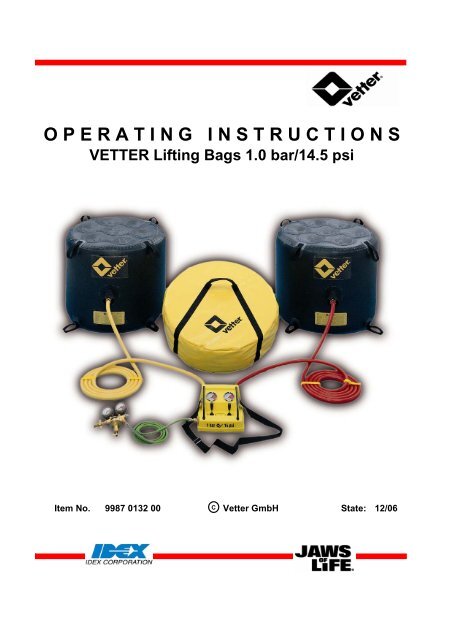
O P E R A T I N G I N S T R U C T I O N S<br />
VETTER Lifting Bags 1.0 bar/14.5 psi<br />
Item No. 9987 0132 00 C<br />
<strong>Vetter</strong> <strong>GmbH</strong> State: 12/06
<strong>Vetter</strong> Lifting Bags 1.0 bar/14.5 psi Page: 2<br />
Contents<br />
Preliminary remarks Page 3<br />
Safety information Page 3 - 4<br />
Correct use Page 5<br />
Inventory check Page 5<br />
Product description Page 6 - 9<br />
Preparations for use Page 10<br />
Instructions on use Page 10 - 11<br />
Operation with compressed air bottle Page 11 - 12<br />
Operation with other air supplies Page 13<br />
Additional accessories Page 14<br />
Elimination of defects Page 15<br />
Repetitive checks Page 15 - 16<br />
Care and storage Page 16<br />
Repair instructions Page 16 - 18<br />
Technical data for lifting bag Page 18<br />
1.0 bar/14.5 psi<br />
Technical date for pressure bags Page 19<br />
1.0 bar/14.5 psi<br />
Manufacturer information Page 19<br />
Declaration of conformity Page 20<br />
Test procedure Page 21 - 25<br />
List of dangers Page 26
<strong>Vetter</strong> Lifting Bags 1.0 bar/14.5 psi Page: 3<br />
Preliminary remarks<br />
Only knowledge and the exact observance of this operating manual<br />
guarantee correct and reliable operation, achieve the best possible<br />
usage and ensure any claims made within the framework of the <strong>Vetter</strong><br />
guarantee.<br />
Only a person who has been instructed in the use of <strong>Vetter</strong> Lifting Bags,<br />
using the manufacturer operating manual and the instructions from the<br />
user, is to be given the operation task.<br />
Safety information<br />
The prespecified protective clothing is to be worn during the operation.<br />
National regulations connected with the lifting bag systems and their<br />
operation are to be observed.<br />
Lifting bags are only to be used with compressed air.<br />
Under no conditions are inflammable or aggressively acting gases to be<br />
used.<br />
The lifting bags must only be inflated with original <strong>Vetter</strong> fittings because<br />
these are subjected to an acceptance test by the manufacturer.<br />
The lifting bag system is to be checked before and after operation to<br />
determine whether it is in perfect condition.<br />
Never lay two or more lifting bags<br />
on top of each other.<br />
Ensure that the load does not slip.<br />
Gravitationally support loads being lifted during a continuous lifting<br />
procedure.<br />
Always pay particular attention to the stable condition of the support<br />
material during support work.<br />
The support structure must at least support<br />
the whole area of the bag and must be larger<br />
in its length and width than in its height!
<strong>Vetter</strong> Lifting Bags 1.0 bar/14.5 psi Page: 4<br />
Attention danger of slipping !<br />
Never place metal on metal<br />
when carrying out support work<br />
Place stones, branches or similar items under the bag in order to<br />
increase ground grip when the ground is slippery (ice, snow, mud etc.).<br />
Avoid pointed loads such as grips, screws etc.<br />
Never place the bags on sharp edges or hot to red hot components.<br />
Use suitable intermediate layers and cover the whole bearing area of<br />
the bag.<br />
Protect the bag from sparks from welding or separation work.<br />
Do not additionally subject the bag to such things as hydraulic stamps,<br />
hoists, falling loads etc.<br />
Never remain under the load being lifted,<br />
and never try to grip the load from below !<br />
Remain at a safe distance !<br />
Avoid shearing effects caused by bag squeezing when deflating.<br />
Never stand in front of the load during operation, always place yourself<br />
to the side of it, because the bag can be catapulted out under<br />
unfavourable conditions.
<strong>Vetter</strong> Lifting Bags 1.0 bar/14.5 psi Page: 5<br />
Correct use<br />
Lifting bags are mainly pneumatically (usually with air) driven<br />
rescue equipment for the rescue services (e.g. fire service) with<br />
which trapped people can be freed, paths made to carry out<br />
rescue or counter-measures etc.<br />
The lifting bags can also be used as working equipment to lift or<br />
move objects.<br />
Lifting bags meet the requirements specified in DIN 14 152 T 1 as well<br />
as GUV-G 9102 in the field of fire services.<br />
Further operational instructions are specified in the operating manual<br />
of the user.<br />
Inventory check<br />
Items<br />
2 Lifting bags, of the same type and size<br />
2 Inflation hoses, 5 m (16.4 ft.) in length<br />
1 Dual deadman controller<br />
alternative:<br />
1 Dual controller in fitting design<br />
1 Pressure regulator 200/300 bar<br />
1 Packing bag<br />
1 Set repair material<br />
1 Operating instruction<br />
Other set combinations are possible if required !
<strong>Vetter</strong> Lifting Bags 1.0 bar/14.5 psi Page: 6<br />
Product description<br />
Due to the high pressure point load, it is frequently not possible<br />
to use winches or hydraulic lifting gear when dealing with heavy,<br />
unstable loads.<br />
In such cases the advantages of <strong>Vetter</strong> lifting bags become very much<br />
apparent:<br />
Very light<br />
Low pressure point loading<br />
Very flat in design<br />
Can be used in any position<br />
As already known, air distributes itself evenly<br />
on all sides.<br />
The ideal shape of a pressure container is<br />
spherical.<br />
With flexible pressure containers, such as the<br />
lifting bag, the top and bottom as well as sides<br />
bulge.<br />
With lifting bags this bulging, especially of the<br />
top and bottom, could damage the bag when<br />
pressed against sharp objects and the bag<br />
may become cut, punctured or abraded.<br />
Danger of damage to the<br />
pressurized walls of the bag.<br />
The VETTER construction<br />
Bags which have a cylinder shape cannot<br />
bulge on the side because the material tensions<br />
evenly.<br />
This characteristic greatly reduces any damage<br />
to the side wall.
<strong>Vetter</strong> Lifting Bags 1.0 bar/14.5 psi Page: 7<br />
Owing the extensive use of internal<br />
harnesses, bulging of the top and bottom is<br />
avoided.<br />
The strong, multi-layer and reinforced material<br />
avoids bag damage within the working area.<br />
The supporting material of the lifting bag is made of<br />
ARAMIDE<br />
which is a very light but tear-resistant artificial fibre.<br />
The coating of the supporting material is made of<br />
NEOPRENE<br />
which is a synthetic artificial rubber.<br />
As opposed to material rubber, NEOPRENE has ideal characteristics<br />
for the lifting bag, e.g.:<br />
High resistance to mineral oil and acid<br />
High resistance to wear and has a long life cycle<br />
Maintenance free<br />
The flexible lifting bags mould themselves to the shape of the load<br />
to be lifted as opposed to hydraulic and pneumatic lifting gear with<br />
their solid positioning plates. In connection with the very low application<br />
pressure of only 1.0 kg/cm², loads can be lifted carefully.<br />
Lifting bags, irrespective of the type, are unstable<br />
over the complete lifting distance !<br />
When using just one bag it must be positioned<br />
exactly under the load's centre of gravity<br />
otherwise load movement cannot be avoided.<br />
In practise, exact positioning<br />
is not possible !<br />
If the use of one bag cannot be avoided then positioning stability<br />
of the load is to be ensured.
<strong>Vetter</strong> Lifting Bags 1.0 bar/14.5 psi Page: 8<br />
However, if two bags are used and if one bag<br />
is placed to the front part and the other bag to<br />
the rear part of the load then the centre of<br />
gravity will always be between the two bags.<br />
The basic condition for a stable, different control of both bags is the<br />
separate independent control using the corresponding dual controller.<br />
Due to this, the Lifting Bags 0.5 bar and 1.0 bar<br />
are equipped with the following:<br />
2 Bags of the same type and size<br />
2 Inflation hoses 5 m and 10 m long<br />
1 Dual deadman controllers<br />
1.0 bar/14.5 psi<br />
1 Pressure regulator 200/300 bar<br />
(special version for US, F and J)<br />
The corresponding packing bag is included as well as 1 repair set.<br />
Lifting bags 1.0 bar/14.5 psi are subject to the requirements specified in<br />
DIN 14 152 T 1 (prEN 13 731).<br />
According to DIN, lifting bags are classified as PNEUMATIC LIFTING<br />
DEVICES with the following definitions:<br />
Pneumatic lifting devices according to<br />
DIN 14 152 T 1<br />
DIN- Side Min<br />
Description wall lift / kN<br />
LH 10 S Yes 10<br />
LH 20 S Yes 20<br />
LH 30 S Yes 30<br />
LH 50 S Yes 50<br />
LH 10 No 10<br />
LH 30 No 20
<strong>Vetter</strong> Lifting Bags 1.0 bar/14.5 psi Page: 9<br />
The following <strong>Vetter</strong> lifting bags correspond to the listed standard<br />
types:<br />
Standard <strong>Vetter</strong> Lifting Bags<br />
1.0 bar/14.5 psi<br />
LH 10 S 1/6<br />
LH 20 S 1/9<br />
LH 30 S 1/13<br />
LH 50 S 1/23<br />
Pneumatic lifting device or lifting bag without side wall can be supplied<br />
if required.<br />
As opposed to the national standard DIN 14 152 T 1, the European<br />
standard prEN 13 731 requires the following with a controller:<br />
5.2.4.6 When the operating device of a controller<br />
is released then it must immediately return<br />
to the "neutral " position automatically<br />
The so called "deadman switch" was introduced as a compulsory<br />
fitting to meet the requirements of this standard.<br />
Dual controller 1.0 bar with deadman<br />
switch.
<strong>Vetter</strong> Lifting Bags 1.0 bar/14.5 psi Page: 10<br />
Preparations for use<br />
Remove the set of lifting bags from the transport and unpack the packing<br />
bag.<br />
Make certain that the inflation device is ready for operation.<br />
Make certain that there is sufficient air supply available.<br />
Only perfectly working and tested lifting bag systems are to<br />
be used.<br />
The person in charge of the operation is to decide on the method<br />
and how it is to be applied from case to case within the field of his<br />
responsibility as well as observance of the operating instructions of<br />
the user.<br />
Instructions on use<br />
Move the lifting bag to a suitable position so that at least 75%<br />
of the supporting bag surface is under the load.<br />
Normally at least two bags are used of the same type and<br />
size. Position each bag near to the end of the load. If necessary<br />
use lines for drawing under the load or lower between loads<br />
which have to be pressed apart.<br />
Depending on the low operation pressure of the<br />
lifting bags, the maximum pressure point loading is<br />
only:<br />
1,0 kg/cm² with lifting bags 1.0 bar<br />
Due to low bearing pressure, under-support for ground fixture is only<br />
necessary in exceptional cases.<br />
The load to be lifted is to be<br />
secured against slipping by<br />
suitable measures !
<strong>Vetter</strong> Lifting Bags 1.0 bar/14.5 psi Page: 11<br />
Before moving the lifting bag under the load it should be ensured<br />
that the side wall material is positioned between the top and bottom plates.<br />
Under no circumstances should the side wall material be between the<br />
load and top or the load and bottom during the lifting sequence. This can,<br />
under certain circumstances, cause damage to the side wall of the bag.<br />
If the movement height or the movement area is not sufficient for<br />
correct application of the lifting bag, then the required space can normally<br />
be quickly obtained by using the <strong>Vetter</strong> Mini Lifting Bag 8 bar.<br />
Operation with compressed air bottle 200 bar or 300 bar<br />
Connect the pressure reducer to the compressed<br />
air bottle, 200 bar or 300 bar, using the tommy<br />
screw (1).<br />
Close the presser reducer (2).<br />
Open the valve on the bottle (3).<br />
The pre-pressure manometer (4) indicates the<br />
pressure in the bottle.<br />
Adjust the back pressure to approximately 2 bar with the regulation bar (5)<br />
(indication of the reduced pressure on the back pressure manometer (6)).<br />
7<br />
3<br />
4 6<br />
1<br />
8<br />
5<br />
2<br />
9<br />
Open the handwheel (3) of the pressure reducer.<br />
The lifting bag system is ready for operation.<br />
Connect the air hose of the pressure reducer via<br />
the nipple to the input coupling (7) of the<br />
controller. In doing this, press the nipple into<br />
the coupling until you feel it lock in.<br />
For additional safety: turn the brass sleeve (8)<br />
so that it is opposite the safety pin (9).<br />
11 To inflate the lifting bag<br />
pull the lever (9) back,<br />
resp. slowly open the<br />
11<br />
9<br />
ball valve (10).<br />
Observe the manometers<br />
(11) and the load.<br />
10
<strong>Vetter</strong> Lifting Bags 1.0 bar/14.5 psi Page: 12<br />
If the required pressure is reached for lifting or if the lift height is<br />
achieved, then end the inflation sequence by releasing the switch<br />
lever or close the ball valve.<br />
The switch lever of the controller with the deadman switch will<br />
automatically go back to the zero position.<br />
An integrated safety valve will automatically activate when the bag<br />
is unintentionally over-inflated above the maximum operating pressure<br />
(1.0 bar/14.5 psi) or when there is an increase in bag pressure due to<br />
additional loading of the bag.<br />
The activation tolerance for opening and closing of the safety valve<br />
must not exceed +/- 10%.<br />
Press the switch lever to "Deflate" in order to deflate the bag or to<br />
lower the load, resp. open the head of the safety valve (counter-clockwise)<br />
when using the fitting controller.<br />
Load behaviour and lift movement must always be continuously<br />
monitored.<br />
Depending on the type, position and behaviour of the load during the<br />
lifting sequence, the lifting bags are either<br />
simultaneously and evenly inflated or<br />
inflated step-by-step, resp. individually.<br />
Remember to remain at a safe distance from the load !<br />
Do not stand directly in front of the lifting bags<br />
because if the positioning is incorrect the bags<br />
could be catapulted outwards.<br />
Never leave the controller and the inflation device unattended while<br />
the lifting bags are under pressure.<br />
Never disconnect the connection between bags and controller while<br />
the bags are under pressure.
<strong>Vetter</strong> Lifting Bags 1.0 bar/14.5 psi Page: 13<br />
Operation with other air supplies<br />
The set of transition pieces (Order No. 1600 0125 00) with the<br />
following adapters is available for operation with other air supplies:<br />
1 ) Truck compressed air connection, 2-way brake system.<br />
For extracting air from the trailer coupling head.<br />
2.) Blind coupling<br />
Closes the control line of the brake system.<br />
Remember !<br />
Ensure the truck does not roll away by using brake blocks !<br />
3.) Truck tyre inflation device adapter<br />
For extracting air from the tyre inflation bottle in the area of the<br />
braking device.<br />
Remember !<br />
As a standard, the tyre inflation connection must be protected<br />
by a safety valve (blow-off pressure: approx. 7.5 bar/108.8 psi) !<br />
4.) Truck tyre valve<br />
For inflation with a normal hand or foot pump as well as any<br />
other air source for the inflation of tyres.<br />
5.) Truck tyre valve connection, can be clamped.<br />
For air extraction from the spare tyre.<br />
6) Adapter for the permanent compressed air supply at the location.<br />
7) Air supply hose, 10 m (32 ft.) long, green<br />
8) Air supply hose, 10 m (32 ft.) long, green, with shut-off valve<br />
9) Bag, red<br />
9<br />
7<br />
8<br />
2 1 5 4 3<br />
6
<strong>Vetter</strong> Lifting Bags 1.0 bar/14.5 psi Page: 14<br />
Additional accessories<br />
7<br />
8<br />
10<br />
11<br />
12<br />
9<br />
5<br />
6<br />
Pos. Item no. Description<br />
1600 0105 00 Comp. air bottle 10 l / 200 bar<br />
1600 0091 00 Comp. air bottle 6 l / 300 bar<br />
1600 0103 00 Comp. air bottle 4 l / 200 bar<br />
1600 0101 00 Comp. air bottle 1 l / 200 bar<br />
5 1600 0084 00 Dual connector 200 bar<br />
6 1600 0091 00 Dual connector 300 bar<br />
7 1600 0116 00 Safety and carrying frame<br />
(without bottles)<br />
8 1600 0118 00 Wheel trolley for safety and<br />
carrying frame<br />
(Fig. with 2 x Pos. 7)<br />
(without bottles)<br />
9 1600 0087 00 Hand pump<br />
10 1600 0094 00 Foot pump<br />
11 1600 0145 00 Pressure regulator<br />
12 1600 0120 00 Adapter for compressor
<strong>Vetter</strong> Lifting Bags 1.0 bar/14.5 psi Page: 15<br />
Elimination of defects<br />
If a safety valve blows-off too early because a foreign body has<br />
penetrated and is lodged in, then the blow-off device is to be opened at<br />
the head of the safety valve by turning counter-clockwise so that<br />
the compressed air is able to escape.<br />
If the foreign body is not removed, then the upper part of the valve<br />
must be unscrewed with the safety valve disassembled. To do this<br />
position the tube pliers in the centre and unscrew by turning to the left.<br />
Carefully remove the valve ball and remove the foreign body.<br />
Screw the upper part of the valve tightly back and assemble the safety<br />
valve, and check to make certain that it functions perfectly.<br />
The set pressure must not be changed.<br />
If the seal or seal plate has been removed on the upper<br />
part of the valve then reliable function is not guaranteed.<br />
The safety valve is to be exchanged.<br />
If there are functional defects on the pressure reducer or controller<br />
due to icing, high humidity at low temperatures, then use a normal<br />
defrosting agent (similar to that used on cars).<br />
Repetitive checks<br />
Repetitive checks are to be made on lifting bag systems as follows:<br />
A) Testing during acceptance<br />
Check to ensure that all items are present and complete; this is<br />
made by the person commissioned for the task.<br />
A visual and function test is to be made by an instructed person<br />
according to the operating instructions.<br />
B) A visual and function test is to be made after each period of use /<br />
application and carried out by an instructed person.<br />
This test is to be documented.<br />
C) The lifting bag system is to undergo a visual test and function<br />
test at least once each year by a trained person and is to be made<br />
according to the check list in the following pages.<br />
This test is to be documented.
<strong>Vetter</strong> Lifting Bags 1.0 bar/14.5 psi Page: 16<br />
D) Every 5 years, or if there is any doubt about the safety or<br />
reliability, the lifting bag is to be tested according to GUV-G 9102<br />
(formally GUV 67.13) by the manufacturer.<br />
The responsibility for the correct and professional execution of the<br />
repetitive test lies with the user !<br />
Lifting bags or lifting bag systems are not subject to the requirements<br />
specified in EC Guidelines 97/123/EC (refer to Section 3.15).<br />
A repetitive test by a specialist (e.g. TÜV or DEKRA) is no longer<br />
necessary.<br />
Care and storage<br />
The lifting bag equipment is to be cleaned each time after use.<br />
Normally cleaning is made with warm water and a soap detergent.<br />
A chemical cleaning agent is not to be used under any<br />
circumstances and high pressure warm water equipment<br />
is also never to be used.<br />
Drying is made at room temperature.<br />
DIN 7716 is to be observed with any long storage periods.<br />
Repair instructions<br />
Small cracks or cuts in the side wall material (max. 4 cm) can be<br />
quickly repaired without difficulty using the supplied repair material.<br />
The repair must only be made with the <strong>Vetter</strong> Repair Set<br />
(Item No. 0100 0010 00).<br />
4<br />
3<br />
1<br />
5<br />
2<br />
The repair set consists of:<br />
1 Patches 100 mm diameter<br />
1700 0177 00<br />
2 Patches 120 mm diameter<br />
1700 0178 00<br />
3 Special adhesive<br />
1700 0010 00<br />
4 Emery paper<br />
1700 0009 00<br />
5 Bag<br />
1700 0008 00
<strong>Vetter</strong> Lifting Bags 1.0 bar/14.5 psi Page: 17<br />
max.<br />
4 cm<br />
If other patch material is used, e.g. hose patches or other<br />
types of adhesive bonding (vulcanization), then this<br />
could cause damage to the material.<br />
Danger of bursting !<br />
The patch material is intended for the<br />
repair of damaged positions (cracks etc.)<br />
up to a length of 4 cm.<br />
12 Any larger damage must be repaired by the<br />
cm manufacturer.<br />
Clearly mark the position of the patch<br />
on the damaged bag material.<br />
Roughen the marked area evenly with<br />
sand paper.<br />
Too much force causes the rubber to<br />
be worn which will in turn cause damage<br />
to the webbing structure.<br />
Roughen one side of the patch.<br />
Clean the roughened surfaces thoroughly<br />
of any dust or other dirt.<br />
Using a brush, apply the special adhesive<br />
to the roughened marked area and also<br />
to the patch.<br />
Let the adhesive dry for approximately<br />
20 Minutes so that it is dry to touch.
<strong>Vetter</strong> Lifting Bags 1.0 bar/14.5 psi Page: 18<br />
Place the patch over the damage area<br />
marked, and using a blunt instrument<br />
rub the complete area of the patch using<br />
a high amount of pressure.<br />
After this, allow a drying period of 24 to<br />
48 hours.<br />
The repaired lifting bag is to be given a visual check as well as a function<br />
check, especially for sealing, by a specialist person before putting into<br />
operation.<br />
It is imperative that larger areas of damage be repaired by the manufacture.<br />
Contact the manufacturer if there are any questions or if there is any<br />
doubt concerning the correctness or reliability of the repair.<br />
Technical data for lifting bag 1.0 bar/14.5 psi<br />
Typ 1/23 1/13 1/9 1/6<br />
DIN Nomination LH 50 S LH 30 S LH 20 S LH 10 S<br />
Lifting power cm/inch 11.3/12.45 6.5/7.15 4.5/4.95 3.0/3.3<br />
Lifting power set cm/inch 22.6/24.9 13.0/14.3 9.0/9.9 6.0/6.6<br />
Lifting height, max. cm/inch 110/43 62/24 60/24 45/18<br />
Insertion height cm/inch 3/1.2 3/1.2 3/1.2 3/1.2<br />
(uninflated)<br />
Diameter cm/inch 120/47 91/36 76/30 61/24<br />
Working pressure bar/psi 1.0/14.5 1.0/14.5 1.0/14.5 1.0/14.5<br />
Test pressure bar/psi 1.5/21.75 1.5/21.75 1.5/21.75 1.5/21.75<br />
Air requirement at 1.0 bar l/cu.ft. 2,486/88 806/28 544/19 262/9<br />
Nominal content l/cu.ft. 1,243/44 403/14 272/9.6 131/4.6<br />
Inflation time, approx. sec. 191 62 42 20<br />
Weight, approx. kg/lbs 21/46 12/26 9/20 7/15<br />
Weight (set), approx. kg/lbs 58/128 40/88 32/71 25/55
<strong>Vetter</strong> Lifting Bags 1.0 bar/14.5 psi Page: 19<br />
Technical data for pressure bags 1.0 bar/14.5 psi<br />
Typ LH 1/10 LH 1/30 LH 1/10 S LH 1/20 S LH 1/30 S LH 1/50 S Rescue Set<br />
Lifting power cm/inch 2.1/2.3 6.2/6.8 2.2/2.4 4.5/4.9 6.1/6.7 7.1/7.8 12.1/13.3<br />
Lifting height cm/inch 21/8 43/17 37/15 65/26 65/26 75/30 65/26<br />
Insertion height cm 2 2 4 4 4 4<br />
(deflated) inch 0.8 0.8 1.6 1.6 1.6 1.6<br />
Size cm 65 x 32 65 x 95 50 x 45 70 x 65 90 x 71 90 x 80<br />
inch 26 x 13 26 x 37 20 x 18 28 x 26 35 x 28 35 x 32<br />
Working bar 1.0 1.0 1.0 1.0 1.0 1.0 1.0<br />
pressure psi 14.5 14.5 14.5 14.5 14.5 14.5 14.5<br />
Test pressure bar 1.5 1.5 1.5 1.5 1.5 1.5 1.5<br />
psi 21.75 21.75 21.75 21.75 21.75 21.75 21.75<br />
Air requirement l 52 228 248 760 1,082 1,434 2,164<br />
at 1.0 bar cu.ft. 1.84 8.05 8.75 26.83 38.19 50.62 76.39<br />
Nominal content l 26 114 124 380 541 717 1,082<br />
cu.ft. 0.92 4.02 4.38 13.41 19.10 25.31 38.19<br />
Packaged size cm 110 x 72 x 30<br />
inch 43 x 28 x 12<br />
Inflation time sec. 4 18 19 58 83 110 164<br />
Weight, approx. kg/lbs 2.5/5.5 6.0/13.2 3.1/6.8 5.5/12.1 7.0/15.4 11.0/24.3 25.0/55.1<br />
All rights are reserved for any improvements within the<br />
scope of product improvement.<br />
<strong>Vetter</strong> <strong>GmbH</strong><br />
A Unit of IDEX Corporation<br />
Blatzheimer Str. 10-12<br />
D-53909 Zülpich<br />
Tel.: +49 (0) 2252-3008-60<br />
FAX: +49 (0) 2252-3008-71<br />
info@vetter.de
<strong>Vetter</strong> Lifting Bags 1.0 bar/14.5 psi Page: 20<br />
EC Declaration of Conformity<br />
in terms of the EC Machine Directive<br />
We,<br />
<strong>Vetter</strong> <strong>GmbH</strong><br />
A Unit of IDEX Corporation<br />
Blatzheimer Strasse 10-12<br />
D-53909 Zülpich<br />
hereby declare that the VETTER Lifting Bags and Pressure Bags 1.0 bar/14.5 psi<br />
for lifting and lowering loads<br />
Serial-No.:<br />
Design:<br />
(refer to equipment label, to be entered by the customer)<br />
complies with the following pertinent regulations in its standard design:<br />
Machine Directive 98/37/EG<br />
Harmonised standards employed:<br />
EN 292 Part 1/2<br />
according to prEN 13731<br />
National standards and technical specifications employed:<br />
DIN 14152<br />
according to the EC Directive 97/23 EC<br />
We hereby assure that the certification procedure was conducted in accordance with the<br />
Directive 98/37/EC of the European Parliament and of the Council of 22 June 1998 on the<br />
approximation of the laws of the Member States relating to machinery and that the requirements<br />
of the standard DIN EN 45 014 General Criteria for Supplier's Declaration of Conformity were<br />
observed in the preparation of the Declaration of Conformity.<br />
Zülpich, 14.11.2006
<strong>Vetter</strong> Lifting Bags 1.0 bar/14.5 psi Page: 21<br />
Test procedure for VETTER Lifting Bags 1.0 bar/14.5 psi<br />
This test procedure only applies to the visual test and the function test carried out by a trained<br />
person. The pressure test of the bag, made after 5 and 10 years, is to be carried out by the<br />
manufacturer according to DIN 14 152 T 1.<br />
This test procedure was created according to state of the art technology known to us and<br />
according to statutory regulations.<br />
Should these regulations have changed, then the person carrying out the test is obliged to<br />
carry out the test according to the regulations and standards valid on the day of the test.<br />
Contact the manufacturer if there is any doubt about this.<br />
Reason for test After operation Annual test<br />
Person carrying out the test (trained)<br />
Item being tested 1 Set <strong>Vetter</strong> Lifting Bags<br />
Type<br />
Serial number<br />
Nominal content of bag / litre<br />
Permissible operating pressure / bar<br />
Year of manufacture<br />
Date of last test<br />
Bag 1 Bag 2<br />
1. Item check Available Not available<br />
1.1 2 Bags<br />
1.2 1 Bag<br />
1.3 2 Inflation hoses<br />
1.4 1 Dual controller<br />
1.5 1 Pressure regulator<br />
1.6 1 Repair set<br />
1.7 1 Operating instructions<br />
1.8 1 Inspection book / file<br />
Remarks / Notes
<strong>Vetter</strong> Lifting Bags 1.0 bar/14.5 psi Page: 22<br />
2. Visual test<br />
2.1 Bag 1<br />
Firstly clean the bag with soapy water<br />
if it is dirty YES NO<br />
2.1.1 Bag free of damage after a visual check.<br />
2.1.2 Side wall material free of cuts, cracks,<br />
punctures, separations or other forms of damage,<br />
e.g. hardened areas, traces of acid etc.<br />
2.1.3 Top and bottom plates free of cuts, cracks,<br />
punctures, separations or other forms of damage,<br />
e.g. hardened areas, traces of acid etc.<br />
2.1.4 Adhesive seams and overlap areas free of damage<br />
or separations.<br />
2.1.5 Securing devices (loops) for rope are available.<br />
2.1.6 Inflation coupling with fixture free of recognizable damage.<br />
2.2 Bag 2<br />
2.2.1 Bag free of damage after a visual check.<br />
2.2.2 Side wall material free of cuts, cracks,<br />
punctures, separations or other forms of damage,<br />
e.g. hardened areas, traces of acid etc.<br />
2.2.3 Top and bottom plates free of cuts, cracks,<br />
punctures, separations or other forms of damage,<br />
e.g. hardened areas, traces of acid etc.<br />
2.2.4 Adhesive seams and overlap areas free of damage<br />
or separations.<br />
2.2.5 Securing devices (loops) for rope are available.<br />
2.2.6 Inflation coupling with fixture free of recognizable damage.<br />
2.3 Inflation hose<br />
2.3.1 Inflation hose free of cuts, cracks, punctures,<br />
buckles, separations or other forms of damage,<br />
e.g. hardened areas, traces of acid etc.<br />
2.3.2 Hoses free of hardened areas and free of any traces<br />
of thermal or chemical effects.<br />
2.3.3 Couplings are solidly fixed.<br />
2.3.4 Coupling screws are easy to move.<br />
2.3.5 Couplings not damaged.<br />
2.3.6 Sealings available and undamaged.<br />
2.3.7 Couplings can be connected to each other.
<strong>Vetter</strong> Lifting Bags 1.0 bar/14.5 psi Page: 23<br />
2.4 Dual controller F = Fitting design K = Deadman switch / Plastic housing<br />
2.4.1 Input coupling (plug in coupling) undamaged<br />
and operational<br />
2.4.2 Blocking valve (F) and control lever (K) free of<br />
external damage and easy to move<br />
2.4.3 Manometer protection cover (F) available<br />
2.4.4 Manometer with markings for the maximum<br />
operating pressure (1.0 bar/14.5 psi)<br />
2.4.5 Safety valves free of visual damage and each<br />
valve with a sealing<br />
2.4.6 Housing (K) free of visual damage<br />
2.4.7 Output coupling without visual damage<br />
and operational<br />
2.5 Pressure regulator<br />
2.5.1 Input sealing available<br />
2.5.2 Bottle connection thread undamaged<br />
2.5.3 Both manometers free of visual damage and have<br />
the marking of the maximum operating pressure<br />
2.5.4 Manometer protection cover is available<br />
2.5.5 Pressure adjustment lever is easy to move<br />
2.5.6 Blocking valve is undamaged and is easy to move<br />
2.5.7 Air hose is free of cracks, cuts, punctures,<br />
separations and other forms of damage,<br />
e.g. hardened areas, traces of acid etc.<br />
2.5.8 Connection nipple is undamaged<br />
2.5.9 Hose connection is secure<br />
2.6 Repair set<br />
2.6.1 Adhesive, patches, emery paper available<br />
2.6.2 The adhesive can still be used, not dried out<br />
If, at this point or at any time during the test, there should be any doubt<br />
regarding the safety aspect, then the test is to be interrupted and the bag<br />
as well as the equipment should be sent to the manufacturer.<br />
3. Function test<br />
Only when the visual test according to<br />
Point 2 and the equipment test do not<br />
produce any cause for rejection<br />
Connect pressure reducer to the compressed<br />
air bottle. Connect the blocking valve to the<br />
pressure reducer. Open the valve on the<br />
compressed air bottle.<br />
YES NO
<strong>Vetter</strong> Lifting Bags 1.0 bar/14.5 psi Page: 24<br />
3.1.1 Pre-pressure manometer indicates<br />
(pressure in the compressed air bottle)<br />
3.1.2 Back-pressure manometer indicates<br />
(if necessary increase the pressure using the adjustment lever)<br />
3.1.3 The pressure can be regulated over the whole<br />
adjustment range<br />
3.1.4 The safety valve remains sealed at the maximum<br />
pressure<br />
3.1.5 The blocking valve at the pressure reducer output<br />
is sealed when closed<br />
3.1.6 With a set pressure of 4 bar/58 psi, the pressure does not<br />
increase greatly within a period of 5 minutes<br />
Connect the pressure reducer to the controller using the air hose.<br />
Open the blocking valve of the pressure reducer.<br />
Adjust pressure to approximately 4 bar/58 psi.<br />
3.2 Air hose and input coupling are sealed<br />
YES NO<br />
Connect inflation hose to the dual controller. Alternately connect the hoses at the<br />
other end to the bayonet blind<br />
coupling (Item No.: 0350 0065 00).<br />
Adjust the pressure reducer to approx. 1 to 1.5 bar (14.5 to 21.75 psi).<br />
Slowly and carefully open the ball valve and the piston valve.<br />
3.3.1 Manometer on the controller indicates<br />
perfectly<br />
3.3.2 The safety valve fully opens at +/- 10%<br />
3.3.3 After the ball valve/piston valve has closed,<br />
the safety valve closes within the 10%<br />
tolerance<br />
Repeat the procedure at the other connection of the controller<br />
3.4.1 Manometer on the controller indicates<br />
perfectly<br />
3.4.2 The safety valve fully opens at +/- 10%<br />
3.4.3 After the ball valve/piston valve has closed,<br />
the safety valve closes within the 10%<br />
tolerance
<strong>Vetter</strong> Lifting Bags 1.0 bar/14.5 psi Page: 25<br />
Connect the lifting bag and inflate in the open up to approximately 0.1 bar<br />
3.5 After a repeat test, the bags are in perfect<br />
condition according to Sections 2.1 and 2.2<br />
Remain at a certain distance from<br />
people and buildings<br />
YES NO<br />
Increase the pressure in the bag to 50% of the maximum operating pressure.<br />
Remain at this pressure for 1 hour.<br />
3.6 Pressure drop must be less than 10% after 1 hour<br />
Increase the pressure to the maximum operating pressure<br />
3.7 There should be not bulges or other non-typical<br />
deformities<br />
Test results<br />
The test carried out produced<br />
the following results:<br />
The bag system is<br />
- correct and there are no doubts<br />
about safety for further application.<br />
- not correct<br />
---- the following is required:<br />
...................... .....................................<br />
Location / Date Signature / Person testing<br />
Next visual test and operational test<br />
Next pressure test by the manufacturer
<strong>Vetter</strong> Lifting Bags 1.0 bar/14.5 psi Page: 26<br />
List of dangers according to EN 292-1 and EN 292-2<br />
(also refer to Attachment A (normative) prEN 13731)<br />
Danger Page reference<br />
A.1 Mechanical dangers<br />
1.1 Danger of squeezing 3 / 4 / 7<br />
1.7 Danger of cutting or puncture 4 / 7<br />
1.9 Danger by catapulting out 3 / 4 / 7 / 8<br />
A.2 Danger from noise<br />
2.1 Damage to hearing 3<br />
2.2 Effects to speach 3<br />
A.3 Danger from materials<br />
3.1 Explosion 3<br />
A.4 Danger due to negligence<br />
ergonomic principles<br />
4.1 Unhealthy positioning 4<br />
4.2 Negligent use of personal 3<br />
safety devices<br />
4.3 Psychological stress 3<br />
4.4 Human error 3<br />
4.5 Wrong positioning of visual signs 5<br />
A.5 Unintended movements<br />
5.1 Failures/defective functions of control elements 9<br />
A.6 Mechanical failure<br />
6.1 Failure of energy supply 9 / 12<br />
6.2 Failure of control device 9 / 12<br />
6.3 Loss of stability 3 / 8<br />
A.7 Additional dangers<br />
7.3 due to control device 8 / 12<br />
7.5 Movement 3 / 12<br />
7.8 Non-permissible use 3 / 10<br />
7.9 Moving parts out of the hold position 3 / 7 / 8<br />
7.10 Missing or insufficient visual or acoustic<br />
warning devices 11<br />
7.11 Insufficient instructions for the user 3<br />
7.12 Falling loads 12<br />
7.13 Missing stability 7 / 8<br />
7.14 Strong uncontrolled movements 3 / 7 / 8<br />
7.15 Uncontrolled/unintended movement of load 3 / 7 / 8<br />
7.16 Insufficient holding devices 3 / 7 / 8<br />
7.17 Insufficient mechanical solidity of parts 3 / 7<br />
7.18 Exceptional conditions with assembly,<br />
testing, use, maintenance 3 / 8<br />
7.19 The effects of loads on people 3<br />
7.20 Danger due to negligence or ergonomic<br />
principles (impact of loads) 10 / 12<br />
7.21 Fire and explosion 3<br />
7.22 Control failure 3