
It's okay that not every old car out there is perfect. Scratch under the surface and there's bound to be some imperfection on all but the most concours-y of concours cars (and even some of those get to where they are by hiding their sins better than most). These are, after all, vehicles meant to be out on the road, and no matter how careful, age and use will take their toll. The seller of this 1975 Fiat X1/9 listed on Hemmings.com seems to know that full well, detailing both the good and bad of the highly modified and apparently thoroughly enjoyed two-seater. Nothing that'd keep it off the road, and it has been maintained since its restification 10 years ago, though there's plenty left to do to keep somebody busy. The good thing about having a punch list provided is that any buyers not only know exactly what they're in for, but can also get a head start on prioritizing and correcting those issues. From the seller's description:
This 1975 Fiat x1/9 is finished in yellow over beige custom bucket seats and black floor carpet with accent black trim and is powered by a mid-engine, 1.5-liter, inline-four paired with a four-speed manual transaxle. The car is an older restoration (2012) by the owner and features a Dellara wide-body kit, removable roof panel, custom headers and exhaust, popup headlights, Kenwood speakers in door panels (no radio), powder-coated luggage rack, and functional quarter-panel air intakes. Bed liner paint on engine cover and lower trim accents.
Engine and transaxle were replaced with 1.5 liter head, 35/75 A-411 cam, lightened flywheel and 3.76 R&P transaxle rebuilt by Midwest-Bayless. Bosch electric ignition and new ignition switch. Weber 32 DATRA 1/100 carburetor and Facet cube electric fuel pump with 74 micron and paper fuel filters and Revolution Electronics fuel pump controller.
Four-wheel independent suspension system with KYB Nitro Gas MacPherson struts. Drag 15-inch Extreme Alloys 15x7 40 GBM wheels with Adaptit USA wheel spacers to 4/100 bolt pattern supporting new Yokohama 205/50 R15 on rear and 195/50 R15 on front. During restoration new clutch, clutch plate, slave and master cylinders, Raybestos brake pads, rotors and calipers. New floor pans, rocker panels, carpet, custom bucket seats, and inner wheel well liners. Rack and pinion steering and tie rods replaced. Recored radiator, new coolant hoses, belts, reserve tank, etc. New exterior door handles. Original interior door panels, arm rests and handles. Oil changes and routine maintenance up-to-date. Some small tears on interior panels, carpet on driver’s side shows typical wear. Dashboard cracked, bezel on glovebox missing. Electronic gauges functional, some gauge lights missing, headlights rotate up and down, low and high beans functional. Turn signals not working. Some superficial rust underneath, small holes in front trunk floor, surface rust in trunk wells. Some nicks on the exterior, small crack on front spoiler, and small cracks on front, passenger-side fender. Otherwise exterior body and paint in good condition for a 12-year-old restoration. In 2020 replaced left and right rear wheel bearings, replaced fuel tank, new fuel sending unit, new starter. Car starts and runs well, shifts smoothly. The car has been driven about 12,000 miles since restoration (mileage at restoration 76,262, current 88,266). Awards: 2012 Second Place and 2015 First Place, Fiat Freakout National Meeting Class 1974-78 Fiat X1/9.


See more Fiats for sale on Hemmings.com.
Recent

Photo: Jeff Smith
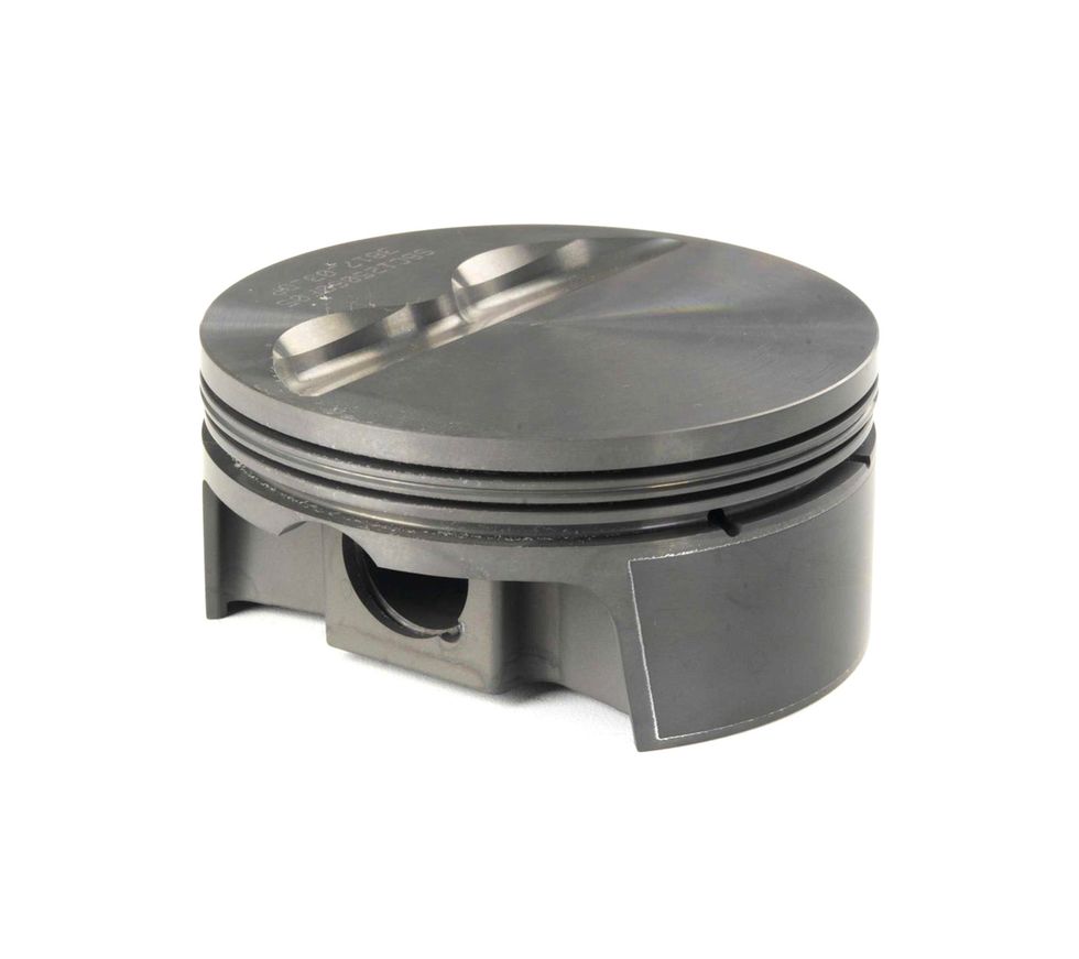 The piston top plays a vital role in determining compression on any engine. Dished pistons will add to the combustion chamber volume while domed pistons are intended to reduce overall volume and increase compression. The ideal combustion space combination is a flat piston top with a small chamber to improve combustion efficiency.Photo: Courtesy of Mahle Motorsports
Before we get into specifics, let’s first discuss how compression ratio is determined. In the old days before computers, engine builders had to run through the laborious task of determining the volume of each of the above variables. Bore and stroke for the cylinder is easy using the basic geometry of the volume of a cylinder which is the area of a circle (the bore) times the depth or length of the cylinder. The formula is from high school geometry: Pi x radius x radius x length. This is also the same formula you would use to calculate the volume of the piston above or below the deck as well as head gasket volume based on bore size and the thickness of the gasket.
The formula to compute the volume of the cylinder at the top of the stroke includes the piston top configuration (dish or dome), chamber size, head gasket thickness, and the distance the piston was either above or below the deck surface of the block. With regard to piston position, a piston that stopped its travel below the deck effectively adds this volume to the chamber size while a piston that travels above the deck would reduce that volume from the chamber.
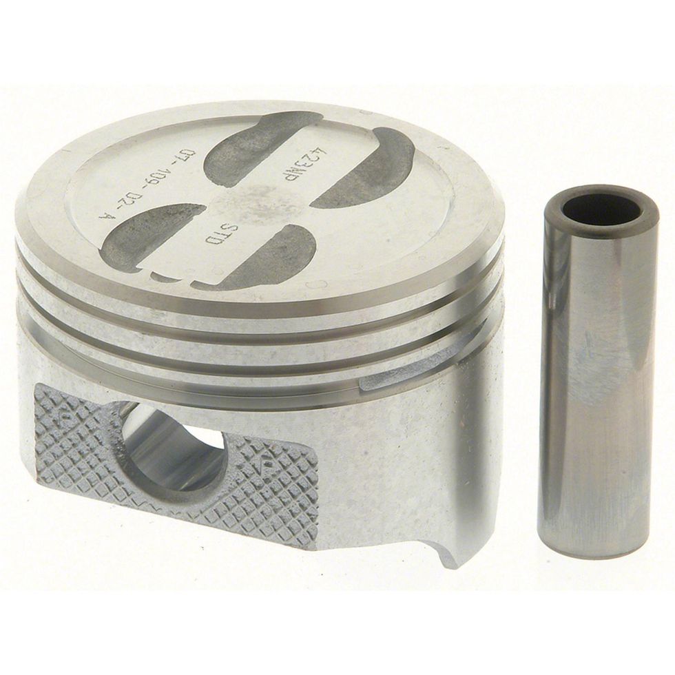 Even simple valve reliefs can affect compression. This standard four-eyebrow small-block Chevy replacement piston measures nearly 7cc’s worth of volume. Compare that to a pure flat-top, 6.0-liter Mahle piston with no reliefs. Of course, ensuring proper piston-to-valve clearance is important with either piston but the balance is always a compromise between adding compression yet avoiding bending valves when they hit the piston. Photo: Courtesy of Mahle Motorsports
We won’t get into the long-hand version of calculating compression only because it is both tedious and unnecessary now with the advent of online compression ratio computer programs. But it is important to understand the relationships between the components so that you can make decisions more effectively.
To assist in this process, you may need to convert combustion chamber volume that is usually measured in cubic centimeters (cc’s) into cubic inches or the opposite of cubic inches into cubic centimeters. We’ve listed these conversions in a separate chart to make finding them easy. As an example, a 70cc chamber converted to cubic inches would be 4.27 cubic inches.
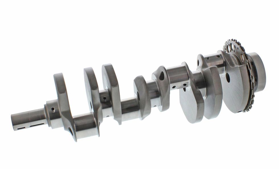 As mentioned in the story, crankshaft bore and stroke are significant contributors to compression or the lack of it. It is much easier to create compression with a longer stroke engine than one with a shorter stroke. This is a 4.00-inch stroke crank for an LS engine. Bolt this crank in with a 4.010-bore flat top piston with valve reliefs, a 70cc chamber and a near-zero deck and this will push compression up to over 10.6:1.Photo: Courtesy of Mahle Motorsports
Let’s start with the most basic item of bore size. An aspect that is not generally known is that increasing the bore size will also increase compression. As an example, let’s start with a 6.0L LS engine with a 4.00-inch bore, a 3.62-inch stroke, a 70cc combustion chamber, a pure flat top piston that is 0.005-inch below the deck surface and is using a 0.053-inch-thick head gasket.
Using Summit’s free online compression ratio calculator, the program gives us a compression ratio of 10.1:1. Now, if we increase the bore diameter to 4.030-inch, this increases the static compression ratio to 10.22:1.Then, if we change to a block with a larger 4.155-inch bore, our original 10.1:1 jumps to a more impressive 10.7:1 ratio.
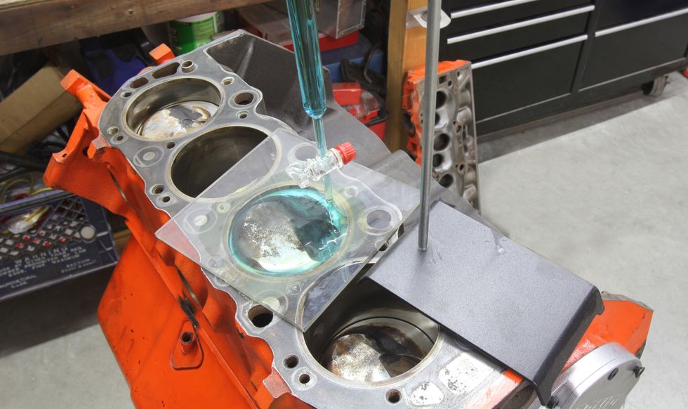
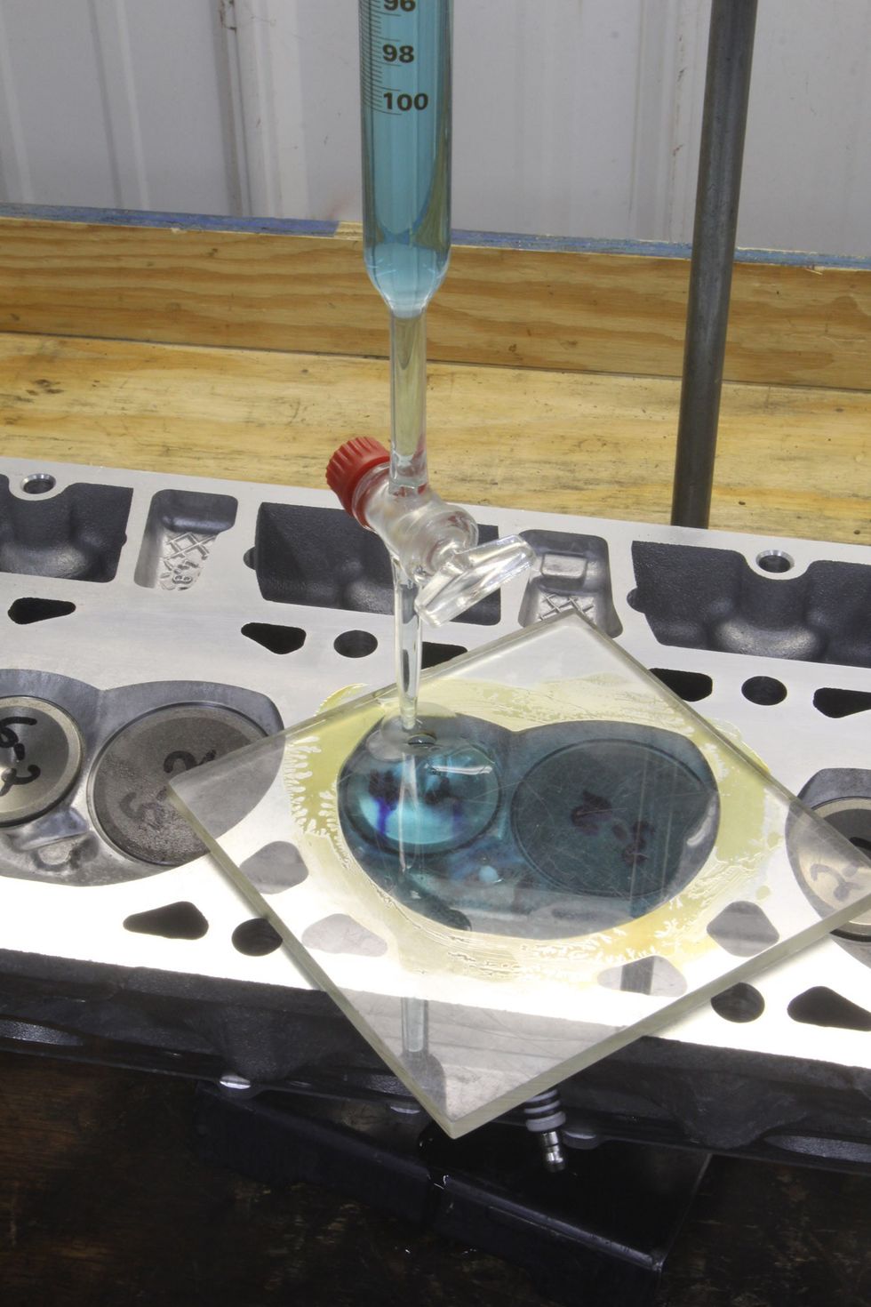 The best way to know the volume of any combustion chamber is to measure it with an affordable 100cc burette and a flat plexiglass plate. This is a simple procedure that produces very accurate results. Photo: Jeff Smith
Stroke has a much more dramatic effect on compression because of the substantial increase in volume that it creates. Let’s take our original 4.00-inch bore and 3.62-inch stroke LS engine stroke at 10.1:1 and add a 4.00-inch stroker crank to the mix. The original displacement was 364ci but now with a longer stroke, the cubic inches expand to a more impressive 402ci. On top of the displacement, this 0.380-inch increase in stroke drastically affects the compression pushing the original 10.1:1 now to 11.06:1.
The inverse is also true where a short stroke engine will have difficulty in creating static compression and is affected by small changes in chamber volume, gasket thickness, and piston top configuration. For this example, we’re going to go way back in time to a small 283ci displacement small-block Chevy to illustrate this point.
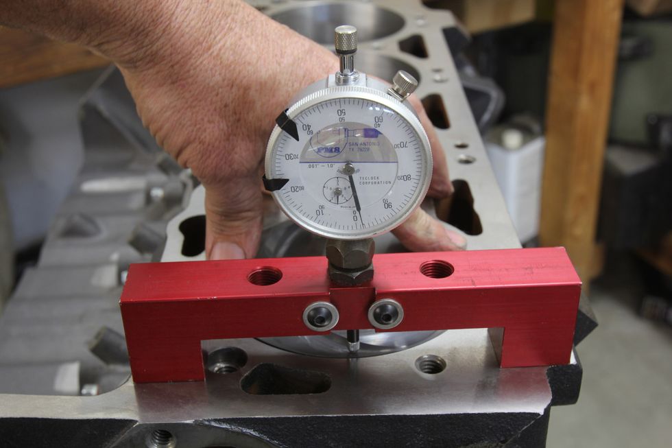 The position of the piston relative to the cylinder head deck is also critical. Most engine builders prefer to place the top of the piston at or near the deck surface, but you must also pay careful attention to piston-to-head clearance as well. A tight piston-to-head clearance for a typical wedge cylinder head engine might be 0.037-inch. Photo: Jeff Smith
The stock bore and stroke on a 283 is a combination of a 3.875-inch bore and a 3.00-inch stroke. With a 58cc combustion chamber, a flat top piston with four small (for a total of 8cc) valve reliefs, a 0.020-inch below deck height and a steel shim head gasket that is only 0.015-inch thick, the compression ratio for this engine comes out to 8.96:1. But often hot rodders will bolt a 64cc head on a 283 with bigger valves to try to make more power. What they don’t realize is that with a very short 3.00-inch stroke crank, a small chamber increase in size of 6cc has a big effect on compression. This change to a 64cc head will skewer the original compression ratio of 8.96:1 to 8.35:1 or a loss of over half a ratio!
But changes in chamber volume on a 4-inch stroke engine can be more dramatic even when the percentage of volume change is less than the smaller displacement engine. A change of 6cc in chamber volume on a 4-inch stroke, 4-inch bore engine while keeping all the other variables the same is worth a change of nearly three-quarters of a full point.
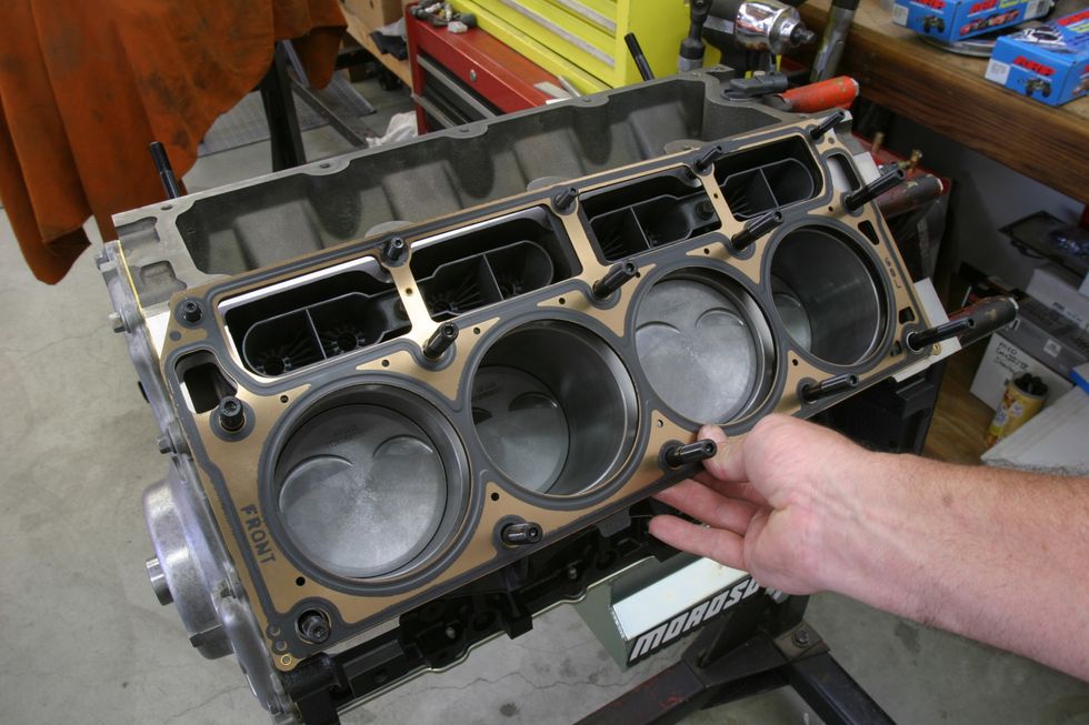 Another important variable is the compressed thickness of the head gasket. Many stock LS style MLS head gaskets can measure 0.053-inch and more. If you use one of these gaskets with a piston 0.020-inch below the deck surface, the compression ratio will suffer horribly so it’s always best to check before ordering gaskets.Photo: Jeff Smith
The numbers don’t lie. With a 4.010-inch bore, a 4.00 inch stroke, 70cc chamber, 0.051 gasket, a pure flat top piston, and a piston 0.005-inch below the deck computes out to 11.15:1, but add 6cc with a larger chamber and the compression drops to 10.45:1 or a drop of 0.70:1 in the ratio. These examples offer clues as to how easy it is to generate compression by simple changes.
Even the smallest details can offer advantages if you pay attention to their effects. As an example, piston design is a place where the smart engine builder can take advantage of his choice of piston top configurations. Most engine builders will agree that a small combustion chamber and a flat top piston with small valve reliefs are among the best ways to not only increase compression but also optimize combustion efficiency.
 If you are working on an engine with unknown components, you can position the piston a known distance down from the deck and use a 100cc burette to measure the volume of that cylinder. Then compute the volume of a theoretical cylinder with no valve reliefs, dish, or dome. Comparing the theoretical volume with the measured one will produce an accurate description of the piston in question. In this particular case, we established an accurate measurement of the effective dome volume of this piston.Photo: Jeff Smith
The GM LS family of engines is a classic example. Even the original LQ4 6.0 liter LS truck engine from the early 2000’s offered a 7cc dished piston combined with an intermediate sized 71cc combustion chamber to create a 9.5:1 compression ratio to run on 87 octane. A simple trick to enhance power is to add a pair of 5.3L LM4/LM7 heads with smaller 61cc chambers to bump the compression and gain some near free horsepower and torque.
Our calculations reveal a 61cc chamber will push the compression a full point from 9.3:1 to 10.3:1. Even though the 5.3L heads employ smaller intake valves, the increase in compression more than compensates and overall drivability is improved with more torque and horsepower.
Besides the large component options like pistons and combustion chambers, it’s best not to overlook the smaller yet significant details like head gasket thickness and piston deck height. For most engine builders, these two measurements are linked to help establish piston-to-head clearance.
We won’t get into too many details because the options are near limitless. But generally speaking a piston-to-head clearance for a street engine should be established around 0.040-inch or slightly tighter. This is important because sufficient clearance is necessary to prevent piston rock from angling the piston and hitting the combustion chamber.
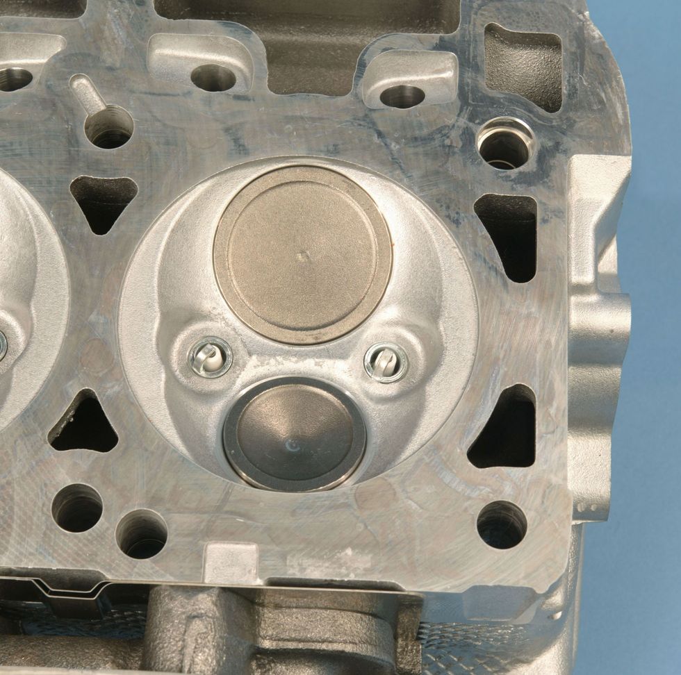 The modern Gen III hemi head is a hemispherical head in name only. Note that the chamber ends on opposite sides with flat or quench areas. These quench areas help with mixture motion as the piston nears top dead center (TDC) and improves combustion efficiency. Note that all Gen III Hemi engines use two spark plugs per cylinder to compensate for the long distance the flame front would otherwise travel to complete the combustion process. Both plugs fire at the same time and thus help improve both power and fuel mileage. A single spark plug in a Gen III Hemi would require a significantly increased ignition timing to approach the power made by using two plugs per cylinder. Photo: Jeff Smith
For wedge combustion chamber engines, this also establishes a tight quench area which is defined as the area between the flat areas of the chamber and the piston. As the piston arrives at TDC the tight clearance between the head and piston pushes (or squishes) the air and fuel into the chamber. This creates turbulence in the chamber and helps to stir the air and fuel into a more homogenous mixture that will combust more efficiently.
This means if you have an engine like an older small-block Chevy where the piston is buried deep in the cylinder to perhaps 0.025-inch, a thinner head gasket can be used to maintain the piston-to-head clearance at around 0.040-inch or less. One example of this would be the coated thin steel head gasket from Fel-Pro that measures only 0.015-inch (PN 1094) for a 350ci small-block Chevy. This will improve compression compared to a much thicker composition head gasket.
We’ve covered quite a bit of ground regarding compression ratio in hopes of offering some solutions or opportunities that you can take advantage of when building your next engine. It’s often the little details that can make all the difference.
Conversions
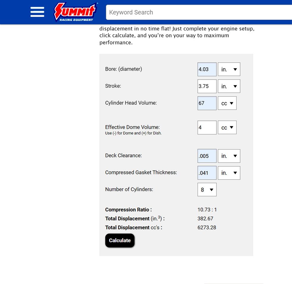
There are several free, online compression ratio programs to choose from. This one is from Summit Racing that you can find by searching Summit compression ratio program. These programs allow you to experiment with different chamber, gasket, and piston volumes to come up with the best overall compression ratio for your engine.
Photo: Courtesy of Summit Racing
- To convert cubic inches to cubic centimeters, multiply by 16.3871
- To convert cubic centimeters to cubic inches, multiply by 0.0610
Scaling Back The Squeeze
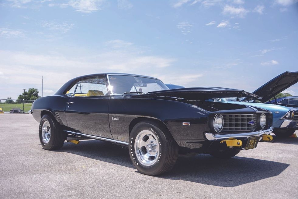
Some of the hottest muscle cars of the era, like this 427-powered COPO Camaro, had compression ratios of 11:1 or even greater.
Photo: Tommy Lee Byrd
Many muscle car engines from the late 1960s and early 1970s benefitted from compression ratios that were as high as 11:1. With today’s watered-down 91 and occasional 93 octane premium fuel, this often isn’t sufficient to prevent those older engines from detonating. Sure, you can mix in a little octane booster or race gas, but that’s expensive.
With today’s fuel, most sources will suggest no more than 9.0:1 for a compression ratio with iron heads. Our experience indicates you can run closer to 10:1 if the piston-to-head clearance is tight and the heads offer a decent, more modern chamber – like the newer LS engines, for example. Older engines with poor chambers tend to rattle with more than 10:1 to 10.5:1. Camshaft timing also has an effect on performance with bigger cams demanding more static compression compared to a street engine with milder cam timing. These engines are run more favorably with less compression. Of course, the more compression, the more power the engine will make with better efficiency so it’s a critical point.
It’s also possible to slow down the ignition curve and reduce timing, but these tend to make the engine run sluggish and unresponsive, which is not fun to drive. While you could rebuild the engine with a lower compression ratio with different pistons or cylinder heads, there are other alternatives.
Let’s take an example and show how we could reduce the static compression ratio on an original 350-cu.in. LT1 small-block Chevy without changing pistons or using different cylinder heads with larger combustion chambers.
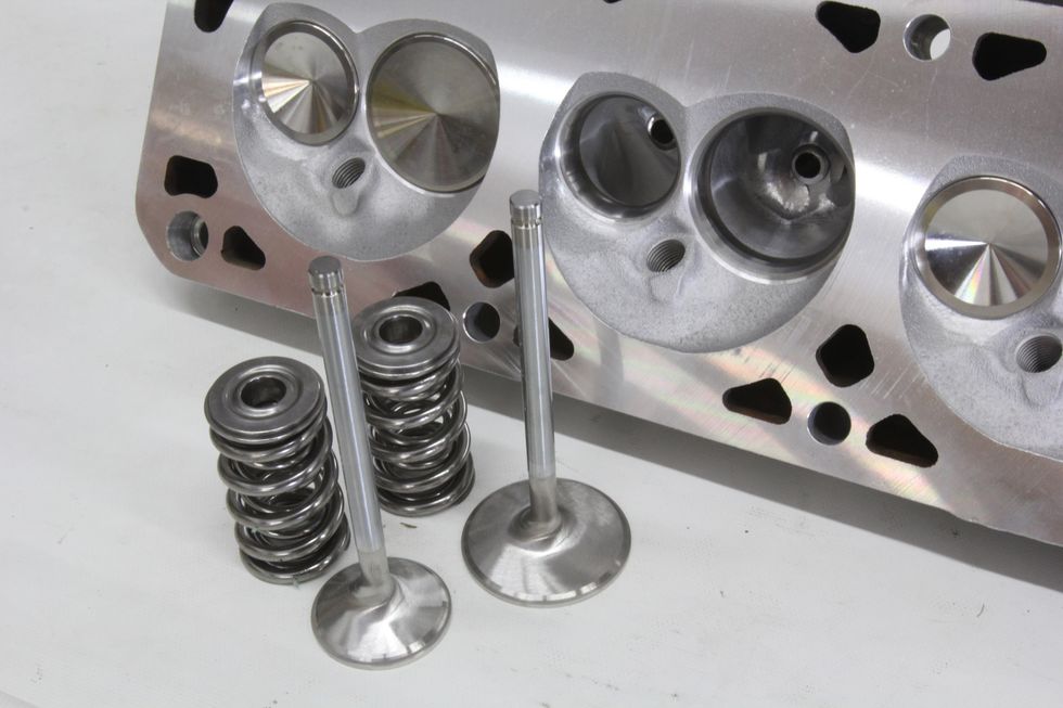
This is a pocket ported 5.3-liter cylinder head from our friends at West Coast Racing Cylinder Heads. Bolting on this smaller 61cc chamber head on a 6.0-liter engine is worth more than one full point in compression. The rule of thumb is one full point of compression is worth roughly 4 percent power, which on a 500 horsepower engine would be worth an additional 20 hp!
Photo: Jeff Smith
We simulated a 1970 LT1 using Summit Racing’s online compression ratio program. We came up with a 4.00-inch bore, 3.48-inch stroke, a 64cc chamber and a piston with a roughly 2cc dome (it’s really bigger but once the valve reliefs are subtracted from the dome volume, the net volume change is roughly 2 cc’s), with the piston 0.025-inch below the deck running a 0.020-inch head gasket. This combination creates a compression ratio of 11.2:1. Often back in those days the compression ratio was often lower than the specs due to production tolerances, but we’ll use these numbers.
One way to reduce compression would be to add a thicker, composition style head gasket. For example, merely replacing the stock shim gasket with a Fel-Pro 0.041-inch composition version will drop the static compression ratio down from 11.2:1 to 10.58:1. This will help but there are repercussions with this approach. This move changes the piston-to-head clearance from roughly 0.045-inch to a much wider 0.066-inch. This reduces the quench effect and might create a situation where this makes the engine more detonation sensitive. This is something to consider before choosing this approach.
A more time-consuming idea would be to increase the combustion chamber volume through grinding the iron chambers. With the addition of 4 cc’s to the chamber volume with the same thin had gasket, it’s possible to cut the compression to 10.64:1. This approach will require some knowledge and skill with a grinder, but it is possible. Of course, using a 68cc aftermarket head will be much better as these more modern heads offer far better chamber designs that can enhance power while often not requiring as much ignition timing.
It’s also possible to add dished intake and exhaust valves that will add one or two cc’s worth of volume with a recessed valve face that might add a slight amount of volume to the chamber. This also reduces the valve weight, which is another positive approach.
These are a few of the better ideas for altering compression for earlier high compression engines. If you have a late ‘70s engine, it will have the exact opposite issue of desperately needing compression with a boost of more than one full point just to get the engine back up somewhere close to 9:1. The best bet with these engines is to just swap to smaller chamber heads. Going from a 76cc chamber to 64cc chamber will pump the compression a full point on a typical 350-cu.in. small-block Chevy.

For car enthusiasts who weren’t around in 1975, you might hear a variation of “look around, what is happening in today’s world is what happened back then.” There is a vein of truth to that. Just a few years ago, buying a car with over 700 horsepower and a warranty that was brightly colored and sounded like the devil’s personal limousine was only a matter of having enough money to cover the purchasing cost. Two-door, four-door, station wagon, sports car, all available. But sooner or later, the party ends and now we have companies trying to foist electric vehicles and small crossovers that they promise will excite in the same way. The sad truth is, they won’t. Something is lost. The “x-factor”.

When the original era of muscle cars ended in the first half of the 1970s, it was the same scene. The only difference was that instead of technologically loaded vehicles, luxury was the by-word. Since you couldn’t feel the grunt of torque like you used to, you might as well feel sumptuous seats, leather-covered surfaces, and a ride that was numb to the road. Surprisingly, this sold well. Chevrolet took inspiration from Pontiac’s Grand Prix for their Monte Carlo and pretty much everyone followed suit. As the pony cars died off one-by-one, they were replaced with a new style: the personal luxury car. Those nameplates that remained evolved into softer, plusher and larger versions of themselves.

The Dodge Charger was no exception. While there were signs of luxury creeping in after the 1971 B-body debuted, the overall shape of the car still meant business, especially on NASCAR circuits where Richard Petty continued his reign as the king. But for 1975, Chrysler Corporation had a problem: they could either chase the Monte Carlo’s path to personal luxury sales, or they could carry over the 1974 body and satisfy enthusiasts but miss the potential sales. Using the new body but designing a unique look for it was out of the question due to Chrysler’s financial issues and the additional manufacturing challenges that would be faced.
 A 1977 Chrysler Cordoba, for comparison.Photo: Hemmings Archives
Dodge chose to use the new body that would be shared with the Chrysler Cordoba, and while the Cordoba proved to be a hit right out of the gate, that success didn’t carry over to the Charger. The Cordoba outsold the Charger almost five-to-one between 1975 and 1978, and according to Burton Bouwkamp, the Chrysler Corporation engineer who oversaw the Charger project (among many others), appearance alone was to blame. As he told Allpar in 2004, “In 1974, at a consumer research study to learn how to merchandize the 1975 style, a Charger owner said to me, ‘I see the nameplate on the car, but that is not a Charger!’”
Then there was the insult to injury: Richard Petty never ran the 1975 Charger in NASCAR. It is a documented fact that he loved the 1971-74 Charger body. In his eyes, the shape was perfect for whatever kind of racing he was taking part in. Compared, the 1975 Charger was a barn door that had aerodynamic issues stemming from the rear window being too upright and the decklid being too short. Instead, he utilized the 1974 body until it aged out, at which point he gave the 1978 Dodge Magnum a shot. Let’s just say that Petty didn’t like that car much.

What does one do with a car that doesn’t have racing credentials, that didn’t share the mythical status its nameplate implied, wasn’t as luxurious as its platform mate, and is largely shunned by enthusiasts? The sky is the limit, as this 1975 Dodge Charger Daytona we found on Hemmings Marketplace shows. Painted in two-tone Lucerne Blue Metallic over Silver Cloud Metallic, this Pro Street-inspired Charger features what many don’t see in this era: class, performance, and showmanship. While the Daytona package’s two-tone wasn’t sold exactly like this, eliminating the pinstripe between the colors and moving the “Charger Daytona” callout completely onto the doors cleans up quite a bit of the look. Removing the bumperettes and painting the bumpers and grille surround contributes to the cleaner appearance as well, while the A-body dual-snorkel hood scoop brings a little bit of muscle car flair back.

Under that scoop lies 505 cubic inches of Chrysler RB big-block that has replaced the original 2-barrel 360-cu.in. small-block that originally occupied the engine bay. The modified 727 TorqueFlite sends 657 horsepower and a boatload of torque out to the narrowed 9-inch rear axle with 4.11 gears. Stopping the big B-body is a combination of factory discs up front and Wilwood discs in the rear.

The interior is best described as a custom take on Dodge’s idea of luxury for 1975. The high-back bucket seats, center console, door panels, dash and console all remain, but the faux-woodgrain items have been swapped for aluminum plate, the courtesy lights have custom covers, and the gauges are aftermarket Auto Meter units. There is no ignoring the wheel tubs, the sound system, or the roll cage, but they all continue the blue theme of the interior. Even the trunk, which houses a 20-gallon fuel cell and the battery, is carpeted.

Yes, the Charger crossed over to the dark side in 1975. But there is a silver lining: there is nothing stopping anyone from improving one of these mid-1970s machines. Styling will always be subjective and there is no way anyone could compare it to the 1968-1974 Charger at all. But a comfortable interior, a big-block and a traffic-stopping appearance can make up for a lot of ills.
Trending


╳