


Create successful ePaper yourself
Turn your PDF publications into a flip-book with our unique Google optimized e-Paper software.
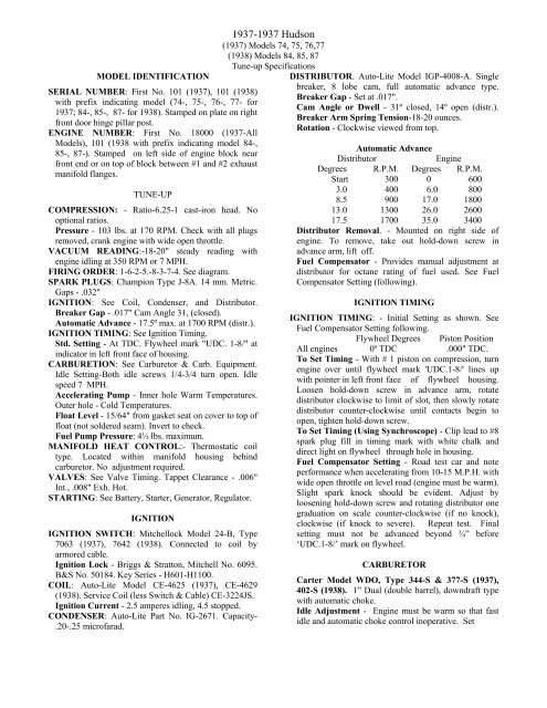
MODEL IDENTIFICATION<br />
SERIAL NUMBER: First No. 101 (<strong>1937</strong>), 101 (1938)<br />
with prefix indicating model (74-, 75-, 76-, 77- for<br />
<strong>1937</strong>; 84-, 85-, 87- for 1938). Stamped on plate on right<br />
front door hinge pillar post.<br />
ENGINE NUMBER: First No. 18000 (<strong>1937</strong>-All<br />
Models), 101 (1938 with prefix indicating model 84-,<br />
85-, 87-). Stamped on left side of engine block near<br />
front end or on top of block between #1 and #2 exhaust<br />
manifold flanges.<br />
TUNE-UP<br />
COMPRESSION: - Ratio-6.25-1 cast-iron head. No<br />
optional ratios.<br />
Pressure - 103 lbs. at 170 RPM. Check with all plugs<br />
removed, crank engine with wide open throttle.<br />
VACUUM READING:-18-20" steady reading with<br />
engine idling at 350 RPM or 7 MPH.<br />
FIRING ORDER: 1-6-2-5.-8-3-7-4. See diagram.<br />
SPARK PLUGS: Champion Type J-8A. 14 mm. Metric.<br />
Gaps - .032"<br />
IGNITION: See Coil, Condenser, and Distributor.<br />
Breaker Gap - .017" Cam Angle 31, (closed).<br />
Automatic Advance - 17.5º max. at 1700 RPM (distr.).<br />
IGNITION TIMING: See Ignition Timing.<br />
Std. Setting - At TDC. Flywheel mark "UDC. 1-8/" at<br />
indicator in left front face of housing.<br />
CARBURETION: See Carburetor & Carb. Equipment.<br />
Idle Setting-Both idle screws 1/4-3/4 turn open. Idle<br />
speed 7 MPH.<br />
Accelerating Pump - Inner hole Warm Temperatures.<br />
Outer hole - Cold Temperatures.<br />
Float Level - 15/64" from gasket seat on cover to top of<br />
float (not soldered seam). Invert to check.<br />
Fuel Pump Pressure: 4½ lbs. maximum.<br />
MANIFOLD HEAT CONTROL:- Thermostatic coil<br />
type. Located within manifold housing behind<br />
carburetor. No adjustment required.<br />
VALVES: See Valve Timing. Tappet Clearance - .006"<br />
Int., .008" Exh. Hot.<br />
STARTING: See Battery, Starter, Generator, Regulator.<br />
IGNITION<br />
IGNITION SWITCH: Mitchellock Model 24-B, Type<br />
7063 (<strong>1937</strong>), 7642 (1938). Connected to coil by<br />
armored cable.<br />
Ignition Lock - Briggs & Stratton, Mitchell No. 6095.<br />
B&S No. 50184. Key Series - H601-H1100.<br />
COIL: Auto-Lite Model CE-4625 (<strong>1937</strong>), CE-4629<br />
(1938). Service Coil (less Switch & Cable) CE-3224JS.<br />
Ignition Current - 2.5 amperes idling, 4.5 stopped.<br />
CONDENSER: Auto-Lite Part No. IG-2671. Capacity-<br />
.20-.25 microfarad.<br />
<strong>1937</strong>-<strong>1937</strong> <strong>Hudson</strong><br />
(<strong>1937</strong>) Models 74, 75, 76,77<br />
(1938) Models 84, 85, 87<br />
Tune-up Specifications<br />
DISTRIBUTOR. Auto-Lite Model IGP-4008-A. Single<br />
breaker, 8 lobe cam, full automatic advance type.<br />
Breaker Gap - Set at .017".<br />
Cam Angle or Dwell - 31º closed, 14º open (distr.).<br />
Breaker Arm Spring Tension-18-20 ounces.<br />
Rotation - Clockwise viewed from top.<br />
Automatic Advance<br />
Distributor<br />
Engine<br />
Degrees R.P.M. Degrees R.P.M.<br />
Start 300 0 600<br />
3.0 400 6.0 800<br />
8.5 900 17.0 1800<br />
13.0 1300 26.0 2600<br />
17.5 1700 35.0 3400<br />
Distributor Removal. - Mounted on right side of<br />
engine. To remove, take out hold-down screw in<br />
advance arm, lift off.<br />
Fuel Compensator - Provides manual adjustment at<br />
distributor for octane rating of fuel used. See Fuel<br />
Compensator Setting (following).<br />
IGNITION TIMING<br />
IGNITION TIMING: - Initial Setting as shown. See<br />
Fuel Compensator Setting following.<br />
Flywheel Degrees Piston Position<br />
All engines 0º TDC .000" TDC.<br />
To Set Timing - With # 1 piston on compression, turn<br />
engine over until flywheel mark 'UDC.1-8/' lines up<br />
with pointer in left front face of flywheel housing.<br />
Loosen hold-down screw in advance arm, rotate<br />
distributor clockwise to limit of slot, then slowly rotate<br />
distributor counter-clockwise until contacts begin to<br />
open, tighten hold-down screw.<br />
To Set Timing (Using Synchroscope) - Clip lead to #8<br />
spark plug fill in timing mark with white chalk and<br />
direct light on flywheel through hole in housing.<br />
Fuel Compensator Setting - Road test car and note<br />
performance when accelerating from 10-15 M.P.H. with<br />
wide open throttle on level road (engine must be warm).<br />
Slight spark knock should be evident. Adjust by<br />
loosening hold-down screw and rotating distributor one<br />
graduation on scale counter-clockwise (if no knock),<br />
clockwise (if knock to severe). Repeat test. Final<br />
setting must not be advanced beyond ¾” before<br />
‘UDC.1-8/’ mark on flywheel.<br />
CARBURETOR<br />
Carter Model WDO, Type 344-S & 377-S (<strong>1937</strong>),<br />
402-S (1938). 1” Dual (double barrel), downdraft type<br />
with automatic choke.<br />
Idle Adjustment - Engine must be warm so that fast<br />
idle and automatic choke control inoperative. Set
Carburetor (Cont’d)<br />
throttle lever stop screw so that idling speed is 7 MPH. Turn<br />
each idle adjusting screw, in succession in until engine<br />
begins to miss, then slowly out until engine fires smoothly.<br />
Final setting should be Y4-3/4 turn out from inner seated<br />
position and screws must be adjusted equally so that engine<br />
fires smoothly on all cylinders. Readjust throttle stop screw<br />
if necessary.<br />
Accelerating Pump Setting - Adjustable for minimum and<br />
maximum stroke as follows:<br />
Short stroke (inner hole) - Hot temperatures. Long stroke<br />
(outer hole) - Cold temperatures.<br />
CARBURETOR EQUIPMENT<br />
Fast Idle: Integral with carburetor.<br />
Setting - .018" throttle opening with choke valve closed<br />
Air Cleaner: - AC. #1528161 (std.), #1528160 (with Electric<br />
Hand) oil-wetted type. United (oil-bath type) optional. Fuel<br />
Pump: - AC. Type AK #1523289 (LHD), #1523313 (RHD),<br />
diaphragm type, standard. Type AB #1523290 (LHD),<br />
#1523314 (RHD), combination Fuel-and-vacuum pump<br />
optional.<br />
Gasoline Gauge: King-Seeley Electric type. K-S No..<br />
Dash Unit – No. 6190 (<strong>1937</strong> – Black dial, early cars), 6570<br />
(<strong>1937</strong> – Tan dial, Later cars), 6756 (1938)<br />
Tank Unit – No. 5835 (<strong>1937</strong>, 1938)<br />
- 2 -
BATTERY<br />
National, Type ST-319X (<strong>1937</strong>), HT-19 (1938 Orig.<br />
Equip.), L-19-2F (1938 Replacement). 6 volt, 19 plate, 108<br />
ampere hour (ST-319X), 115 ampere hour (HT-19 & L-<br />
19-2F) capacity (20 hour rate).<br />
Starting Capacity - 135 amperes for 20 minutes.<br />
Zero Capacity - 300 amperes for 4.3 minutes.<br />
Grounded Terminal - Positive (+) terminal. Grounded to<br />
left front fender support bracket. Engine grounded to frame<br />
by ground strap at bell housing.<br />
Dimensions - Length 11-¾", Width 7¼". Height 7-15/16".<br />
Location - In left front fender under hood. Accessible<br />
from engine compartment by taking out 3 slotted screws in<br />
cover flange (2 top, 1 rear) and removing cover.<br />
STARTER<br />
Auto-Lite Model MAB-4075. Armature MAB-2113. Drive-<br />
Inboard Barrel Type Bendix No. A-1673.<br />
Rotation-Counter - clockwise at commutator end.<br />
Brush Spring Tension-42-53 ozs. (new brushes). Cranking<br />
Engine - 150 R.P.M., 120-125 amperes, 5 v.<br />
Performance Data<br />
Torque R.P.M. Volts Amperes<br />
0 ft. lbs . 3700 5.5 60<br />
.6 1 “ “ 1910 5.5 100<br />
3.4 “ “ 1100 5.0 200<br />
6.6 “ “ 695 4.5 300<br />
10.15 “ “ 420 4.0 400<br />
15.8 “ “ Lock 3 582<br />
22.5 “ “ 44 Lock 4 775<br />
NOTE - Lock torque figures correct without switch.<br />
- 3 -
Starter (Cont’d)<br />
Removal: - Starter flange mounted on left front face of<br />
flywheel housing. To remove, take out flange<br />
mounting screws.<br />
Starting Switch: - Type SS-4001. Magnetic solenoid<br />
type mounted on starter. Controlled by pushbutton on<br />
instrument board (RBM Model 1815). Operative only<br />
with ignition on (and clutch disengaged on cars with<br />
Electric Hand).<br />
Switch Specifications<br />
Closes with terminal voltage of 4.0 volts or less.<br />
Remains closed until voltage drops to .75-2.0 volts.<br />
Current draw, 3 amperes at 6.0 volts.<br />
GENERATOR<br />
MODELS 74, 75, 76, 77<br />
Auto-Lite Model GCJ-4803A. Armature No.<br />
GCJ-2006. Third brush control type with external<br />
voltage regulation. Ventilated by fan on drive pulley.<br />
Maximum Charging Rate-25 amperes (cold), 22<br />
amperes (hot), 8.0 volts, 2500 R.P.M. Actual<br />
charging rate controlled by Voltage Regulator and<br />
dependent on battery condition.<br />
Charging Rate Adjustment - Maximum output<br />
controlled by third brush. Do not adjust third brush for<br />
output greater than shown in table below (with field<br />
terminal grounded to render regulator inoperative).<br />
Actual charging rate controlled by regulator setting.<br />
See Regulator Section below.<br />
Cold Performance Data Hot<br />
Amperes Volts R.P.M. Amperes Volts R.P.M.<br />
0 6.4 760 0 6.4 850<br />
4 6.65 920 4 6.7 1020<br />
8 6.9 1080 8 7.0 1240<br />
12 7.2 1240 12 7.3 1400<br />
16 7.45 1400 16 7.6 1650<br />
20 7.7 1580 20 7.9 2100<br />
25 8.0 2500 22 8.0 2700<br />
Rotation - Counter-clockwise at commutator end.<br />
Brush Spring Tension - 53 ozs. max. (new brushes).<br />
Field Current - 1.9-2.1 amperes at 6.0 volts.<br />
Motoring Current - 4.0-4.4 amperes at 6.0 volts.<br />
Removal: - Generator pivot mounted at left front of<br />
engine with fan belt drive. To remove, take out clamp<br />
bolt and two pivot bolts.<br />
Belt Adjustment: - Loosen clamp bolt and pivot bolts,<br />
swing generator out until slack in belt midway between<br />
generator and fan pulleys is ¾-1¼" (measured<br />
from straightedge across pulleys).<br />
GENERATOR<br />
MODELS 84, 85, 87<br />
Auto-Lite Model GDF-4802A. Armature No.<br />
GDF2006. Third brush control type with external<br />
voltage regulation. Ventilated by fan on drive pulley.<br />
Maximum Charging Rate - 32.0 amperes (cold), 29.5<br />
amperes (hot), 8.0 volts, 3100 R.P.M., 30-35 M.P.H.<br />
Actual charging rate controlled by Voltage Regulator<br />
and dependent on battery condition.<br />
Charging Rate Adjustment - Maximum output<br />
controlled by third brush. Do not adjust third brush for<br />
out put greater than shown in table below (with<br />
field terminal grounded to render regulator<br />
inoperative). See Regulator Section below.<br />
NOTE - Standard third brush setting 21/8 commutator<br />
bars from nearest main brush.<br />
Performance Data<br />
Cold<br />
Hot<br />
Amperes Volts R.P.M. Amperes Volts R.P.M.<br />
0 6.4 920 0 6.4 1000<br />
4 6.6 1030 4 6.6 1140<br />
8 6.8 1140 8 6.85 1280<br />
12 7.0 1300 12 7.1 1440<br />
16 7.25 1460 16 7.3 1640<br />
20 7.45 1650 20 7.55 1840<br />
24 7.65 1880 24 7.75 2220<br />
28 7.9 2220 28.2 8.0 3200<br />
32 8.0 3100<br />
Rotation - Counter-clockwise at commutator end.<br />
Brush Spring Tension - 53 ozs. max. (new brushes).<br />
Field Current - 1.90-2.10 amperes at 6.0 volts.<br />
Motoring Current - 5.3-5.9 amperes at 6.0 volts.<br />
Removal: - Generator pivot mounted at left front of<br />
engine with fan belt drive.. To remove, take out clamp<br />
bolt and two pivot bolts.<br />
Belt Adjustment: - Loosen clamp bolt and pivot bolts,<br />
swing generator out until slack in belt midway between<br />
generator and fan pulleys is ¾" (measured with<br />
straight edge across pulleys).<br />
REGULATOR<br />
- 4 -<br />
Auto-Lite Model VRD-4003A, 4003B (GCJ-4803A<br />
Gen.), VRD-4008A (GDF-4802A Gen.) . Voltage<br />
Type. Cutout Relay and vibrating type Voltage<br />
Regulator in case on dash. Cutout Relay has extra set<br />
of ground contacts for generator charge signal control.<br />
NOTE - Regulator case cover is sealed. Serviced on<br />
exchange basis If seals not broken. Cover must be<br />
removed to make adjustments.<br />
Cutout Relay<br />
Cuts In - 6.4-7.0 volts Cold. Approx. 10 MPH.<br />
Cuts Out - L.5-3.0 ampere discharge (Before Serial<br />
No. 2T-000001), 1.5-4.5 amperes (After 2T-000001).<br />
Contact Gap - .015- minimum (with ground contacts<br />
closed-ground contacts must be open with main<br />
contacts closed).<br />
Air Gap - .0340 Min., .038" Max. with contacts open.<br />
Measure at hinge end of core.
Regulator (Cont’d)<br />
Voltage Regulator<br />
Setting (VRD-4003-A) - 7.5-7.8 volts at 70º F (Before<br />
#811-000001), 7.35-7.65 volts at 70º F (After #811-<br />
000001).<br />
Setting (VRD_4003-B) - 7.8-8.1 volts at 70º F (Before<br />
#811-000001), 7.35-7.65 volts at 70º F (After #811-<br />
000001).<br />
Setting (VRD-4008A) - 7.35-7.65 volts at 70º F.<br />
To Check - Connect ammeter in charging line at 'B'<br />
terminal on regulator (use short heavy leads), connect<br />
voltmeter between regulator 'B' and 'GD' terminals.<br />
Operate generator, charging fully charged battery, at<br />
speed equivalent to 30 MPH. car speed until voltage is<br />
steady. Voltmeter reading should be within limits of<br />
7.4-7.9 volts (VRD-4003- before #81-1-000001), 7.8-<br />
8.1 volts (VRD-4003-B before #8R-000001), 7.1-7.8<br />
volts (all models after #8R-000001). If outside these<br />
limits, regulator is defective.<br />
To Adjust (with cover removed) - Change regulator<br />
armature spring tension slightly by bending lower<br />
spring hanger. Check setting as directed above.<br />
Contact Gap - 010" Min., .0201, Max. with armature<br />
against stop pin<br />
Air Gap - .0595-.6625" with contacts just opening.<br />
LIGHTING<br />
LIGHTING: - Headlamps-Hall, pre-focused type with<br />
interchangeable lenses. Upper and lower beams (lower<br />
beam deflected slightly to right) controlled by foot<br />
selector switch with lighting switch in driving (right<br />
hand) position.<br />
Headlamp Adjustment - Aim headlamps straight<br />
ahead with top of beam at lamp center height at 25,<br />
(car unloaded, upper beams lighted). Headlamps<br />
aimed by means of two screws on underside of<br />
headlamp body. Vertical movement obtained by<br />
turning both screws equally in or out horizontal<br />
movement by turning one screw in until half desired<br />
movement obtained and completing movement by<br />
turning opposite screw out an equal amount.<br />
Switches<br />
Lighting - R.B.M.<br />
Foot Selector - R.B.M. No. 1076.<br />
Dome Light - R.B.M. No. 1220.<br />
Stop Light - R.B.M. No. 965.<br />
Bulb Specifications<br />
Position Candlepower Mazda No.<br />
Headlamps 32-32 2331<br />
Headlamps (export) 21-50 2520D<br />
Park, Instrument, Service 11/2 55<br />
License, Fender 3 63<br />
Stop-Tail 21-3 1158<br />
Dash Signals 1 51<br />
Dome 15 87<br />
MISC. ELECTRICAL<br />
SIGNAL LIGHTS: - Teleflash Generator Charging<br />
Indicator and Oil Pressure Indicator mounted on<br />
instrument panel.<br />
FUSES: - Lighting-Two 20 ampere capacity mounted on<br />
lighting switch (<strong>1937</strong>), on fuse block on lower flange<br />
of instrument panel on left side (1938).<br />
HORNS: Standard - Klaxon (Delco-Remy) Model K-33S<br />
(<strong>1937</strong>), Sparton (1938). Twin Horns operated by<br />
Delco-Remy or R-B-M relay.<br />
Optional - Klaxon K-11-F, Type 2111 (left--low note),<br />
2118 (right-high note), twin horns, blended tone with<br />
Delco Remy horn relay (optional--outside mounting).<br />
NOTE - Data below for Delco-Remy equipment.<br />
Horn Current (6 volts) Air Gap<br />
K-33-S, 2051 (low note) 11-13amps 042-.04611<br />
K-33-S, 2052 (high note) 10-12 " 032-.03611<br />
K-33-F, 2117 (low note) 11-13 " .040-.044"<br />
K-33-F, 2118 (high note) 9-11 " .032-.036"<br />
Horn Relay: - Model 271-A (with Klaxon horns).<br />
Contacts close 2.7-4.0 volts.<br />
Contact Gap -.02011. Air Gap - .015".<br />
NOTE - R.B.M. Model 780 horn relay also used.<br />
ENGINE<br />
ENGINE SPECIFICATIONS: - 8 cylinder, 'L' head<br />
type.<br />
Bore - 3", Stroke - 4½".<br />
Displacement - 254 cubic inches. Rated HP-28.8.<br />
Developed Horsepower - 122 HP. at 4200 R.P.M.<br />
Compression Ratio - 6.25-1 No Optional Ratios.<br />
Compression Pressure - 103 lbs. at 170 R.P.M.<br />
cranking speed (plugs removed, throttle wide open).<br />
Vacuum Reading - 18-21" at 350 RPM. or 7 MPH.<br />
PISTONS: - Own Lo-Ex aluminum alloy, IT' slot, cam<br />
ground type. Use finished replacement pistons.<br />
Weight - 10.5 ozs. stripped. Length-3 3/16".<br />
Removal - Pistons and rods may be removed from<br />
above or below.<br />
Clearance - .0161, top, .0021, skirt (see below).<br />
Fitting New Pistons: - 3-4 lbs. tension should be<br />
required to withdraw .0015" feeler 1/2" wide from<br />
between piston and cylinder wall on side opposite slot<br />
at right angles to pin bosses.<br />
Installing Pistons: - Slot away from camshaft side.<br />
PISTON RINGS: - Two compression, one oil ring above<br />
pin, one oil ring below pin. Rings positioned by pin in<br />
groove.<br />
Models 74, 75, 76, 77 (<strong>1937</strong>)<br />
Ring Width End Gap Side Clearance<br />
Compression 3/32" .009-.011" .001"<br />
Oil (both) 3/16" .009-.011" .001"<br />
Models 84, 5, 7 (1938)<br />
Ring Width End Gap Side Clearance<br />
Compression 3/32" .005-.010" .001"<br />
Oil (both) 3/16" .005" .001"<br />
- 5 -
Engine (Cont’d)<br />
PISTON PIN: - Diameter - 3/4". Length - 2-7/16".<br />
Pin floats in Piston and rod, held by locking rings.<br />
Pin hole in rod bronze-bushed. Pins furnished std.,<br />
.002-, .005-, .010” oversize.<br />
Pin Fit in Piston - .00031' clearance or hand push fit<br />
with piston heated to 200º F.<br />
Pin Fit in Rod Bushing - .0003" clearance.<br />
CONNECTING ROD: Length - 8-3/16".<br />
Weight - 29.4 ozs. (<strong>1937</strong>), 30.3 ozs. (1938).<br />
Crankpin Journal Diameter - 1-15/16".<br />
Clearance - 001". Side play - .006-.010".<br />
Bearing Adjustment: Laminated shims (<strong>1937</strong>), No<br />
adjustment (1938-no shims). Replace rods.<br />
Installing Rods: - Offset. Install rods with widest half<br />
of bearing toward rear (#1, 3, 5, 7), toward front 42, 4,<br />
6, 8). Oil scoop on all rods toward camshaft.<br />
CRANKSHAFT: - 5 bearing with integral counterweights.<br />
Journal Diameters - #1, 2-9/32"; #2, 2-5/16"; #3,<br />
2-11/32"; #4, 2-3/8"; #5, 2-13/32".<br />
Bearing Type - Bronze-backed, babbitt-lined.<br />
Furnished std. and unfinished (1/ 32” extra stock -<br />
ream to desired undersize). Clearance - .001".<br />
Bearing Adjustment: - Shims.<br />
End Thrust: - Taken by center bearing. Replace<br />
bearing to adjust. Endplay.006-.012".<br />
CAMSHAFT: - Five bearing. Gear driven.<br />
Journal Diameters - #1, 2-1/32"; #2, 2"; #3,1-31/32-;<br />
#4,1-15/16"; #5, 1½".<br />
Bearing Clearance - 0025".<br />
End Thrust: - Taken by thrust washer assembled<br />
between front face of crankcase and rear side of<br />
camshaft front flange, and by spring- loaded<br />
button in camshaft hub and thrust plate on gear cover.<br />
See that spring and button in place under cover.<br />
Timing Gears: - Crankshaft gear cast-iron. Camshaft<br />
gear GE. or Continental Diamond Fibre Bakelite.<br />
Note: 1941 Type Timing Gear Set can be installed on<br />
these models (tooth angle redesigned to provide quieter<br />
operation).<br />
Camshaft Setting: - Mesh marked crankshaft gear<br />
tooth between two marked teeth on camshaft gear.<br />
VALVES: - Lighter valves (smaller stem diameter) used,<br />
than on previous models. New pilot size necessary for<br />
servicing tools.<br />
Head Diameter Stem Diameter Length<br />
Intake 1½" 3/8" ('37), 11/32" ('38) 5-3/32"<br />
Exhaust 1-3/8" 3/8" ('37),11/32" ('38) 5-3/32"<br />
Seat Angle Lift Side Clearance<br />
Intake 45º 11/32" .0015-.003"<br />
Exhaust 45º 11/32" .003-.005"<br />
Valve Guides: - 2-9/16" long. Top 15/16" below top of<br />
block. Finish ream to size after installation.<br />
Valve Springs: - Springs are cadmium plated, Dampners<br />
originally used on bottom of all springs, but<br />
recommended that they be omitted whenever<br />
valves are serviced. Spring check (out of engine) - 34<br />
lbs. min. at 2".<br />
Spring Pressure Spring Length<br />
Valve Closed 44 lbs 2"<br />
Valve Open 102 lbs 1-21/32"<br />
Valve Lifters: - Roller shoe type, fitted In removable<br />
guides.<br />
VALVE TIMING<br />
Tappet Clearance - 006", Intake, .008", Exhaust,<br />
engine hot.<br />
Valve Timing: - See Camshaft Setting above.<br />
Intake Valves - Open 10º 40' BTDC. Close 60º<br />
ALDC.<br />
Exhaust Valves - Open 50º BLDC. Close 18 0186 44'<br />
ATDC. These figures correct with .010" tappet<br />
clearance.<br />
To Check Timing - Set tappet clearance #1 intake<br />
valve at .010". This valve should open with piston 10º<br />
40' or .0494" BTDC when point on flywheel<br />
approximately 3.97 teeth before 'UDC.1-8/' mark lines<br />
up with pointer in hole in left front face of<br />
flywheel housing. Reset tappet clearance at .006" hot.<br />
LUBRICATION<br />
LUBRICATION: - Duo-flo (pressure & positive splash).<br />
Oil Pump: - Oscillating plunger type, gear driven by<br />
camshaft. Mounted on right side of crankcase.<br />
Normal Oil Pressure - 3 lbs. (no gauge).<br />
Oil Pressure Regulator: - Located on right side of<br />
crankcase at rear. Opens at 3 lbs. Not adjustable.<br />
Oil Pressure Indicator: - Teleflash Oil Pressure<br />
indicator.<br />
Crankcase Capacity: - 7 quarts (refill), 9 quarts (dry).<br />
COOLING<br />
COOLING SYSTEM: - Water Pump. Centrifugal, belt<br />
driven, packless type.<br />
Removal - With water drained and fan belt removed,<br />
disconnect pump hoses, remove mounting bolts and lift<br />
off fan and pump assembly.<br />
Thermostat: - Mounted in cylinder head water outlet.<br />
Setting - Start to open 150-155º F. Fully open 185º F.<br />
Water Capacity: 20 quarts (<strong>1937</strong>), 171/2 quarts (1938).<br />
CLUTCH<br />
CLUTCH: - Own make. Single plate, cork insert type<br />
operating in oil.<br />
- 6 -
Clutch (Cont’d)<br />
Automatic Clutch Control: - Optional equipment.<br />
Driven Member - Thickness .203". Inside Diameter<br />
6.375" Outside Diameter 9.75". Facing 108 Cork<br />
Inserts.<br />
Adjustment: -Pedal free movement must be 1½". To<br />
adjust, remove clevis pin at lower end of connecting<br />
link on throw-out shaft lever, loosen locknut, turn<br />
clevis. On cars with Automatic Clutch control, check<br />
setting whenever clutch adjusted.<br />
Removal: - Remove transmission (see Transmission<br />
Removal following), take out 16 clutch cover cap<br />
screws and remove clutch assembly from below.<br />
TRANSMISSION<br />
TRANSMISSION: - Own Make. Constant-mesh, helical<br />
gear (second & high), sliding spur (low & reverse).<br />
NOTE - Shifter Rail Locks used to prevent gear<br />
engagement with clutch engaged.<br />
Electric Hand Transmission Control - Optional.<br />
Removal: - Remove Electric Hand and Automatic<br />
Clutch Control units and wiring from transmission<br />
first, if car model so equipped. Disconnect<br />
transmission side bumpers, interlock straps,<br />
speedometer cable, drive shaft at front universal.<br />
Support engine at rear, free rear engine mounting.<br />
Take out bell housing-to-engine mounting bolts, pull<br />
transmission straight back and remove.<br />
UNIVERSALS<br />
UNIVERSAL JOINTS: - Spicer. 1281 (front), 1288<br />
(rear).<br />
REAR AXLE<br />
REAR AXLE: - Own make. Semi-floating, spiral bevel<br />
Ratios (<strong>1937</strong>) - 4.11-1 Std., 4.56-1, 3.89-1, 3.56-1<br />
Optional<br />
Ratios (1938) - 4 1/9-1 Std., 4 5/9-1, 3 5/9-1, 3 8/9-1<br />
Optional<br />
Backlash - .0005-.003". Screw adjustment.<br />
Removal: - Remove rear wheel and hub assembly (use<br />
screw type hub puller only), take out four nuts on<br />
bearing cap bolts, push bolts out through backing<br />
plate (allows cap removal without disturbing hand<br />
brake operating link), remove shims, pull wheel<br />
bearing and axle shaft, disconnect driveshaft at<br />
rear universal joint, remove 8 nuts from axle housing<br />
stud bolts, withdraw differential carrier.<br />
Wheel Bearing Adjustment: - Controlled by shims<br />
under bearing cap. Measure endplay by dial indicator<br />
clamped to backing plate with plunger against end of<br />
axle shaft. To adjust, remove bearing caps (as directed<br />
above), add or remove shims equally at both wheels.<br />
Endplay - .004-.010".<br />
SHOCK ABSORBERS<br />
Delco. Direct acting hydraulic types: As follows:<br />
Front - Model 1175S (<strong>1937</strong>), 1164S (1938).<br />
Rear - Model 1174T (<strong>1937</strong>),1163T (1938).<br />
FRONT SUSPENSION<br />
Front Suspension: - Conventional 'I' beam section front<br />
axle with Elliott type ends and semi-elliptic springs.<br />
Axle alignment maintained by torque arm at each<br />
end (rubber-bushed bolt at frame). Torque Arms.<br />
Kingpin Inclination – 7º crosswise.<br />
Caster - 1-2º and equal within ½º for both wheels. To<br />
adjust, loosen cap screws at forward end of torque arm,<br />
insert shim between arm and axle at upper<br />
screw or remove shim at lower screw to decrease<br />
caster, remove shim at upper screw or Insert shim at<br />
lower screw to increase caster. Shims .020"<br />
thick, change caster ½".<br />
Camber - 1-1½º. Not adjustable.<br />
Toe In: - 0-1/8" measured 10" up from ground. Adjust<br />
by loosening clamp bolts and turning tie rod.<br />
Steering Geometry - Inner wheel 20º. Outer 17¾º.<br />
STEERING GEAR<br />
Steering Gear: Gemmer Model 305 Worm-and-Roller<br />
type with "push-pull" adjustments.<br />
BRAKES<br />
BRAKES: - Service-Bendix Hydraulic, Duo-servo Single<br />
anchor type. Mechanical follow-up (pedal linked to<br />
hand brake cables) provided. Hand lever applies rear<br />
service brakes.<br />
Drum - Alloy-steel. Diameter-11-1/16".<br />
Lining - Moulded (primary), woven (secondary).<br />
Width 1¾". Thickness 7/32" (<strong>1937</strong>), 3/16" (1938).<br />
Length per wheel 23-15/16".<br />
Clearance - .010" at heel and toe of each shoe.<br />
Hand Brake: - See Service Brakes above.<br />
Hill-Holder: Optional.<br />
- 7 -


