Light Vehicle Inspection Manual (PDF 7MB) - Transport
Light Vehicle Inspection Manual (PDF 7MB) - Transport
Light Vehicle Inspection Manual (PDF 7MB) - Transport
- No tags were found...

Create successful ePaper yourself
Turn your PDF publications into a flip-book with our unique Google optimized e-Paper software.
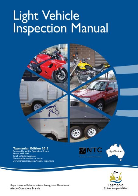
<strong>Light</strong> <strong>Vehicle</strong><strong>Inspection</strong> <strong>Manual</strong>Tasmanian Edition 2013Produced by <strong>Vehicle</strong> Operations BranchPhone: 6233 5347Email: ais@dier.tas.gov.auThis manual is available on line at:www.transport.tas.gov.au/vehicle_inspections<strong>Light</strong> <strong>Vehicle</strong>sDepartment of Infrastructure, Energy and Resources<strong>Vehicle</strong> Operations Branch
Produced by<strong>Vehicle</strong> Operations BranchDepartment of Infrastructure,Energy and ResourcesGPO BOX 936Hobart Tasmania 7001Phone: 03 6166 3265Email: ais@dier.tas.gov.auThis manual is available online at:www.transport.tas.gov.au/vehicle_inspections2 <strong>Light</strong> <strong>Vehicle</strong> <strong>Inspection</strong> <strong>Manual</strong> Version 11, December 2013
ContentsVery Important Advice 9Administration of this <strong>Manual</strong> 11<strong>Light</strong> Motor <strong>Vehicle</strong> <strong>Inspection</strong> Checklist 12Section 1<strong>Vehicle</strong> Identification 151.1 Check the identity of the <strong>Vehicle</strong> 15Section 2Brakes 172.1 Check the operation of the brake controls 172.2 Inspect the condition of visible brake components 182.3 Brake testing with a roller brake tester 19Section 3Towing Attachments 213.1 Visually inspect the towbar and its mounting on the vehicle body 21Section 4Steering and Suspension 234.1 With the engine running, check the operation of the steering bymoving the steering wheel, or, on cycle type vehicles, the handle 234.2 Visually inspect all steering components under the bonnet andunder the vehicle 244.3 Examine the idler arm 244.4 Visually inspect the suspension 24Section 5Wheels and Tyres 275.1 Visually inspect the inside and outside of each road wheel 275.2 Visually inspect each road tyre 275.3 Tyres on four wheel drive/off road vehicles 285.4 Measure the wheel track, where modified from standard, takingmeasurement from the centre of the tyres 28Section 6Body Condition 296.1 Check the operation of all doors, door locks and latches and thebonnet lock and latches 296.2 Visually inspect the windscreen and front side windows 296.3 Test the light transmittance level of the windscreen, side andrear windows 30<strong>Light</strong> <strong>Vehicle</strong> <strong>Inspection</strong> <strong>Manual</strong>Version 11, December 2013 3
6.4 Visually inspect body panels, chassis and sub frame for dangerousprotrusions and rust 316.5 Dimensions 326.6 Rear overhang 326.7 Inspect the wheel arches/mudguards and mudflaps, with the wheelsin the “straight ahead” position 326.8 Visually inspect rear vision mirrors 336.9 Visually inspect and check the operation of the windscreenwipers and windscreen washers 336.10 Check the operation of the horn 336.11 Visually inspect the front and rear number plates 336.12 Where ADR25 applies, check the operation of the anti-theft/steering lock 346.13 Where ADR42 applies, check the operation of the windscreen demister 346.14 Speedometer 34Section 7Seats and Seatbelts 357.1 Check seats. 357.2 Check the operation of seats, seat belts, buckles and other restraints,and inspect webbing and metal stalks 35Section 8<strong>Light</strong>ing 378.1 Visually inspect the compulsory reflectors fitted to the rearof the vehicle 378.2 Visually inspect and check the operation of all lights fitted to the vehicle 378.3 Visually inspect and check condition of all lights fitted to the vehicle 398.4 Visually inspect and check light switch operation 398.5 Visually inspect front and rear lights for the presence of tinted covers 398.6 Using a headlight tester, check the aim of the headlights 398.7 Visually inspect the headlights 40Section 9Engine Compartment & Driveline 419.1 Visually inspect the engine, transmission and driveline for oil leaks 419.2 Visually inspect engine, transmission and driveline components 419.3 Visually inspect the electrical system 419.4 Visually inspect the exhaust system 429.5 Visually inspect the fuel system 429.6 Where it is evident that a vehicle is emitting significantly higherexhaust noise than normal, conduct a stationary noise test 43Section 10Fuel Systems LPG/LNG/CNG <strong>Vehicle</strong>s 4510.1 Visually inspect for the presence of an approved LPG/LNG/CNGmodification plate and number plate labels. 4510.2 Visually inspect the LPG/LNG or CNG container 4610.3 Visually inspect the container anchorages and straps 4710.4 Visually inspect remote filled internally mounted containers 484 <strong>Light</strong> <strong>Vehicle</strong> <strong>Inspection</strong> <strong>Manual</strong> Version 11, December 2013
10.5 Visually inspect direct filled internally mounted containers 4810.6 Visually inspect externally mounted containers 4810.7 Visually inspect ullage and safety valves 4910.8 Visually inspect hydrostatic relief valves 4910.9 Visually inspect fuel lines, joints and connections 4910.10 Visually inspect shut off devices, converters (vaporiser regulators),fuel selectors and air/gas mixers. 4910.11 Visually inspect the lpg electrical wiring 5010.12 Test the operation of the fuel containment system 50Section 11Petrol/Diesel <strong>Vehicle</strong>s 5111.1 Visually inspect the fuel system 5111.2 Visually inspect fire extinguisher (where required eg omnibuses,caravans and tow trucks) 51Section 12Motorcycles 5312.1 Visually inspect the condition of the brake controls 5312.2 Check the operation of the brake controls 5312.3 Inspect the condition of visible brake components 5312.4 Check the operation of the parking brake on ADR 33 cycles fittedwith side-car outfits and motor tricycles 5412.5 Visually inspect the towbar and its mounting to the frame 5412.6 Visually inspect all steering components 5512.7 Visually inspect the suspension 5512.8 Inspect both sides of each road wheel 5612.9 Visually inspect each road tyre 5612.10 Visually inspect body panels, chassis and frame for dangerousprotrusions and rust 5712.11 Inspect the mudguards 5712.12 Seating 5712.13 Visually inspect rear vision mirror(s) 5712.14 Check the operation of the horn 5812.15 Visually inspect any exposed drive chain or belt or shaft 5812.16 Visually inspect the number plate 5812.17 Visually inspect the compulsory reflectors fitted to the rear of the cycle 5812.18 Visually inspect and check the operation of all lights fitted to the cycle 5812.19 Inspect electrical control switches 5912.20 Visually inspect front and rear lights for the presence of tinted covers 5912.21 Using a headlight tester, check the aim of the headlight(s) 6012.22 Visually inspect the headlight(s) 6012.23 Visually inspect the engine, remote oil reservoirs, transmissionand driveline 6012.24 Visually inspect the fuel system 6012.25 Visually inspect the exhaust system 6112.26 Where it is evident that a motorcycle is emitting significantly higherexhaust noise than normal, conduct a stationary noise test inaccordance with Appendix B 61<strong>Light</strong> <strong>Vehicle</strong> <strong>Inspection</strong> <strong>Manual</strong>Version 11, December 2013 5
Section 13Motor Homes 6313.1 Visually inspect the living quarters 63Section 14<strong>Light</strong> Trailers & Caravans 6514.1 Inspect the trailer for brake requirements 6514.2 Inspect the condition of visible brake components 6514.3 Brake testing of trailers fitted with override brakes 6514.4 Brake testing of trailers fitted with brakes other than override brakes 6514.5 Where fitted, test the parking brake 6614.6 Where fitted, inspect the emergency braking system/brake awaybraking system 6614.7 Visually inspect the trailer coupling, drawbar and mountings onthe trailer body 6614.8 Visually inspect safety chains or ropes 6714.9 Visually inspect all suspension components 6714.10 Visually inspect the inside and outside of each road wheel 6814.11 Visually inspect each road tyre 6814.12 Check Wheel bearings 6814.13 Check the operation of doors, gates and flap 6814.14 Visually inspect body panels, chassis and frame 6814.15 Inspect the mudguards 6914.16 Visually inspect the number plate 6914.17 Visually inspect mandatory reflectors 6914.18 Visually inspect and check the operation of all lights fitted to the vehicle 7014.19 Rear overhang 7114.20 Dimensions 7114.21 Visually inspect the livng area of a caravan 71Section 15<strong>Light</strong> <strong>Vehicle</strong> Standards – Specific to Taxis 7315.1 <strong>Vehicle</strong> Suitability 7315.2 Visually Inspect Taxi Meter, 2 Way Radio, (Including Radio DispatchVisual Display Units) and Internal Tariff Indicators 7315.3 Visually Inspect External Indicators 7415.4 Visually Inspect Security Camera System 7515.5 Visually Inspect the Outside Doors 7515.6 Visually Inspect Inside the <strong>Vehicle</strong>s 7515.7 Additional Security Cameras Installed (Optional) 7615.8 Wheelchair Accessible Taxis (WAT) 7615.9 Restricted Hire <strong>Vehicle</strong> - General 77Section 16<strong>Light</strong> <strong>Vehicle</strong> Standards - Specific to Driving Instructor <strong>Vehicle</strong>s 7916.1 Visually inspect the <strong>Vehicle</strong>s Dual Controls 796 <strong>Light</strong> <strong>Vehicle</strong> <strong>Inspection</strong> <strong>Manual</strong> Version 11, December 2013
8 <strong>Light</strong> <strong>Vehicle</strong> <strong>Inspection</strong> <strong>Manual</strong> Version 11, December 2013
Very Important AdviceThe purpose of this manual is to provide information on the minimum roadworthiness and safety standards for vehiclesused on Tasmanian roads.Every effort has been made to provide comprehensive advice, however this manual cannot cover all eventualities,especially in the case of non-standard and modified vehicles.If you think a vehicle is deficient or has a safety defect of any sort which is not covered in this manual please seek advicefrom the Department of Infrastructure, Energy and Resources by phone on 62335214, or email transport@dier.tas.gov.au<strong>Light</strong> <strong>Vehicle</strong> <strong>Inspection</strong> <strong>Manual</strong>Version 11, December 2013 9
10 <strong>Light</strong> <strong>Vehicle</strong> <strong>Inspection</strong> <strong>Manual</strong> Version 11, December 2013
Administration of this <strong>Manual</strong>Important InformationThis manual has been checked and is believed to be correct at the time it was released. The version number and releasedate is shown on the bottom of each page.The applicable legislation takes precedence over the contents of this manual and in the unlikely event there is a discrepancyin the information provided, the legislation will always prevail.CustodianThis manual is administered and maintained by:Manager, <strong>Vehicle</strong> Standards<strong>Vehicle</strong> Operations BranchLand <strong>Transport</strong> Safety DivisionDepartment of Infrastructure Energy and ResourcesGPO Box 935 Hobart Tasmania 7001Publication and DisseminationThis manual may be downloaded from the Department of Infrastructure, Energy and Resource’s website atwww.transport.tas.gov.auVersion ControlThis version supersedes and takes precedence over the previous version, which was released in June 2013.Suggestions for ImprovementThis manual is a “live document” that will require revision from time to time to include improvements in vehicle technologyand to accommodate changes in the legislation etc. Suggestions for improvements and notification of any corrections arewelcomed, please phone (03) 6233 5314, email ais@dier.tas.gov.au or fax (03) 6233 5210.EnquiriesTechnical enquiriesMay be made by phoning (03) 6166 3263Administration enquiriesMay be made to the Manager, <strong>Vehicle</strong> Standards, Accreditation/AIS Compliance, email ais@dier.tas.gov.au orphone (03) 6166 3263<strong>Light</strong> <strong>Vehicle</strong> <strong>Inspection</strong> <strong>Manual</strong>Version 11, December 2013 11
Tasmanian <strong>Inspection</strong> <strong>Manual</strong> for <strong>Light</strong> <strong>Vehicle</strong>s<strong>Light</strong> Motor <strong>Vehicle</strong> <strong>Inspection</strong> Checklist<strong>Light</strong> Motor <strong>Vehicle</strong> <strong>Inspection</strong> Checklist1. IDENTITY Mountings 13. ENGINE & DRIVELINE Compliance Plate Locking/snatch test Mountings VIN/Chassis No 8. UNDER BONNET CHECK Oil leaks Engine No Master Cylinder Universal joints2. ELECTRICALCHECK Headlight/parklights Headlightalignment Engine oil leaks Engine fuel leaks Air Cleaner Centre bearing14. EXHAUST Exhaust leaks Tail lights Engine mountings Mountings Indicators Exhaust system Clearance–hoses/wiring Brake lights Battery security Catalytic Converter Reverse lights Wiring security 15. REAR SUSPENSION Reflectors Steering shaft Control arms Lens condition Steering coupling Bushes Windscreen wipers Power steering leaks Ball joints Windscreenwashers9. STEERING Springs/shock absorbers Horn Steering box Bump stops3. BODY CHECK Steering rack Modifications Rust Linkages Suspension height Protrusions Tie rod ends 16. WHEELS & TYRES REAR Bonnet safetycatch Idler arm Condition Windows 10. FRONT SUSPENSION Tread pattern Windowtint % Control arms Tyre speed rating4. INSIDE CHECKS Bushes Tyre load rating Heater/demister Ball joints Rims Heater fan Springs/shock absorbers After market tyres/rims ABS/SRS lights Bump stops Wheel track: Pedal condition Modifications 17. FUELTANK Brake pedal height Handbrakeoperation Suspensionheight…..mm11.WHEELS &TYRESFRONT Mounting Conditionmm12 <strong>Light</strong> <strong>Vehicle</strong> <strong>Inspection</strong> <strong>Manual</strong> Version 11, December 2013Version 4 – 1 May 2009 Page 10
Inhibitor switch(auto) ConditionTasmanian <strong>Inspection</strong> <strong>Manual</strong> for <strong>Light</strong> <strong>Vehicle</strong>s Fuel leaks Steering wheel Tread pattern Fuel line Steering wheelfreeplay Tyre speed rating18. LPG GAS Window operation Tyre load rating Gas compliance certificate Door operation Rims 19. BODY & FRAME5. MIRRORS After market tyres/rims Rust ConditionWheel trackmm Cracks Mountings 12. BRAKES Bends/kinks6. SEATS Pipes and hoses Modifications Condition Discs and drums Mudguards Adjustments Fluid leaks 20 CAMPERVAN Mountings Caliper/hose security Gas/electrical compliance7. SEAT BELTS Pads and linings Fire extinguisher Condition Linkages 2 nd stage manufacture plate ComplianceMOTORCYCLE Security/noise1. IDENTITY 9. BODY & FRAME CHECK Compliance Plate Fuel tank VIN/Chassis No Seat/s/condition/mounting Engine No Mudguards2. ELECTRICAL CHECK Bends/kinks/cracks/rust Headlight/park lights Modifications Headlight alignment Tail lights Indicators Brake lights Reflectors Lens conditions Horn Battery securityLIGHT TRAILER/CARAVAN10. IDENTITY Compliance Plate VIN/Chassis No Unladen mass GTM11. DRAW BAR Master cylinder/Brake away3. HANDLEBARS Pipes and hoses Mirrors Linkages Throttle return Tow coupling Clutch lever Safety chain<strong>Light</strong> <strong>Vehicle</strong> <strong>Inspection</strong> <strong>Manual</strong>Version 11, December 2013 13Version 4 – 1 May 2009 Page 11
Tasmanian <strong>Inspection</strong> <strong>Manual</strong> for <strong>Light</strong> <strong>Vehicle</strong>s Handlebar security Draw bar Hand grips12. ELECTRICAL CHECKS4. BRAKES Tail lights Master cylinder/s Indicators Pipes and hoses Brake lights Discs and drums Side clearance lights Fluid leaks Reflectors Caliper/hose security Lens conditions Pads and linings13. SUSPENSION Linkages Wheel bearings5.SUSPENSION Springs Front forks and braces Shackles Shock absorbers Axle Springs14. BRAKES Swing arm bushesPipes/hoses/leaks Axle location and lock nuts Pads/linings Drive chain/belt/ and cover Drums/caliper6. ENGINE 15. WHEELS &TYRES Oil/fuel leaks Condition Mountings Tread pattern Sprocket/pulley cover Rims Air filters16. BODY & FRAME CHECK Fuel lines Rust Gear lever Cracks7. WHEELS &TYRES Bends/kinks Condition Modifications Tread pattern Mudguards Rims Gas compliance8. EXHAUST Electrical compliance Exhaust leaks Fire extinguisherVersion 4 – 1 May 2009 Page 1214 <strong>Light</strong> <strong>Vehicle</strong> <strong>Inspection</strong> <strong>Manual</strong> Version 11, December 2013
Section 1:<strong>Vehicle</strong> IdentificationAustralian Design Rules relevant to this section:ADR 61/00. /01. /02 <strong>Vehicle</strong> MarkingsOBJECTIVE: To ensure that vehicle being inspected is authentic and correctly identified.1.1 Check the identity of the vehicleReason for Rejectiona) No VIN/Chassis number present.b) VIN/Chassis on compliance plate differs from that stamped into body or chassis.c) VIN/Chassis number has been altered or tampered with or not authentic.d) Engine number has been altered or tampered with.e) No engine number present.f) A motor vehicle other than a motor- cycle, manufactured after August 1972 that is not fitted with an Australiancompliance plate and has not been previously registered in Australia.g) A motor- cycle manufactured after June 1975 that is not fitted with an Australian compliance plate and has notbeen previously registered in Australia.h) A trailer manufactured after December 1988 that is not fitted with an Australian compliance plate and has notbeen previously registered in Australia. *i) <strong>Vehicle</strong> manufactured prior to August 1972 that has not been previously registered in Australia.Note: An AIS may pass a new (not previously registered) light trailer for registration when it has been inspected and found to beroadworthy by obtaining a VIN and fitting a recognised compliance plate in accordance with procedures set out in the AISmanual.<strong>Light</strong> <strong>Vehicle</strong> <strong>Inspection</strong> <strong>Manual</strong>Version 11, December 2013 15
16 <strong>Light</strong> <strong>Vehicle</strong> <strong>Inspection</strong> <strong>Manual</strong> Version 11, December 2013
Section 2:BrakesAustralian Design Rules relevant to this section:ADR 31 Hydraulic brake systems for passenger carsADR 33 Brake Systems for Motor CyclesADR 35 Commercial vehicle brake systemsADR 38 Trailer brake systemsADR 42 General Safety RequirementsOBJECTIVE: To ensure that the brakes operate effectively and are correctly adjusted.2.1 Check the operation of the brake controlsReasons for rejectiona) on rubber faced brake pedals, any metal is showing.b) on metal brake pedals, there is no anti-slip surface.c) missing or broken brake pedal or handle, or associated components.d) brake pedals or handles are broken or missing or are outside the scope of manufacturer’s original design.e) when the service brakes are firmly applied, less than 20% of the pedal travel remains (unless withinmanufacturer’s limits).f) when steady moderate pressure is applied to the service brake pedal for 10 seconds, the pedal travels towardsthe floor or the brake failure indicator light comes on.g) where ADR 31 or 35 applies, the brake failure warning light does not operate when the ignition is turned “on”,before the engine is started.h) Any park brake handle or control lever is not fitted with a locking device capable of holding in any position.i) When not in use, any brake lever, handle or pedal does not return to the fully released position.j) where ADR 31 applies, the park brake warning lamp does not operate when the ignition is “on” and the parkingbrake is applied.k) The brake controls, when operated, do not cause the corresponding brake to operate (with the engine running, ifnecessary).l) Where a vehicle manufactured after 1 July 1988 is fitted with an “antilock system” (ABS) the antilockwarning lamp doesn’t illuminate when; the ignition is switched to the on position; and the antilock warning lampextinguish after the static check period or the vehicle reaches 10 km/h.m) Where a vehicle manufactured after 1 Nov 2011 that is fitted with an Electronic Stability Control system (ESC),the ESC malfunction tell-tale lamp doesn’t:1. Illuminate when the ignition is switched to the on position; and2. Extinguish after the check period; and3. Illuminate with the word “OFF” below the ESC symbol when the ESC is switched off.<strong>Light</strong> <strong>Vehicle</strong> <strong>Inspection</strong> <strong>Manual</strong>Version 11, December 2013 17
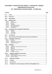
2.2 Inspect the condition of visible brake componentsNOTE:This includes the area underneath the vehicle.Reason for rejectionNOTE:a) Brake pipes, hoses and connections are damaged, severely deteriorated, not securely mounted, cracked, broken,kinked, crimped, damaged by heat or have visible signs of leakage, swelling or bulging (See Note1).For example the reinforcement fabric is exposed or the hose swells or bulges when the brakes are applied. Minorcracking or splits in the outer casing are not a reason for rejection but should be brought to the attention of the owner).b) where visible, any brake component is broken, excessively worn, leaking, contaminated or is not securelymounted.NOTE: Use manufacturer’s limits for assessing wear in componentsc) any hydraulic brake hose is of insufficient length to allow for the full range of steering and suspension movement,or is twisted.d) hydraulic lines are not constructed of approved material. (See note 2).e) any braided hydraulic brake hose that is not marked with the manufacturers name and compliance with a SAA,SAE, BS, JIS, DIN, ISO or ECE standards for flexible brake hoses.f) hydraulic pipes or hoses are not manufactured, repaired and marked to relevant Australian Standards (orequivalent). (See Note 3).g) hydraulic pipes are repaired by heating or welding (See Note 4).h) the level of brake fluid is below the minimum indicated level.i) where visible, the brake lining material, at any point, is worn to less than manufacturers limits or if the limits arenot known ;0.8mm above bonded shoe or pad mounting surface and level with the rivet or bolt heads on rivetedor bolted linings.j) it is evident that any power/vacuum assistance for the brakes is not operating or compressors, vacuum pumps,pulley belts are loose, cracked or worn.k) evidence of brake fluid leaking from any component, joint or seal.Note 2: The use of copper pipe for hydraulic brake pipe is not allowedTasmanian <strong>Inspection</strong> <strong>Manual</strong> for <strong>Light</strong> <strong>Vehicle</strong>sThe use of copper pipe for hydraulic brake pipe is not allowedHydraulic Brake Hoses fitted to vehicles that are required to comply withl) where ADR 42 applies, any brake hose is not marked with manufacturers name.ADR 7, 7/00 or 42/04 should be manufactured to SAE J1401 orNote 1: Threaded bosses used braking component mounting must have full depth thread engagement of at least the boltequivalent. Flares for Tubing should be in accordance with SAE J5336diameter.or equivalent.Note 3: Hydraulic Brake Hoses fitted to vehicles that are required to comply with ADR 7, 7/00 or 42/04 should bemanufactured to SAE J1401 or equivalent. Flares for Tubing should be in accordance with SAE J5336 or equivalent.Joining hydraulic brake pipes by brazing, silver soldering, etc. is notallowed. Note 4: Joining hydraulic brake pipes by brazing, silver soldering, etc. is not allowed.Figure 2 1 : Drum brake componentsDisc brake componentsigure 2-1 : Drum brake componentsDisc brake components18 <strong>Light</strong> <strong>Vehicle</strong> <strong>Inspection</strong> <strong>Manual</strong> Version 11, December 2013
2.3 Brake testing with a roller brake testerNOTE:This section should be read in conjunction with the equipment manufacturer’s instructionsUsing a roller brake tester, check the retardation forces on each wheel. Release all brakes, place transmission in “neutral”(not “park” for automatic transmission) and slowly apply a braking force until a maximum force is attained, or wheel slipoccurs.Reasons for rejectiona) there is more than 30% difference in the brake force between the wheels on any axle.b) the minimum brake force on any wheel is less than the performance requirement specified in Table 2.1.c) with the brakes released, the average brake drag is more than the performance requirement specified inTable 2.2.d) the parking brake does not give a reading, or the vehicle does not lift out of the roller.TYPE OF VEHICLEkN (minimum)Less thn 2.5 tonnes tare* 2.02.5 tonnes or over 3.0Table 2.1 : Minimum Brake ForceTYPE OF VEHICLELess thn 2.5 tonnes tarekN (minimum)0.5 drive axle0.25 other axle2.5 tonnes or over 1.0 drive axle0.5 other axleTable 2.2 : Maximum Brake DragNOTE:NOTE:On some light vehicles the brake force limit might not be reached as the vehicle will be lifted out of the rollers. Similarly,it might not be reached if a load proportioning valve is fitted to the rear axle. In both cases it is considered a pass if thebrake balance is within the specified limit.For further information on Brakes, refer to Appendix A ‘Brake drums and Discs’<strong>Light</strong> <strong>Vehicle</strong> <strong>Inspection</strong> <strong>Manual</strong>Version 11, December 2013 19
20 <strong>Light</strong> <strong>Vehicle</strong> <strong>Inspection</strong> <strong>Manual</strong> Version 11, December 2013
Section 3:Towing AttachmentsAustralian Design Rules relevant to this section:ADR 42 General safety requirementsADR 62 Mechanical connections between vehiclesOBJECTIVE: To ensure that all tow couplings and associated components are in a serviceable condition and that they providethe necessary load carrying capacity.3.1 Visually inspect the drawbar and its mounting on thevehicle bodyReasons for rejectiona) any towing attachment fitted to a vehicle, is not operational, not secure, or cracked, excessively worn, deformedor damaged in a way likely to cause failure.b) Tow bars, tow hooks, automatic pin type couplings and their attachments, if fitted to a vehicle, are not operational,not secure, or are cracked, excessively worn, deformed or damaged in a way likely to cause failure.c) any mounting bolts, fasteners or weld beads have advanced corrosion or are missing.d) where ADR 62 applies (vehicles manufactured after 1st July 1991), the towbar does not display the “name” or“trademark” of the manufacturer, the “make” and “model” shown on the identity plate of the vehicle for whichthe towbar is designed, and the towbars “maximum rated capacity”. (The “maximum rated capacity” must be the“ATM” in tonnes or maximum “coupling ‘D-value’ in kN for which the towbar is designed and must not exceedthe vehicle manufacturers rated towing capacity.e) where any part of the coupling or towbar is removable, the bolts, studs, nuts etc, fastening those parts do nothave a locking device such as a U-clip, split pin, spring washer, or nylon lock nut.f) Tow coupling tongue assemblies are not securely mounted to the tow bar assembly.g) The tow ball (if fitted) is not secure, is cracked or is excessively worn.h) The tow ball assembly (50 mm type) is not legibly and indelibly marked with the mark “50“ in characters not lessthan 5 mm high. (See Note 1).i) Safety chain/s or cables are not able to be connected or affixed in such a way that the safety chains/cables are notliable to accidental disconnection and are not readily detachable from the towing vehicle.j) Safety chain attachments are not affixed to a part of the towbar that is permanently attached to the vehicle.k) All electrical wiring, connectors, couplings, flexible pipes etc. associated with a device for coupling a trailer to amotor vehicle are not securely mounted and operational.l) A bicycle rack is fitted to the towbar and bicycles are not being carried.<strong>Light</strong> <strong>Vehicle</strong> <strong>Inspection</strong> <strong>Manual</strong>Version 11, December 2013 21
NOTES:(1) A 50 mm ball coupling is, generally, not acceptable for trailers which have an Aggregate Trailer Mass (ATM) in excess of2.3 tonnes.However, 50 mm ball couplings meeting the requirements of AS 4277.3 (Caravan and light trailer towing components -50 mm tow balls) are suitable for motor vehicles towing very light and light trailers of up to 3.5 tonnes ATM.Aggregate Trailer Mass (ATM) is the total mass of the laden trailer when carrying the maximum load recommended bythe manufacturer. This includes any mass imposed onto the drawing vehicle when the combination vehicle is resting on ahorizontal supporting plane.Note:For further information on Safety Chains, refer to Appendix B’ Safety chains for trailers.’22 <strong>Light</strong> <strong>Vehicle</strong> <strong>Inspection</strong> <strong>Manual</strong> Version 11, December 2013
Section 4:Steering and SuspensionAustralian Design Rules relevant to this section:ADR 10 Steering ColumnADR 42 General Safety RequirementsADR 43 <strong>Vehicle</strong> Configuration and DimensionsADR 69 Full Frontal Occupant ProtectionOBJECTIVE: To ensure that the steering and suspension is in good working order and allows the driver effective control ofthe vehicle.NOTE:To be registered in Australia a vehicle must usually have a steering control (right hand drive) to the right of, or inline with, the centreline of the vehicle. <strong>Vehicle</strong>s which are over 30 years of age may have left-hand-drive subject tocompliance with certain conditions.4.1 With the engine running, check the operation of thesteering by moving the steering wheel, or, on cycletype vehicles, the handleReasons for rejectiona) where a steering wheel is fitted, there is more than 50mm rotational free play.b) the steering wheel is not free from structural damage.c) Accessories fitted to steering wheels (padded hubs, covers etc.) are loose.d) Steering controls on a vehicle that was manufactured less than 30 years ago are to the left of (left hand drive)centre line of vehicle.e) Steering wheels fitted to light passenger vehicles manufactured on or after 1 January 1971 are not replaced by asteering wheel which complies with Australian Design Rule No. 10 .f) the steering wheel is not securely attached to the steering column.g) where steering linkages are fitted to cycle type vehicles, the rotational free play exceeds 10mm measured at theend of the handle bars.h) where ADR 69 applies, the steering wheel is not of the same specification as the one provided by the vehiclemanufacturer.i) where an supplementary restraint system (SRS) airbag is fitted, there is any evidence that an airbag or other SRSsystem is inoperative (check the indicator light, where fitted - this usually illuminates when the ignition is firstswitched “on” and extinguishes after the system passes a self-test).Note: The minimum diameter of any replacement steering wheel must not be less than 330mm. The replacement wheel mustbe designed in a similar manner to the original (e.g. padded centre hub and dished spokes).<strong>Light</strong> <strong>Vehicle</strong> <strong>Inspection</strong> <strong>Manual</strong>Version 11, December 2013 23
4.2 Visually inspect all steering components under thebonnet and under the vehicleNOTE:Take care with spring-loaded and rubber-bush joints. These components might be designed to have a certain amount ofallowable movement.Reasons for rejectionNOTE:a) any steering component is missing, cracked or broken or is worn beyond manufacturer’s limits.b) any steering component can be seen to have been repaired or modified by bending, heating or welding.Does not apply where an original component has been fitted by the manufacturer or repairs have been conducted tomanufacturer’s specifications.c) any nut, bolt or locking device is missing or insecure.d) Tie rod and drag link ends are not secured in both the rod and taper with fasteners suitably locked (e.g. split pins,lock-wire, tabs or self locking nuts).e) there is any movement on the spline between Pitman arm and the steering box or between any thread or taperedjoint.f) free play due to wear in any steering component exceeds manufacturer’s specification (if that specification is notknown, free play exceeds 3mm).g) any power steering componentTasmanianis leaking,<strong>Inspection</strong>damaged<strong>Manual</strong>or inoperative);for <strong>Light</strong> <strong>Vehicle</strong>sh) any manual or power steering componentry that is not securely mounted and free from excessive side or endplay, roughness, or binding.4.3 Examine i) any the power idler steering arm belts are loose, broken, frayed, missing, or cracked through to reinforcing plies.If fitted, attempt to move the idler arm in the direction of the pivot axis.4.3 Examine the idler armReason for rejectionIf fitted, attempt to move the idler arm in the direction of the pivot axis.a) The play at the end of the idler arm exceeds 8mm.Reason for rejectiona) The play at the end of the idler arm exceeds 8mm.Figure Figure 44-114.4 Visually inspect the suspension4.4 Visually inspect the suspensionReasons for rejectionReasons fora)rejectionany suspension component is broken, insecure, cracked, cut, missing, oil soaked, or can be seen to have beena) repaired any suspension or modified by component heating bending is broken, or welding insecure, or is worn cracked, beyond cut, manufacturers’ limits.b) anymissing,shock absorberor canorbestrutseenis inoperative;to have beenor isrepairedleaking fluid.or modified byheating bending or welding or is worn beyond manufacturers'c) any shock absorber or strut is not securely mounted.limits;d) any nut, bolt or locking device is missing or not secure.b) any shock absorber or strut is inoperative; or is leaking fluide) with the wheels raised, the vertical free play of any wheel exceeds 3mm.c) any shock absorber or strut is not securely mounted;d) any nut, bolt or locking device is missing or not secure;24 <strong>Light</strong> <strong>Vehicle</strong> e) with <strong>Inspection</strong> the wheels <strong>Manual</strong> raised, the vertical free play of any wheel exceedsVersion 11, December 20133mm;
Note:Superficial crazing is acceptable on rubber bushes. This is oftend) any nut, bolt or locking device is missing or not secure;e) with the wheels raised, the vertical free play of any wheel exceeds3mm;Figure 4 2Figure 4-2Tasmanian <strong>Inspection</strong> <strong>Manual</strong> for <strong>Light</strong> <strong>Vehicle</strong>sNOTE: Manufacturers’ tolerances take precedence over specified free play measurements when performing these checks.NOTE: Manufacturers' tolerances take precedence over specified freef) f) with with play the the measurements wheels wheels raised, raised, the when free the play free performing of play the of wheel these measured wheel checks. measured at the rim at exceeds the 6mm in total or 3mm from anycomponent.rim exceeds 6mm in total or 3mm from any component;Version 4 – 1 May 2009 Page 23Figure 4-3 4 3NOTE:Manufacturers’ Manufacturers' tolerances tolerances take precedence take precedence over specified over free specified play measurements free when performing these checks.g)g)anyplayaxlemeasurementscomponent, U-Bolt,whenspringperforminghangers, centretheseboltchecks.etc associated with the axle installation or performance iscracked, any axle loose, component, broken, missing U-Bolt, or worn spring outside hangers, of manufacturers centre bolt safe etc working limits.h) nuts associated do not fully with engage the axle the U installation Bolt thread. or performance is cracked,i)loose, broken, missing or worn outside of manufacturers safeany springs are cracked, broken, missing, displaced more than 10% of their width or in contact with wheels, brakesor working the frame. limits;j) h) air nuts bags do leak. not fully engage the U Bolt thread;k) i) any any raising/lowering springs are cracked, of eyebrow broken, height that missing, exceeds displaced 50mm from more original than manufacturer’s height.l)10% of their width or in contact with wheels, brakes or the frame;suspension heights are lowered or raised by more than one-third of the manufacturer’s bump stop clearance.m) j) A air vehicle bags does leak; not have a ground clearance equal to or more than:• k) 100 any mm raising within of one suspension metre of an that axle, exceeds and 50mm from original•manufacturer’s height;One thirtieth of the distance between the centres of adjacent axles at a midway point between them.l) suspension heights are lowered or raised by more than one-thirdNOTE: When measuring ground clearance, Tasmanian tyres, wheels and <strong>Inspection</strong> wheel hubs are <strong>Manual</strong> not taken into for consideration. <strong>Light</strong> <strong>Vehicle</strong>sof the manufacturer’s bump stop clearance;Note: Any suspension height modifications must comply with conditions set out in the National Code of Practice for <strong>Light</strong>m) A vehicle does not have a ground clearance equal to or more than:vehicle Construction and Modification – Section LS Tyres, Rims, Suspension and Steering.• 100 mm within one metre of an axle, and.• One thirtieth of the distance between the centres ofadjacent axles at a midway point between themNOTE:When measuring ground clearance, tyres, wheels and wheel hubsare not taken into consideration.Note:Figure 4 4 : Axle locating devicesAny suspension height modifications must comply with conditions set outNote: in the Superficial National crazing Code is of acceptable Practice on for rubber <strong>Light</strong> bushes. vehicle This Construction is often present and on rubber suspension components even when new.Modification – Section LS Tyres, Rims, Suspension and Steering.Note: For further information on Suspension, refer to Appendix C’ Suspension Modifications ’and Appendix D ‘Lift Kits’ andAppendix E ‘Ground clearances.’Figure <strong>Light</strong> <strong>Vehicle</strong> 4-4 : <strong>Inspection</strong> Axle locating <strong>Manual</strong> devicesVersion 11, December 2013 25
26 <strong>Light</strong> <strong>Vehicle</strong> <strong>Inspection</strong> <strong>Manual</strong> Version 11, December 2013
Section 5:Wheels and TyresAustralian Design Rules relevant to this section:ADR 23 Passenger Car TyresADR 42 General SafetyOBJECTIVE: To ensure that road wheels and tyres are of a suitable type and condition and that they provide the necessaryload carrying capacity, speed rating and control of the vehicle.5.1 Visually inspect the inside and outside of each roadwheelReasons for rejectiona) any wheel or rim is cracked, has pieces of casting missing, or is buckled, shows signs of welding; signs of elongationof stud holes or redrilling of stud holes.b) the wheel nut must have a thread engagement length at least equal to the thread diameter or the fitting of thewheel nut does not match the taper of the wheel stud hole).c) any hub has missing or broken wheel mounting nuts, studs or bolts.d) any spoked wheel has any missing, loose, broken, bent or cracked spokes.e) the tyre or rim makes contact with or fouls any component at any point over the full range of suspension travelor steering movement.f) Wheels/rims are not of an approved type and construction.g) Spacer plates are used between hub and wheels, except where fitted by the vehicle manufacturer.5.2 Visually inspect each road tyreReasons for rejectiona) Any road tyre fitted to the vehicle is not a pneumatic tyre.b) the tyre has less than 1.5mm tread depth in a continuous band around the circumference on the surfaces whichnormally contacts the road.c) the tyre has deep cuts, bulges, exposed cords or other signs of carcass failure on either the side wall or treadsurface.d) tyres fitted to rims on an axle or axle group are not the same size.e) tyres are not compatible with the rim to which they are fitted and not of a type suitable for normal road use(space-saver wheels excepted).f) the tyre has been re-grooved (except where indicated on the sidewall that the tyres are suitable for re-grooving).g) any retreaded tyre fitted to the vehicle is not marked with the name or identification of the retreader and speedrating of the tyre.h) dual tyres contact each other.i) tyre load ratings are less than the minimum ratings specified originally by the vehicle manufacturer.j) for a car or car derivative, the maximum tyre width is more than 1.3 times larger than the vehicle manufacturer’swidest optional tyre width (See Note 1).k) a tyre that exceeds the maximum width of the vehicle.<strong>Light</strong> <strong>Vehicle</strong> <strong>Inspection</strong> <strong>Manual</strong>Version 11, December 2013 27
l) for a passenger car with 4 or more wheels manufactured after 1972, the speed rating of all tyres, when firstmanufactured, is not at least 180 km/h unless a lower rating has been specified.m) for a passenger car, the tyre/s have a rolling diameter that is 15 mm larger or 26 mm smaller than that of any tyredesignated by the vehicle manufacturer for that model.n) for a off road passenger or commercial vehicle, the tyre/s have a rolling diameter that is 50 mm larger or 26 mmsmaller than that of any tyre designated by the vehicle manufacturer for that model.o) alteration of tyres that effect the correct operation of the speedometerp) A symmetrical (directional) tyre fitted to the vehicle in the wrong direction.Note 1: Where the manufacturer offers the option of a wider track measurement (e.g. where wider wheels are optional), themaximum allowable track will be the maximum wheel track offered by the manufacturer or the track of the standardvehicle plus 25 mm for a car or car derivative.Note 2: Retreads must comply with Australian Standards AS 1973-1993 for speed and construction5.3 Tyres on Four Wheel Drive/Off Road <strong>Vehicle</strong>s:Reasons for rejection:a) For an off-road passenger vehicle (four wheel drive) fitted with front and rear beam axles, the maximum tyrewidth is more than 1.5 times larger than the vehicle manufacturer’s widest optional tyre width.b) The tyre width of the narrowest tyre fitted to a vehicle is less than 70 percent of the width of the largest tyrefitted or less than the manufacturer’s narrowest optional tyre and rim as indicated on the manufacturer’s tyreplacard.c) Where wider wheels and tyres are fitted which comply with both legislative and the manufacturer’s specificationsor are approved by the manufacturer and protrude beyond the vehicles extremities, additional flared mudguardsare not fitted. (See Notes 1 and 2).d) For a vehicle with beam axles the wheel track is increased by more than 50 mm over the manufacturer’s standardtrack measurement or vehicles without a beam axle where the wheel track is increased by more than 25 mmover the manufacturers standard track measurement. (See Note 1).e) For a off road vehicle with 4 or more wheels manufactured after 1972, the speed rating of all the tyres when firstmanufactured is not at least 140 km/h, unless a lower rating has been specified.Note 1: Where the manufacturer offers the option of a wider track measurement (e.g. where wider wheels are optional), themaximum allowable track will be the maximum wheel track offered by the manufacturer or the track of the standardvehicle plus 25 mm, or 50 mm for an off-road or commercial vehicle, fitted with front and rear beam axles.Note 2: Maximum regulation dimensional limits must not be exceeded.5.4 Measure the wheel track, where modified fromstandard, taking measurement from the centre ofthe tyresReason for rejectiona) The vehicle manufacturer’s specified wheel track measurement for the vehicle is exceeded by more than is currentlyapproved by State/Territory for specific vehicle types.Note:For further information on retreaded tyres, refer to Appendix F ’Retreaded tyres.’28 <strong>Light</strong> <strong>Vehicle</strong> <strong>Inspection</strong> <strong>Manual</strong> Version 11, December 2013
Section 6:Body ConditionADRs applicable to this section:ADR 2 Sliding door latches and hingesADR 10 Steering columnADR 11 Internal Sun visorADR 18 InstrumentationADR 21 Instrument panelADR 25 Anti-theft lockADR 29 Side door strengthADR 34 Child restraint anchorages and child restraint anchor fittingsADR 42 General safety requirementsADR 43 <strong>Vehicle</strong> configuration and dimensionsADR 69 Full Frontal Impact Occupant ProtectionOBJECTIVE: To ensure the vehicle body is free of protrusions, structurally sound and free from any defects or additionalfittings that are likely to increase the risk of bodily injury to any occupant and other road users.6.1 Check the operation of all doors, door locks andlatches and the bonnet lock and latchesReason for rejectiona) any inside or outside door latch, bonnet, tilt cab, boot lid, hatch and removable covers (including safety catches, asapplicable) are not securely fitted, mounted and operating correctly.b) Door fastenings, hinges, inside and outside door control handles (as applicable) are not fitted, secure and operatingcorrectly.c) any bonnet or similar panel which covers the engine, luggage space or battery compartment and which is forwardof the windscreen, does not have a device to secure the panel in the closed position.d) any bonnet or similar panel which opens from the front (that is, the hinges are at the back) and which, whenopened, would obstruct the driver’s view through the windscreen, does not have a primary and secondary securingdevice.e) any hinges, or slides for doors, tailgates, side gates, hatches or compartment covers are damaged or worn andlikely not to prevent load or passenger from falling off.6.2 Visually inspect the windscreen and front sidewindowsOBJECTIVE: To ensure that the windscreen, windows and associated components are in such a condition that the driverhas a clear field of vision at all times under the normal range of climatic conditions.<strong>Light</strong> <strong>Vehicle</strong> <strong>Inspection</strong> <strong>Manual</strong>Version 11, December 2013 29
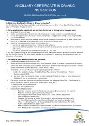
Reason for rejectionNote:a) The area of windscreen from the centre of the vehicle in front of the driver has cracks or is deteriorated to theextent it that interferes with the driver’s view.b) The wiped area of the windscreen in front of and on the same side of the vehicle as the driver has.1) damage (such as scoring, sandblasting or severe discolouration) that interferes with the driver’s view.2) any bulls-eye or star fracture that exceeds 16 mm in diameter, or any two (2) of the following.i) hairline crack up to 30 mm long.ii) a crack from the edge of the windscreen up to 75 mm long.Grooves in windscreens that are designed specifically to clean the wiper blades are not regarded as damage unless theyaffect the driver’s view. Approved grooving is usually identified by the installer.c) Any cracks in a laminated windscreen penetrate more than one layer of glass or are more than 150 mm long.d) Any glazing used in any motor vehicle is not safety glass (except a caravan) and where ADR 8 applies, the glassdoes not display an identification mark or symbol.e) Tint films are not free of bubbles, scratches or other defects that significantly affect the driver’s vision.f) Glazing is loose in its frame or cracked to the extent that sharp edges are exposed.g) Glazing, other than the windscreen, that is necessary for the driver to see the road is discoloured, obscured, badlyscratched, sandblasted or fractured to the extent that it interferes with the driver’s view.h) Items that obscure the driver’s view are placed in Area A or the corresponding area on the other side of thewindscreen.i) At least half the number of windows must be capable of being opened or the vehicle must be provided with analternative method Tasmanian of ventilation. <strong>Inspection</strong> <strong>Manual</strong> for <strong>Light</strong> <strong>Vehicle</strong>sj) Windscreens are removed and not replaced.EXCEPTION: EXCEPTION: Any Any two two of of the the following three types of of damage damage are are acceptable: acceptable:Figure 6 1Figure 6-1Note: This rule applies to windscreens repaired with clear resins. After repair, there must be no visible damage beyond theNOTE: This limits rule given applies above. to windscreens repaired with clear resins. Afterrepair, there must be no visible damage beyond the limits givenabove.6.3 Test the light transmittance level of the windscreen,side and rear windows3 Test the light transmittance level of the windscreen, sided rear windowsNote: (i) This section should be read in conjunction with the light meter manufacturers’ instructions.NOTE: (i) This section should be read in conjunction with the lightmeter (ii) The manufacturers' light meter may instructions. have up to a 5% measuring inaccuracy. A vehicle may be accepted if the readings are up to 5%lower than the minimum light transmittance.(ii) The light meter may have up to a 5% measuring inaccuracy.Reasons for rejectionA vehicle may be accepted if the readings are up to 5% lower thana) the Any minimum windscreen light glazing transmittance. has any coating which reduces its light transmittance other than in the area described intable below.easons for rejection30 a) <strong>Light</strong> <strong>Vehicle</strong> Any windscreen <strong>Inspection</strong> <strong>Manual</strong> glazing has any coating which reduces its lightVersion 11, December 2013transmittance other than in the area described in table below;
) Tint films are not free of bubbles, scratches or other defects that significantly affect the driver’s vision.c) The visible light transmittance of any glazing (including any applied film) is less than that detailed in the table below.Tasmanian <strong>Inspection</strong> <strong>Manual</strong> for <strong>Light</strong> <strong>Vehicle</strong>sd) Tinted film has more reflective reflection (metallic or mirror like) than the untreated glass.GlazingMinimum <strong>Light</strong>TransmittanceWindscreen 75% 70%All other windows 35% 30%<strong>Vehicle</strong>s NOT TO BEREJECTED until meterreadings are LESS thanNo limit for windows to the rear of the driver ifthe vehicle is a bus, stretch limousine,ambulance or hearse.No limit for windows with glazing or coatingfitted before 1 October 1996 behind the rear ofthe driver’s seat of the vehicleNo limit for windows with glazing or coatingadjacent to the rear of an area of a motorvehicle designed and built to carry goods.No limit for a tinted or opaque band at the top ofthe windscreen, provided it is above the arcswept by the windscreen wipers, or the upper10% of the windscreen, whichever is the lesser.Note: For further information on Windscreens, refer toAppendix G’ Windscreen Damage and Repair’Note:For further information on Windscreens, refer to Appendix G’ Windscreen Damage and Repair’6.4 Visually inspect body panels, chassis and sub frame for6.4 dangerous Visually inspect protrusions body panels, chassis and and rust sub frame forReasons dangerous for rejection protrusions and rusta) exterior body work and fittings have sharp edges due to rusted panels or body damage, or protrusions of anyReasons after for market rejection object or fittings, not technically essential to the operation of the vehicle, which protrudes from anypart of the a) vehicle exterior that could body cause work injury and fittings to a person have coming sharp into edges contact due with to rusted the vehicle.b) any structural member panels or such body as a damage, sub frame, or floor protrusions panel, door of sill, any seat after or seat market belt anchorage, object is cracked or hasadvanced rust. or fittings, not technically essential to the operation of the vehicle,c) Unrepaired damagewhichorprotrudesmodificationsfromaffectingany parttheofstructuralthe vehicleintegritythatofcouldthe vehicle.cause injuryto a person coming into contact with the vehicle;d) Any evidence that body has been cut and joined.b) any structural member such as a sub frame, floor panel, door sill,e) where ADR 29 applies, the doors of a vehicle have advanced rust.seat or seat belt anchorage, is cracked or has advanced rust;f) chassis frame members or supporting members are cracked, loose, sagging or broken.c) Unrepaired damage or modifications affecting the structuralg) frame members in load areas are missing, damaged or unsecured.integrity of the vehicle;h) tilting cabin or tray latches do not hold the cabin or tray securely in the operating position.d) Any evidence that body has been cut and joined;i) a bull bar is not approved by the manufacture to comply with the requirements of ADR 69 and supplementaryrestraint e) system where (SRS) air ADR bag 29 compatible applies, where the doors required. of a vehicle have advanced rust;Note: Refer to Appendixf) chassisO modificationsframe membersbrochure onorbullsupportingbarsmembers are cracked,loose, sagging or broken;j) Any repairs carried out do not retain the original strength of the component/section.g) frame members in load areas are missing, damaged or unsecured;k) any object or fitting, not technically essential to such vehicle, which protrudes from any part of the vehicle so thatit is likely to increase the risk of bodily injury to any person.l) Any component that adversely affects the safety of the vehicle, and in particular, obscures the drivers view.Version m) Tow 4 – bar 1 May mounted 2009 bicycle carrying racks or similar devices are not removed when not in Page use, unless 32 specificallydesigned to fold away.<strong>Light</strong> <strong>Vehicle</strong> <strong>Inspection</strong> <strong>Manual</strong>Version 11, December 2013 31
first line delete “August 2011” and insert “June 2012” Administration of the manual Page 11 – Version control At the end of the first line delete “August 2011” and insert “June 2012” n) A bicycle and the carrier assembly (or similar, when fitted) obscures any compulsory lighting or the number plate.transmittance level of the windscreen side and rear windows .3 c) insert the following: o) Permanently mounted fishing rod holders, driving lights and fog lights protrude above or forward of the top railor leading edge of the bumper or bull bar.SECTION 6 6.3 test the light transmittance level of the windscreen side and rear windows Page 31 – after 6.3 c) insert the following: p) Temporarily attached rod holders are not removed or adjusted so as to meet the above requirement when notin use.s more reflective reflection (metallic or mirror like) than the untreated glass. 6.5 Dimensionsd) Tinted film has more reflective reflection (metallic or mirror like) than the untreated glass. ect body Reason panels, for rejection chassis and sub frame for dangerous protrusions and rust 4 and its contents a) The width insert of the vehicle a new exceeds 6.5 2.5 metres below and amend all section numbers thereafter6.4 Visually inspect body panels, chassis and sub frame for dangerous protrusions and rust b) The height of the vehicle exceeds 4.3 metresPage 32-‐ after 6.4 and its contents insert a new 6.5 below and amend all section numbers therfor c) section The length 6 of the vehicle exceeds 12.5 metres6.5 Rear overhang g tion 6.6 Rear overhangReason for rejectionng (RO) of the vehicle exceeds the lesser of the following two measurements: eelbase or -‐3.7 metres. ng of a trailer exceeds the lesser of the following measurements: he load-‐carrying area forward of the rear overhang line or 3.7 metres. Reason for rejection a) The rear overhang (RO) of the vehicle exceeds the lesser of the following two measurements: a) The rear overhang (RO) of the vehicle exceeds the lesser of the following two measurements:-‐ 60% of the wheelbase or -‐3.7 metres. - 60% of the wheelbase or -3.7 metres.b) The rear overhang of a trailer exceeds the lesser of the following measurements: b) The rear overhang of a trailer exceeds the lesser of the following measurements:-‐ length of the load-‐carrying area forward of the rear overhang line or 3.7 metres. - The length of the load-carrying area forward of the rear overhang line or 3.7 metres.ROH Wheelbase ROH 6.7SECTIONInspect 8 the wheel arches/mudguards and mudflaps,with the wheels in the “straight ahead” position8.7 Visually inspect the headlights Page 40 -‐ after 8.7 d insert the following e) The headlight lens shows deterioration reducing the effectiveness of the headlight from initReasons for rejectiona) Mudguards are not fitted to all wheels of passenger and goods type vehicles.b) The mudguard and/or bodywork covering any wheel is not at least as wide as the tyre over the arc betweenmanufacture.points Tasmanian A and <strong>Inspection</strong> B in the diagram. <strong>Manual</strong> for <strong>Light</strong> <strong>Vehicle</strong>sPoint C (being on the rear edge of the mudguard/mudflap/ bodywork and in line with the centreline of the tyre -Point C (being on see the diagram) rear edge is more of the than mudguard/mudflap/ 150m in vertical bodywork distance and above the centre of the wheel. NOTE: Points along the rearSECTION 10 in line with the centreline edge which of are the inboard tyre - see of diagram) Point C is should more also than meet 150m this in requirement. A mudflap which is too flexible to maintain itsposition during normal driving conditions should be disregarded for this check.ct the headlights .7 d insert the following lens shows deterioration reducing the effectiveness of the headlight from initial 10.10 Visually inspect shut of devices, converters (vaporiser regulators), fuel selectors and air/mixers. Page 49-‐ After 10.10 i) insert the following i) Any gas leaks. pect shut of devices, converters (vaporiser regulators), fuel selectors and air/gas .10 i) insert the following 32 <strong>Light</strong> <strong>Vehicle</strong> <strong>Inspection</strong> <strong>Manual</strong>vertical distance above the centre of the wheel. NOTE: Points along the 1 Version 11, December 2013rear edge which are inboard of Point C should also meet thisrequirement. A mudflap which is too flexible to maintain its position
c) For a passenger car the lower edge of the mudflap is more than 230 mm above ground level when parked onlevel ground.d) For a vehicle with off road capabilities the lower edge of the mudflap in more than 300 mm above ground levelwhen parked on level ground.Note:For further information on Mudguard requirements, refer to Appendix H’ Mudgaurd and Mudflap Requirements’.6.8 Visually inspect rear vision mirrorsOBJECTIVE: To ensure that the mirrors and associated components are in such a condition that the driver has a clear fieldof vision by reflection of the road behind the vehicle and any following or overtaking vehicles at all times under the normalrange of climatic conditions.Reasons for rejectiona) rear vision mirrors are cracked, loss of reflectivity, missing, or do not provide a clear view of the road to the rearof the vehicle.b) where there is no effective rear vision provided by the internal rear vision mirror, the vehicle does not have anexternal rear vision mirror fitted to each side.c) any light commercial vehicle (except a station wagon) is not fitted with an external rear vision mirror on eachside of the vehicle.d) mirrors are not securely mounted.e) mirrors are obscured.f) The right side rear vision mirror fitted to a vehicle over 3.5 tonnes Gross <strong>Vehicle</strong> Mass (GVM) is not fitted with aflat reflecting surface.6.9 Visually inspect and check the operation of thewindscreen wipers and windscreen washersReasons for rejectiona) The windscreen wipers are not operational at all speeds and do not return to their normal parked position.b) windscreen wiper blades are missing, cracked, curled, frayed or torn.c) windscreen washers do not work or are not correctly aimed onto the windscreen.g) the windscreen washer is not able to be operated from a normal driving position.6.10 Check the operation of the hornReasons for rejectiona) A warning device (horn) is not fitted and operational and the tone is not of a single pitch.b) A warning device (horn) is not clearly audible and the actuating mechanism is not located within the reach of thedriver in the normal seated position.6.11 Visually inspect the front and rear number platesReasons for rejectiona) number plate is obscured, for example by a towing attachment goose neck, or tow ball.b) number plate covers are tinted, reflective, rounded, or bubble like.c) the number plate is damaged or faded to the extent that the registration number is not legible from a distance oftwenty metres.d) number plate has a substance applied to the reflective surface that would prevent the production of a clearphotograph.e) the registration (number) plate is not issued or approved by the State or Territory Road <strong>Transport</strong> Authority.f) The number plate is mounted more than 1300mm from the ground.<strong>Light</strong> <strong>Vehicle</strong> <strong>Inspection</strong> <strong>Manual</strong>Version 11, December 2013 33
g) The number plate does not face the front or rear in an upright position parallel to the vehicles axles.h) Characters in the number plate are not clearly visible from a distance of 20 metres at any point within an arc of45 degrees from the surface of the number plate above or to either side of the vehicle.6.12 Where ADR 25 applies, check the operation of theanti-theft/steering lockReasons for rejectiona) the ignition key can be removed in any position except the “anti-theft” (lock) position.b) when engaged, the anti-theft lock does not prevent at least one of the following actions.• steering the vehicle.• engaging the forward drive gears.• release of the brakes.6.13 Where ADR 42 applies, check the operation of thewindscreen demisterReasons for rejectiona) A motor vehicle that is fitted with a windscreen other than a motorcycle that is not fitted with a device capableof removing condensed moisture from the inside of the windscreen.6.14 SpeedometerReason for rejectiona) speedometer is not operational.b) speedometer indicator values are not legible.c) The speedometer is not calibrated in km/h and the vehicle was manufactured on or after 1 July 1988.34 <strong>Light</strong> <strong>Vehicle</strong> <strong>Inspection</strong> <strong>Manual</strong> Version 11, December 2013
Section 7:Seats and SeatbeltsAustralian Design Rules relevant to this section:ADR 3 Seat anchoragesADR 4 SeatbeltsADR 5 Anchorages for seatbelts and child restraintsADR 22 Head restraintsADR 34 Child restraint anchorages and child restraint anchor fittingsADR 69 Full frontal impact occupant protectionOBJECTIVE: To ensure that all seating and restraints fitted to the vehicle provide a comfortable and secure position for thedriver to control the vehicle and control the deceleration of all vehicle occupants7.1 Check seatsReasons for rejectiona) Seat frames or attaching points are loose, cracked, broken or have fasteners missing.b) Any seat has an exposed sharp edge or other parts that protrude due to damage.c) Seat cushions and backrests are not fitted.d) A seat slide or other seat control used for adjustment of a seating position is not operational and does not holdany selected position allowed for in the mechanism’s design.e) Any reduction, increase, or modification in seating is not certified by an approved modification plate.f) The fittmant of non original equipment manufacturer seats not certified by an approved modification plate.g) Any passenger car, forward control vehicle passenger vehicle or off road passenger vehicle or light omnibus (up to12 seats) that was built after 1 July 1988 is not fitted with head restraints to each front outboard seating position.h) Any light goods vehicle (GVM not exceeding 3.5 t) manufactured after 1 July 1996 is not fitted with headrestraints to the front outboard seating positions.i) Unapproved seat covers fitted to seats that have Supplementary Restraint System (SRS) fitted7.2 Check the operation of seats, seat belts, buckles andother restraints, and inspect webbing and metal stalksReasons for rejectiona) Seat belt assemblies are not securely attached to the respective anchorage point and show signs of distortion,cracks, fractures or other damage likely to cause failure.b) Any retractor, locking mechanism, buckle, tongue or adjustment device is inoperative.c) any metal stalk is missing or has broken wires.d) in other than ADR 34 vehicles, where fitted, child restraint attachment points are loose or cracked.e) where ADR 34 applies, child restraint attachment points are loose, cracked or missing.Non retractable seat belts do not have sufficient adjustment to allow effective use of the belts and do not maintain theadjusted positions.g)Where ADR 69 applies, the seatbelt warning light does not operate for a minimum of 10 secondswhen the ignition is switched to the on or start position.<strong>Light</strong> <strong>Vehicle</strong> <strong>Inspection</strong> <strong>Manual</strong>Version 11, December 2013 35
f) Seatbelt webbing that is.1. Damaged.2. Frayed.3. Stretched.4. Tied in a knot.5. Twisted.6. Split.7. Torn.8. Cut.9. Altered or modified.10. Severely deteriorated.11. Burnt.12. Not correctly and firmly secured to each end fitting.13. Webbing/stitching becoming detached at any point.NOTE:Note:Discolouring alone is not a reason for rejection.For further information on Seatbelts, refer to Appendix I’ Australian Design Rule – Seatbelt Requirements.’36 <strong>Light</strong> <strong>Vehicle</strong> <strong>Inspection</strong> <strong>Manual</strong> Version 11, December 2013
Section 8:<strong>Light</strong>ingAustralian Design Rules relevant to this section:ADR 1 Reversing lamps.ADR 6 Direction indicator lampsADR 13 Installation of lighting on other than L group vehiclesADR 19 Installation of lighting on L group vehiclesADR 45 <strong>Light</strong>ing not covered by ECE regulationsADR 46 Head lampsADR 47 Reflex reflectorsADR 48 Rear registration plate illuminating devicesADR 49 Front and rear position (side) lamps, stop lamps and end-outline marker LampsADR 51 Filament globesADR 60 Centre high mounted stop lampsOBJECTIVE: To ensure that all lights, reflectors and other electrical lighting components as required by prescribed standardsare operational.8.1 Visually inspect the compulsory reflectors fitted to therear of the vehicleReason for rejectiona) Red reflector(s) are damaged, discoloured or missing (note: reflectors may be incorporated in the lampassembly).8.2 Visually inspect and check the operation of all lightsfitted to the vehicleReasons for rejectiona) any of the following lights do not work or has incorrect colour.(i) headlight (high/low beam) (white)front park or side lights (white)tail lights (red)brake light(s) (red)turn signal indicator lights (yellow)clearance lights (trucks and cycle type vehicles only) (front: yellow/white, side: yellow, rear: yellow/red)number plate light (white).b) any rear light other than a reversing light is in a condition or damaged to the extent that white light shows to therear of the vehicle.c) any yellow clearance light or front turn signal is damaged so that it shows white light.<strong>Light</strong> <strong>Vehicle</strong> <strong>Inspection</strong> <strong>Manual</strong>Version 11, December 2013 37
d) the number plate light is not directing light onto the surface of the rear number plate.e) Any optional lights or reflectors interfere with any compulsory lights or reflectors.f) Additional lighting (fitted as accessories) is fitted in such a way that their operation will impair the operation ofstatutory lighting, and contravene prescribed standards.g) lights as follows are not fitted to pre 3rd Edition ADR vehicles (passenger and light goods vehicles and lightomnibuses) (dimensions at centre of lights).At front of vehicle:(1) 2 White Main beam (high beam) headlights, min 500mm off ground, with min separation of 600mm.(2) 2 White Dipped beam headlights, min 500mm and max 1400mm off ground, min 600mm separation.(3) 2 White Park lights, min 500mm off ground, max 510mm inboard of vehicle side, wired to remain “on” withheadlights if vehicle built after 1969. Note: vehicles manufactured prior to June 1953 are not required to be fittedwith park lights.(4) 2 Yellow turn signal indicators (7/73 onwards, pre 7/73 may be white), min 350mm and max 1500mm fromthe ground (if 1500mm not practicable 2100mm), min 400mm separation if vehicle less than 1300mm wide or600mm if vehicle over 1300mm wide, max 500mm inboard of vehicle side; Note: vehicles manufactured prior toAugust 1966 are not required to be fitted with directional indicators.(5) 2 Yellow or White clearance lights (where vehicle is over 2.2m wide), min 750mm above headlights, max 400mminboard of side of vehicle; Note front clearance lights must not be fitted to a vehicle that is less than 1.8 metresin width.(6) 2 Hazard warning lights (10/91 onwards), incorporated with turn signal indicators.(7) Optional White or yellow fog lights, mounted no higher than the headlights wired through park lights on aseparate switch, may also operate when main and/or dipped beam headlights are illuminated.(8) Additional main beam headlights (driving lights) are not fitted in pairs to a maximum of 4 lights.(9) Additional Main beam headlights (driving lights) are not wired so that they extinguish when switched to dippedbeam, park light or off positions.(10) Additional Main beam headlights (driving lights) are not forward facing.(11) Additional Main beam headlights (driving lights) are mounted in such a way that they are a dangerous protrusionor interfere with the drivers vision.(12) Additional Main beam headlights (driving lights) are mounted in such a way that when on they reflect light backto the driving position.At Side of vehicle:1) 2 Yellow to front, red to rear side marker lamps (where vehicle is more than 2.2m wide and/or 7.5m long), min600mm and max 1500mm off ground, max 300 mm from rear of vehicle.At Rear of vehicle:1) 2 (1 prior to 1959) Red tail lights, max 1500mm off ground, min 600mm apart, max 400mm inboard of side ofvehicle (single light located in centre or right side of vehicle).2) 2 Red reflectors, max 1500mm off ground, max 400mm (250mm if vehicle more than 2.2m wide) inboard of sideof vehicle.3) 2 (8/72 onwards) white or yellow reverse lights, max 1200mm off ground.4) White registration plate lamp/s, to illuminate registration plate.5) 2 (1 prior to 1959) Red stop lights, min 300mm and max 1500mm off ground (single light to be in centre or onright side of vehicle).6) 2 Yellow (red permitted prior to 7/73) turn signal indicators, min 350mm and max 1500mm off ground, min600mm separation. Note: vehicles manufactured prior to August 1966 are not required to be fitted withdirectional indicators.7) 2 Hazard warning lights (10/91 onwards), incorporated with turn signal indicators.38 <strong>Light</strong> <strong>Vehicle</strong> <strong>Inspection</strong> <strong>Manual</strong> Version 11, December 2013
8.3 Visually inspect and check condition of all lights fittedto the vehicleReasons for rejection:a) Any light is not clearly visible under all normal conditions and of a consistent intensity, or are affected by dirtylenses or poor electrical contact.b) Reflector surfaces are not free of tarnish or other damage, which could reduce the intensity of high or low beam.c) Headlights are not correctly focused.d) Lenses and light reflectors are not securely mounted, are faded or discolored and are not free from cracks, holes,or other damage which would allow the entry of moisture or dirt to impair the efficiency of the light or reflector.8.4 Visually inspect and check light switch operationReasons for rejection:a) The headlight high beam tell tale indicator light is not operating.b) Additional headlights (driving lights) do not operate in conjunction with the high beam circuit, and are not fittedwith an independent on/off switch.c) The high/low headlight switch and turn signal switch is not readily operable by the driver from the driving positionand, if fitted as original equipment by the manufacturer, is not self-cancelling.d) The turn signal operation is not indicated by means of a visible and/or audible telltale.e) The reverse light (if applicable) operates other than when reverse gear is selected.f) Any fog lights fitted can not be switched independently of the main or dipped beam headlamps.g) Fog light switch (after September 1991) does not have a tell tale indicator to indicate that the switch is on.8.5 Visually inspect front and rear lights for the presenceof tinted coversReasons for rejectiona) any light has a tinted cover over it, or any tinting applied to it.b) there is any opaque cover over a headlight which cannot be readily removed without the use of tools.8.6 Using a headlight tester, check the aim of theheadlightsReasons for rejectiona) the aim of the headlight is adjusted such that, when on high beam and measured at an effective distance of 8m,the projected centre of the beam is to the right of the headlight centre and/or is above the headlight centre.b) when measured at an effective distance of 8m, any part of the top edge of the high intensity portion of the lowbeam pattern is above and/or to the right of the centreline of the headlight.NOTES:In the region above and to the right of the centreline of the headlight the luminous intensity must not exceed 437cd.The portion of the beam to the left of the centreline of the light may extend above the height of the centreline of the headlight.The “centreline of the headlight” passes through the centre of the globe filament, or equivalent.<strong>Light</strong> <strong>Vehicle</strong> <strong>Inspection</strong> <strong>Manual</strong>Version 11, December 2013 39
8.7 Visually inspect the headlightsReasons for rejectiona) headlight reflector is tarnished or peeling to the extent that headlight performance is impaired.b) headlight lens is incomplete.c) headlight assembly is not secured.d) headlight is water damaged or has incorrect beam pattern.e) the headlight lens shows deterioration reducing the effectiveness of the headlight from initial manufacture.Note:For further information on lighting requirements, refer to Appendix J’ <strong>Light</strong>ing Standards’ and Appendix K ‘Headlamptesting Screens’.40 <strong>Light</strong> <strong>Vehicle</strong> <strong>Inspection</strong> <strong>Manual</strong> Version 11, December 2013
Section 9:Engine Compartment & DrivelineADRs applicable to this section:ADR 42 General safety requirementsADR 79 Emission Control for light vehiclesADR 80 Emission control for Heavy <strong>Vehicle</strong>sADR 83 External NoiseOBJECTIVE: To ensure that engine and driveline components are compliant with the regulations and operate in a safe manner.9.1 Visually inspect the engine, transmission and drivelinefor oil/fluid leaks.Reasons for rejectiona) oil is leaking from the engine, gearbox, differential, or from any joint or seal onto any of the following.1. brake friction surfaces.2. the exhaust system.3. oil or fluid dripping onto the road surface, at a rate of more than one drop every 30 seconds.b) Evidence of oil or fluid leaking from any brake or power steering component.9.2 Visually inspect engine, transmission and drivelinecomponentsReason for rejection:a) any engine or transmission mounting is cracked or not secured.b) rubber components are severely perished, broken or deteriorated.c) fasteners on couplings in the driveline are cracked, loose or missing.d) any transmission drive shaft is bent, damaged, loose or noticeably misaligned.e) any universal or constant velocity joint has excessive wear, is misaligned, seized, is not securely attached, or has adamaged or missing boot.f) where an automatic transmission is fitted, the engine can be started in any gear position other than neutral orpark (ensure that brakes are applied during this test).g) any modifications to engine, transmission and driveline components that does not have modification approvalNOTE: For further information on modifications, refer to Appendix O modification brochure9.3 Visually inspect the electrical systemReasons for rejection:a) A battery (s) is not secured in a cradle or carrier using hold down clamps, is cracked, leaking or has missing caps.b) A battery mounted in the interior of a bus is mounted to allow acid or fumes to come into contact withpassengers or goods.<strong>Light</strong> <strong>Vehicle</strong> <strong>Inspection</strong> <strong>Manual</strong>Version 11, December 2013 41
c) Electrical wiring is not securely mounted and insulated, is exposed to excessive heat.d) Wiring not supported at 600 mm or less intervals.e) Chafing or located in such a way that would cause danger to the operation of the vehicle.f) Electrical wiring hinders driver or passenger movement.g) Any electrical wiring or connector that is corroded damaged, not insulated or securely fastened so that it couldbe damaged.h) Electrical wiring is unprotected from abrasion.i) Wiring is exposed to excessive heat.j) Wiring is in contact, or can contact moving parts.9.4 Visually inspect the exhaust systemReasons for rejectiona) any component of the exhaust system that is cracked, or not securely mounted.b) the exhaust system is not fitted with an effective silencing device through which all of the vehicles exhaust pass.c) exhaust pipe outlet is not rearward of all side passenger doors and opening windows and more than 40 mmbeyond any floor joint that is not continuously sealed or welded.d) Exhaust pipe outlet discharges to the left-hand side of the vehicle.e) there is any leak in the exhaust system, excluding manufacturers’ drain holes in the mufflers.f) exhaust outlet does not extend to the outline of the vehicle body..g) the exhaust system fouls any part of the steering, suspension, brake or fuel system.h) the exhaust does not have a ground clearance equal to or more than 100 mm.i) emission control equipment (where required) missing or not operative.j) the engine lets out sparks, flames, excessive gases, oil or fuel residue.k) for a vehicle manufactured after 1930 and propelled by an internal combustion engine, the vehicle emits visibleemissions for a continuous period of more than 10 seconds.NOTE:A vehicle should not be rejected for emissions that are visible only because of heat or the condensation of water vapour.9.5 Visually inspect the fuel systemReason for rejectiona) there is any leakage from the fuel system.b) any part of the fuel system is insecure or damaged so that there is a risk of a fuel leak.c) the fuel cap is missing, insecure, or of the incorrect type.d) the air cleaner is not fitted.e) Engine speed does not return to normal idle position upon release of the accelerator pedal or throttle control.f) Nitrous oxide injection equipment is fitted irrespective of its operational ability.g) Multiple and/or replacement carburetors fitted to any motor vehicle do not continue to comply with theemission requirements of the Australian Design Rules applicable at the time of the vehicle’s manufacture.42 <strong>Light</strong> <strong>Vehicle</strong> <strong>Inspection</strong> <strong>Manual</strong> Version 11, December 2013
Tasmanian <strong>Inspection</strong> <strong>Manual</strong> for <strong>Light</strong> <strong>Vehicle</strong>s9.6 Where it is evident that a vehicle is emitting significantly9.6 Where it is evident that a vehicle is emittingsignificantly higher exhaust noise than normal, conducta stationary noise testhigher exhaust noise than normal, conduct a stationary noise testReason for rejectiona) The measured noise level when measured in accordance with theReason for rejection specified stationary noise test procedure exceeds the limit showna) The measured in the next noise table. level when measured in accordance with the specified stationary noise test procedureexceeds the limit shown in the next table.Table 9-1 : Noise Limits for Cars and Car DerivativesDate of manufacture on compliance plate<strong>Vehicle</strong> manufactured from 1 January 1983<strong>Vehicle</strong> manufactured before 1 January 1983Noise value90dB(A)96dB(A)Table NOTE: 9 1 : Noise Different Limits limits for Cars apply and Car to motorcycles, Derivatives trucks and buses.NOTE: Different limits apply to motorcycles, trucks and buses.Version 4 – 1 May 2009 Page 47<strong>Light</strong> <strong>Vehicle</strong> <strong>Inspection</strong> <strong>Manual</strong>Version 11, December 2013 43
44 <strong>Light</strong> <strong>Vehicle</strong> <strong>Inspection</strong> <strong>Manual</strong> Version 11, December 2013
Section 10: Fuel SystemsLPG/LNG/CNG <strong>Vehicle</strong>sAustralian Design Rules relevant to this section:ADR 44 Special Purpose <strong>Vehicle</strong> RequirementsADR 79 Emission Control For <strong>Light</strong> <strong>Vehicle</strong>sADR 80 Emission Control for Heavy <strong>Vehicle</strong>sNote: 1) ADR 79 applies to vehicles operating on LPG/CNG with a GVM of 3500kg or less as of 1st January 200. 2) ADR 80applies vehicles operating on LPG/LNG with a GVM in excess of 3500kg as of 1st January 2004.OBJECTIVE: To ensure the LPG/LNG/NGV fuel system and associated components are fitted accordance with theregulations and operate in a safe manner.10.1 Visually inspect for the presence of an approved LPG/LNG/CNG modification plate and number plate labels<strong>Vehicle</strong>s under three years of age with systems installed within this stateInstallation of LPG/LNG/CNG must be done in accordance with State regulations and licensing requirements.A modification plate from a licensed gas fitter/installer must be fitted to the vehicle, as part of installation.<strong>Vehicle</strong>s under three years of age with systems installed in another Australian State or TerritoryA vehicle which has an LPG/LNG/CNG fuel system fitted and which is registered in another State or Territory may beaccepted if:a) a metal plate is fitted in a prominent position near the installation, showing• a statement that the installation complies with the Standards Australia code for the fuel type (AS1425 for LPGand AS2739 for LNG/NGV).• the date the installation was commissioned.• the State or Territory where installation was made.• the identification number of the suitably qualified installer.ANDThe installation passes a safety check inspection conducted by an authorised gas fitter/installer.<strong>Vehicle</strong>s in excess of three years of age or do not comply with either of the aboveBe failed for inspection and document on the inspection report “LPG/LNG/CNG Certification required”.Reasons for rejectiona) <strong>Vehicle</strong>s over three years of age, irrespective of when a LPG/LNG/CNG modification plate was affixed.b) <strong>Vehicle</strong> does not have an approved LPG/LNG/CNG modification plate. Acceptable plates are either:• a plate fitted by a State or Territory authorised/licensed gas fitter/installer; ORa plate fitted by the vehicle manufacturer, where the LPG/LNG or CNG system was installed by the originalvehicle manufacturer.The following are examples of acceptable plates that have been fitted by vehicle manufacturers.<strong>Light</strong> <strong>Vehicle</strong> <strong>Inspection</strong> <strong>Manual</strong>Version 11, December 2013 45
system was installed by the original vehicle manufacturer.The following are examples of acceptable plates that have been fitted byvehicle manufacturers.c) Number plate labels are not fitted to the front and rear of the vehicle indicating it is LPG, LNG or CNG fuelled.tive number plate NOTE: labels If more are than not fitted one tank is fitted i.e. 2 tanks, 2 labels must be affixed to the front and rear number plates.ar of the vehicle indicating it is LPG,led.Acceptable number plate labels are shown below:j) Number plate labels are not fitted to the front and rear of the vehicle indicating itbelow:is LPG, NGV or CNG fuelled.Acceptable number plate labels are shown below:LNGCNGd) Number plate labels are not made of 1 mm thick metal, retroflective with letters at least 10mm high.10.2 Visually inspect the LPG/LNG or CNG containerPage 51Reasons for rejectiona) The container is removable without the use of tools from any vehicle other than those specified below:1. fork liftVersiontrucks.4 – 1 May 2009 Page 492. vehicles which do not use LPG/LNG or CNG as a means of propulsion.3. diesel engine enhancement systems.b) The container has:1. advanced corrosion.2. cuts or dents which penetrate the surface of the container.3 any dent on the container which is deeper than 10% of the width of the dent, or which is located on a weld andexceeds 6.5mm in depth.4. any dent or crease on the container which is longer than 75mm.5. the tank filler valve is not fitted with a cap sealed with an O-ring.6. The statutory life of the container has expired.NOTE: It is a statutory requirement for an LPG/LNG/CNG container to be checked for continued service life:46 <strong>Light</strong> <strong>Vehicle</strong> <strong>Inspection</strong> <strong>Manual</strong> Version 11, December 2013
LPGLNGevery ten years.steel containers every five years.fibreglass reinforced plastic containers every three years.CNGsteel containers every five years.• the boot lid torsion bars, coil springs or hinges contact the container.• the container and its surface mounted fittings are not protected from damage by vehicle component (e.g. tailshaft) failure.• where mounted within a cargo space the container is not protected from cargo or other objects carried in thatarea, i.e. it is not installed within an enclosed protective compartment.Tasmanian <strong>Inspection</strong> <strong>Manual</strong> for <strong>Light</strong> <strong>Vehicle</strong>s• the container or its gas carrying components are located within 150mm of a heat source and there is no heatshield.13. the container is incorrectly aligned so that it impairs the operation of the ullagevalveNOTE:or the automaticThis mayfillbe reducedlimiterto(AFL);40mm if the shield is more than 15mm from a gas carrying component.• the container is incorrectly aligned so that it impedes access to the container service valve.14. Where containers installed on or after 1 July 1988 have a wall thickness markedto be•lessthethancontainer2.2mm:is incorrectly aligned so that it impairs the operation of the ullage valve or the automatic fill limiter(AFL).(i) the container is mounted externally;• Where containers installed on or after 1 July 1988 have a wall thickness marked to be less than 2.2mm:the container is not installed within a protective compartment;(c) the container is mounted externally.(d)thethecontainercontainer isisnotlocatedinstalledlesswithinthana protective75mmcompartment.from the side panels of thevehicle;(e) the container is located less than 75mm from the side panels of the vehicle.the container is not marked "This vessel shall be installed within a(f) the container compartment is not marked inside “This the vessel vehicle"; shall be installed within a compartment inside the vehicle”.10.3 Visually inspect the container anchorages and straps10.3 Visually inspect the container anchorages and strapsReasons for rejectionReasons a) for rejection any anchorage straps allow the container to move.a) any b) anchorage there is only straps one anchorage allow the strap container used to to secure move; the container.b) there c) is the only anchorage one anchorage straps are strap cut, have used advanced to secure rust or the are container; otherwise deteriorated.d) the anchorage straps are smaller than the sizes shown in Table 10.1.c) the anchorage straps are cut, have advanced rust or are otherwise deteriorated;Table 10 1 : Dimensions Of Container Attachment Devicesd) the anchorage straps are smaller than the sizes shown in Table 10-1;Table 10-1 : Dimensions Of Container Attachment DevicesLPG/LNG/CNGcontainer size(litres)Minimum anchoragestrap dimensions(mm)Bolt or stud diameterfor anchorage strapmountings (mm)Over - Up to0 - 100 30 x 3 10100 - 150 50 x 6 12150 - approval Approval required from state licensing departmentlimite) the anchorage bolts or studs are smaller than the sizes shown in Table 10.1.e) the anchorage bolts or studs are smaller than the sizes shown in Table 5;f)f) the anchorage bolts or studs do not have locking devices (such as spring washers, split pins or lock nuts) fitted.the anchorage bolts or studs do not have locking devices (such as springg) reinforcement plates are missing or not shaped to the contours of the panel on which the container is mounted.washers, split pins or lock nuts) fitted;g) reinforcement plates are missing or not shaped to the contours of the panel onwhich the container is mounted;<strong>Light</strong> <strong>Vehicle</strong> <strong>Inspection</strong> <strong>Manual</strong>Version 11, December 2013 47NOTE 1: Reinforcement plates attached to sheet metal panels must be atleast 75mm square and 3mm thick.
NOTE 1: Reinforcement plates attached to sheet metal panels must be at least 75mm square and 3mm thick.NOTE 2: Where a compliance plate is fitted, the vehicle should not be rejected if reinforcement plates of mounting points aresmaller than typical dimensions in the Standards Australia code, as compliance covers the whole installation.h) There are less than four (4) points of attachment to the vehicle structure.10.4 Visually inspect remote filled internally mountedcontainersReasons for rejectionNOTE:a) The compartment housing the container and its fittings, or the sub-compartment has electrical equipment otherthan the wiring connecting the contents gauge.b) wiring is not insulated or secured at interval of not more than 600mm.c) any conduit containing the piping and hoses which pass through an enclosed area of the vehicle is missing ordamaged so that it allows venting to the inside of the vehicle.d) the clamps for the conduit connections are missing or loose.Adhesives or sealing compounds are not acceptable as alternatives to mechanical clamps.e) the container service valve is inoperable.f) the seals for any sub-compartment do not provide a gas-tight seal.10.5 Visually inspect direct filled internally mountedcontainersReasons for rejectiona) the passenger compartment of the vehicle is not sealed from the container space.b) the container space vent(s) is obstructed.c) the container space vent outlet is less than 250mm from the exhaust system.d) wiring is not insulated or secured at intervals of not more than 600mm.10.6 Visually inspect externally mounted containersReasons for rejectionOn vehicles less than 5 tonnes tare mass or where the chassis has 610mm ground clearance or less:a) the tank, or any tank component, has less than 200mm ground clearance.b) the tank, or any tank component, is not a minimum 200mm inboard of the original equipment bumper bars(measured on the centreline of the vehicle).NOTE: If a bumper bar is not fitted, the measurement should be taken from the extremity of the permanent body work.c) the tank, or any tank component, is not above a line which is tangent to the front or rear wheels and slopesupward and outward to the extremities of the vehicle’s permanent body work.Tasmanian <strong>Inspection</strong> <strong>Manual</strong> for <strong>Light</strong> <strong>Vehicle</strong>sFigure 10-2: Figure 10 2:Visually inspect ullage and safety valves48 <strong>Light</strong> <strong>Vehicle</strong> <strong>Inspection</strong> <strong>Manual</strong> Version 11, December 2013sons for rejection
10.7 Visually inspect ullage and safety valvesReasons for rejectionNOTE:a) where a container is fitted with an automatic fill limiter (AFL), there is no label at the filling point warning thedriver “AFL fitted - bleeding during filling not required”.An ullage valve is not required if the vehicle is fitted with an AFL.b) where an ullage valve is fitted, the outlet does not have a cap or plug.c) where a container is not fitted with an AFL, there is no label warning the driver to “Stop filling when liquidappears”.d) the safety valve has any damage in the system or blockage to the discharge pipe, if fitted, or allows the dischargeto strike the exhaust system, container or a bystander, or the protective cap is not functioning or is missing.10.8 Visually inspect hydrostatic relief valvesReason for rejectiona) The hydrostatic relief valve on multiple containers is damaged, or is not fitted with a self-closing device whichprevents the entry of dirt or water into the outlet.10.9 Visually inspect fuel lines, joints and connectionsReasons for rejectiona) where chassis members do not provide protection for fuel lines under the vehicle, the piping is not shielded orencased in a protective sleeve.b) the sleeving of any fuel line routed under the vehicle is damaged such that the fuel line is exposed.c) any supporting clips (required to be spaced at intervals of 600mm) are missing or do not provide effectivesupport to the fuel line.d) any provision has been made to allow use of the gas fuel for purposes other than as automotive fuel.e) any fuel line that is less than 150mm (or 50mm when protected by a heat shield) from any exhaust component.10.10 Visually inspect shut off devices, converters(vaporiser regulators), fuel selectors and air/gasmixersReasons for rejectionNOTE:a) the fuel shut off device is not securely mounted.b) the fuel shut off device allows the fuel to flow to the converter while the ignition and the engine are off;c) the converter is not securely mounted.d) where the converter uses water circulation to assist in vaporisation, the water hoses leak or are deteriorated.e) air/gas mixers are not securely mounted or vapour lines and connections have leaks.Where there are any signs of leakage from any component, the system must be thoroughly leak tested under normalAutogas operating pressure using an approved gas detecting device or foaming agent solution. The solution must beapplied to the component having the suspected leak.f) the filling connection does not have a captive cap.g) the high tension ignition wiring or electrical contacts in the engine compartment are exposed.h) a vehicle operating on liquid petroleum gas (LPG) or compressed natural gas (CNG) and petrol does not havethe emission control equipment fitted to enable compliance with emission levels when operating on petrol.i) any gas leaks.<strong>Light</strong> <strong>Vehicle</strong> <strong>Inspection</strong> <strong>Manual</strong>Version 11, December 2013 49
10.11 Visually inspect the LPG electrical wiringReasons for rejection:a) Electrical wiring is not securely mounted and insulated, is exposed to excessive heat or chafing or located in sucha way that would cause danger to the operation of the vehicle.b) Electrical wiring hinders driver or passenger movement.c) Electrical wiring does not have sufficient insulation.d) wiring is not secured at interval of not more than 600mm.10.12 Test the operation of the fuel containment systemTest as described below depending on the type of system fitted at the container.Excess flow valveClose the service valve and run the engine until the fuel line is empty. With the ignition turned OFF, quickly open theservice valve.Reason for rejectiona) the excess flow valve does not produce a click or thud sound, or the owner is not able to produce a letterfrom State or Territory authorised/licensed gas fitter/installer certifying that the excess flow valve is operatingsatisfactorily.NOTE 1: The certification is valid for 1 calendar month from the date of issue. The certificate number and licence number of theState or Territory authorised/licensed gas fitter/installer are to be recorded in the inspection report.NOTE 2: This test can only be conducted by State or Territory authorised examiner, accredited for this purpose.NOTE 3: If an automatic fuel shut off device is fitted at the container there is no requirement to test the excess flow valve.Automatic fuel shut off device (AFSOD)Deactivate the AFSOD and run the engine until the service line is empty and the engine stalls.Reasons for rejectiona) The engine fails to stall or the engine stalls but then re-starts after a short period.NOTE 1: Alternatively the owner is to produce a certificate from an Autogas Installer certifying that the excess flow valve isoperating satisfactorily.NOTE 2: The signed certification is valid for 1 calendar month from the date of issue. The certificate number and licence numberof the State or Territory authorised/licensed gas fitter/installer are to be recorded in the inspection report.NOTE 3: This test can only be conducted by State or Territory authorised examiner, accredited for this purpose.Note:Note:Any LPG fitment or repair(s) must comply with Australian Standard AS1425.For further information on LPG or CNG requirements, refer to Appendix L LPG and CNG Certification.50 <strong>Light</strong> <strong>Vehicle</strong> <strong>Inspection</strong> <strong>Manual</strong> Version 11, December 2013
Section 11:Petrol / Diesel <strong>Vehicle</strong>sAustralian Design Rules relevant to this section:ADR 17 Fuel systemOBJECTIVE: To ensure that petrol/diesel systems and associated components are fitted in accordance with the regulationsand operate in a safe manner.11.1 Visually inspect the fuel systemReasons for rejectiona) there is leakage from any part of the fuel system.b) fuel lines are in contact with moving parts or a heat source, are kinked, cracked or not secure.c) fuel tanks are not securely mounted and straps, supports, mounting brackets or fasteners are missing, cracked,broken or loose.d) fuel tanks are damaged or corroded so that leaks could result.e) The fuel filler pipe inlet and cap are not located on the outside of the vehicle unless originally fitted inside by themanufacturer.f) <strong>Vehicle</strong>s designed to operate on unleaded fuel are not fitted with a smaller filler neck which will only accept thenozzle of an unleaded petrol pump.g) fuel filler cap is missing or not suitable for the type of tank.h) fuel filler cap seal is damaged or missing.i) the fuel filler restrictor is missing from the filler neck of a vehicle exclusively designed for unleaded fuel and fittedwith a catalytic converter.j) nitrous oxide injection equipment is fitted irrespective of its operational ability.k) multiple and/or replacement carburetors fitted to any motor vehicle do not continue to comply with theemission requirements of the Australian Design Rules applicable at the time of the vehicle’s manufacture.11.2 Visually inspect Fire Extinguisher (where required egomnibuses, caravans and tow trucks)Reasons for rejectiona) Fire extinguisher not fitted.b) Fire extinguisher is not filled, charged or under current inspection.b) Handle, nozzle or hose of fire extinguisher is missing or damaged.c) The extinguisher is not securely mounted in the vehicle.Note:Fire extinguishers can become ineffective even though they appear properly charged. For example powder typeextinguishers subject to vibration can fail due to compacting of the powder.Australian Standards AS 1851.1-1995 Portable Fire Extinguishers, contains suitable procedures for inspecting andtesting fire extinguishersAustralian Standards AS 2444 Portable Fire Extinguishers- Selection and Location outlines the appropriate type, size andlocation of fire extinguishers for vehicles.<strong>Light</strong> <strong>Vehicle</strong> <strong>Inspection</strong> <strong>Manual</strong>Version 11, December 2013 51
52 <strong>Light</strong> <strong>Vehicle</strong> <strong>Inspection</strong> <strong>Manual</strong> Version 11, December 2013
Section 12:MotorcyclesAustralian Design Rules relevant to this section:ADR 19 Installation of lighting on L group vehiclesADR 33 Brake systems for motorcycles and mopedsADR 42 General Safety RequirementsADR 53 Position lamps for L group vehiclesADR 55 Headlamps for L group vehicles other than mopedsADR 57 Special requirements for L group vehiclesOBJECTIVE: To ensure that motorcycles and associated components are fitted in accordance with the regulations andoperate in a safe manner.12.1 Visually inspect the condition of the brake controlsReasons for rejectiona) on rubber faced brake pedals, any metal is showing.b) on metal brake pedals, there is no anti-slip surface.c) Any failure indicators, pressure/vacuum gauges and warning devices do not operate correctly.d) Any brake lever that is missing, bent, damaged, broken, restricted or misaligned (outside scope of manufacturer’soriginal design).e) The levers and associated components are not secure, not correctly adjusted, bind or are worn so as to affectefficient operation.f) When not in use, the brake lever, handle or pedal does not return to the fully released position.g) The rider cannot operate the foot lever without lifting their foot from the footrest.h) Linkages are not complete and/or components are unduly worn.i) Cables are frayed, damaged, restricted or seized.12.2 Check the operation of the brake controlsSit in the rider’s position and put the transmission into neutral or operate the clutch. Apply each brake while attempting tomove the cycle forward.Reasons for rejectiona) when the brakes are firmly applied, less than 20% of the pedal or handle travel remains.b) any wheel brake is not functioning.c) when steady moderate pressure is applied for 10 seconds, the pedal or handle does not hold its position or,where ADR33 applies, the brake failure indicator comes on.d) The brake controls, when operated, do not cause the corresponding brake to operate.12.3 Inspect the condition of visible brake componentsReason for rejectiona) where visible, any brake component is leaking or is not securely mounted.b) any brake cable is frayed, seized or otherwise damaged.<strong>Light</strong> <strong>Vehicle</strong> <strong>Inspection</strong> <strong>Manual</strong>Version 11, December 2013 53
g) All electrical wiring, connectors, etc. associated with a device for coupling a trailer to a motorcycle, including motortricycle(s), are not securely mounted.h) Tow coupling tongue assemblies are not securely mounted to the tow bar assembly.i) The tow ball assembly (50 mm type) is not legibly and indelibly marked with the mark “50“ in characters not lessthan 5 mm high.j) Safety chain/s or cables are not able to be connected or affixed in such a way that the safety chains/cables are notliable to accidental disconnection and are not readily detachable from the towing vehicle.k) A trailer coupling affixed to a motorcycle does not allow for angular movement of the combination about thevertical or horizontal axis.l) where any part of the coupling or towbar is intended to be removable, the bolts, studs, nuts etc fastening thoseparts do not have a locking device such as U-clip, split pin, spring washer, nylon lock nut.12.6 Visually inspect all steering componentsNOTE:On most motor cycles this will normally only apply to the steering damper, however, there are some specialised cyclesfitted with remote steering controls or centre-hub steering to which this check is more appropriate.Reasons for rejectionNOTE:a) where steering linkages are fitted, the rotational free play exceeds 10mm measured at the end of the handlebars.b) any steering component can be seen to have been repaired or modified by heating or welding.c) any repairs carried out do not retain the original strength of the component/section.Does not apply where an original component has been fitted by the manufacturer. Any welding or heating repairs thathave been carried out require a satisfactory report from a suitably qualified person(s).d) any nut, bolt, or locking device is missing or insecure.e) any steering component is insecure, broken, missing or has noticeable free play beyond manufacturer’s limits.f) Steering components are misaligned with the frame and not free from damage, fatigue, corrosion or distortion.g) Handlebar grips are not secure and excessively damaged or unduly worn.h) The distance between the extreme ends of the handlebar assembly is greater than 900 mm and less than500 mm.i) The height of the lowest part of the handgrip is higher than 380 mm above the upper surface of the riders seat.If the forks fitted to a motor cycle other than a motor tricycle are raked (i.e. modified wheelbase), the horizontaldistance between the mid-point of the steering yoke bearings and a point vertically above the centre of the frontwheel exceeds 550 mm.j) Motorcycles, including motor tricycle(s), fitted with offset triple clamps have a trail measurement of less than 75mm. (See Note 1).k) Operation of the handlebar is not smooth from lock to lock and equipment fitted to the motorcycle, includingmotor tricycle(s), prevents free movement (e.g. the handlebar must not come into contact with the fuel tank).l) The handlebar assembly is not constructed of suitable material, adequately mounted and free of sharp edges andprotrusions.m) The handlebar is not symmetrical on either side of the front wheel and steering head assembly.Note 1: If offset triple clamps are fitted to the front fork assembly (i.e. the clamps are machined such that the angle of the forkstanchions is at an angle to the steering head axis), then the trail measurement should be checked to ensure that thecentre of the front axle is at least 75 mm behind the point where the steering head axis line intersects the ground.12.7 Visually inspect the suspensionReasons for rejectiona) any suspension component that is broken, cracked, bent, misaligned, cut, missing, not secured or can be seen tohave been repaired or modified by heating or welding.b) any shock absorber is missing, inoperative or is leaking fluid.c) any shock absorber is not securely mounted.<strong>Light</strong> <strong>Vehicle</strong> <strong>Inspection</strong> <strong>Manual</strong>Version 11, December 2013 55
d) any nut, bolt, or locking Tasmanian device is <strong>Inspection</strong> not secured <strong>Manual</strong> or is missing. for <strong>Light</strong> <strong>Vehicle</strong>se) with the wheels raised, the vertical free play of any wheel exceeds 3mm (see figure 12.1).f) with the wheels raised, Tasmanian the free play <strong>Inspection</strong> of the wheel <strong>Manual</strong> measured for <strong>Light</strong> at the <strong>Vehicle</strong>s rim exceeds 6mm in total or 3mm from anycomponent part (see fig 12.2).Figure 12-1NOTE: The free play measurement given is a guide only, andFigure 12 1Figure 12-1manufacturers' tolerances take precedence in all cases whenNOTE:performingThe free playthesemeasurementchecks.given is a guide only, and manufacturers’ tolerances take precedence in all cases whenNOTE: The performing free play these measurement checks. given is a guide only, andmanufacturers' tolerances take precedence in all cases whenperforming these checks.Figure 12 2Figure 12-2NOTE: The free play measurement given is a guide only, and manufacturers’ tolerances take precedence in all cases whenNOTE: The performing free play these measurement checks. given is a guide only, andFigure 12-2manufacturers' tolerances take precedence in all cases whenperforming these checks.12.8 Inspect both sides of each road wheelNOTE: The free play measurement given is a guide only, andReasonsmanufacturers'for rejectiontolerances take precedence in all cases when8 Inspect both sides of each road wheela) performing any wheel or these rim is checks. cracked, has pieces of a casting missing, or is buckled.asons for rejection b) any hub has missing or broken wheel mounting nuts, studs or bolts..8 Inspecta)both c)anyany sideswheelspoked oforwheel eachrim ishas roadcracked,missing, wheel loose,hasbroken,piecesbentof aorcastingcrackedmissing,spokes.or isd) buckled; the tyre or rim fouls any component at any point over its full range of travel.asons for rejectionb) e) Studs/nuts are not securely fitted, are damaged and not engaged for at least the same thread length as provideda)anyanyhuboriginally wheelhasby ormissingthe rim motorcycle, is cracked,or brokenincluding haswheelpiecesmountingmotor tricycle(s), of a castingnuts,manufacturer. missing,studs oror isbolts;buckled;c)b) 12.9anyany Visuallyspokedhub haswheelmissing inspecthasormissing,broken each wheelloose,road mountingbroken, benttyre nuts,orstudscrackedorspokes;Reasons bolts; for rejectiond)c) a)theany thetyrespoked tyreorhasrimwheel lessfoulsthan hasany1.5mm missing,componenttread depth loose,atthatanybroken, runspointcontinuously bentoveroritscracked aroundfull rangethe circumference of the tyre on theofspokes; surfaces travel. which normally contact the road with exception to tread wear indicators.e) b) the tyre has deep cuts, bulges, exposed cords or other signs of carcass failure.d)Studs/nutsthe tyre or rimarefoulsnot securelyany componentfitted, areatdamagedany pointandovernotitsengagedfull rangec) forof The travel.at least tyre is the marked same for thread off road length use only. as provided originally by themotorcycle, including motor tricycle(s), manufacturer.d) Tyres or wheels rub or foul on any part of the motorcycle.e) Studs/nuts are not securely fitted, are damaged and not engagede) for Tyre at least load ratings the same are less thread than the length minimum as provided ratings specified originally originally by the by the motorcycle, including motortricycle(s), manufacturer.motorcycle, including motor tricycle(s), manufacturer.f) Tyres fitted to a two wheel motorcycle are not of motorcycle tyre design.sion 4 – 1 May 2009 Page 6356 <strong>Light</strong> <strong>Vehicle</strong> <strong>Inspection</strong> <strong>Manual</strong> Version 11, December 2013
12.10 Visually inspect body panels, chassis and frame fordangerous protrusions and rustReasons for rejectiona) exterior body work, fairings and fittings have sharp edges due to rusted or fractured panels, or other damage thatcould cause injury to a person coming into contact with them.b) any structural member such as the chassis or frame, is cracked or has advanced rust.c) Motorcycles, including motor tricycle(s), are not fitted with adequate protection (for rider and passenger) fromany moving part (i.e. chain, road wheels, tyres, exhaust) or any area which would constitute a safety hazard andare not of the same curvature.d) A side-car (if fitted), is not securely attached and mounted to the left hand side of the motorcycle.e) Any part of a motorcycle (without a sidecar), including motor tricycle(s), projects more than 150 mm ahead ofthe front wheel or 300 mm behind the rear wheel.Tasmanian <strong>Inspection</strong> <strong>Manual</strong> for <strong>Light</strong> <strong>Vehicle</strong>s12.11 Inspect the mudguards12.11 Inspect the mudguardsReasons for rejectionReasons for rejection a) mudguards are not fitted to all wheels.a) mudguards are not fitted to all wheels;b) the cycle or side car mudguard does not fully cover the width of the tyre or does not meet the requirements setb) the out cycle in figure or side 12-3. car mudguard does not fully cover the width of thetyre or does not meet the requirements set out in figure 12-3.Figure 12-3Figure 12 312.12 Seating12.12 SeatingReasons for rejection:Reasons for rejection:a) Seat cushions a) (including Seat cushions backrests, (including if fitted) backrests, and seat frames if fitted) are and not seat fitted, frames not are not fitted, not secure, are structurally damaged,secure, are structurally have sharp damaged, or jagged have edges, sharp or jagged protrusions. edges, or protrusions.NOTE: Any reduction b) Footrests or increase are in not seating fitted capacity for the must driver be and certified passenger by an Approved if passenger seating is provided.Person in accordance with VSB-14 section LL7.c) Motorcycle manufactured after 1 July 1988 that has a side car mounted to the right hand side of the bikeNOTE: Any reduction or increase in seating capacity must be certified by an Approved Person in accordance with VSB-1412.13 Visually section inspect LL7. rear vision mirror(s)Reason for rejection12.13 Visually inspect rear vision mirror(s)Reason for rejectiona) Rear vision mirror(s) fitted to any motorcycle, including motora) Rear vision mirror(s) fitted to any motorcycle, including motor tricycle(s), do not provide a clear view of the roadtricycle(s), do not provide a clear view of the road to the rear of theto the rear of the motorcycle, including motor tricycle(s), when the rider is in a natural riding position, and are notmotorcycle, including motor tricycle(s), when the rider is in aof the same curvature.natural riding position, and are not of the same curvature.b) two rear vision mirrors are not fitted to motorcycles manufactured after June 1988.b) two rear vision mirrors are not fitted to motorcycles manufacturedc) after Mirror(s) June 1988. are not securely mounted and free from damage, blemishes or tarnishing which would reduce the viewc) Mirror(s) to the are rear not of securely the vehicle. mounted and free from damage,blemishes or tarnishing which would reduce the view to the rear of<strong>Light</strong> <strong>Vehicle</strong> the vehicle. <strong>Inspection</strong> <strong>Manual</strong>Version 11, December 2013 57
12.14 Check the operation of the hornReasons for rejectiona) A warning device is not fitted and operational and the tone is not of a single pitch.b) A warning device is not clearly audible and the actuating mechanism is not located within the reach of the driverin the normal seated position.12.15 Visually inspect any exposed drive chain or beltor shaftReason for rejectiona) the drive chain, belt or shaft is not protected by the frame or by a guard extending at least 300mm rearward ofthe rear most footrest, or to the vertical centre of the drive sprocket.12.16 Visually inspect the number plateReasons for rejectiona) number plate is obscured, for example by a towing attachment goose neck, or tow ball.b) number plate covers are tinted, reflective, rounded, or bubble like.c) number plate has a substance applied to the reflective surface that would prevent the production of a clearphotograph.d) the number plate is damaged or faded to the extent that the registration number is not legible from a distance oftwenty metres.e) the registration (number) plate is not issued or approved by the State or Territory Road <strong>Transport</strong> Authority.f) the number plate is mounted more than 1300mm from the ground.g) the number plate does not face the rear in an upright position parallel to the vehicles axles.h) characters in the number plate are not clearly visible from a distance of 20 metres at any point within an arc of45 degrees from the surface of the number plate above or to either side of the vehicle.12.17 Visually inspect the compulsory reflectors fitted tothe rear of the cycleReason for rejectiona) red reflector(s) are damaged, discoloured or missing (note: reflectors may be incorporated in the lampassembly).12.18 Visually inspect and check the operation of all lightsfitted to the cycleReasons for rejectiona) lights and reflectors fitted to a motorcycle, including motor tricycle(s), are not operational and not located inpositions as required by prescribed standards.b) any of the following lights emit the incorrect color:i. headlight (high/low beam) (white).ii.iii.iv.tail light (red).brake light(s) (red).turn signal indicator lights (yellow).v. side-car marker light (white/red).vi.number plate light (white).58 <strong>Light</strong> <strong>Vehicle</strong> <strong>Inspection</strong> <strong>Manual</strong> Version 11, December 2013
c) any of the above lights are damaged to the extent that white light shows to the rear of the cycle.d) any amber turn signal light is damaged so that it shows white light.e) the number plate light is not directing light on to the surface of the rear number plate.f) headlight (s) is not correctly focused.g) any lenses is not secure and not free of cracks or holes that would permit the entry of dirt or moisture.h) reflector surfaces are not free of tarnish or other damage which could reduce the intensity of high or low beam.i) any light or reflector that is not clearly visible under all normal conditions and of a consistent intensity, or areaffected by dirty lenses or poor electrical contact.j) additional lighting (fitted as accessories) is fitted in such a way that their operation will impair the operation ofstatutory lighting, and contravene prescribed standards.k) lights as follows are not fitted to pre 3rd Edition vehicles (Mopeds, motor cycles, motorcycle and sidecar, and motortricycle) (dimensions at centre of lights).At front of vehicle:• 1 White Main beam headlight, min 500mm and max 1400mm off ground.• 1 White Dipped beam headlights, min 500mm and max 1400mm off ground.• 1 White Park lights, min 500mm off ground.• 2 Yellow turn signal indicators (June 1975 onwards), min 300mm and max 1500mm off ground, min 300mmseparation.• optional White or yellow fog lights, wired through park lights on a separate switch, not higher than headlights.• optional driving lights as per main or dipped beam headlights.At Rear of vehicle:• 1 Red tail light, max 1000mm (1500mm if 1000mm impractical) off ground.• 1 (2 for motorcycle and side car and motor tricycles) Red reflectors, max 1000mm (1500mm if 1000mmimpractical) off ground, max 400mm (for motorcycle and side car and motor tricycle) inboard of side of vehicle.• 1 (2 for motorcycle and side car and motor tricycle) Red stop lights, min 350mm off ground, max 400mm (formotorcycle and side car and motor tricycle) inboard from side of vehicle.• white registration plate lamp/s, to illuminate registration plate.• 2 Yellow turn signal indicators (June 1975 onwards), min 300mm and max 1500mm off ground, min 300mmseparation.12.19 Inspect electrical control switchesReasons for rejectiona) a dipping device to change the headlights from the high beam position to the low beam position and operatedfrom the normal driving position is not fitted and operational.b) a device to indicate to the driver that the headlights are in the high beam position is not fitted and operational.c) the turn signal switch is not readily operable by the driver from the driving position.d) the turn signal operation is not indicated by means of a visible and/or audible telltale.e) engine speed does not return to normal idle position upon release of the accelerator pedal or throttle control.12.20 Visually inspect front and rear lights for the presenceof tinted coversReasons for rejectiona) any light has a tinted cover over it.b) there is any type of opaque cover over a headlight which cannot be readily removed without the use of tools.<strong>Light</strong> <strong>Vehicle</strong> <strong>Inspection</strong> <strong>Manual</strong>Version 11, December 2013 59
12.21 Using a headlight tester, check the aim of theheadlight(s)Reasons for rejectiona) the aim of the headlights is adjusted such that, when on high beam and measured at an effective distance of 8m,the projected centre of the beam is to the right of the headlight centre and/or is above the headlight centre.b) when measured at an effective distance of 8m, any part of the top edge of the high intensity portion of the lowbeam pattern is above and to the right of the centreline of the headlight.c) headlight high beam indicator light is not operating.Notes:1. In the region above and to the right of the centreline of the headlight the luminous intensity must not exceed 437cd.The portion of the beam to the left of the centreline of the light may extend above the height of the centreline of theheadlight.The “centreline of the headlight” passes through the centre of the globe filament, or equivalent.12.22 Visually inspect the headlight(s)Reasons for rejectiona) headlight reflector is tarnished or peeling to the extent that headlight performance is impaired.b) headlight lens is incomplete.c) headlight assembly is not secured.12.23 Visually inspect the engine, remote oil reservoirs,transmission and drivelineReasons for rejectiona) there are oil leaks from the engine, remote oil reservoir, gearbox or driveline which allow oil to drop onto theroad surface, exhaust system or brake components.b) the engine or transmission is not securely mounted.c) Any reservoir is not filled to the manufacturers recommended minimum level and/or show evidence of leakage.d) where the engine is non-standard, the engine number does not match the number shown on the registrationcertificate.12.24 Visually inspect the fuel systemReason for rejectiona) there is any leakage in the fuel system.b) any part of the fuel system is insecure or damaged so that there is a risk of a fuel leak.c) the fuel cap is missing or insecure.d) Nitrous oxide injection equipment is fitted irrespective of its operational ability.60 <strong>Light</strong> <strong>Vehicle</strong> <strong>Inspection</strong> <strong>Manual</strong> Version 11, December 2013
12.25 Visually inspect the exhaust systemADRs relevant to this sectionADR 83External NoiseReasons for rejectiona) The motor cycle is not fitted with an effective silencing device through which all of the engines exhaust passesb) any component in the exhaust system is not securely mounted.c) there is any leak in the exhaust system, excluding manufacturer’s drain holes in the mufflers.d) where ADR 83 applies.(i)For original equipmentThe exhaust system does not bear the manufacturer’s name or trademark; orFor aftermarket equipmentThe exhaust does not bear a permanent mark showing at least: the manufacturer’s name; the model ofthe cycle for which it is designed; the noise rating in decibels (dB(A)) at a selected rpm (94dB(A) is themaximum allowable rating).12.26 Where it is evident that a motorcycle is emittingsignificantly higher exhaust noise than normal,conduct a stationary noise test in accordance withAppendix BReason for rejectiona) The measured noise level exceeds the limit shown in table 12-1.<strong>Vehicle</strong> manufactured from 1 February 1985<strong>Vehicle</strong> manufactured before 1 February 198594dB(A)100dB(A)Table 12 1 : Noise Limits for Motorcycles<strong>Light</strong> <strong>Vehicle</strong> <strong>Inspection</strong> <strong>Manual</strong>Version 11, December 2013 61
62 <strong>Light</strong> <strong>Vehicle</strong> <strong>Inspection</strong> <strong>Manual</strong> Version 11, December 2013
Section 13:Motor HomesMotor vehicles that is constructed or modified to provide sleeping and cooking facilitiesAustralian Design Rules relevant to this section:ADR 44OBJECTIVE: To ensure that motor homes/caravans/campervans and associated components are fitted in accordance withregulation and operate in a safe manner.13.1 Visually inspect the living quartersReasons for rejectiona) There is no permanently affixed sleeping position.b) There are no permanently affixed cooking facilities.c) Any motor home manufactured after 1 July 1998 that are fitted with fuel burning cooking facilities, or living, orsleeping accommodation that do not have at least one outward opening, or sliding door on the left side or rear ofthe caravan.d) there is no readily accessible fire extinguisher fitted which has a minimum rating of 5B and complies with AS 2444Portable Fire Extinguishers or• the fire extinguisher is not securely mounted in the living quarterse) Where a motor home does not have at least one designated seating position in the vehicle for each sleepingberth.f) a “designated” seating position is not fitted with a seatbelt in accordance with ADRs.g) a designated seating position that swivels is not capable of being securely locked into position for travelling.h) where gas appliances are fitted to the vehicle and there is no gas installation compliance certification for thevehicle as supplied by a licensed household gas plumber in affect with AS 5601.i) where mains wiring is fitted, there is no electrical safety certificate showing compliance with AS 3000 andAS 3001.j) where the motor home has a load/goods carrying capacity, the area of the load/goods carrying capacity is greaterthat 30% of the area of the living/cabin area of the vehicle.k) Where a toilet or urinal is installed there is no catchment tank fitted (black water tank) and the toilet is notvented directly to atmosphere.l) Any motor home manufactured after 1 January 2011 that does not have modification approval as a motor homeand modification plate(code LH 11) affixed. (See note 1)Note 1: It is a requirement that all motor homes manufactured after 1 January 2011 meets the requirements of the nationalCode of practice for light vehicle Construction and Modification (VSB 14), which specifies modification approval as amotor home.<strong>Light</strong> <strong>Vehicle</strong> <strong>Inspection</strong> <strong>Manual</strong>Version 11, December 2013 63
64 <strong>Light</strong> <strong>Vehicle</strong> <strong>Inspection</strong> <strong>Manual</strong> Version 11, December 2013
Section 14:<strong>Light</strong> Trailers & CaravansOBJECTIVE: To ensure that Trailers/Caravans and associated components meet regulations and operate in a safe manner.Caution: Be extremely careful when inspecting uncoupled trailers, particularly if they do not have a parking brake - usewheel chocks if necessary.14.1 Inspect the trailer for brake requirements.a) trailer manufactured after 1 July 1988 with a GTM exceeding 750 Kg that is not fitted with brakes.b) trailer manufactured after 1 July 1988 with a GTM exceeding 2000 Kg that is not fitted with brakes on all wheelsand an emergency braking system (brake away system)c) trailer manufactured prior to 1 July 1988 with a GTM exceeding 2000 Kg that is not fitted with brake that automaticallyapply and hold on when detached from the towing vehicle.14.2 Inspect the condition of visible brake componentsReasons for rejectiona) where visible, any brake component is leaking, or is not securely mounted.b) any cable operating a brake is missing, broken or frayed.c) any wiring for electric brakes is disconnected, frayed, bared or insecure.d) where hydraulic brakes are fitted, the level of brake fluid is below the minimum indicated level.e) where hydraulic brakes are fitted the brake fluid reservoir is not appropriately sealed to prevent moisture orcontaminants from entering reservoir.f) any hydraulic brake line that is damaged, not secure, bulging, severely corroded or leaking.g) any hydraulic brake line that has been repaired by heating or welding.h) any brake component is seized, severely corroded or inoperative or, where visible, is worn beyond manufacturer’slimits.14.3 Brake testing of trailers fitted with override brakesWhere possible, test any override brake system by compressing the brake-actuating device and attempting to move thetrailer (usually this can only be carried out where a parking brake is fitted to the trailer - see 14.5).NOTE: A roller brake tester can be used to test override brakes but extreme caution is needed.Reasons for rejectiona) the brakes do not retard the movement of the trailer;14.4 Brake testing of trailers fitted with brakes other thanoverride brakesWith the trailer attached to the tow vehicle, apply the trailer service brake and attempt to move the trailer forward.Reason for rejectiona) the brake does not retard the movement of the trailer.<strong>Light</strong> <strong>Vehicle</strong> <strong>Inspection</strong> <strong>Manual</strong>Version 11, December 2013 65
14.5 Where fitted, test the parking brakeNOTE:Under the ADRs, most light trailers with override brakes are not required to have a parking brake. However, a suitabledevice can usually be very easily incorporated into the actuating mechanism and they are highly recommended forimproving safety when the trailer is uncoupled from a hauling vehicle.Apply the parking brake and attempt to move the trailer. The trailer may be coupled to a hauling vehicle for this test butensure that the transmission is in neutral and the brakes are off.Reason for rejectiona) Where fitted the trailer park brake does not retard the movement of the trailer or combination.b) Any handle or control lever is not fitted with a locking device capable of holding in any position.14.6 Where fitted, inspect the emergency braking system/brake away braking systema) Where fitted the emergency braking system / brake away braking system does not automatically apply when thetrailer is detached from the towing vehicle.14.7 Visually inspect the trailer coupling, drawbar andmountings on the trailer bodyReasons for rejectiona) any coupling component is loose, distorted or is cracked.b) the drawbar is not securely mounted, or is cracked.c) any mounting bolts, fasteners or weld beads have advanced corrosion.d) the coupling does not display the gross mass rating and the manufacturer’s name or trademark.e) any coupling that is marked by the manufacturer DO NOT WELD that displays welding.f) Any coupling that is not a positive locking type with provision for a secondary independent locking device.g) where any part of the coupling or drawbar is removable, the bolts, studs, nuts etc. fastening those parts do nothave locking device such as U-clip, split pin, spring washer, nylon lock nut.h) Safety chain/s or cables (as required) are not securely and permanently attached to the trailer drawbar.i) Any coupling on a trailer manufactured after 1 July 1991 that is not marked in accordance with Australian StandardAS 4177-3 or ECE R 5514.8 Visually inspect safety chains or ropesReasons for rejectiona) Rigid drawbar trailers and trailers not fitted with emergency braking systems manufactured after 1 July 1991 thatare not fitted with safety chains in accordance with the table 14.1 and 14.2 below.b) Pig trailers or trailers not fitted with break-away brakes manufactured prior to 1 July 1991 that are not fitted withat least one safety chain or flexible cable that is capable of keeping the trailer in tow if the coupling brakes orbecomes detached from the towing vehicle.NOTE:c) Safety chains or cables are stretched, nicked, frayed or cracked.d) any safety chain or wire rope touches the ground (when coupled to the hauling vehicle), or its length is such thatit prevents any breakaway protection device from operating.e) the safety chain(s) or wire rope(s) are not permanently attached to the drawbar.Attachment of safety chains or wire ropes to the drawbar by shackles is not permitted.f) if a trailer breakaway protection system is not fitted, the size of the chain or rope is less than that specified in thefollowing table.66 <strong>Light</strong> <strong>Vehicle</strong> <strong>Inspection</strong> <strong>Manual</strong> Version 11, December 2013
NOTE:The free play measurement given is a guide only, and manufacturers'Note:Safety • For Chain trailers Matrix with an (Guide ATM up to Only) 3500kg, safety cable may be used in lieu of safetychain providing the load capacity of the safety cable is not less than that of a chainTable 1 complying - For trailers with with AS 4177 an ATM – 2004 up for to 3500kg the ATM of the trailer.MinimumNumberMinimumChainATMRating ofMarkingMarking(kg)Link(1.5mm for chain ≤ 8.0mm)(kg)Safety ChainDiameterMatrix (Guide Only) Chains (2.0mm for chain ≥ 8.0mm) Frequency(minimum)(link)(mm)Table 1 - For trailers with an ATM up to 3500kg0 to 1000 6.3 1000 1 4177-10 4thMinimumUp to 1600 8.0 1600 Number 1 4177-16 MinimumChain4thUp to ATM 2500 10.0 Rating 2500 ofMarking1 4177-25 Marking 4th(kg)Link(1.5mm for chain ≤ 8.0mm)(kg)Up to 3500 13.0 3500 Chains 2 (2.0mm 4177-35 for chain ≥ 8.0mm) FrequencyDiameter4th(minimum)(link)Table 14 1 : Minimum (mm) chain sizes for trailers with a ATM up to figures 3500 Kg0 to 1000 6.3 1000 1 4177-10 4thTable Up f) to 1600 2 on - For rigid trailers drawbar 8.0 over pig trailers 3500kg 1600 in excess ATM of 1 2.5 tonne gross 4177-16 trailer mass there are 4th less than two chains of a diameterUp to 2500 specified Minimum10.0 table 14-2, 2500 and there is at 1 least one chain 4177-25 which is not positioned such 4th that it prevents the drawbarfrom touching Chain the ground Break when the Number drawbar is detached.MinimumUp to 3500 13.0 3500ATMof2 4177-35NOTE: (kg)Link LoadMarkingMarking4thA “pig trailer” is a typical trailer with one axle group and a rigid drawbar. A “dog trailer” has two axle groups and aDiameter (kg)ChainsFrequencyhinged drawbar.(minimum)(link)(mm)Table 2 - For trailers over 3500kg ATMUp to 4500 6.0 4607 2 (Manufacturer’s Mark), 20 th or 1m“T”, “8”, “80” or “800”MinimumNumberChain BreakATMof(kg)Link LoadMarkingSafety Chain Markings Diameter (kg)Chains- ATM not exceeding (minimum) 3500kg(mm)MinimumMarkingFrequency(link)The Up to marking 4500 on complying 6.0 chain 4607 is repeated 2 at intervals (Manufacturer’s not exceeding Mark), 420 links th or and 1m thecharacters on the links are at least 1.5mm high (chains “T”, “8”, less “80” than or “800” 8.0mm link diameter) andTable not less 14 2 than : Minimum 2 mm chain high sizes (chains for trailers 8.0mm over and figures above). 3500 Kg ATMSafety Chain Markings - ATM not exceeding 3500kg14.9 Safety The marking Chain Visually on Markings complying inspect - ATM chain Tasmanian exceeding is repeated all suspension <strong>Inspection</strong> 3500kg at intervals <strong>Manual</strong> not exceeding for components<strong>Light</strong> <strong>Vehicle</strong>s 4 links and theReasons Each characters length for on rejection of the chain links shall are be at permanently least 1.5mm and high legibly (chains marked less than at intervals 8.0mm link of not diameter) more than andb) any nut, 20 nota) bolt, links lessany or or thanlocking one 2 metre mm highsuspension device with (chainscomponent is the not marking 8.0mmsecured Tasmanian being and above).is broken, or cracked, is <strong>Inspection</strong> missing; either raisedmissing,<strong>Manual</strong> or indented.not secured,for <strong>Light</strong>excessively<strong>Vehicle</strong>scorroded or can be seen to havec) with the wheelsbeenraised,repairedtheorverticalmodifiedfreebyplayheatingof theor weldingwheelorexceedsis worn3mm;beyond manufacturer’s limits.b) any nut, Safety b) bolt, any Chain or locking nut, Markings bolt, device or locking is - ATM not device secured exceeding is not or secured is 3500kg missing; or missing.d) nuts do not fully engage U bolt threadEachc) with the c)lengthwheels with raised, theof chainwheelsshallthe vertical raised,bethepermanentlyfree vertical play of free the playandwheel oflegiblythe exceeds wheelmarkedexceedsat intervals3mm; 3mm.of not more thane) components 20 links are or one not correctly metre with aligned the marking being either raised or indented.d) nuts do not d) fully nuts engage do not fully U bolt engage thread U bolt thread.e) components e) are components not correctly are not aligned correctly aligned.Figure 14-1i) with the Figure wheels 14 3 raised, the free play of the wheel measured at the rim exceeds 6mmin total Figure or 3mm 14-1 from any component part.i) with the wheels raised, the free play of the wheel measured at the rim exceeds 6mm in total or 3mm from anyi) with the wheels component raised, the part. free play of the wheel measured at the rim exceeds 6mmin total or 3mm from any component part.Figure 14 4Figure NOTE: 14-2 The free play measurement given is a guide only, and manufacturers’ tolerances take precedence in all cases whenperforming these checks.NOTE: The free play measurement given is a guide only, and manufacturers'Figure <strong>Light</strong> 14-2 <strong>Vehicle</strong> <strong>Inspection</strong> <strong>Manual</strong>Version 11, December 2013 67tolerances take precedence in all cases when performing these checks.
14.10 Visually inspect the inside and outside of each roadwheelReasons for rejectiona) any wheel or rim is cracked, has pieces of a casting missing, or is buckled.b) the wheel nut does not engage the thread of the wheel stud for the full length of the nut, or the fitting of thewheel nut does not match the taper of the wheel stud hole.c) any hub has missing or broken wheel mounting nuts, studs or bolts.d) any spoked wheel has missing, loose, cracked, broken or bent spokes.e) the tyre or rim fouls any component at any point over its full range of travel.14.11 Visually inspect each road tyreReasons for rejectiona) the tyre has less than 1.5mm tread depth on the surfaces which normally contact the road.b) the tyre has deep cuts, bulges, exposed cords or other signs of carcass failure on either the side wall or treadsurface.c) the tyre has been re-grooved (except where indicated on the sidewall that the tyres are suitable for re-grooving).d) any retreaded tyre fitted to the vehicle is not marked with the name or identification of the retreader and speedrating of the tyre.e) dual tyres contact each other.f) tyre load or speed ratings are less than the minimum rating specified by the vehicle manufacturer.g) a tyre that exceeds the maximum width of the trailer.14.12 Check Wheel bearingsNote:Using safe work practices, check the wheel bearings by lifting the trailer wheels off the ground– disassembly of wheelbearings is not required.a) are incorrectly adjusted, rough, noisy, loose on stub axle, do not rotate freely or are leaking.b) movement between disc brake rotor/brake drum and backing plate exceeds manufacturer’s specifications.14.13 Check the operation of doors, gates and flapReason for rejectiona) any door, gate or flap cannot be fastened securely in the closed position.14.14 Visually inspect body panels, chassis and frameReasons for rejectiona) exterior body work and fittings have sharp edges due to rusted panels or body damage, or protrusions thatcould cause injury to a person coming into contact with the trailer.b) body componentry (including rear under run protection, where applicable) or chassis frame are cracked, broken,distorted, corroded or otherwise weakened to the point where structural failure of any component is likely tooccur.c) the body is not securely mounted to the frame or chassis.d) any repairs carried out do not retain the original strength of the component/section.68 <strong>Light</strong> <strong>Vehicle</strong> <strong>Inspection</strong> <strong>Manual</strong> Version 11, December 2013
14.15 Inspect the mudguardsReasons for rejectiona) mudguards are not fitted to all wheels.b) any mudguard does not cover the full width of the tyre.c) the lower edge of any mudguard including a mudflap fitted to a road vehicle that is more than 230 mm abovethe ground when parked on level ground.d) the lower edge of any mudguard including a mudflap fitted to a vehicle designed with off road capabilities that ismore than 300 mm above the ground when parked on level ground.14.16 Visually inspect the number plateReasons for rejectiona) number plate is obscured.b) number plate covers are tinted, reflective, rounded, or bubble like.e) number plate has a substance applied to the reflective surface that would prevent the production of a clearphotograph.f) the number plate is damaged or faded to the extent that the registration number is not legible from a distance oftwenty metres.g) the registration (number) plate is not issued or approved by the State or Territory Road <strong>Transport</strong> Authority.h) the number plate is mounted more than 1300mm from the ground.i) the number plate does not face the rear of the trailer in an upright position parallel to the vehicle axle/s.j) characters in the number plate are not clearly visible from a distance of 20 metres at any point within an arc of45 degrees from the surface of the number plate above or to either side of the vehicle.k) the number plate is not illuminated by at least one number plate light.14. 17 Visually inspect mandatory reflectorsReasons for rejectiona) trailer not fitted with 2 red non triangular rearward facing reflectors rear reflectors that are more than 400 mmin from the outer edge rear reflectors that are lower than 250 mm above the ground or more than 900mmabove the ground (900mm may be increased to 1500mm if impractical).b) trailer not fitted with 2 white non triangular forward facing reflectors front reflectors that are more than• 150 mm in from the outer edge• front reflectors that are lower than 250 mm above the ground or more than 900 mm above the ground(900mm may be increased to 1500mm if impractical).c) trailer not fitted with at orange non triangular side facing reflectors to each side of the trailer.• side facing reflectors are positioned more than 3 metres apart, more than 3 metres back from the coupling ormore than 1 metre from the rear of the trailer.• side facing reflectors are lower than 250mm above the ground or higher than 900 mm above the ground(900mm may be increased to 1500mm if impractical).Note: trailers that are longer than 4 metres will require more than 1 side facing reflector per side.<strong>Light</strong> <strong>Vehicle</strong> <strong>Inspection</strong> <strong>Manual</strong>Version 11, December 2013 69
14.18 Visually inspect and check the operation of all lightsfitted to the vehicleReasons for rejectiona) any of the following lights do not work or has incorrect colour:• tail lights (red).• brake light(s) (red).• turn signal indicator lights (yellow).• clearance lights (white/red).• side marker lights (yellow).• number plate light (white).b) any of the above lights is damaged or deteriorated to the extent that white light shows to the rear of the vehicle,or in the case of any side marker lights, any white light shows to the front of the vehicle.c) any lights or reflectors fitted to a vehicle that is not operational and not located in positions as required byprescribed standards.d) any light that is not clearly visible under all normal conditions and of a consistent intensity, or are affected by dirtylenses or poor electrical contact.e) lenses and light reflectors are not securely mounted, are faded or discoloured and are not free from cracks, holes,or other damage which would allow the entry of moisture or dirt to impair the efficiency of the light or reflector.f) the number plate light is not directing light on to the surface of the rear number plate.g) any wiring for compulsory lights is frayed or bared or is insecure to the extent that it is likely to be damaged.h) lights as follows are not fitted.At front of vehicle• 2 White clearance lights (if vehicle built after 6/88 and vehicle more than 2.1m wide), min 500mm and max1500mm off ground, max 150mm inboard of vehicle side.At side of vehicleNOTE: Side marker lamps may comply with either one of the options belowOption 1-ADR 13:• 2 Yellow to front, red to rear side clearance lights (where vehicle is more than 2.2m wide and/or 7.5m long), min500mm and max 1500mm off ground, max 150 inboard, max 300 mm from rear of vehicle (in middle if vehicleover 7.5m long).Option 2 – ADR 13/UNECE R48/02:Reasons for rejection• side marker lights are not fitted to a vehicle that exceeds 6 metres in length;• side Marker lights do not comply with ADR 74• there are not at least two side marker lights fitted l• the front side marker light is more than 3 metres rearward of the front of the vehicle• the rear side marker light is more than 1 metre forward of the rear of the vehicle• the distance between adjacent side marker lamps exceeds 3 metres• a side marker lamp is positioned lower than 250 mm above the ground• a side marker lamp is positioned more than 1500 mm above the ground• a side marker lights other than the rear lamp emits a colour other than amber to the front and rear• a rear marker lamp emits a colour other than amber to the front and red to the rear70 <strong>Light</strong> <strong>Vehicle</strong> <strong>Inspection</strong> <strong>Manual</strong> Version 11, December 2013
Page 11 – Version controlAt the end of the first line delete “June 2012” and insert “November 2012”At rear of vehicleSECTION 33.1 Visually inspect the drawbar and its mountings on the vehicle bodyPage 22 – Notes (1) second paragraph first line delete AS 4177.2 and insert A4277.3• 2 (1 prior to 7/88) Red tail lights, max 1500mm off ground, min 600mm apart, max 400mm inboard of side ofvehicle (single light located in centre or right side of vehicle).• 2 Red reflectors, max 1500mm off ground, max 400mm (250mm if vehicle more than 2.2m wide) inboard of side of vehicle.• White registration plate lamp/s, to illuminate registration plate.• 2 (1 prior to 7/88) Red stop lights, min 350mm and max 1500mm off ground (single) light to be in centre or onright side of vehicle).SECTION 44.4 Visually inspect the suspensionPage 24- In paragraph a) insert “oil soaked,” after “missing,”• 2 Yellow (red permitted prior to 1/73) turn signal indicators, min 400mm and max 1500mm off ground, min600mm separation.14.19 Rear overhangReason for rejectionSection14Page 71 after 14.19 amend picturea) The rear overhang of a trailer exceeds the lesser of the following measurements: - The length of the load-carryingarea forward of the rear overhang line or 3.7 metres.DRAWBARdrawbar14.20 DimensionsPage 71 after 14.20 c) insert the followingd) The drawbar length exceeds 8.5m (see drawing above measured from reaoverhang line)Reason for rejectiona) The width of the trailer exceeds 2.5 metresb) The height of the trailer exceeds 4.3 metresc) The length of the trailer exceeds 12.5 metresSECTION 1515.8 Wheel Chair Accessible Taxis (WAT)Page 76 - after 15.8 g) delete “;” and insert “for vehicles in service prior to1/1/2013 and 1500mm for post 1/1/2013 vehicles;”Page 76 - after 15.8 h) delete “;” and insert “for vehicles in service prior tod) The drawbar length exceeds 8.5m (see drawing above measured from rear overhang line)14.21 Visually inspect the living area of a caravanReason for rejectiona) There is no permanently affixed sleeping position.1/1/2013 and 1500mm for post 1/1/2013 vehicles;”b) There are no permanently affixed cooking facilities.d) On a caravan manufactured after 1 July 1988 that is fitted with fuel burning cooking facilities or living or sleepingAPPENDIX accommodation that U do not have at least one outward opening or sliding door on the left-hand side or rear ofthe caravan.e) there is no external door on the left hand (passenger) side, or at the rear of the vehicle where<strong>Light</strong> trailer Requirements – Compliance with VSB1there are fuel cooking facilities.Page 211 Background first dot point, first line after “trailer” insert “(not coupa motor vehicle)”Page 214 Table 3 – Safety Chain Shackle Matrix (guide only)e) there is no readily accessible fire extinguisher fitted which has a minimum rating of 5B and complies with AS2444 Portable Fire Extinguishers or• the fire extinguisher is not securely mounted in the living quartersf)Middlewhere gas appliancescolumnarebottomfitted to the vehicletableandinsertthere is no“2000”gas installation compliance certification for thevehicle as supplied by a licensed gas fitter in affect with AS 5601.g) where mains wiring is fitted, there is no electrical safety certificate showing compliance with AS 3001- electricalinstallations - transportable/relocatable premises.h) Where a toilet or urinal is installed there is no catchment tank fitted (black water tank) and the toilet is notvented directly to atmosphere.1<strong>Light</strong> <strong>Vehicle</strong> <strong>Inspection</strong> <strong>Manual</strong>Version 11, December 2013 71
72 <strong>Light</strong> <strong>Vehicle</strong> <strong>Inspection</strong> <strong>Manual</strong> Version 11, December 2013
Section 15:<strong>Light</strong> <strong>Vehicle</strong> Standards – Specificto TaxisOBJECTIVE: To ensure that small passenger vehicles are compliant and meet current regulation standards.15.1 <strong>Vehicle</strong> SuitabilityReason for rejectiona) The vehicle is not a small passenger vehicle i.e. it has a seating capacity for 10 or more adults, including the driver.b) The Commission does not find the vehicle suitable for use as a taxi (See Note 2).c) A sedan type vehicle does not have adequate luggage space external to the passenger compartment.(See Note 1).d) The vehicle is a station wagon style vehicle without adequate luggage space to the rear of the rear most seat thatcan be occupied by a passenger. (See Note 1).e) The vehicle is more than 5 years old, has never been licensed as a taxi and is intended to be licensed for use in ametropolitan taxi area.f) The vehicle is more than 7 years old, has never been licensed as a taxi and is intended to be licensed for use in ataxi area other than a metropolitan taxi area.g) The vehicle is more than 8 years old and is licensed to be used in a metropolitan taxi area.h) The vehicle is more than 10 years old and is licensed to be used in a taxi area other than a metropolitan taxi area.i) The vehicle is more than 12 months old and/or has an odometer reading of more than 1 000km, and it has neverbeen licensed as a Wheelchair Accessible Taxi (WAT) in Tasmania.j) The vehicle is more than 7 years old and is intended to be used as a Remote Area WAT or a Substitute WAT.k) The vehicle is more than 10 years old and is licensed to be used as a WAT.Note 1: These criteria will be assessed by the Department at the time of approving the vehicle for use as a taxi.Note 2: The suitability of a vehicle for use as a taxi is to be determined by the <strong>Transport</strong> Commission.• The age of a vehicle is determined by the month and year recorded on the vehicle compliance plate• If the vehicle compliance plate is no longer affixed to the vehicle, the date of manufacture of the vehicle recorded in theRegister of Motor <strong>Vehicle</strong>s• A Metropolitan taxi area is defined in the Taxi Industry Regulations 2008 as the Hobart, Launceston, Devonport and Burnietaxi areas• A Remote taxi area is defined at Schedule 2 of the Taxi and Luxury Hire Car Act 2008• Any concerns regarding the suitability of taxis should be referred to <strong>Transport</strong> Operator Accreditation on 03 6233 5376<strong>Light</strong> <strong>Vehicle</strong> <strong>Inspection</strong> <strong>Manual</strong>Version 11, December 2013 73
15.2 Visually Inspect Taxi Meter, 2 Way Radio, (IncludingRadio Dispatch Visual Display Units) and InternalTariff IndicatorsReason for rejectiona) The taximeter interferes with the operation of other equipment installed in the taxi.b) The face of the taximeter is not mounted so as to be clearly visible to all forward facing passengers.c) The taximeter is not capable of displaying the tariff level on which the meter is operating including any hiringcharges.d) The taximeter is not capable of being switched to a position so that the figure relating to the charge for the hireof that taxi is held constant.e) The sealing wire of the taximeter does not seal the taximeter to prevent access to the taximeter.f) The taximeter and or tariff indicator lights are not operating.g) The taximeter does not accurately record flag fall, time or distance as set in schedule 3 of the Taxi IndustryRegulations 2008.h) There are switches fitted in the wiring between the taximeter and tariff indicator lights.i) There is not displayed in a prominent place in the taxi a notice of the standard fares and charges or any alternatefares approved in respect of the taxi.j) The vehicle does not have a visual indicating device visible to the driver in his normal seating position to indicatewhether of not the roof sign is illuminated.k) The taximeter is likely to cause injury to an occupant of the vehicle during normal operation of the vehicle or inthe event of severe acceleration or deceleration or in the event of an accident involving the vehicle; orl) The taximeter, 2-way radio (including “radio dispatch visual display units”) encroach upon occupant space and ordegrades the energy absorption requirement of instrument panels designed to meet the requirements of ADR21 (Instruments Panels).m) The controls for the taximeter or 2-way radio (including “radio dispatch visual display units”) are not accessible tothe driver when seated in the normal driving position.n) The controls are located in a position that may cause annoyance to passengers.o) A taxi meter or 2-way radio (including a “radio dispatch visual display units”) is fitted to the upper windscreenarea (increasing the risk of head injuries).p) Any equipment or accessories (including taximeter and 2-way radios (including “radio despatch visual displayunits”) are fitted in such a manner to obscure the driver’s field of view.q) The taxi is fitted with a device or modification that interferes or is intended to interfere with the operation of thetaximeter.15.3 Visually Inspect External IndicatorsReason for rejectiona) Taxi roof sign is not showing a white light to the front.b) The word “taxi” or similar words to indicate that it is a taxi, are not displayed to the front of the taxi.c) There is no capability of displaying a “Not for Hire” sign in a clearly visible and prominent position.d) If fitted an illuminated “not for hire” sign can be activated when the taxi top light is illuminated.e) If fitted an illuminated “not for hire” sign cannot be seen from the front of the vehicle.f) If fitted an illuminated “not for hire” sign is not legible from a distance of 25m at any point in an arc of 45 degreesfrom the surface of the sign above or to either side of the vehicle.g) Does not have a yellow or amber tariff indicator light mounted on each side of the roof sign and if the vehicle is aWAT does not have an additional tariff indicator light mounted centrally on top of the taxi sign.74 <strong>Light</strong> <strong>Vehicle</strong> <strong>Inspection</strong> <strong>Manual</strong> Version 11, December 2013
h) The tariff indicator lights are fitted with a globe less than 4 watts or greater than 6 watts, or fitted with an LEDglobe with a light output greater than the equivalent 6 watt globe or less than the equivalent 4 watt globe.i) The external traffic indicator lights are fitted with reflectors.j) The tariff indicator lights are not installed and operational so that when the taximeter is operating on the firsttariff, only the external tariff indicator light on the left or near side of the taxi is illuminated.k) The tariff indicator lights are not installed and operational so that when the taximeter is operating on the secondtariff; both external tariff indicator lights are illuminated.l) In the case of a WAT the tariff indicator lights are not installed and operational so that when the taximeter isoperating on the third tariff only the central light and the light on the left or nearside are illuminated.m) In the case of a WAT the tariff indicator lights are not installed and operational so that when the taximeter isoperating on the fourth tariff all the lights are illuminated.n) The vehicle is fitted with “additional” lights i.e. rear position side lights, stop lights or directional indicator lights notsymmetrically positioned on the vehicle and less than 400 mm apart.15.4 Visually Inspect Security Camera SystemReason for rejectiona) An operating taxi, that is licensed to operate in a metropolitan taxi area or the Ulverstone taxi area is not fittedwith any one of the following approved “taxi security camera systems”;• The Arkive as manufactured by AMSD P/L – Briton Video Australia.• The Cabcam Dv as manufactured by Martin meters.• The RDC 3020 as manufactured by Raywood Communications P/L.• The Sigtec Verifeye camera – Mk2 as manufactured by Sigtec P/L.• The Cabcam DVR 300 as manufactured by Cabcam P/L.• The VerifEye Taxicam TSCS Mk N as manufactured by VerifEye Technologies.b) An operating taxi that is licensed to operate outside a metropolitan or the Ulverstone taxi area is fitted with a“taxi security camera system” other than one approved above.c) Note: The Ulverstone taxi area is defined in the Taxi Industry(taxi areas) Regulations 2008 as “That part ofmunicipal area of Central Coast east of the Leven River to Allison’s Bridge and East of a straight lines fromAllison’s Bridge to Three Sisters”.15.5 Visually Inspect the Outside DoorsReason for rejectiona) Is not fitted with the approved “Security Camera Operating” signs permanently displayed above and adjacent toeach external door handle or, adjacent to each external door handle including the external rear-door handle ifthe vehicle has rear access for wheelchairs, if the taxi is a van.b) They are not clearly visible to persons entering the vehicle.c) They are fitted to a movable glass section that is capable of obstructing a clear view of the “Security CameraOperating” signs.15.6 Visually Inspect Inside the <strong>Vehicle</strong>sReason for rejectiona) The security camera is not fitted in accordance with the manufactures instructions.b) The security camera does not display an illuminated light indicating that it is fully operational.c) An approved “Security Camera Test Label” is not affixed to the upper left-hand side of the inside of thewindscreen.d) An approved “Security Camera Test Label” indicating that the camera has not been tested within the preceding12 months.<strong>Light</strong> <strong>Vehicle</strong> <strong>Inspection</strong> <strong>Manual</strong>Version 11, December 2013 75
e) The security camera’s lens is obstructed.f) The internal security camera/s is not readily visible to all vehicle occupants.g) The internal security rear-vision camera is not positioned above the rear-vision mirror.h) The internal rear-vision security camera does not capture all occupants of the vehicle in any image taken by thecamera.i) The installation of the security camera system doesn’t comply with the <strong>Vehicle</strong> and Traffic Act, 1999 or an ADRrequirement.j) All other internal components of the security camera system aside from the internal camera are not concealed.k) The taxi is fitted with a device or modification that interferes or is intended to interfere with the operation of thesecurity camera.15.7 Additional Security Cameras Installed (Optional)Reason for rejectiona) Additional cameras either externally or internally mounted are not the same standard in all aspects as the rearvisioncamera or fitted in accordance with the legislation and manufacturer’s instructions;b) The first external camera if fitted is not positioned to provide a view of any person standing at the window ofthe driver’s door.15.8 Wheelchair Accessible Taxis (WAT)Reason for rejectiona) Modifications have been made to the vehicle that significantly alters the original external appearance of the vehicle;b) If the vehicle is not fitted with a hoist and it has an external boarding ramp with a width less than 800mm;c) If the vehicle is not fitted with a hoist and the external boarding ramp used for assisted access (AS3856.1 (1991)Clause 2.1.8 (e)) has a slope greater than 1 in 4;d) If fitted with an external boarding ramp does not have a slip resistant surface;e) If fitted with an external boarding ramp does not have a maximum load label (200kg) affixed to the ramp andnext to the accessible entrance on the outside of the vehicle;f) The vehicle does not have a clear floor or ground space for a stationary wheelchair 800mm by 1300mm(AS1428.2 (1992) Clause 6.1);g) The headroom in the clear floor or ground space is less than 1410mm for vehicles in service prior to 1/1/2013and 1500mm for post 1/1/2013 vehicles;h) The vehicle has a wheel chair entry doorway with an unobstructed vertical height less than 1400mm for vehiclesin service prior to 1/1/2013 and 1500mm for post 1/1/2013 vehicles;i) The vehicle is not fitted with a wheelchair restraint system that displays a label that states compliance withSAE J2249 or AS2942. (code K5 on vehicle modification plate), or marked in accordance with ISO 10542Note 3: Before any restraint system is rejected for non marked , you must contact the AIS Compliance Officer.j) Restraint anchorage points are not on a rigid frame member;k) The restraint system has been modified or repaired;l) The restraint system webbing is damaged, frayed or contaminated;m) There is evidence that the restraint system has been worn during a severe impact, even if damage to theassembly is not obvious;n) If fitted with a wheelchair hoist not complying with AS3856 (this will be shown as code R2 on vehiclemodification plate);o) The vehicle is not fitted with a blue modification plate issued by DIER;p) If fitted with a wheelchair hoist is damaged or in a condition which prevents its safe operation;76 <strong>Light</strong> <strong>Vehicle</strong> <strong>Inspection</strong> <strong>Manual</strong> Version 11, December 2013
q) The vehicle is not fitted with a secondary emergency-release mechanism on the wheelchair entry door thatallows the door to be opened from the inside without the use of a key or any tools and is clearly labelled“EMERGENCY RELEASE”;r) The vehicle is not fitted with a fire extinguisher selected and located in accordance with AS 2444-2001(See Note 4);s) The vehicle is fitted with a fire extinguisher that is not being maintained in accordance with AS 1851-2005 (i.e.should display a AS 1851 Maintenance Record tag/label indicating that it has been tested within the preceding 6month period).Note 4: <strong>Vehicle</strong> should be fitted with a minimum of one fire extinguisher with a rating of 2A: 20B, fitted with a hose. The fireextinguisher should be located to enable safe access in an emergency situation.15.9 Restricted Hire <strong>Vehicle</strong> – General (for vehicles over 30 years of age)Reasons for rejectiona) The exterior body has visible dents, rust or repairs;b) The vehicles paintwork lacks its original lustre and displays major blemishes;c) The vehicle has mismatched paintwork;d) Electroplated, polished or metallic components are in poor condition and not displayed their original lustre;e) Windows have visible scratches and blemishes that detract from the overall appearance of the vehicle;f) Ripped, torn or badly worn seats or interior trim;g) Headlining and floor coverings are incomplete, dirty and in poor repair;h) The dashboard is cracked or faded;i) The vehicle is fitted with wheels that do not match the style and age of the vehicle.<strong>Light</strong> <strong>Vehicle</strong> <strong>Inspection</strong> <strong>Manual</strong>Version 11, December 2013 77
78 <strong>Light</strong> <strong>Vehicle</strong> <strong>Inspection</strong> <strong>Manual</strong> Version 11, December 2013
Section 16:<strong>Light</strong> <strong>Vehicle</strong> Standards - Specificto Driving Instructor <strong>Vehicle</strong>sOBJECTIVE: To ensure that driving instructor vehicles are compliant and meet current regulation standards.16.1 Visually inspect the <strong>Vehicle</strong>s Dual ControlsReasons for rejectiona) The dual brake and clutch controls when applied interferes with any other components of driver controls ofthe vehicle; orb) When released the dual control does not freely and without delay return to the released position; orc) The dual brake and clutch controls are capable of being operated when not intended for use.<strong>Light</strong> <strong>Vehicle</strong> <strong>Inspection</strong> <strong>Manual</strong>Version 11, December 2013 79
80 <strong>Light</strong> <strong>Vehicle</strong> <strong>Inspection</strong> <strong>Manual</strong> Version 11, December 2013
Section 17:BusesNOTE:The general roadworthiness of buses has been included within the standard vehicle inspection process outlined in eachsection.This section deals only with those items that apply exclusively to buses.Australian Design Rules relevant to this section:ADR 42 General safety requirementsADR 58 Requirements for omnibuses designed for hire and rewardADR 59 Omnibus roll-over strengthADR 66 Seat strength, seat anchorage strength and padding in omnibusesADR 68 Occupant protection in busesOBJECTIVE: To ensure that buses and associated components are fitted in accordance with regulation and operate in a safemanner.17.1 Check safety equipment and interior fittingsReasons for rejectiona) Any emergency exits do not have clear access, or identification signs and operating instructions, where required,are not clearly visible.b) Equipment necessary to operate an exit is not present.c) The exit is broken, distorted or damaged in a way that stops it working properly.a. NOTE Some emergency exits are designed to be used only once. Do not operate them for testing purposes.NOTE:d) Any controls for passenger access doors that do not work properly.e) Any warning device to indicate the operation or condition of the exit is not in working order.f) Any interior body panel or fitting in a bus is not securely mounted or has exposed sharp edges due to damageincluding corrosion or separated joints that could injure a person who comes into contact with them.g) Any floor covering is torn, worn or loose to an extent that it could trip passengers.h) Any handgrip, handrail or hand-strap is loose or damaged.i) Any passenger stop signal is inoperative.j) Any step is damaged to an extent that it could trip or injure a person.k) Seat belts are not fitted (where applicable).l) There is no fire extinguisher in the vehicle located in a readily accessible position.m) Any fire extinguisher is:• not securely fastened.• not maintained in a fully charged, useable condition and does not have a Maintenance Record Test Tag fittedindicating the fire extinguisher has been tested within the previous six months.“Australian Standard AS1851.1 - 1995 Portable Fire Extinguishers, details the procedures for inspecting and testingfire extinguishers.”n) Portable Halon Fire Extinguishers are installed.<strong>Light</strong> <strong>Vehicle</strong> <strong>Inspection</strong> <strong>Manual</strong>Version 11, December 2013 81
o) Buses first registered after 1/1/1984 do not have a fire extinguisher fitted, which complies with the selection andlocation requirements of Australian Standard AS2444-1985 Portable Fire Extinguishers and Fire Blankets Selectionand Location.p) The extinguisher does not have the Standards Australia (SA) approval marking, having a fire test rating (as definedin the standard) of at least 20B and fitted with a hose.q) Buses operating outside urban areas on long trips, when fitted with an integral luggage compartment do nothave an additional fire extinguisher of the above specifications mounted in a bin or boot near the underfloor orengine.r) The operational capacity is not displayed in a clearly visible position upon entering the bus.17.2 Check School Bus Warning SystemNOTE:Buses used to carry schoolchildren outside designated urban areas in Tasmania are required to be fitted with flashingwarning lights and signs. Where a bus is fitted with lights and signs indicating that it is a school bus the following.Reasons for RejectionsNotea) there is not displayed on the front of the bus either.• an image of the 40 km/h speed limit sign as specified in AS 1743 Road Signs – Specifications (image R4-1 (40)) or• the words “SCHOOL” or “SCHOOL BUS” in capital letters at least 100 mm high.b) there is not displayed on the rear of the bus an image of the 40 km/h speed limit sign as specified in AS 1743Road Signs – Specifications (image R4-1 (40).c) the 40 km/h speed limit sign does not have a red circle having a diameter of at least.• 200 mm if fitted at the front of the bus, or• 440 mm when fitted at the rear of the bus.d) any 40 km/h signs are not coated with retro-reflective material of class 1 or 2 that meets AS 1906 Retro-reflectiveMaterials and Devices for Road Traffic Control Purposes.e) there is not fitted at the rear of the bus a warning sign with the words“WHEN LIGHTS F L A S H.”f) where any part of the warning lights at the back of the bus is fitted above the horizontal mid line of the bus.• the warning sign “WHEN LIGHTS F L A S H” is not displayed either above or below the 40 km/h sign or• if the warning sign comprises 2 signs, the words “WHEN LIGHTS” and “F L A S H”, are not displayed on eitherside of the 40 km/h sign and aligned horizontally as close as possible with either the top or bottom perimeter ofthe 40 km/h sign.g) if any part of the warning lights at the back of the bus is fitted below the horizontal mid line of the bus thewarning sign “WHEN LIGHTS F L A S H” is not displayed above the 40 km/h sign.h) the “WHEN LIGHTS F L A S H” warning sign must be written in 60 mm black lettering using series D charactersas specified in AS 1744-1975 Standard Alphabets for Road Signs on a white background.i) the words “WHEN LIGHTS F L A S H” are not contained on one sign 900 mm long and 70 mm high, or• the words “WHEN LIGHTS” are not contained on one sign 450 mm long and 70 mm high and the word “F L AS H” is not contained on another sign 450 mm long and 70 mm high or• the letters “F L A S H” are not evenly spaced over a distance of 450 mm or• the distance between the words “WHEN” and “LIGHTS” does not have a minimum separation of 60 mm.j) Any warning sign must be fitted as high as practicable on the bus.A warning sign fitted and inspected prior to July 2002 need not apply with (j).k) Any warning light has less than 60 square centimetres effective illuminated lens area.l) Any warning light does not have the luminous intensity of at least the values stated in following table, as measuredin accordance third edition ADR 6.82 <strong>Light</strong> <strong>Vehicle</strong> <strong>Inspection</strong> <strong>Manual</strong> Version 11, December 2013
Tasmanian <strong>Inspection</strong> <strong>Manual</strong> for <strong>Light</strong> <strong>Vehicle</strong>sVertical Horizontal angle from centre of lightanglefromcentreof light10º-30º -20º -10º -5º500º805º5010º 20º 30º50º 180 320 350 450 350 320 1800º 75 450 1000 1250 1500 1250 1000 450 75-5º 40 270 450 570 600 570 450 270 40-10º 75 75 75Note Special purpose bus warning lights manufactured by the firm "Hazard"Note Special have purpose been bus shown warning to lights meet manufactured the luminous by the intensity firm “Hazard” requirements have been shown above to meet the luminous intensityrequirements and are above therefore and are approved therefore approved for use. for <strong>Light</strong>s use. <strong>Light</strong>s from from other other manufactures can can only be fitted if anacceptable only certificate be fitted of if compliance acceptable is presented certificate prior to of inspection. compliance is presented priorm) There to is inspection. not a warning light on each side of, and the same distance from, the centre of a 40 km/h speed limit sign.m) There n) is A not warning a warning light is light fitted on more each than side 100 of, millimetres and the from same the distance nearest point from, on the the centre lens of the warning lights, or ifof a 40 km/h this is speed not practicable, limit sign. the edge of the warning sign to be not over 200 millimetres from the nearest point on thelens.n) A warning light is fitted more than 100 millimetres from the nearest point on the lensof the o) warning Note If lights, the lights or on if the this front is not of the practicable, bus are mounted the edge higher of than the 1.8 warning metres above sign to ground be level the abovenot over requirement 200 millimetres (n) need from not apply. the nearest point on the lens.p) The distance between the warning lights is less than 300 millimetres, at the nearest point.o) Note If the lights on the front of the bus are mounted higher than 1.8 metres aboveground q) level The view the of above any part requirement of a warning (n) light need is obstructed not apply by construction of the bus within 30 degrees to the left andright of the centre of each light and 10 degrees above and below the centre of each light.p) The distance between the warning lights is less than 300 millimetres, at the nearestr) Any warning light obstructs any words or images on a 40 km/h speed limit sign.point.s) The warning lights at the same end of the bus are not at the same height.q) The view of any part of a warning light is obstructed by construction of the bus withint) The warning lights at the same end of the bus are not fitted as high as practicable.30 degrees to the left and right of the centre of each light and 10 degrees above andbelow u) the Any centre 40 km/h of each speed light. limit sign or warning light is fitted to the left of centre of the bus and is less than 1800millimetres above ground level.r) Any warning light obstructs any words or images on a 40 km/h speed limit sign.v) Note Warning lights and 40 km/h speed limit signs fitted and inspected prior to July 2002 may be placed in the centres) The warning lights or on the at driver’s the same side of end the of bus the under bus 1.8 are m not and at as the high same as practicable, height. but must not be on the passenger’s sideof the bus.t) The warning lights at the same end of the bus are not fitted as high as practicable.w) Any warning light is fitted behind tinted glazing where the luminous transmittance is less than.u) Any 40 km/h speed limit sign or warning light is fitted to the left of centre of the bus• 75% for a vehicle built after 1971; orand is less than 1800 millimetres above ground level.• 70% for a any other vehicle.v) Note Warning lights and Tasmanian 40 km/h <strong>Inspection</strong> speed limit <strong>Manual</strong> signs for fitted <strong>Light</strong> <strong>Vehicle</strong>s and inspected prior to July• Any warning sign or light is not fitted symmetrically, eg; AA, BB or CC.2002 may be placed in the centre or on the driver’s side of the bus under 1.8 m andas high as practicable, a but must not be on the passenger’s side of the busAAw) Any warning light is fitted behind tinted glazing where the luminous transmittance isAless than;BBBB• 75% for a vehicle built after 1971; or• 70% for a any other vehicle;C300mm a) min C Ca) C• Any warning sign or light is not fitted symmetrically, eg; AA, BB or CC.100mm max (or 200mm if impractical)x) Any 40 km/h speed limit sign or warning light extends beneath the top 10% of a front windscreen.y) Any 40 km/h speed limit sign or warning light extends into the swept path of the windscreen wipers.x) Any 40 km/h speed limit sign or warning light extends beneath the top 10% of a frontVersion windscreen. 4 – z) 1 May Note 2009 The above requirement (x) does not apply to some buses (eg Toyota Coasters) Page 92 that may have lights andsigns fitted at the top of the windscreen within the swept path of wipers if it is not practical for them to fullyy) Any 40 km/h speed limit sign or warning light extends into the swept path of thecomply.windscreen wipers.aa) Any warning light does not flash alternately at a rate of at least 90, and not over 180, flashes a minute.z) Note The above requirement (x) does not apply to some buses (eg ToyotaCoasters) that • may Any have warning lights and light signs does fitted not operate the top automatically of the windscreen when within a door the on the bus opens and for at least 10, and notswept path of wipers if it is not practical for them to fully comply.j) Any warning <strong>Light</strong> light <strong>Vehicle</strong> does <strong>Inspection</strong> not flash alternately <strong>Manual</strong> at a rate of at least 90, and not over 180,flashes a minute• Any warning light does not operate automatically when a door on the bus opens andVersion 11, December 2013 83
more than 20, seconds after all the doors on the bus has closed.• The bus is not fitted with a switch that allows the driver to turn the warning lights off.• The bus is not fitted with a visible or audible signal that tells the driver when the warning lights are operating.17.3 Check Ordinary Entrances and ExitsReason for rejectiona) Only one ordinary entrance is permitted on the left side of the bus unless otherwise approved by the Registrar.b) Must not have and entrance or exit on the right side of the bus other than-• an emergency exit required under regulation 159; or• the drivers door.c) The height of the entrance is less than the interior height of the bus.d) The entrance is less than 550 millimetres wide.17.4 Check Emergency ExitsReason for rejectiona) If an emergency exit is not fitted at the extreme rear of a bus or in the rear half of the roof of the passengercompartment.b) Has an area less than 5200 square centimetres in the case of a small bus or 7000 square centimetres in the caseof a large bus.c) If any dimension is less then 500 millimetres.d) If an emergency exit is fitted in the rear half of the roof of the passenger compartment.• there is no additional exit provided on the right side of the vehicle in the rear half of the passenger compartmentand.• that exit has an area less than 3200 square centimetres and.• if any dimension is less than 500 millimetres.e) If there is no suitable means of opening the exit at all times.f) Except in the case of a “push out type” there is no suitable opening and closing device on both the inside andoutside of the emergency exit.g) There is no “EMERGENCY EXIT” sign displayed on the exit both inside and outside the bus.However, a bus is not required to be fitted with an emergency exit if it:• is designed and constructed to seat not more than 12 adults including the driver; and• is fitted with one or more doors on each side; and• has an overall width of not more than 2 metres.• a hinged and latched door fitted to a small bus with a seating capacity of not more than 15 adults, including thedriver, may be regarded as an emergency exit if it is capable of being opened outwards from inside the bus.17.5 Check DoorsReason for rejectionIf a bus is fitted witha) an interior door that separates the space normally used by passengers from the access doors or emergency exits;orb) an inward opening door other than a “jack-knife” or “glide-away” door which is so constructed that no part of itextends beyond the back of the lowest step of the entrance or exit where it is located.84 <strong>Light</strong> <strong>Vehicle</strong> <strong>Inspection</strong> <strong>Manual</strong> Version 11, December 2013
17.6 Check StepsReason for rejectiona) If the entrance is not securely fitted.b) If the height of the tread of the lowest step from the ground is over 410 millimetres or under 250 millimetres.c) The height of any step in relation to an adjacent step is over 300 millimetres.d) The transverse depth of the tread of each step in a small bus is less than 180 millimetres.e) The transverse depth of the tread of each step in a large bus is less than 225 millimetres.f) The width of the tread of the lowest step is less than the width of the entrance.g) The width of each step, other than the lowest step, is less than 450 millimetres.h) If each step is not fitted with skid-resistant tread.i) If step treads and risers are not directly illuminated, except in the case of an external access step to a single rowof seats for a small bus having a seating capacity of not more than 15 adults, including the driver.17.7 Check Interior HeightReason for rejectionIf the distance from the floor of a bus to the centre line of its roof is less thana)1.2 metres in the case of a small bus with an aisle length not over 2 metres; orb) 1.35 metres in the case of any other small bus; orc) 1.65 metres in the case of-• each deck of a double-deck bus; or• a large bus that is not involved in frequent stops for the purpose of picking up or setting down passengers; or• 1.8 metres in the case of a large bus that is involved in frequent stops for the purpose of picking up or settingdown passengers.17.8 Check Aisle WidthReason for rejectiona) If the width of an aisle is less than 300 millimetres on a small bus.b) If the width an aisle is less than 300 millimetres on a large bus that is used to only carry seated passengers andless than 380 millimetres wide in the case of any other large bus.17.9 Check Passenger SeatingReason for rejectiona) If the seat is not securely fastened to, or form part of, the body of the bus and be so constructed that reasonablecomfort and adequate support is provided for passengers.b) If a floor space at the front of each seat measured from the vertical plane at the front extremity of the cushion isless than 200 millimetres.c) In the case of front facing seats, the horizontal distance between the inside back of each seat and the back of theseat immediately in front is less than-• 600 millimetres in the case of a school bus; or• 660 millimetres in the case of any other bus.d) If the distance between the front of the seat backs of facing seats is less then 1.2 metres.e) If the distance from the floor to the top of each cushion is more than 500 millimetres or;• less than 380 millimetres in the case of a school bus; or• in the case of any other bus-<strong>Light</strong> <strong>Vehicle</strong> <strong>Inspection</strong> <strong>Manual</strong>Version 11, December 2013 85
• less than 300 millimetres if the floor level is interrupted by a wheel housing, engine housing or similar protuberance;or• less than 400 millimetres in the case of a large bus and less than 380 millimetres in the case of a small bus, if thefloor level is not interrupted by any protuberance.f) If the distance from the top of the cushion to the top of the back of each seat is less than 380 millimetres.g) If the distance from the top of the cushion to the bottom of the back of the seat is more than 75 millimetres.h) If the space for each passenger, measured along the front of the seat, is less than-• 275 millimetres in the case of a school bus; and• 400 millimetres in the case of any other bus.i) If the distance from the front to the back of each seat cushion is less than 350 millimetres.17.10 Check Driver SeatingReasons for rejectiona) if the drivers seat on a bus is not:• securely attached to the bus; and• is not designed and fitted in such a way that the driver can be comfortable and have control of the bus.17.11 Safety and Guard RailsReasons for rejectiona) If a bus is not fitted with a suitable rail or partition in front of any seat located on the left side of the busimmediately behind a step so as to prevent persons from falling into a step well.b) If the driving position on a large bus is not otherwise separated from the passenger compartment and is notfitted with a suitable guard rail or other structure so as to prevent passengers from-• coming into contact with the driver or the controls; or• obstructing the drivers view.86 <strong>Light</strong> <strong>Vehicle</strong> <strong>Inspection</strong> <strong>Manual</strong> Version 11, December 2013
Appendix A:Brake Drums and DiscsBrake Drums and DiscsThe purpose of this information sheet is to set the terms for the acceptability of brake drums and disc dimensions and thecriteria for the replacement of worn or damaged brake drums or discs used in the automotive industry.This procedure is in accordance with Australian Standard 3617 (Parameters for the machining and reconditioning of brakedrums and discs). When the braking system of a motor vehicle is inspected, serviced, overhauled, repaired, reconditionedor rebuilt, the condition of each brake drum or brake disc fitted to the vehicle shall be inspected in accordance with thefollowing standards:Brake drumsAfter removal of the brake drum from the vehicle, the brake drum should be inspected for:• Cracking: If the drum is cracked, replace the brake drum. No repair shall be made to the component. (See comment atend of this information Sheet).• Glazing and excessive scoring: If the brake drum is glazed or excessively scored, place it on a suitable fixture andmeasure it in accordance with the section titled ‘Measurement Parameters’.•Heated or hardened hotspots: If the brake drum has heated or hardened hotspots, place it on a suitable fixture anmeasure it in accordance with the section titled ‘Measurement Parameters’.After inspection and assessment, the following should be taken into account:i) If the drum is cracked, replace the brake drum. No repair shall be made to the component. (See comment at end ofthis Information Sheet).ii) If it is considered that there is insufficient material available to successfully machine the brake drum in accordance withthe vehicle manufacturer’s requirements, replace the brake drum.iii) Where a vehicle manufacturer specifies that a brake drum may not be machined, replace the brake drum.iv) If, after machining, the brake drum measures on or above the maximum diameter specified by the vehicle manufacturer,replace the brake drum.v) Where after machining the brake drum, and re-measuring in accordance with the section titled ‘MeasurementParameters’, any of the parameters are outside the vehicle manufacturer’s recommendations, replace the brake drum.vi) After machining, inspect the drum for any flaws or defects, including excessive scoring or undercutting. If any flaws arepresent, replace the brake drum.vii) If after machining the brake drum, heated or hardened hotspots are still present, replace the brake drum.Brake discsi) If any cracking is evident, replace the brake disc. No repair shall be made to the component. (See comment at end ofthis Information Sheet).ii) If it is considered that there is insufficient material available to successfully remachine the brake disc in accordance withthe vehicle manufacturer’s requirements, replace the brake disc.iii) Where the manufacturer specifies that a disc rotor may not be machined, replace the brake disc.iv) If, after machining, the brake disc measures on or below the minimum thickness specified by the vehicle manufacturer,replace the brake disc.v) Where after machining the brake disc, and remeasuring in accordance with the section titled ‘Measurement Parameters’,any of the parameters are outside the vehicle manufacturer’s recommendations, replace the brake disc.vi) After machining, inspect for any flaws or defects, including excessive scoring or undercutting. If any flaws are present,replace the brake disc.vii) After machining the brake disc, heated or hardened hotspots are still present, replace the brake disc.<strong>Light</strong> <strong>Vehicle</strong> <strong>Inspection</strong> <strong>Manual</strong>Version 11, December 2013 87
Measurement ParametersThe following dimensions shall be measured and recorded to ascertain the suitability for reuse or machining:a. For brake drums, the following shall be observed:i) Diameter: The diameter of the brake drum shall be measured in at least 6 equispaced positions across the area of liningcontact. The largest measured diameter shall be deemed to be the diameter.ii) Radial runout: When rotating the drum on a suitable fixture, a dial gauge shall be used to record the runout of thedrum.a. For brake discs, the following shall be observed:i) Thickness: Using suitable measuring equipment, the disc thickness shall be measured in at least 6 equispaced positionsaround and across the pad contact area. The smallest dimension measured shall be deemed to be the thickness ofthe disc.ii) Lateral runout A dial gauge should be used to measure the brake disc lateral runout.DefinitionsBrake drum: A hollow, machined, round drum that rotates with the wheel axle/hub and against which brake linings areforced into contact when the brakes are applied.Brake disc: A flat, machined, round disc that rotates with the wheel axle/hub and against which the brake pads clamp whenthe brakes are applied.Lateral (axial) runout: A measurement of the lateral or sideways change in the position of the disc rotor-wearing surfaceduring one revolution.Radial runout: A measurement of the radial change in the position of the brake drum wearing surface during onerevolution excluding any bearing movement or other clearances.Machining: The process of turning or grinding a brake drum or disc to remove surface imperfections such as scoring andglazing, and to eliminate lateral disc runout and other dimensional problems.Maximum diameter: The largest diameter specified by the vehicle manufacturer at which a brake drum can remain inservice.Minimum thickness: The smallest thickness specified by the vehicle manufacturer at which a brake disc can remain inservice.Shall: Indicates that a statement is mandatory.Should: Indicates that a statement is advisory.Please Note:Linings or disc pads must not be worn below wear indicators. If no indicators are provided, the thinnest part of the lining or discpad must not be worn below manufacturer’s specifications.Comment:Cracking of brake drums and disc rotors, other than minor surface heat cracks, MUST result in the drum or rotor being replaced.88 <strong>Light</strong> <strong>Vehicle</strong> <strong>Inspection</strong> <strong>Manual</strong> Version 11, December 2013
• For trailers with an ATM up to 3500kg (Table 1)Australian Standards AS 4177 – 1994 or AS 4177 – 2004 “Caravan and light trailertowing components - Part 4 – Safety chains up to 3500kg capacity”; or• For trailers over 3500kg ATM (Table 2)Australian Standards AS 2321-1979 or AS 2321-2006 “Short link chain for liftingAppendix purposes”. B:Safety Note: Chains For trailers up toand including 3.5 Tonnes ATM• For trailers with an ATM up to 3500kg, safety cable may be used in lieu of safetychain providing the load capacity of the safety cable is not less than that of a chaincomplying with AS 4177 – 2004 for the ATM of the trailer.Trailers up to 2.5 tonnes ATM must have at least one safety chain complying with AS 4177.4 - 1994 or AS4177.4-2004(Trailer and light trailer towing components – Safety chains up to 3.5 tonnes capacity), or as amended from time to time.This standard allows for steel safety chains in accordance with the following tables:Safety Chain Matrix (Guide Only)Table 1 - For trailers with an ATM up to 3500kgMinimumNumberChainATMRating of(kg)Link(kg) ChainsDiameter(minimum)(mm)Marking(1.5mm for chain ≤ 8.0mm)(2.0mm for chain ≥ 8.0mm)MinimumMarkingFrequency(link)0 to 1000 6.3 1000 1 4177-10 4thUp to 1600 8.0 1600 1 4177-16 4thUp to 2500 10.0 2500 1 4177-25 4thUp to 3500 13.0 3500 2 4177-35 4thTable 2 - For trailers over 3500kg ATMMinimumChain BreakATM(kg)Link LoadDiameter (kg)(mm)NumberofChains(minimum)MarkingUp to 4500 6.0 4607 2 (Manufacturer’s Mark),“T”, “8”, “80” or “800”MinimumMarkingFrequency(link)20 th or 1mAll Safety pig trailers Chain and other Markings trailers not - ATM fitted not with exceeding breake away breaking 3500kg systems must be fitted with at least 1 (one) cable, orother The flexible marking device on so complying the trailer is chain kept in is place repeated if the coupling at intervals breaks or not becomes exceeding detached. 4 links However and the all rigid drawbartrailers characters manufactured on the on links or after are 1 July at least 1991 and 1.5mm with a high ATM (chains of 2.5 tonnes less or than less 8.0mm must be fitted link diameter) with a safety and chain, andwith not a ATM less greater than 2 than mm 2.5 high tonnes (chains must be 8.0mm fitted with and two above). safety chains.Draw Bar Safety Chain AttachmentsSafety Chain Markings - ATM exceeding 3500kgThe chain must be permanently attached to the trailer, shackles are not permitted.Each length of chain shall be permanently and legibly marked at intervals of not more thanFor trailers up to 3.5 tonnes ATM, the safety chain attachment can be by welding. The weld must extend around 50% of20 links or one metre with the marking being either raised or indented.the circumference of the link and the adjoining link must have free movement.For trailers of and in excess of 3.5 tonnes ATM, safety chain attachment must not involve welding or deformation of thechain. Suitable pin lock couplings should be used.The safety chain attachment must be located as near as practicable to the coupling and, where 2 points of attachment arerequired, they must be mounted one on either side of the centre-line of the draw bar.<strong>Light</strong> <strong>Vehicle</strong> <strong>Inspection</strong> <strong>Manual</strong>Version 11, December 2013 89
90 <strong>Light</strong> <strong>Vehicle</strong> <strong>Inspection</strong> <strong>Manual</strong> Version 11, December 2013
Appendix C:Suspension ModificationsIt has come to the attention to the Department of Infrastructure, Energy and Resources (DIER) that some passenger andlight commercial vehicles are being modified by fitting replacement air bag or hydraulic suspensions. A number of othermodifications are also being carried out to allow the body of the vehicle to be lowered substantially and sometimes on tothe road surface. Modifications include chassis rail and bump stop redesign and the fitting of devices to operate the air bagor hydraulic suspension componentry.As enquiries about these modifications appear to be on the increase, the following policy has been developed.General principlesTasmania registration conditions will not permit the fitting of replacement/additional air bag or hydraulic suspensionsystems to vehicles that allow the driver to raise and lower all or some corners of the vehicle for show purposes. Suspensionreplacements may be approved if:• they are a direct replacement or addition to the existing suspension.• they do not alter the ride height of the vehicle by more than one-third of suspension travel specified by the vehiclemanufacturer.• the components used meet the relevant standards.• the components are appropriately rated for the vehicles GVM and• they maintain regulated ground clearance requirements; and• the control of ride height meets strict conditions.Modification approval processThe applicant must submits a completed <strong>Vehicle</strong> Modifications application form to the <strong>Vehicle</strong> Standards section of DIER.The information in the application will be assessed against the criteria of the relevant National Code of Practice for<strong>Vehicle</strong> Modifications. If the application in theory meets with the requirements of the Code of Practice the applicant willbe granted conditional approval in principal to proceed with the modification subject to set time frames and appropriatecertification that the modified vehicle remains compliant with the relevant Australian Design Rules, the <strong>Vehicle</strong> Standardslegislation and the modifications have been completed using appropriate engineering practices. On receiving appropriatecertification the <strong>Vehicle</strong> Operations Branch will issue a <strong>Vehicle</strong> Modification Plate for fitment to the vehicle.Suspension modifications to light vehicles (under 4.5 t GVM) with a separate chassis are permitted under <strong>Vehicle</strong>Standards Bulletin No.6 – Heavy <strong>Vehicle</strong> Modifications. However, no deviation from this code is permitted unlessspecifically authorized.The following characteristics of the modified vehicle are to be taken into account when this type of modification is beingevaluated by an Approved Personfor DIER.Ground clearance of vehicleThe ground clearance of the fully laden vehicle must continue to comply with the Australian Design Rules (ADR’s) and the<strong>Transport</strong> Operations (Road Use Management) Regulation 1995 at all times. Simply put, the ground clearance must not beless than 100mm within 1m of an axle and the vehicle must clear a peak with a gradient of 1:15 on each side.Additionally, the suspension travel in the bump or rebound mode must not be altered by more than one third of thatspecified by the original vehicle manufacturer. The original manufacturer’s bump stops must not be altered.The fitting of drop spindles or similar devices to lower the ground clearance of the vehicle on the axle assembly is notpermitted.<strong>Light</strong> <strong>Vehicle</strong> <strong>Inspection</strong> <strong>Manual</strong>Version 11, December 2013 91
Rear chassis modificationAn Approved Person must not approve a chassis modification that allows a vehicle to achieve minimum or zero groundclearance (eg. notching or inserting a “C” section into the chassis) unless DIER has granted individual permission on thebasis that a special need exists. An example of a special need is the provision of a low loading height for wheelchair accessbut does not include lowering the vehicle for styling or show purposes.Modification of a vehicle’s chassis rail must be carried out strictly in accordance with the H4 code (<strong>Vehicle</strong> Standards BulletinNo.6 – Heavy <strong>Vehicle</strong> Modifications).Height controlThe modified vehicle must have a system that will provide automatic control of the vehicle ride height. Non-adjustableregulators or height control valves must be fitted to prevent tampering by the driver when the vehicle is in motion. Thedriver may be able to control the suspension height with the vehicle stationary only to suit a special need, such as loading awheelchair bound passenger. However, the system must automatically reset to normal vehicle ride height when the vehiclemoves off.BrakesIf a load-sensing valve is fitted as standard equipment by the manufacturer, the brake system bias needs to be checked inboth laden and unladen conditions to ensure the manufacturer’s specifications are maintained. This may also require thevehicle’s braking system to be recertified to the applicable ADR for the category of vehicle at its date of manufacture.Approved Examiners Action:If, during the course of an inspection, Approved Examiners have cause to inspect vehicles modified by the fitting of areplacement/additional air bag or hydraulic suspension assembly, they are to ensure that individual modifications arein accordance with the previously mentioned details. Modifications of this type which do not comply with the aboverequirements are to be rejected immediately.92 <strong>Light</strong> <strong>Vehicle</strong> <strong>Inspection</strong> <strong>Manual</strong> Version 11, December 2013
Appendix D:Lift Kits & SuspensionModificationsFitting of body lift kits and suspension height modificationsto motor vehiclesA number of queries have been received by the Department of Energy and Resources (DIER) in relation to the permissiblemaximum heights that a motor vehicle can be raised.Body Lift KitsThe maximum allowable height increase permitted by DIER has been set at50 millimetres, for passenger vehicles. <strong>Vehicle</strong>swith off road capabilities may be granted approval in principal for lifts up to 150 mm for modifications carried out inaccordance with sections LS 7 & 8 of National Code of Practice for <strong>Light</strong> <strong>Vehicle</strong> Construction and Modification (VSB-14).Suspension Height ModificationsThe suspension travel in the bump or rebound mode must not be altered by more than one third of that measurement asspecified by the original manufacturer.These limits have been set after taking into consideration the following aspects of modifications of this type:• stability characteristics of the vehicle.• strength of componentry being utilised.• the road holding ability and handling characteristics of the modified vehicle.• braking characteristics of the modified vehicle; and• the wheels and tyres fitted to this vehicle must comply with the requirements of the <strong>Vehicle</strong> and Traffic (<strong>Vehicle</strong>Standards) Regulations 2001.It should be noted that both modifications can be performed simultaneously to a vehicle to gain extra vehicle body heightbut individual specifications must not be exceeded. Modifiers may have to obtain the original bump stop clearance tocalculate the allowable acceptable increase.A vehicle modification application to be made to the <strong>Vehicle</strong> Standards section for body lift kits (blocks between body/cabin and chassis mounts) up to 50 mm in height. Applications must indicate all changes being made to implementthe modification (including steering and braking componentry) and materials used in the lifting blocks. Body lifts in excessof 50 mm will not be considered.<strong>Light</strong> <strong>Vehicle</strong> <strong>Inspection</strong> <strong>Manual</strong>Version 11, December 2013 93
94 <strong>Light</strong> <strong>Vehicle</strong> <strong>Inspection</strong> <strong>Manual</strong> Version 11, December 2013
Appendix E: GROUND CLEARANCEREQUIREMENTSAppendix E:Ground a. at any point that is within Clearance 1 m of an axle, 100 mm; and RequirementsA vehicle must have a ground clearance equal to or more than:b. (b) at the mid-point between adjacent axles - one-thirtieth of the distancebetween the centre of each axle; andA vehicle must have a ground clearance equal to or more than:c. at any other point, the distance that allows the vehicle to pass over the peaka. at any point shown that in is the within figure 1 if m the of wheels an axle, of 100 one mm; axle and of the vehicle are on the slope onb. (b) at theonemid-pointside of thebetweenpeak andadjacentthe wheelsaxlesof-theone-thirtiethnext axle areof theon thedistanceslopebetweenon thethe centre of each axle; andother side.c. at any other point, the distance that allows the vehicle to pass over the peak shown in the figure if the wheels of oneaxle of the vehicle are on the slope on one side of the peak and the wheels of the next axle are on the slope on theother side.“Ground Clearance” means the minimum distance to the ground from the underside of a vehicle (other than the tyres,"Ground wheels, Clearance" wheel hubs means and the brake minimum backing distance plates) to when the ground the vehicle from the is standing underside fully of loaded a on flat level ground.vehicle (other than the tyres, wheels, wheel hubs and brake backing plates) when the vehicleis standing fully loaded on flat level ground.Version 4 – 1 May 2009 Page 105<strong>Light</strong> <strong>Vehicle</strong> <strong>Inspection</strong> <strong>Manual</strong>Version 11, December 2013 95
96 <strong>Light</strong> <strong>Vehicle</strong> <strong>Inspection</strong> <strong>Manual</strong> Version 11, December 2013
Appendix F:Retreaded TyresThe <strong>Transport</strong> operations (Road Use - <strong>Vehicle</strong> Standards and Safety) Regulation 1999 permits the use of retreaded tyresretreaded in accordance with Australian Standard (AS)1973 (Pneumatic tyres – Passenger car, light truck, and truck/bus -Retreading and repair process). The details listed below advise of the requirements listed in AS 1973 to ensure compliance.Marking of Retreaded TyresMarking on one side: Each retreaded tyre shall bear on at least one side wall or shoulder the following marking:a. The nominal size of the tyre.b. The word ‘RADIAL’ or ‘R’ in the size designation, for a radial ply tyre.c. The word ‘TUBELESS’ if applicable.d. The maximum load rating, ply rating, or service description of the tyre.Note: In the case of a remould, the service description is to be clearly identified as the original service description applicable tothe tyre when new.Marking on both sides: Each retreaded tyre shall bear on both side walls or shoulders the following marking:a. The word ‘RETREAD’ or ‘REMOULD’ if applicable.b. For passengers car tyres, the maximum speed rating, expressed as follows:i) For radial ply tyres, ‘MAX SPEED 140km/h’, or ‘MAXIMUM SPEED 140km/h’, or ‘SPEED LIMITED 140km/h’.ii) For diagonal ply tyres, ‘MAX SPEED 120km/h’ or ‘MAXIMUM SPEED 120km/h’, or ‘SPEED LIMITED 120km/h’.iii) For tyres having winter treads, ‘MAX SPEED 110km/h’ or ‘MAXIMUM SPEED 110km/h’, or ‘SPEED LIMITED110km/h’.Note: The maximum speed rating shall be placed adjacent to ‘Retread’ or ‘Remould’, as applicable.c. For light truck tyres, the maximum speed rating, expressed as follows:i) For tyres having an original speed category when new of ‘L’ (120km/h) or higher, ‘MAX SPEED 120km/h’, or‘MAXIMUM SPEED 120km/h’, or ‘SPEED LIMITED 120km/h’.ii) For tyres having an original speed category when new of less then ‘L’ (120km/h), the original speed category.Note: The maximum speed rating shall be placed adjacent to ‘Retread’ or ‘Remould’, as applicable.d. For truck/bus tyres:i) The speed equivalent to the original speed category.Note: Retention of the original speed category on both side walls is sufficient to satisfy this requirement.ii) If structural belts have been replaced, the word ‘REBELTED’, andiii) The word ‘REGROOVABLE’ if the retread is specifically designed for regrooving. Only tyres marked regroovableare permitted to be regrooved.Note: After major repairs have been carried out in the crown area, regrooving may be performed to reinstate treadgrooves.e. For speed limited truck/bus tyres:i) The original speed symbol shall be removed from the tyre.ii) Each speed limited tyre shall bear on both side walls or shoulder of the retreaded tyre the following marking,max. speed 80km/h or speed limited to 80km/h.Method and position of marking: All new marking (except for date code) on a retreaded tyre shall be in letters not lessthen 4mm high, be permanently and legibly marked in the shoulder or upper side wall of the tyre, and be durable for thelife of the retread. Date coding shall be a digit week/year code. Branding with a hot iron is not permitted on passengercar or light truck tyres.<strong>Light</strong> <strong>Vehicle</strong> <strong>Inspection</strong> <strong>Manual</strong>Version 11, December 2013 97
Removal of marking: The following information shall be removed from the tyre during retreading:a. The word ‘TUBELESS’ if a tyre originally designated as tubeless has been converted to tube type.b. The word ‘REGROOVABLE’ if the retread is not designed for regrooving.c. Any previous retreader’s name or registered trademark.d. Any marks of approval.Removal or mutilation of any original tyre speed category symbol is not required on passenger car and light truck tyres.Any original speed category for truck/bus tyres must not be removed.Marking on Repaired TyresRepaired tyres shall be marked as follows:a. All major repairs shall be marked, in a legible and permanent manner, with the identification of the repairer and the dateon which the repair was carried out.Note: Marking is not required for unreinforced repairs.b. The word ‘TUBELESS’ shall be removed if the tyre, originally designed as tubeless, has been converted to tube type.Branding with a hot iron is not permitted on passenger car or light truck tyres.DefinitionsShall indicates that a statement is mandatory.Retreading is the process of reconditioning a worn tyre by topcapping, fullcapping, remoulding, or the application of a precuredtread.Remoulding is a retreading process in which new rubber is applied to the casing extending from bead area to bead area.Topcapping is a retreading process in which tread rubber is applied only to the tread area of the buffed casing.Fullcapping is a retreading process in which new tread rubber is applied to the area of the casing normally in contact withthe road and extending over the shoulder area.Shoulder is the transitional area of a tyre between the side wall and the crown.Precured retreading is the process by which a previously cured and patterned tread is cured to the casing.98 <strong>Light</strong> <strong>Vehicle</strong> <strong>Inspection</strong> <strong>Manual</strong> Version 11, December 2013
Appendix G:Windscreen Damage and RepairIntroductionWindscreen damage or defects may impair a driver’s forward vision, create a potential safety hazard and affect roadsafety. However, windscreens will be subject to some damage such as sandblasting, cracks, and stone chips during normaloperation, therefore some deterioration from new condition is allowable.A windscreen should be clean and free of damage that might impair the driver’s view to the front of the vehicle.Things which might impair a driver’s vision are:• chips, cracks and scoring.• bullseyes and or star fractures.• sandblasting.Is a damaged windscreen safe?When a damaged windscreen is examined the following factors should be considered:• the location of the damage.• the size of the damage.• effect on the mechanical strength of the windscreen.To determine if a windscreen should be replaced or repaired, the area of windscreen swept by the wipers to the right ofthe centre of the vehicle may have bull’seyes and star fractures up to 16 mm in diameter and cracks up to 150 mm longwhich do not penetrate more than one (1) layer of the glass in a laminated windscreen, provided they do not interferewith the driver’s vision.In addition, the “primary vision area” Tasmanian (the area <strong>Inspection</strong> of the windscreen <strong>Manual</strong> which for <strong>Light</strong> is swept <strong>Vehicle</strong>s by the windscreen wipers) must not becracked, scored, chipped, sandblasted or otherwise damaged to the extent that it impairs the driver’s vision or damages thewiper blades.It is recommended that all defects be repaired as soon as possible.mmended that all defects be repaired as soon as possible.Repairing windscreen damageing windscreen damageRepairing a damaged windscreen, if undertaken correctly, is an acceptable means of reinstating a windscreen to a safecondition.g a damaged windscreen, if undertaken correctly, is an acceptable means ofing a windscreen Repaired to a windscreens safe condition. must comply with the following requirements:• when inspected from the inside of the vehicle, the repair should not exhibit any significant optical defects which wouldd windscreens must comply with the following requirements:distort or distract the vision of the driver and should restore clarity to the damaged area. (Acceptable limits of repairsare outlined in Note 1).en inspected from the inside of the vehicle, the repair should not exhibit any significanttical defects • which any repair would to distort the windscreen or distract should the not vision reduce of the effectiveness driver and should of the windscreen restore wipers.rity to the damaged• windscreenarea.repair(Acceptablematerial mustlimitsbeofusedrepairsin accordanceare outlinedwith thein Notemanufacturer’s1);instructions.repair to the If a windscreen repair has been should unsuccessful not reduce or is unlikely the effectiveness to be effective, of the vehicle windscreen owner is responsible for replacing the windscreeners; in order to meet the necessary safety requirements.<strong>Light</strong> <strong>Vehicle</strong> <strong>Inspection</strong> <strong>Manual</strong>dscreen repair material must be used in accordance with the manufacturer’sctions.Version 11, December 2013 99
MuanythetheNOTE 1 In a repaired windscreen, a faint outline of the repair, or in some cases, a slight dull spot may be visible where the repairhas been performed. A repaired crack may also be detectable by a fine hairline surface mark. These are acceptable andshould not cause a vehicle to fail a safety inspection provided the damaged windscreen has been repaired to a standardwhich complies with the requirements outlined in this document.To date, the extent of windscreen damage considered to be repairable has not been defined. Improved technologyhas increased the scope of repairable damage and acceptability can only be determined (in accord with the abovestandards) after the repair has been completed.It is recommended that repairs of cracks longer than 350 mm be avoided.NOTE 2 The Australian Standard AS 2366-1990 (Repair of Laminated Glass Windscreens Fitted to Road <strong>Vehicle</strong>s) is a voluntarycode of Tasmanian practice for <strong>Inspection</strong> the repair <strong>Manual</strong> of automotive for <strong>Light</strong> windscreens <strong>Vehicle</strong>s that gives recommended practices regarding the repair oflaminated windscreens. The use of the Australian Standard is not mandatory.Replacement windscreensfety of all motor vehicle occupants, replacement windscreens must be of anlass. To ensure the safety of all motor vehicle occupants, replacement windscreens must be of an approved safety glass.AMUEffeappunn•• M• SoMuandwidaheat aThe glass must always bear an identification mark indicating the standard to which the glass has been manufactured (e.g.lways bear an identification mark indicating the standard to which the glassAS2080, BSAU178, JISR3211, ECER-43/00, ANSI-Z26.1) and have a standards mark etched or indelibly printed on the glass.ctured (e.g. AS2080, BSAU178, JISR3211, ECER-43/00, ANSI-Z26.1) andmark etched or Windscreens indelibly printed which on do the not glass. comply with these recognised standards may shatter easily and unexpectedly, creating areas ofdistorted vision.ch do not comply with these recognised standards may shatter easily andating areas of distorted vision.Windscreens that do not have a standards mark are illegal.hat do not have a standards mark are illegal.Windscreens fitted to motor vehicles manufactured on or after 1 July 1971, are required by law to be made from glassd to motor vehicles manufactured on or after 1 July 1971, are required by lawwhich has a light transmittance of no less 75 percent. Aftermarket tint film may be applied to the upper portion of theglass which has a light transmittance of no less 75 percent. Aftermarket tinted to the upper windscreen. portion of the The windscreen. tinting must The not tinting extend must beyond not extend the greater beyond area of:f:1. lower than a horizontal line contacting the uppermost point of the arcs swept by the vehicle manufacturer’s originaln a horizontal line contacting the uppermost point of the arcs swept by theanufacturer’s original wiper wiper blades. blades.r 10% of the windscreen2. The upper 10% of the windscreene of any shade but must not have a reflectance of more than 10 percent.The tinting may be of any shade but must not have a reflectance of more than 10 percent.screens availableTypes of windscreens availablees of replacement windscreens available for motor vehicles, laminated orThere are two types of replacement windscreens available for motor vehicles, laminated or tempered.windscreens are manufactured like a "sandwich" with glass on the outsidees and a clear Laminated plastic film between. glass windscreens A laminated are screen manufactured is more like resistant a “sandwich” to with glass on the outside and inside surfaces and a clearmpered glass and plastic even film when between. fractured A laminated it remains screen almost is transparent. more resistant to breakage than tempered glass and even when fractured itremains almost transparent.is specially treated so that, when broken, it shatters into tiny fragmentssplinters. Unfortunately, Tempered when glass the is specially windscreen treated shatters, so that, it is when difficult broken, to see it shatters into tiny fragments instead of jagged splinters.Unfortunately, when the windscreen shatters, it is difficult to see through.tured on or after <strong>Vehicle</strong>s 1 January manufactured 1994 must on be or fitted after with 1 January laminated 1994 glass must be fitted with laminated glass windscreens. Whilst vehicles builtilst vehicles built before 1 1 January 1994 do do not have to meet this requirement, it is strongly recommended that when a replacementstrongly recommended windscreen that is when needed, a replacement laminated glass windscreen be used. is needed,e used.• 23• inandMumusomThewidVery 2009 Page 111100 <strong>Light</strong> <strong>Vehicle</strong> <strong>Inspection</strong> <strong>Manual</strong> Version 11, December 2013
Tasmanian <strong>Inspection</strong> <strong>Manual</strong> for <strong>Light</strong> <strong>Vehicle</strong>sAppendix H:Mudgaurd and MudflapRequirementsppendix H: Mudgaurd andMudflap RequirementsDGUARD AND MUDFLAP REQUIREMENTSMudguard and Mudflap Requirementsctive mudguards must be fitted for all wheels on all vehicles. However, this does notly to a vehicle if the construction or use of the vehicle makes the fitting of mudguardsecessary or impractical. Examples are:Effective mudguards must be fitted for all wheels on all vehicles. However, this does not apply to a vehicle if theconstruction or use of the vehicle makes the fitting of mudguards unnecessary or impractical. Examples are:ost road making plantme agricultural • equipment Most road making plant.dguards may include • Some parts agricultural of bodywork, equipment. etc. and must cover the full width of the wheelstyres in the case of rear wheels on trucks, buses and trailers. For passenger cars, the fullMudguards may include parts of bodywork, etc. and must cover the full width of the wheels and tyres in the case of rearth of the tyre at the top of the tyre must be covered when the wheels are in the straightad position. For wheels motorcycles, on trucks, side-cars buses and trailers. trikes, guards For passenger must cover cars, the the tyre full section width width of the tyre at the top of the tyre must be coveredll times. when the wheels are in the straight ahead position. For motorcycles, side-cars and trikes, guards must cover the tyresection width at all times.dguards and mudflaps must be capable of deflecting downwards any mud, water, stones orother substance Mudguards thrown upward and mudflaps by the rotation must be of capable the wheels. of deflecting Mudguards downwards must be fitted any to mud, water, stones or any other substance thrownvehicle in such upward a manner by that, the rotation when the of vehicle the wheels. is unladen, Mudguards the height must of be the fitted lowest to edge the vehicle of in such a manner that, when the vehicle ismudguard, when unladen, measured the height from the of ground, the lowest does edge not of exceed: the mudguard, when measured from the ground, does not exceed:0 mm from the • ground; 230 mm or from the ground; orthe case of a vehicle built to be used off road, 300 mm from the ground;• in the case of a vehicle built to be used off road, 300 mm from the ground; and cover the area of the wheel as showncover the area of below. the wheel as shown below.dflaps are not normally Mudflaps required are not on normally passenger required car type on vehicles. passenger However, car type mudflaps vehicles. However, mudflaps must be in place on vehicles wherest be in place on vehicles where they form part of the wheelguard system such as onthey form part of the wheelguard system such as on some motorcycles, including motor tricycle(s), and vehicles with a traye motorcycles, including motor tricycle(s), and vehicles with a tray type body.type body.mudguards on a single axle trailer must provide continuous protection, for the overallThe mudguards on a single axle trailer must provide continuous protection, for the overall width of the tyres, between ath of the tyres, between a point in area A and a point in area B as shown.point in area A and a point in area B as shown.sion 4 – 1 May 2009 Page 112<strong>Light</strong> <strong>Vehicle</strong> <strong>Inspection</strong> <strong>Manual</strong>Version 11, December 2013 101
102 <strong>Light</strong> <strong>Vehicle</strong> <strong>Inspection</strong> <strong>Manual</strong> Version 11, December 2013
Tasmanian <strong>Inspection</strong> <strong>Manual</strong> for <strong>Light</strong> <strong>Vehicle</strong>sAppendix I: Australian I: Design Rule –Australian Seatbelt requirements Design Rule – SeatbeltThis appendix provides a guide to the regulations that apply to the fitting of seat belts and childrequirementsrestraint anchorages in motor vehicles. The precise requirements are contained in theThis applicable appendix Australian provides a guide Design to the Rules regulations (ADRs). that apply to the fitting of seat belts and child restraint anchorages inmotor Certain vehicles. vehicles The dependant precise requirements on the type are contained and date in of the manufacture, applicable Australian are required Design to Rules be fitted (ADRs). withCertain seat belts vehicles and dependant child restraint on the anchor type and ages. date of The manufacture, tables below are required outline these to be fitted requirements. with seat belts and childrestraint<strong>Vehicle</strong>sanchorwithinages.eachThecategory,tables belowmanufacturedoutline theseonrequirements.or after the<strong>Vehicle</strong>sdate shownwithinmusteach category,be fittedmanufacturedwith theon oraftercorrectthe datetypeshownof seatmustbeltbeandfittedchildwithrestraintthe correctanchoragetype of seatpoint.belt andTablechild1 belowrestraintoutlinesanchoragethepoint. Table 1 belowvehicle categories in accordance with the ADRs. In most cases vehicles manufactured afteroutlines the vehicle categories in accordance with the ADRs. In most cases vehicles manufactured after June 1988 willJune 1988 will have the appropriate vehicle category code marked on the compliance plate.have the appropriate vehicle category code marked on the compliance plate.Appendix I Table 1Appendix I Table 1VEHICLE CATEGORY CODESVEHICLE CATEGORY CODESVEHICLE CODEVEHICLE CATEGORYLAMoped 2 wheelsLBMoped 3 wheelsLCMotorcycleLDMotorcycle with side carLE3 Wheel L group vehiclesLEM up to 450 kg unladen massLEP over 450 kg unladen mass and/or has more than 2 seating positionsLEG over 450 kg and primarily designed for the carriage of goodsMAPassenger CarMBForward Control Passenger <strong>Vehicle</strong> (up to 9 seats)MCOff Road Passenger <strong>Vehicle</strong> (up to 9 seats)MD<strong>Light</strong> Omnibus (more than 9 seats)MD1 up to 3.5 tonnes GVM and up to 12 seatsMD2 up to 3.5 tonnes GVM and over 12 seatsMD3 over 3.5 tonnes GVM and up to 4.5 tonnes GVMMD4over 4.5 tonnes GVM and up to 5.0 tonnes GVMMEHeavy Omnibus exceeding 5.0 tonnes GVMNA<strong>Light</strong> Goods <strong>Vehicle</strong>NA1 up to 2.7 tonnes GVMNA2 over 2.7 tonnes GVM and up to 3.5 tonnes GVMNBMedium Goods <strong>Vehicle</strong>NB1 over 3.5 tonnes GVM and up to 4.5 tonnes GVMNB2 over 4.5 tonnes GVM and up to 12 tonnes GVMNC Heavy Goods <strong>Vehicle</strong> (exceeding 12 tonnes GVM) Page 113NOTE: A “Route Service Omnibus” is a bus specifically designed with spaces for standing passengers. Route service buses areexempt from the requirement to have seat belts fitted to seats with exception to the drivers seat on MD3, MD 4 &ME category vehicles and the front row outboard passengers seat on MD3 & MD 4 category vehicles, these seatingpositions require seat belts in accordance with the relevant ADRs.<strong>Light</strong> <strong>Vehicle</strong> <strong>Inspection</strong> <strong>Manual</strong>Version 11, December 2013 103
Tasmanian <strong>Inspection</strong> <strong>Manual</strong> for <strong>Light</strong> <strong>Vehicle</strong>sVersion 4 – 1 May 2009 Page 115104 <strong>Light</strong> <strong>Vehicle</strong> <strong>Inspection</strong> <strong>Manual</strong> Version 11, December 2013
Tasmanian <strong>Inspection</strong> <strong>Manual</strong> for <strong>Light</strong> <strong>Vehicle</strong>s<strong>Light</strong> <strong>Vehicle</strong> <strong>Inspection</strong> <strong>Manual</strong>Version 11, December 2013 105
106 <strong>Light</strong> <strong>Vehicle</strong> <strong>Inspection</strong> <strong>Manual</strong> Version 11, December 2013
Appendix J:<strong>Light</strong>ing Standardsa) <strong>Light</strong>ing StandardsThis Information Sheet summarises the vehicle lighting standards in accordance with the <strong>Vehicle</strong> and Traffic (<strong>Vehicle</strong>Standards) Regulations 2001 and the Australian Design Rules (ADR’s).The <strong>Vehicle</strong> Standards Regulations requires all vehicles to comply with the ADR’s applicable to them and, for pre ADRvehicles, with the standards listed in the Regulations apply. Pre ADR vehicle lighting is therefore detailed in the Regulationwhile ADR lighting is not. Special lighting requirements such as flashing lights are detailed in the Regulation. The followinglists the requirements:The use of lights of a colour other than white, orange or red in Tasmania are reserved for police vehicles , ambulances,<strong>Transport</strong> Inspector vehicles, fire vehicles, Australian Customs vehicles and Australian Defence Force vehicles.Additional mandatory lights, e.g. an extra pair of direction indicator lights, are also permitted. The Australian Design Rulesset mandatory position, width and height limits for a primary set of lights fitted to a vehicle. In the case of light and heavyomnibuses (MD and ME categories), all commercial vehicles (N category) and medium and heavy trailers (TD and TC categories),additional direction indicator, hazard warning, stop, parking and rear position lights may be fitted to satisfy specificoperational requirements.These operational requirements could include the need to better project manoeuvring intentions in congested traffic suchas for buses frequently stopping to pick up and set down passengers, the need to have additional lights to retain signallingcapability in case of primary light breakages, and where operating environment results in low mounted lights becomingcovered in dirt or dust.The maximum height limits for particular lights, which includes stop lights, fitted to the above categories of vehicles do notapply when provided as additional lights.Side marker lightsThe ADR’s have been changed to align with European standards and allow side marker lights to show yellow to the rear.Some new vehicles already have these lights fitted. The <strong>Vehicle</strong> Standards Regulations allows either red or yellow sidemarker lights to the rear on any age vehicle.Optional forward facing coloured lights and reflectorsConcern has previously been expressed at the practice of fitting multi-coloured lights and reflectors to the front of primemovers, rigid vehicles and semi trailers.The <strong>Vehicle</strong> Standards Regulations requirements for external cabin lights are as follows:• A motor vehicle fitted with front clearance lights (also known as front end outline marker lights) may also have additionalforward facing lights on or above the roof of its cabin.• The additional forward facing lights must be spaced evenly between the front end-outline marker lights, with their centresat least 120mm apart.• When on, an additional forward facing light must show a yellow or white light and not use over 7 watts of power.NOTE:Front end-outline marker lights may only be fitted to a vehicle that is at least 1.8 metres wide. A pair of front end-outlinemarker lights must be fitted to a motor vehicle that is more than 2.1 metres wide, however, end-outline marker lightsare not required when the vehicle’s structure prevents them from being being at least 200mm above the front position(side) lights.HeadlightsSome new factory fitted headlights may appear to have a blue or yellow tinge. Advice from the Australian GovernmentsDepartment of Infrastructure, <strong>Transport</strong>, Regional Development and Local Government (formerly DoTaRS) is that thesecolours can sometimes be seen on some of the new technology lights when viewed from the side. However, these lightsdo emit white light in the required angles and comply with the ADR’s.<strong>Light</strong> <strong>Vehicle</strong> <strong>Inspection</strong> <strong>Manual</strong>Version 11, December 2013 107
Note that a main (high) beam headlight under the ADR’s, and the <strong>Vehicle</strong> Standards Regulations, may be fitted at any heightabove the ground.Motorcycles, including motor tricycles, with twin headlights side by side may have one light as low beam and the other ashigh beam. That is, the high and low beam do not need to be symmetrical about the longitudinal centre line of the motorcycle, including motor tricycle(s).Blue Headlights“Blue” halogen bulbs are a recent innovation in vehicle lighting technology. They operate at higher temperatures andprovide superior illumination to the conventional halogen bulb. Historically, the white light emitted from headlamps onmotor vehicles has been generated from incandescent light sources and contains a predominance of red/yellowfrequencies. This has become the accepted norm for white light. The new bulbs, which are actually “whiter” than theexisting bulbs, contain less of the red/yellow frequencies and more of the blue end of the spectrum. The bulbs may beperceived as a very light blue.The envelope around the filament of these bulbs is dyed blue, primarily to reduce the red/yellow frequencies that arealways present in light produced by incandescent filament bulbs.Motor vehicles have been required to comply with Australian Design Rules (ADR’s) for lighting since October 1991.ADR 13 mandates the number and position of lamp assemblies, ADR 46 prescribes the photometric requirements of thelamp itself and ADR 51 is the standard for filament bulbs.ADR 51 accepts ECE regulation 37 as an alternative standard for filament bulbs and prescribes the dimensional andphotometric requirements for filament bulbs (including headlamps). This ensures inter-changeability and correct functioningwhen installed in a complying lamp unit.All complying bulbs sold in Australia would be marked with the “E” mark and possibly the words “Suitable for EuropeanUse”. The packaging may also indicate compliance with ADR 51 or ECE 37.When a replacement complying bulb of the correct type (for example H4 45/60 Watts) for a complying headlamp is fittedto that assembly, the light emitted will be within the spectral requirements for white light.Although these lamps are a standard fitment to many newer vehicles, a “blue” complying lamp can be fitted to a lamp assemblyon a vehicle that was not originally fitted with these bulbs.It is important to note that ADR 51 limits the power of various bulb types, and bulbs of a similar style but higher powerrating will not comply and should not be used. For example, the common H4 bulb that has a complying rating of 45/60watts, is available in much higher rating of 45/100 watts. The higher powered bulbs produce more glare and the resultinglight pattern would not comply with the ADR.Although regulations do not require drivers of pre-1991 vehicles to fit complying bulbs, consumers should be careful whenfitting non-complying “blue” light bulbs to pre-ADR vehicles, as the resulting light spectrum may fall outside the standardfor white light (that is, the blue frequencies may predominate).If a <strong>Vehicle</strong> Examiner suspects that the light output from a headlight appears blue, the examiner should take appropriateaction based on the following summary tables:For vehicles manufactured on or after 1 October 1991• Bulb must be marked.• Bulb must be the correct wattage.For vehicles manufactured prior to 1 October 1991• Bulb does not have to be marked.• Bulb may be alternative higher wattage.• Bulb must not show obvious blue light (when viewed directly ahead).Licenced Examiners Action:If, during the course of an inspection, <strong>Vehicle</strong> Examiners have cause to inspect vehicles modified by changing the originallighting componentry assemblies, they are to ensure that individual vehicles comply with the previously mentioned details.Modifications of this type which do not comply with the above requirements are to be rejected immediately.108 <strong>Light</strong> <strong>Vehicle</strong> <strong>Inspection</strong> <strong>Manual</strong> Version 11, December 2013
Appendix K: Headlamp testing ScreensAppendix K:Headlamp testing ScreensHEADLIGHT TESTING SCREENSHeadlight Testing ScreensNOTE:Surface of screen to be “flat” white. Glossy finish must not be used. Horizontal lines to be 75 millimetres apartSurface measured from of center screen to centre to of be lines. "flat" Vertical lines white. to be 300 Glossy millimetres finish apart measured must not from centre be used. to centre oflines. All lines to be black except centre vertical which is to be red.NOTE:Horizontal lines to be 75 millimetres apart measured from center to centre oflines. Vertical lines to be 300 millimetres apart measured from centre tocentre of lines. All lines to be black except centre vertical which is to be red.The thickness of all lines is to be as small as possible consistent with good visibility for an observer at a distance of 9metres from the screen during test of headlights. The heights of the horizontal lines above the level of surface uponwhich vehicle is standing during test are to be clearly marked with black figures, as shown, of a size to ensure goodvisibility for an observer at a distance of 9 metres from the screen during test of headlights.The thickness of all lines is to be as small as possible consistent with goodvisibility for an observer at a distance of 9 metres from the screen during testof headlights. The heights of the horizontal lines above the level of surfaceupon which vehicle is standing during test are to be clearly marked with black figures,as shown, of a size to ensure good visibility for an observer at adistance of 9 metres from the screen during test of headlights.<strong>Light</strong> <strong>Vehicle</strong> <strong>Inspection</strong> <strong>Manual</strong>Version 11, December 2013 109
110 <strong>Light</strong> <strong>Vehicle</strong> <strong>Inspection</strong> <strong>Manual</strong> Version 11, December 2013
Appendix L:LPG and CNG CertificationLiquefied Petroleum Gas (LPG) and Compressed NaturalGas (CNG) certificationAs a result of a number of enquiries regarding LPG and CNG installations in motor vehicles when presented for a SafetyCertificate or a Certification of <strong>Inspection</strong> at an Approved <strong>Inspection</strong> Station, current inspection procedures have beenrevised in order to clarify the required procedures. The following details are provided to give vehicle examiners clearguidance as to inspection requirements.There is currently no legislation requiring vehicles fitted with LPG/NCG/ CNG to have a periodic LPG or CNGinspection, however the owner of a vehicle must ensure all fittings in the vehicle are maintained in a safe and efficientcondition.If a LPG/NGV/CNG powered vehicle in excess of three (3) years of age and is presented for a pre registration inspectionit must be failed and referred to a Registered Gas Fitter/Installer for a full Safety Check <strong>Inspection</strong>. The age of the vehicle isdetermined by the month and year displayed on the vehicle compliance plate.If a LPG/NGV/CNG powered vehicle not fitted with a LPG/NCG/CNG installation certification plate is presented fora pre registration inspection it must be failed and referred to a Registered Gas Fitter/Installer for a full Safety Check<strong>Inspection</strong>.NOTE: If during the course of an inspection of the vehicle, any obvious or dangerous defects are observed with the LPG or CNGinstallation, the vehicle is to be rejected and the reason recorded in the space provided.Any gas installation in a vehicle must have the installation and any subsequent alterations certified by a licensed gasinstaller.<strong>Light</strong> <strong>Vehicle</strong> <strong>Inspection</strong> <strong>Manual</strong>Version 11, December 2013 111
112 <strong>Light</strong> <strong>Vehicle</strong> <strong>Inspection</strong> <strong>Manual</strong> Version 11, December 2013
Tasmanian <strong>Inspection</strong> <strong>Manual</strong> for <strong>Light</strong> <strong>Vehicle</strong>sAppendix M:ADR Applicability TablesAppendix M: ADR Applicability TablesThe Australian Design Rules (ADRs) set out the minimum safety and environmental standardsthat motor vehicles operating on public street are required to comply with at the date ofmanufacture and during on road operation. The ADRs have been developed for the purposeof :• reducing the possibility of accidents occurring through such measures as improvingThe Australian lights Design and signals, Rules (ADRs) drivers set visibility out the minimum and tyre safety selection and environmental standards that motor vehicles operatingon public street are required to comply with at the date of manufacture and during on road operation. The ADRs havebeen developed• mitigatingfor thethepurposeeffectsofof:those accidents that do occur, through such measures as seatbelts, energy absorbing steering columns, head restraints and occupant protection• reducing measures. the possibility of accidents occurring through such measures as improving lights and signals, drivers visibility andtyre selection• reducing the effects of motor vehicles on the environment by limiting the noise and• mitigating pollutants the effects emitted. of those accidents that do occur, through such measures as seat belts, energy absorbing steeringcolumns, head restraints and occupant protection measures.In Tasmania the <strong>Vehicle</strong> and Traffic (<strong>Vehicle</strong> Standards) Regulations 2001 require that• vehicles reducing the manufactured effects of motor after vehicles a particular on the environment date meet the by limiting requirements the noise of and the pollutants relevant emitted. ADRs.Many of the features associated with the ADRs are not readily apparent by visual inspectionIn Tasmania the <strong>Vehicle</strong> and Traffic (<strong>Vehicle</strong> Standards) Regulations 2001 require that vehicles manufactured after aand evidence of a vehicles compliance with these requirements is demonstrated by the fitmentparticular date meet the requirements of the relevant ADRs. Many of the features associated with the ADRs are notof a compliance plate to the vehicle.readily apparent by visual inspection and evidence of a vehicles compliance with these requirements is demonstrated bythe The fitment ADRs of are a compliance set out in plate two to editions the vehicle. being the 2 nd and 3 rd editions. The 2 nd edition ADRscover vehicles manufactured between 01 January 1969 and the 30 th of June 1988. The 3 rdThe ADRs are set out in two editions being the 2nd and 3rd editions. The 2nd edition ADRs cover vehicles manufacturededition ADRs cover vehicles manufactured on or after 1 July 1988.between 01 January 1969 and the 30th of June 1988. The 3rd edition ADRs cover vehicles manufactured on or after 1 July1988. For the purpose of the ADRs vehicles are classified into various categories dependant on thetype of vehicle. Each category is identified by a two letters (eg NA - light goods vehicle)and inForsomethe purposecases eachof thecategoryADRs vehiclesis furtherare classifiedbrokenintodownvarioususingcategoriesa numberdependantsystemonfollowingthe type ofthevehicle.lettersEach category(eg NA2is identified– lightbygoodsa twovehicleletters (egexceedingNA - light2.7goodstonnes).vehicle)andTheinvehiclesome casescategorieseach categoryare asisfollows:further broken downusing a number system following the letters (eg NA2 – light goods vehicle exceeding 2.7 tonnes). The vehicle categoriesare The as follows: Australian Design Rules can be accessed online at:www.infrastructure.gov.au/roads/safety/bulletin/index.aspxThe Australian Design Rules can be accessed online at: www.infrastructure.gov.au/roads/safety/bulletin/index.aspxVEHICLE CATEGORY CODESVEHICLE CATEGORY CODES2nd Edition ADR <strong>Vehicle</strong> Categories2nd Edition ADR <strong>Vehicle</strong> CategoriesVEHICLE CODEVEHICLE CATEGORYPCPassenger Car constructed primarily for the conveyance of passengersPDPassenger Car Derivative Eg utilities & vans where the forward potion ofthe vehicle is the same as a passenger carFCForward Control Passenger <strong>Vehicle</strong> with a GVM of less than 3.5 tonnesFC1Forward control passenger vehicle up to 8 seats including driverFC2Forward control passenger vehicle 9 seats including driverPMMulti Purpose Passenger Car with off road operation featureOMOmnibusOM1 8 to 12 seats including the driverOM2 over 12 seats including the driverOM3 GVM between 3.5 tonnes and 4.5 tonnesOM4 GVM over 4.5 tonnesTasmanian <strong>Inspection</strong> <strong>Manual</strong> for <strong>Light</strong> <strong>Vehicle</strong>sCYMotor Cycle which has two wheels or 3 wheels with a side carMOPEDMoped with 2 wheels not exceeding 50 ml engine capacity and notVersion 4 – 1 May 2009 capable of exceeding 50 km/h maximum speedPage 123LG<strong>Light</strong> Goods <strong>Vehicle</strong>, up to and including 4.5 tonneHGHeavy Goods <strong>Vehicle</strong>, over 4.5 tonne GVM<strong>Light</strong> <strong>Vehicle</strong> <strong>Inspection</strong> <strong>Manual</strong>Version 11, December 2013 113
Tasmanian <strong>Inspection</strong> <strong>Manual</strong> for <strong>Light</strong> <strong>Vehicle</strong>s3rd Edition ADR <strong>Vehicle</strong> Categories3 rd Edition ADR <strong>Vehicle</strong> CategoriesLALBLCLDLEMAMBMCMDMENANBNCTATBTCTDVEHICLE CODELEMLEPLEGMD1MD2MD3MD4NA1NA2NB1NB2VEHICLE CATEGORYMoped 2 wheels, engine capacity up to 50 ml and a maximum speed of50 km/hMoped 3 wheels, engine capacity up to 50 ml and a maximum speed of50 km/hMotorcycle with an engine capacity exceeding 50 ml and a maximumspeed exceeding 50 km/hMotorcycle with side car3 Wheel L group vehiclesup to 450 kg unladen massover 450 kg unladen mass and/or has more than 2 seating positionsover 450 kg and primarily designed for the carriage of goodsPassenger Car, up to 9 seats excluding forward control and off roadForward Control Passenger <strong>Vehicle</strong> (up to 9 seats)Off Road Passenger <strong>Vehicle</strong> (up to 9 seats with off road capabilities)<strong>Light</strong> Omnibus (more than 9 seats)up to 3.5 tonnes GVM and up to 12 seatsup to 3.5 tonnes GVM and over 12 seatsover 3.5 tonnes GVM and up to 4.5 tonnes GVMover 4.5 tonnes GVM and up to 5.0 tonnes GVMHeavy Omnibus exceeding 5.0 tonnes GVM<strong>Light</strong> Goods <strong>Vehicle</strong>up to 2.7 tonnes GVMover 2.7 tonnes GVM and up to 3.5 tonnes GVMMedium Goods <strong>Vehicle</strong>over 3.5 tonnes GVM and up to 4.5 tonnes GVMover 4.5 tonnes GVM and up to 12 tonnes GVMHeavy Goods <strong>Vehicle</strong> (exceeding 12 tonnes GVM)Very <strong>Light</strong> Trailer, single axle with a GTM not exceeding 0.75 tonnes<strong>Light</strong> Trailer, GTM greater than 0.75 tonnes up to 3.5 tonneMedium Trailer, GTM greater than 3.5 tonne up to 10 tonneHeavy Trailer, GTM exceeding 10 tonnesDefinitionsGVMGVM– Gross– Gross<strong>Vehicle</strong><strong>Vehicle</strong>MassMass– the maximum– the maximumladen massladenof amassmotorofvehiclea motoras specifiedvehiclebyasthespecifiedmanufacturer.by themanufacturer.GTM – Gross Trailer Mass – the maximum mass transmitted to the ground through the axle/s of the trailer when coupledGTM – Gross Trailer Mass – the maximum mass transmitted to the ground through the axle/sto a tow vehicle. Specified by the vehicle manufacturer.of the trailer when coupled to a tow vehicle. Specified by the vehicle manufacturer.Version 4 – 1 May 2009 Page 125114 <strong>Light</strong> <strong>Vehicle</strong> <strong>Inspection</strong> <strong>Manual</strong> Version 11, December 2013
Tasmanian <strong>Inspection</strong> <strong>Manual</strong> for <strong>Light</strong> <strong>Vehicle</strong>s<strong>Light</strong> Version <strong>Vehicle</strong> <strong>Inspection</strong> 4 – 1 May <strong>Manual</strong> 2009 Version 11, December Page 126 2013 115
Tasmanian <strong>Inspection</strong> <strong>Manual</strong> for <strong>Light</strong> <strong>Vehicle</strong>sVersion 4 – 1 May 2009 Page 127116 <strong>Light</strong> <strong>Vehicle</strong> <strong>Inspection</strong> <strong>Manual</strong> Version 11, December 2013
ersion 4 – 1 May 2009 Page 128<strong>Light</strong> <strong>Vehicle</strong> <strong>Inspection</strong> <strong>Manual</strong>Version 11, December 2013 117
Tasmanian <strong>Inspection</strong> <strong>Manual</strong> for <strong>Light</strong> <strong>Vehicle</strong>s118 <strong>Light</strong> <strong>Vehicle</strong> <strong>Inspection</strong> <strong>Manual</strong> Version 11, December 2013
Tasmanian <strong>Inspection</strong> <strong>Manual</strong> for <strong>Light</strong> <strong>Vehicle</strong>s<strong>Light</strong> <strong>Vehicle</strong> <strong>Inspection</strong> <strong>Manual</strong>Version 11, December 2013 119Version 4 – 1 May 2009 Page 130
Third edition ADRs applicable to vehiclecategories.Tasmanian <strong>Inspection</strong> <strong>Manual</strong> for <strong>Light</strong> <strong>Vehicle</strong>s120 Version <strong>Light</strong> <strong>Vehicle</strong> 4 – <strong>Inspection</strong> 1 May 2009 <strong>Manual</strong> Version Page 11, 131 December 2013
Tasmanian <strong>Inspection</strong> <strong>Manual</strong> for <strong>Light</strong> <strong>Vehicle</strong>s<strong>Light</strong> <strong>Vehicle</strong> <strong>Inspection</strong> <strong>Manual</strong>Version 11, December 2013 121Version 4 – 1 May 2009 Page 132
Tasmanian <strong>Inspection</strong> <strong>Manual</strong> for <strong>Light</strong> <strong>Vehicle</strong>s122 <strong>Light</strong> <strong>Vehicle</strong> <strong>Inspection</strong> <strong>Manual</strong> Version 11, December 2013Version 4 – 1 May 2009 Page 133
Tasmanian <strong>Inspection</strong> <strong>Manual</strong> for <strong>Light</strong> <strong>Vehicle</strong>sADR Title Date3 RD EDITION AUSTRALIAN DESIGN RULES1/00 Reversing Lamps 10/912/00 Side Door Latches and Hinges 7/882/01 Side Door Latches and Hinges3/00 Seat Anchorages 7/883/01 Seat Anchorages3/02 Seats and Seat Anchorages3/03 Seats and Seat Anchorages4/00 Seatbelts 7/884/01 Seatbelts4/02 Seatbelts4/03 Seatbelts4/04 Seatbelts5/00 Anchorages for Seat Belts and Child Restraints 7/885/01 Anchorages for Seat Belts and Child Restraints 7/905/02 Anchorages for Seat Belts and Child Restraints5/03 Anchorages for Seatbelts 7/965/04 Anchorages for Seatbelts 1/005/05 Anchorages for Seatbelts6/00 Direction Indicators 10/917/00 Hydraulic Brake Hoses Repealed by Det No. 5 of2003 now covered in ADR 42/04.7/888/00 Safety Glazing Material 7/888/01 Safety Glazing Material10/00 Steering Column 7/8810/01 Steering Column11/00 Internal Sun Visors 7/8812/00 Clare reduction in field of view. Repealed by DetNo. 5 of 2003.13/00 Installation of <strong>Light</strong>ing and <strong>Light</strong> SignallingDevices on other than L-Group <strong>Vehicle</strong>s7/8810/91Version 4 – 1 May 2009 Page 134<strong>Light</strong> <strong>Vehicle</strong> <strong>Inspection</strong> <strong>Manual</strong>Version 11, December 2013 123
Tasmanian <strong>Inspection</strong> <strong>Manual</strong> for <strong>Light</strong> <strong>Vehicle</strong>s14/00 Rear Vision Mirrors 7/8814/01 Rear Vision Mirrors14/02 Rear Vision Mirrors15/01 Demisting of windscreen. Repealed by Det No. 5of 2003.7/8816/01 Windscreen washers and wipers. Repealed by DetNo. 5 of 2003.7/8817/00 Fuel systems. Repealed by Det No. 1 of 2005. 7/8818/00 Instrumentation 7/8818/01 Instrumentation18/02 Instrumentation18/03 Instrumentation19/00 Installation of <strong>Light</strong>ing & <strong>Light</strong>-signalling Deviceson L-Group <strong>Vehicle</strong>s19/01 Installation of <strong>Light</strong>ing & <strong>Light</strong>-signalling Deviceson L-Group <strong>Vehicle</strong>s19/02 Installation of <strong>Light</strong>ing and <strong>Light</strong> SignallingDevices on L-Group <strong>Vehicle</strong>s7/883/921/9720/00 Safety Rims. Repealed by Det No. 5 of 2003 7/8821/00 Instrument Panel 7/8822/00 Head Restraints 7/8823/00 Passenger Car Tyres 7/8823/01 Passenger Car Tyres23/02 Passenger Car Tyres24/02 Tyre and Rim selection. Repealed by Det No. 5 of200325/00 Anti-Theft Lock 7/8825/01 Anti-Theft Lock 1/9125/02 Anti-Theft LockVersion 4 – 1 May 2009 Page 135124 <strong>Light</strong> <strong>Vehicle</strong> <strong>Inspection</strong> <strong>Manual</strong> Version 11, December 2013
Tasmanian <strong>Inspection</strong> <strong>Manual</strong> for <strong>Light</strong> <strong>Vehicle</strong>s28/00 External Noise. Repealed by LegislativeInstruments Act 200328/01 External Noise of Motor <strong>Vehicle</strong>s Repealed byLegislative Instruments Act 20037/887/9229/00 Side Door Strength30/00 Diesel engine exhaust smoke emissions. 7/8830/01 Smoke Emission Control for Diesel <strong>Vehicle</strong>s31/01 Brake Systems for Passenger Cars 7/8833/00 Brake Systems for Motor Cycles and Mopeds34/00 Child Restraint Anchorages and Child RestraintAnchor Fittings34/01 Child Restraint Anchorages and Child RestraintAnchor Fittings35/00 Commercial <strong>Vehicle</strong> Brake Systems 7/8835/01 Commercial <strong>Vehicle</strong> Brake Systems35/02 Commercial <strong>Vehicle</strong> Brake Systems36/00 Exhaust emissions controls for heavy vehicles.Repealed by Legislative Instruments Act 20037/8837/00 Emission controls for light vehicles. Repealed byLegislative Instruments Act 200337/01 Emission controls for light vehicles. Repealed byLegislative Instruments Act 200338/00 Trailer Brake Systems 7/8838/01 Trailer Brake Systems 7/9538/02 Trailer Brake Systems38/03 Trailer Brake Systems39/00 External noise for motorcycles. Repealed byLegislative Instruments Act 200341/00 Mandatory operation on unleaded petrol.Repealed by Legislative Instruments Act 200342/00 General Safety Requirements 7/88Version 4 – 1 May 2009 Page 136<strong>Light</strong> <strong>Vehicle</strong> <strong>Inspection</strong> <strong>Manual</strong>Version 11, December 2013 125
Tasmanian <strong>Inspection</strong> <strong>Manual</strong> for <strong>Light</strong> <strong>Vehicle</strong>s42/01 General Safety Requirements42/02 General Safety Requirements42/03 General Safety Requirements42/04 General Safety Requirements43/00 <strong>Vehicle</strong> Configuration and Marking 7/8843/01 <strong>Vehicle</strong> Configuration & Marking43/02 <strong>Vehicle</strong> Configuration & Dimensions43/03 <strong>Vehicle</strong> Configuration & Dimensions43/04 <strong>Vehicle</strong> Configuration & Dimensions44/00 Specific Purpose <strong>Vehicle</strong> Requirements 7/8844/01 Specific Purpose <strong>Vehicle</strong> Requirements44/02 Specific Purpose <strong>Vehicle</strong> Requirements45/00 <strong>Light</strong>ing & <strong>Light</strong>-signalling Devices not covered byECE Regulations45/01 <strong>Light</strong>ing & <strong>Light</strong>-signalling Devices not covered ByECE Regulations10/9146/00 Headlamps – volume 1 10/9146/00 Headlamps – volume 247/00 Retro-reflectors 10/9148/00 Devices for Illumination of Rear RegistrationPlates10/9149/00 Front and Rear Position (Side) Lamps, StopLamps and End-outline Marker Lamps10/9150/00 Front Fog Lamps 10/9151/00 Filament Lamps 10/9152/00 Rear Fog Lamps 10/9153/00 Front and Rear Position Lamps, Stop Lamps,Direction Indicators and Rear Registration PlateLamps for L-Group <strong>Vehicle</strong>s10/9154/00 Headlamps for Mopeds 10/91Version 4 – 1 May 2009 Page 137126 <strong>Light</strong> <strong>Vehicle</strong> <strong>Inspection</strong> <strong>Manual</strong> Version 11, December 2013
Tasmanian <strong>Inspection</strong> <strong>Manual</strong> for <strong>Light</strong> <strong>Vehicle</strong>s55/00 Headlamps for Motor Cycles 10/9156/00 Moped Noise. Repealed by LegislativeInstruments Act 20037/8857/00 Special Requirements for L-Group <strong>Vehicle</strong>s 7/8858/00 Requirements for Omnibuses Designed for Hireand Reward7/8859/00 Omnibus Rollover Strength 7/9360/00 Centre High Mounted Stop Lamp61/00 <strong>Vehicle</strong> Marking61/01 <strong>Vehicle</strong> Marking61/02 <strong>Vehicle</strong> Marking62/00 Mechanical Connections between <strong>Vehicle</strong>s62/01 Mechanical Connections between <strong>Vehicle</strong>s62/02 Mechanical Connections between <strong>Vehicle</strong>s63/00 Trailers Designed for Use in Road Trains 7/9164/00 Heavy Goods <strong>Vehicle</strong>s Designed for Use in RoadTrains & B-Doubles7/9165/00 Maximum Road Speed Limiting for Heavy Goods<strong>Vehicle</strong>s and Heavy Omnibuses1/9166/00 Seat Strength, Seat Anchorage Strength andPadding in Omnibus67/00 Installation of <strong>Light</strong>ing and <strong>Light</strong>-SignallingDevices on Three-Wheeled <strong>Vehicle</strong>s7/9268/00 Occupant Protection in Buses69/00 Full Frontal Impact Occupant Protection70/00 Exhaust emissions for diesel engines. Repealedby Legislative Instruments Act 2003Version 4 – 1 May 2009 Page 138<strong>Light</strong> <strong>Vehicle</strong> <strong>Inspection</strong> <strong>Manual</strong>Version 11, December 2013 127
Tasmanian <strong>Inspection</strong> <strong>Manual</strong> for <strong>Light</strong> <strong>Vehicle</strong>s71/00 Temporary use spare tyres. Repealed by Det No.5 of 2003.7/9772/00 Dynamic Side Impact Occupant Protection73/00 Offset Frontal Impact Protection 1/0074/00 Side Marker Lamps75/00 Headlamp Cleaners76/00 Daytime Running Lamps77/00 Gas Discharge Headlamps78/00 Gas Discharge <strong>Light</strong> Sources79/00 Emission Control For <strong>Light</strong> <strong>Vehicle</strong>s79/01 Emission Control For <strong>Light</strong> <strong>Vehicle</strong>sADR79.01 – Appendix A79/02 Emission Control For <strong>Light</strong> <strong>Vehicle</strong>s up to 3.5tonnes GVM80/00 Emission Control For <strong>Vehicle</strong>s GVM exceeding3.5 tonnes80/01 Emission Control For <strong>Vehicle</strong>s80/02 Emission Control For <strong>Vehicle</strong>sADR80.02 - Appendix AADR80.02 – Appendix BADR80.02 – Appendix CADR80.02 – Appendix D80/03 Emission Control For <strong>Vehicle</strong>sADR80.03 – Appendix AADR80.03 – Appendix BADR80.03 – Appendix C81/00 Fuel consumption labelling. Repealed byLegislative Instruments Act 200381/01 Fuel Consumption Labelling For <strong>Light</strong> <strong>Vehicle</strong>s1 Jan 200182/00 Engine Immobilisers 1 July 200183/00 External NoiseVersion 4 – 1 May 2009 Page 139128 <strong>Light</strong> <strong>Vehicle</strong> <strong>Inspection</strong> <strong>Manual</strong> Version 11, December 2013
Appendix N:Missing Compliance PlatesFor the purposes of registration, all motor vehicles originally manufactured to comply with the Australian Design Rules(ADR’s) on or after 1 August 1972 and motorcycles constructed after 1 July 1975 would have been fitted with a complianceplate. <strong>Vehicle</strong>s built prior to this date must comply with the <strong>Vehicle</strong> and Traffic (<strong>Vehicle</strong> Standards) Regulations 2001.All trailers manufactured after Dec 1988 are required to be fitted with a compliance plate.<strong>Vehicle</strong>s assembled for the Australian market (locally built and/or imported vehicles manufactured to comply with theADR’s. e.g. Holden, Ford, Mazda, Suzuki, Mercedes Benz, BMW etc.If inspecting a motor vehicle or motorcycle manufactured after these dates (not including other individually importedvehicles) which does not have a compliance plate fitted, the vehicle examiner/proprietor should:• ask for proof that the vehicle was previously registered in Australia, i.e. current registration certificate or copy of previousregistration certificate.OR• advise the owner that it may be possible to obtain a letter of compliance from the vehicle manufacturer confirming thevehicle was manufactured for the Australian market and met all applicable ADR’s at the time of manufacture.In most instances, vehicles (except motorcycles) built prior to 1 January 1972 will be fitted with a manufacturer’sidentification plate.If the vehicle has been previously registered in Australia and the vehicle examiner is satisfied that the vehicle isauthentic, the chassis/VIN and engine numbers show no sign of having been tampered with and the vehicle meets theroadworthiness guidelines the vehicle may be passed for registration.If the vehicle examiner is not satisfied that the vehicle is authentic or the vehicle’s identifiers show signs of having beentampered with the examiner should fail the vehicle for vehicle identity reasons and any roadworthiness issues. The vehicleowner should then arrange for the vehicle to be inspected by the Departments <strong>Transport</strong> Inspectors for an identityinspection.If the vehicle is an import vehicle and doesn’t have an import compliance plate fitted and hasn’t been previously registeredin Australia the vehicle examiner must fail the vehicle and refer the vehicle to the Departments <strong>Transport</strong> Inspectors for anidentity inspection.Import <strong>Vehicle</strong> compliance plates may be as follows:• Yellow – Personally imported vehicle.• Majenta – Used import vehicle (Registered Automotive Workshop (RAW).<strong>Vehicle</strong>s approved for importation as road vehicles with a date of manufacture prior to 1 January 1989 do not require acompliance plate, however they do require a <strong>Vehicle</strong> Identity inspection by the Departments <strong>Transport</strong> Inspectors prior topassed for registration if the vehicle has not previously been registered in Australia.<strong>Vehicle</strong>s approved for importation for race or rally, demonstration or evaluation, or for reasons other than road vehicleswill NOT be granted full registration, however the vehicle MAY be eligible for conditional registration.<strong>Light</strong> <strong>Vehicle</strong> <strong>Inspection</strong> <strong>Manual</strong>Version 11, December 2013 129
130 <strong>Light</strong> <strong>Vehicle</strong> <strong>Inspection</strong> <strong>Manual</strong> Version 11, December 2013
Appendix O:Modifications BrochureIntroductionModifications to light vehicles that are intended to be used on the road are required to be carried out in accordance withthe National Code of Practice for the Construction and Modification of <strong>Light</strong> <strong>Vehicle</strong>s (NCOP), which is also known as<strong>Vehicle</strong> Standard Bulletin-14 (VSB-14).VSB-14 sets out a nationally acceptable set of technical specifications to ensure that modified vehicles continue to complywith the relevant Australian Design Rules, the <strong>Vehicle</strong> Standards Legislation and the modifications are carried out usingappropriate engineering practices.Owners who intend to modify their vehicles are required to submit a completed <strong>Vehicle</strong> Modification Application formwith any additional relevant information attached to the <strong>Vehicle</strong> Operations Branch for assessment. The application will beassessed against the criteria of the NCOP and the applicant will be notified in writing of the outcome of the assessment.If the information provided in the application theoretically meets the requirments of the NCOP, approval in principal maybe granted subject to set timeframes and appropriate certification. It should be noted that approval in principal does notbind the Department to approving the completed vehicle. If the vehicle in practice does not handle appropriately, brakesatisfactorily or is unsafe, even though in theory it met the requirments of the NCOP it will not be approved.<strong>Vehicle</strong> Modifiaction Application forms can be accessed online at: http://www.transport.tas.gov.au/standards or bycontacting the <strong>Vehicle</strong> Operations Branch by phone on (03) 6233 5347.The National Code of Practice for the Construction and Modification of <strong>Light</strong> <strong>Vehicle</strong>s (NCOP) (VSB-14) can be accessedonline at: www.infrastructure.gov.au/roads/safety/bulletin/index.aspxOn receiving approval in principal the applicant should engage the services of an Approved Engineering Signatory (AES)prior to commencing any work to discuss the requirments and negotiate any costs involved in providing services andor certification. On completion of the modifications the AES must provide detailed written certification relating to allof the modifications carried out on the vehicle to the <strong>Vehicle</strong> Operations Branch of DIER. Upon recieving appropriatecertification the <strong>Vehicle</strong> Operations Branch will issue a <strong>Vehicle</strong> Modification Plate to the AES which is to be affixed to thevehicle in a conspicuous position adjacent to the vehicle compliance plate. The Department will issue an invoice to thevehicle owner to cover the Departments admistration costs, the fee is currently $16.50c.<strong>Light</strong> <strong>Vehicle</strong> <strong>Inspection</strong> <strong>Manual</strong>Version 11, December 2013 131
Tasmanian <strong>Inspection</strong> <strong>Manual</strong> for <strong>Light</strong> <strong>Vehicle</strong>sContentsmodifications to motor vehiclesIntroductionSection 1Minor modificationsSection 2Complex modificationsSection 3Motorbike modificationsApproved SignatoriesVersion 4 – 1 May 2009 Page 143132 <strong>Light</strong> <strong>Vehicle</strong> <strong>Inspection</strong> <strong>Manual</strong> Version 11, December 2013
Tasmanian <strong>Inspection</strong> <strong>Manual</strong> for <strong>Light</strong> <strong>Vehicle</strong>sThis booklet provides guidelines forvehicle owners or vehicle modifierswishing to modify vehicles with a grossvehicle mass of not more than 4.5tonnes from the manufacturer’s originalspecifications. Following the guidelinesin this booklet will ensure that yourvehicle meets all applicable Tasmanianregulations and its safety levels aremaintained.Modifications can beapproved in threeways:Replacement enginesSection 1Minor modificationsReplacement engines that are offered by themanufacturer as an optional engine for that modelof vehicle may be fitted. For such conversions, allcomponents, including suspension and brakes,must be identical to those of a vehicle originallyproduced with the optional engine.Minor modificationsMany minor modifications can becarried out with the approval grantedby this booklet. Details of thesemodifications are outlined in Section 1.Complex modificationsComplex modifications such as engine,gearbox and rear axle, steering andbrake replacements require approvalfrom an Approved Person. Details ofthese modifications and the ApprovedPerson Scheme are outlined in Section2.Version 4 – 1 May 2009 Page 144<strong>Light</strong> <strong>Vehicle</strong> <strong>Inspection</strong> <strong>Manual</strong>Version 11, December 2013 133
Tasmanian <strong>Inspection</strong> <strong>Manual</strong> for <strong>Light</strong> <strong>Vehicle</strong>sExhaust systemsExhaust systems must comply with Tasmanianlegislation which includes the followingconditions:• Exhaust headers (extractors) may be fitted toany motor vehicle, provided:they do not foul any part of thesteering, suspension, brake or fuelsystemsall fittings for emission control equipment(E.G.R. valve, oxygen sensor, pipes , catalyticconverters and so on) are incorporated toensure the vehicle maintains compliance withAustralian Design Rules for vehicle emissionsexhaust systems must continue to comply withrelevant legislation or Australian Design Rulesfor vehicle noise.• The exhaust outlet must extend at least 40mmbeyond the furthermost outboard or rearmost joint ofthe floor pan that is not continuously welded orpermanently sealed which could permit directaccess of exhaust gases to the passengercompartment, but not beyond the perimeter of thevehicle when viewed in plan.• The exhaust outlet, if to the side of the vehicle, mustdischarge to the right hand side ofthe vehicle and downwards at anangle to the horizontal of not lessthan 15 degrees and not morethan 45 degrees.The exhaust outlet, if to the rear ofthe vehicle, must discharge at notmore than 10 degrees above or45 degrees below the horizontal.• All exhaust and muffler systemsmust be free of any leaks ormechanical faults and shouldbe adequately supported.Fuel systemsPowerchips, multiple and/or replacementcarburettors may be fitted to any motor vehicleprovided the vehicle continues to comply with theemission requirements of the Australian DesignRules applicable at the time of the vehicle’smanufacture. Air cleaners must be fitted.The fitting of nitrous oxide injection equipmentis not permitted.The fuel tank inlet and cap must be located onthe outside of the vehicle unless originally fittedinside by the manufacturer.Lowering or raising of vehiclesThe road clearance of a fully laden vehicle must notbe less than 100mm measured at any part of thevehicle other than the wheel rim or brake backingplates.When lowering or raising a vehicle body (front orrear), the following additional restrictions are basedon the manufacturer's dimensions for the standardunmodified vehicle while unladen:• The ride height measured between the rubber bumpstop and the corresponding metal stop may bereduced by no more than one third.• The rebound travel measured between therubber rebound stop and the correspondingmetal stop (or the extension of the shockabsorber for vehicles without a rebound stop)may be reduced by no more than one third.Version 3 – 1 November 2008 Page 145134 <strong>Light</strong> <strong>Vehicle</strong> <strong>Inspection</strong> <strong>Manual</strong> Version 11, December 2013
Tasmanian <strong>Inspection</strong> <strong>Manual</strong> for <strong>Light</strong> <strong>Vehicle</strong>s• Coil springs are to remain in locating seats on fullsuspension droop without forcibly being removed.In addition, the normal relationship between the frontand rear suspension heights must not be undulyaffected. Replacement springs (shorter or taller) musthave the same or greater load capacity as the originalsprings.Suspension coil springs must not be shortened bycutting or heating. Leaf spring suspensions must notbe raised by the use of extended shackles, adjustablemetal plates or by placing the leaf springs to theopposite side of the axle. If lowering blocks are used,they must be either steel or aluminium.Airbag or air pressurised shock absorber helpersprings may be fitted in addition to the originalsuspension. However, replacing some or all of thesuspension system with an air or hydraulicsuspension requires specific approval.Welding, chrome plating,heating or bending ofaxles suspension andsteering componentsThe welding, chrome plating, heating or bending ofaxles, suspension or steering components, as amethod of repair or alteration, is not permitted.Glazing(windscreen and windows)No material or other object is to be located on thewindscreen or windows which will interfere with thedriver’s vision. Tinted windscreens are permittedsubject to the screen having an optical transmissionof not less than 75 per cent for a motor vehicle builtafter 1971 and 70 per cent for any other vehicle.Transparent material used in a windscreen, windowor interior partition of a motor vehicle manufacturedafter June 1953, must have the characteristicsrequired by any of the following standards:• Australian Standard AS 2080-1977, AS 2080-1983or AS 2080-1995• Economic Commission for Europe R-43/00• British Standards Institution BS AU178: 1980• Japanese Industrial Standard JIS R 3211-1979, JIS R 3211-1985 or JIS R 3211-1992• American National Standard ANSI Z26.1-1980• New Zealand NZ 5443-1987.Tinting of vehicle windowsPermanently locking a differential by welding orother means is not permitted and has a dangerouseffect on the handling of a vehicle.Sway bars, torque rods andtraction rodsAuxiliary suspension control devices may be fittedprovided they are properly engineered and securedand do not affect minimum ground clearance.<strong>Vehicle</strong>s with non-tinted glassAutomotive tinting material which has a lighttransmittance factor of not less than 35 per centmay be used on any non-tinted side or rearwindow.Version 4 – 1 May 2009 Page 146<strong>Light</strong> <strong>Vehicle</strong> <strong>Inspection</strong> <strong>Manual</strong>Version 11, December 2013 135
Tasmanian <strong>Inspection</strong> <strong>Manual</strong> for <strong>Light</strong> <strong>Vehicle</strong>s<strong>Vehicle</strong> with factory-tintedglassMost new vehicles are fitted with tinted windowglass. This tint is very light and glass may at firstappear to be clear. To check, hold a piece of whitepaper on the opposite side of the glass. If it has aslight grey, green or brown colour when viewedthrough the glass, the glass is tinted.Special grades of film may be applied to factorytinted windows. When these films are applied totinted glass, the combination of tints must stillallow 35 per cent light transmittance.WindscreensTinting may be fitted to the upper portion of awindscreen of a motor vehicle. The tinting mustnot extend lower than a horizontal lineconnecting the uppermost points of the arcsswept by the vehicle manufacturer’s originalwiper blades or the upper10 per cent of the windscreen, whichever is thelesser. The tinting may be of any shade but mustnot have a reflectance of more than 10 per cent.General requirementsfor window tintingFilm which has a reflectance of more that 10 percent must not be used on any windscreen orwindow.Steering wheelsAltering a steering wheel might affect a vehicle'scompliance with the Australian Design Rules(ADRs) applicable to occupant impact protection.Steering wheels fitted to vehicles manufactured tocomply with ADR 10/.. may only be replaced by asteering wheel which has been tested to comply withADR10/... Where these ADRs apply, the vehicle'ssteering column and steering wheel are designed tominimise injury to the driver in the event of a crash.<strong>Vehicle</strong>s that are required to comply with ADR 69/..or ADR 73/.. or where originally fitted with a driverairbag must not be fitted with a replacement steeringwheel without an airbag, unless it is supplied by thevehicle manufacturer as an option for that model.The diameter of any replacement wheel may beup to 25mm smaller than the original wheel butmust not be less than 330mm.<strong>Light</strong>ing systemsAll additional lighting systems are to be fitted strictlyin accordance with Tasmanian legislation. Someadditional requirements are explained below.Additional pairs of headlights, showing a beam ofwhite light only, may be fitted and must not affect thedriver’s view. The headlights must be mountedsymmetrically. Additional high beam headlights mustextinguish automatically when low beam is selected.A pair of fog lights, showing a beam of white oryellow light, may be fitted to the front of a motorvehicle with the centres no higher than the top of thedipped beam headlight. The lights must be mountedsymmetrically not less than 600mm apart.Fog lights must be capable of being switched on andoff independently of any headlights but must only beable to be switched on when the parking lights areon. Fog lights must not be used except in fog or mistor under other atmospheric conditions which restrictvisibility.Blue lights are not allowed on any vehicles exceptemergency vehicles (for example police, fire andrescue, and ambulance). Red lights and reflectorsmust face to the rear. White lights and reflectorsmust face forward. Yellow lights are not permittedexcept for clearance lights on goods vehicles andbuses, and indicators and fog lights on all vehicles.With the exception of indicators, flashing lights arenot permitted on any vehicle, except special vehiclesfor use in hazardous situations (for example towtrucks) and emergency vehicles (for example police).Version 4 – 1 May 2009 Page 147136 <strong>Light</strong> <strong>Vehicle</strong> <strong>Inspection</strong> <strong>Manual</strong> Version 11, December 2013
Tasmanian <strong>Inspection</strong> <strong>Manual</strong> for <strong>Light</strong> <strong>Vehicle</strong>sSome modern ‘blue’ halogen bulbs providesuperior illumination to traditional bulbs. Thesebulbs contain less red/yellow and more bluefrequencies of light to achieve a whiterappearance. Replacement head light bulbs mustcarry equivalent markings to the original bulb(e.g. an ‘E’ mark, H4, ADR 51/.. or ECE 37/..).<strong>Vehicle</strong>accessories andequipmentIt is the owner’s responsibility to ensure allaccessories and equipment attached to a motorvehicle are designed and fitted in a manner whichreduces the risk of injury to pedestrians and otherroad users making contact with the vehicle whenthe vehicle is parked or in motion.• <strong>Vehicle</strong> lighting must not be obstructed by rodsor holders.• Rod holders must be either removed when theyare not in use or retracted behind the profile ofthe bull bar.Bicycle/wheelchair carriersTow bar mounted bicycle and wheelchair carryingracks must be removed when not in use, unlessspecifically approved to remain attached. The bicycleor wheelchair and the carrying rack must not obscureany compulsory lighting or the number plate.Note: To address the visibility of the number patean approved Bicycle Rack Number Plate may beattached to bicycle carriers or other carryingdevices. No other copy of the vehicle number plateis acceptable.Driving lights/brackets must not protrude forwardfrom the front face of any bumper or above thetop of any bull bar.Not approvedFishing rod holders can only be fittedproviding they comply with the followingconditions:• The fitting allows the driver a view of theroad and of traffic to the front and sides ofthe vehicle.• They must only be attached to the leftside of the vehicle.• They must be designed to carry no morethan four fishing rods.• Rods, hooks and sinkers must be properlysecured.Ladder racks/external rollbars and roll cagesVertical upright supports may be positioned forwardof the windscreen ‘A’ pillar if their diameter does notexceed 50mm. Supports that are in a position toreflect the vehicle's lights back to the driver must bea matt black, non-reflective finish.Version 2 – 1 June 2008 Page 138<strong>Light</strong> <strong>Vehicle</strong> <strong>Inspection</strong> <strong>Manual</strong>Version 11, December 2013 137
Tasmanian <strong>Inspection</strong> <strong>Manual</strong> for <strong>Light</strong> <strong>Vehicle</strong>sIdeally, no lights should be obscured by the fittingof any vertical support. If any light is obscured, anadditional light must be fitted or the originalrelocated in accordance with the relevantlegislation or Australian Design Rules.Supports, braces and brackets must not haveany sharp edges or protrusions and must notinterfere with a person's normal access to thevehicle. They should not project more than150mm from each side of the vehicle or makethe vehicle more than 2.5m wide.Any attachments or modifications to the vehicle'schassis must be in accordance with the vehiclemanufacturer's recommendations and therequirements of the National Code of Practice for<strong>Light</strong> <strong>Vehicle</strong> Construction and Modifications.Requirements for internal roll bars and rollcages are covered in Section 2.Long range radio antennasForward mounting should only be undertakenwhen it is impossible or impractical to install theantenna to the rear of the vehicle.The installation must be attached as low as ispractical to ensure the large diameter section ofthe antenna projects above the bonnet line for theminimum distance.8Only one long range antenna (large diameter base)may be fitted to the front of a vehicle and must befitted to the left side. The maximum diameterpermitted is 75mm.All sharp edges or protrusions which could causeinjury to anyone making contact with the devicemust be removed or rounded.Visual display screensDVD screens, television receivers, visual display unitsand so on may be installed in a motor vehicle. No partof the image on the screen may be visible to thedriver from the normal driving position unless thescreen cannot be operated when the vehicle ismoving unless it is a driver’s aid (e.g. in-carnavigation). Additionally, it must not:• obscure the driver’s view of theroad• impede the movement ofanyone in the vehicle• interfere with occupant restraint systems likehead restraints, seat belts and airbags• increase the likelihood of injury to anyonein the vehicle or• be fitted if any part of the image on the screen islikely to distract another driver.Accessory gaugesAny additional gauges must:• not interfere with the field ofview of the driver• not produce glare to the driver• not have the possibility of an oil pressure line,or similar, breaking with pressurised fluidsspraying onto the windscreen• be fitted in such a way to reduce the risk of injuryto the vehicle occupants or pedestrians.Version 4 – 1 May 2009 Page 139138 <strong>Light</strong> <strong>Vehicle</strong> <strong>Inspection</strong> <strong>Manual</strong> Version 11, December 2013
Tasmanian <strong>Inspection</strong> <strong>Manual</strong> for <strong>Light</strong> <strong>Vehicle</strong>sBonnet scoopsBonnet scoops/projections may befitted to a vehicle provided the driver’svision is not restricted under normaloperating conditions with the driver’sseat located at its lowest and rearmostposition.Bonnet-mounted scoops/projections must meet thefollowing requirements:• When a 165mm diameter sphere is placed onthe bonnet in front of the scoop (or bonnetprojection) and rolled backwards until it touchesthe scoop, no forward point of the scoop or pointof contact between the sphere and the scoopmust lie above a horizontal plane passingthrough the centre of the sphere.• Any holes in the bonnet mustnot substantially reduce thestrength or impact resistanceof the bonnet.• Air cleaners or carburettorsmust not protrude beyond theoriginal bonnet profile unlessthe bonnet scoop/projection ismanufactured fromequivalent gauge mild steel,compared with that of theoriginal bonnet.• Air cleaners and/orcarburettors must be coveredby the bonnet scoop.Side skirts, flares and spoilersSide skirts, front and rear spoilers may be fitted providedroad clearance and air flow for brake cooling is notadversely affected.They must not be fitted so that it is likely to increasethe risk of bodily injury to any person. All material isto be of a suitable thickness and be free from sharpedges or corners.It shall be possible to see either the surface ofthe road 11m in front of the driver’s eye or all ofthe front edge of the original body when lookingacross the top of the bonnet scoop. For thepurposes of this requirement, the driver’s ‘eye’position can be taken as being a point 730mmabove and 270mm forward of the junction of theseat cushion and seat back with the seat in itslowest and rearmost position.The edges at theRear spoilers must be within the body shape/outline ofthe mounting surface (for example boot outline).Minimum thickness of end plates is 4mm and they mustbe free of sharp edges or corners.front of a scoop/projection shall be rounded witha minimum of 10mm radius.All other edges and corners shall have a radiusof not less than 5mm and be designed toreduce the risk of bodily injury to any person toa minimum.he scoop/projection must not have reflectivesurfaces.Bull barsBull bars must be designed and fitted so that thesafety of the vehicle is not adversely affected. Theymust be firmly and securely mounted and supported,and must not constitute a danger to other road users.Bull bars must not obstruct the vision of the driver andshould not project further from the front of the vehiclethan is necessary for its attachment. Bull bars shouldnot add a significant load to the front suspension.Version 4 – 1 May 2009 Page 140<strong>Light</strong> <strong>Vehicle</strong> <strong>Inspection</strong> <strong>Manual</strong>Version 11, December 2013 139
Tasmanian <strong>Inspection</strong> <strong>Manual</strong> for <strong>Light</strong> <strong>Vehicle</strong>smembers should be designed to reduce the risk ofinjury to any person who may come into contactwith the bull bar.Bull bars must not obscure the driver's view or anylight. In particular, the visibility of indicator lights at allviewing angles must not be reduced, and if so,additional lights must be fitted or the original relocatedin accordance with the relevant legislation orAustralian Design Rules. Surfaces of the bar thatcould reflect light from the vehicle's headlights mustbe matt black.Alternative rims and tyresMany vehicle owners like to replace the vehicle’soriginal rims and tyres with alternatives of differentwidth, diameter and profile.<strong>Vehicle</strong>s fitted with an airbag or manufactured tocomply with ADR 69 - Full Frontal Impact OccupantProtection or both ADR 69 and ADR 73 – OffsetFrontal Impact Protection, can only be fitted with abull bar which:• has been certified by the vehicle manufactureras suitable for that vehicle or• has been demonstrated by the bull barmanufacturer to not adversely affect compliancewith the ADRs or interfere with the critical airbagtiming mechanism, as the case may be.Bull bars that comply with AS 4876.1-2002 providea higher level of pedestrian protection.The following sub-sections outline the legalrequirements for replacement rims and tyres fitted toa passenger car or derivative, or an off-roadpassenger car (but not light commercial), which willensure your vehicle continues to comply withTasmanian legislation while allowing for yourindividual preferences.Low profile tyresIt is common practice for manufacturers to fitlow profile tyres to high performance motorvehicles as standard equipment.Low profile tyres (e.g. 50 series), replacing standardprofile tyres (e.g. 70 series or above), are normallyfitted in combination with rims of larger than standarddiameter to maintain the correct overall diameter ofthe wheel.A diagram of this concept appears below.Version 3 – 1 November 2008 Page 141140 <strong>Light</strong> <strong>Vehicle</strong> <strong>Inspection</strong> <strong>Manual</strong> Version 11, December 2013
Tasmanian <strong>Inspection</strong> <strong>Manual</strong> for <strong>Light</strong> <strong>Vehicle</strong>sThe rim diameter may be varied from the standardsize but the overall diameter of the tyre must notvary by more than +15mm or -26mm.These limits have been set for a number ofreasons. Varying the overall diameter of tyresaffects ground clearance, centre of gravity, brakeeffectiveness, steering geometry, performance andspeedometer accuracy.Generally, to meet these limits, 60 series tyres arefitted to rims with a diameter 26mm larger thanstandard and 50 series tyres are fitted to rims witha diameter 50mm larger than standard.General conditions foralternative rims and tyresThe rims and tyres must not protrude beyond thebodywork of the vehicle, including flares, whenviewed from above with the wheels facing straightahead. If the vehicle was originally constructed witha portion of the wheel protruding, the wheels mustnot protrude further than originally constructed.The tyre to rim fitting and the tyre to rimcombination must be in accordance with the Tyreand Rim Standards <strong>Manual</strong> published by the Tyreand Rim Association of Australia. Reputable tyreretailers should have this information and be ableto advise on the correct combinations.All rims fitted to an axle must be of the samediameter, width and offset. They must not have acircumferential weld other than that which attachesthe outer rim to the centre. All rims must have studhole pitch circle diameters suitable to the hub.Wheel nut tapers mustThe fitting of spacers or adaptors between wheelsand hubs, additional to those provided by the vehiclemanufacturer, is not permitted. The tyre and rim mustnot foul wheel arches, body, braking, or suspensioncomponents under any conditions. Steering limitstops must not be adjusted to reduce the turningcircle in order to allow the fitting of the alternativerims and tyres.The tyres must have a tread depth of at least 1.5mmon every part of the tyre that touches the road andnot have any apparent defect that is likely to makethe vehicle to which they are fitted unsafe. It is notpermitted to fit tyres that have been treated byrecutting or regrooving unless the tyre has beenmarked by the original manufacturer as ‘suitable forrecutting or regrooving’.TyresThe maximum tyre width for a car or car derivativemust not be more than 1.3 times the vehiclemanufacturer’s widest optional tyre.However, for an off-road passenger vehicle fittedwith front and rear beam axles, the maximum tyrewidth must not be more than 1.5 times the vehiclemanufacturer’s widest optional tyre.The nominal width of the narrowest tyre fitted to avehicle must not be less than 70 per cent of thenominal width of the largest tyre fitted and never lessthan the vehicle manufacturer’s narrowest optionaltyre as indicated on the manufacturer’s tyre placard.be appropriate to the wheel and must engage thethread of the wheel studs for at least the samelength as the nuts provided by the vehiclemanufacturer.Slotted and elongated stud holes are not permitted.Version 4 – 1 May 2009 Page 142<strong>Light</strong> <strong>Vehicle</strong> <strong>Inspection</strong> <strong>Manual</strong>Version 11, December 2013 141
Tasmanian <strong>Inspection</strong> <strong>Manual</strong> for <strong>Light</strong> <strong>Vehicle</strong>sSpeed and load ratingsThe speed rating of all tyres must be:• a speed of at least:for an off-road passenger vehicle –140km/h for another car (sedan, stationwagon etc.) up to nine adult seatingpositions or a car derivative – 180km/hfor another motor vehicle – 120km/h• the vehicle’s top speed, if lower.Load ratings of tyres must be at least equal tothose specified by the manufacturer on the tyreplacard fitted to vehicles made after 1972. Forother vehicles, the load rating of a tyre must becapable of carrying the part of the vehicle’s grossmass carried by the tyre.Tyre constructionTyre tread compounds, patterns, ply ratingsand performance characteristics vary. Tyreconstruction (e.g. radial) and size must be thesame on the same axle. Although it isrecommended that the tyres are identical (e.g.same brand and tread pattern), this is notmandatory.<strong>Vehicle</strong> trackTrack is measured at ground level from the centreof the tyre on one side to the centre of thecorresponding tyre on the opposite side of thevehicle. Front and rear track differs on manyvehicles.The wheel track must not be reduced to lessthan the standard track specified by the vehiclemanufacturer for the particular model of vehicle.The track of a car or car derivative may beincreased by up to 26mm beyond the maximumspecified by the vehicle manufacturer for theparticular model of vehicle. Off-road passengervehicles fitted with front and rear beam axles,may have an increase in track up to 50mmbeyond the maximum specified by the vehiclemanufacturer for the particular model of vehicle.Wheel marking<strong>Vehicle</strong>s built on or after 1 July 1985 must be fittedwith original wheels or replacement wheels whichare indelibly marked in accordance withapproved standards.These standards include:• Standards Australia• Wheel Industries Association(Australia)• Technischer Uberwachungen Verein• Japanese Industrial Standards.Markings must include diameter, width, offset andthe manufacturer’s trade mark or logo and belocated so that they are readily visible when thewheel is correctly installed on the vehicle.Composite wheelsThe use of composite wheels (two or three-piece)is permitted. They must be manufactured andmarked in accordance with the standardsdescribed above if fitted to vehicles manufacturedon or after 1 July 1985.Version 2 – 1 June 2008 Page 143142 <strong>Light</strong> <strong>Vehicle</strong> <strong>Inspection</strong> <strong>Manual</strong> Version 11, December 2013
Tasmanian <strong>Inspection</strong> <strong>Manual</strong> for <strong>Light</strong> <strong>Vehicle</strong>sSection 2Complex modificationsMore complex modifications than those types alreadylisted in Section 1 must have approval. Such modificationsinclude replacement non- standard engines, gearboxes andleft to right hand steering conversions.Method for obtainingapprovalsThe vehicle owner or an representative must makeapplication to the <strong>Vehicle</strong> Operations Branch of DIERusing the appropriate application form. The applicationwill be assessed and if in theory meets with therequirements the applicant will be granted conditionalApproval in Principal to proceed.What can approved ?Modifications carried out in accordance with theNational Code of Practice can be approved byApproved, and include:• Engine Substitution• Turbocharger and SuperchargerInstallation• Transmission and /or Rear AxleSubstitution• Differential Substitution• Brake System Substitution• Convertible and CabrioletConversion• Passenger <strong>Vehicle</strong> ExtendedWheelbase Conversion• Individual and Low Volume<strong>Vehicle</strong>s• Panel Van to Utility Conversion• Roll Bar Installation• Street Rod Certification• Seating Capacity Alterationand Seat Belt Installation• Child Restraint AnchorageInstallation• Motorbike Seating CapacityAlteration• Fuel Tank Alteration• Australian Design Rule (ADR)Compliance• Personally Imported <strong>Vehicle</strong>Compliance• Steering Conversion• Beaming and TorsionalTestingThe minimum standards for all of thesemodifications are contained in the Code ofPractice – <strong>Light</strong> <strong>Vehicle</strong> Construction andModification.What is the National Code ofPractice?The National Code of Practice for theconstruction and Modification of <strong>Light</strong><strong>Vehicle</strong>s (VSB-14), is a detailed manualwhich prescribes the standards forvehicle modifications. Check this Codefor the standards relating to themodifications you are thinking about.The Code of Practice can be accessed onlineat:www.infrastructure.gov.au/roads/safety/bulletin/index.aspxVersion 4 – 1 May 2009 Page 144<strong>Light</strong> <strong>Vehicle</strong> <strong>Inspection</strong> <strong>Manual</strong>Version 11, December 2013 143
Tasmanian <strong>Inspection</strong> <strong>Manual</strong> for <strong>Light</strong> <strong>Vehicle</strong>sHow are the modificationsapproved?The applicant upon receiving Approval in Principalto proceed consults with an Approved EngineeringSignatory (AES) who will inspect the vehicle toensure it complies with the Code of Practice. TheAES is required to certify in writing that themodifications have been completed in accordancewith the National Code of Practice. On receiving anappropriate AES report, the <strong>Vehicle</strong> OperationsBranch of DIER will issue a modification plate to theAES a modification plate to the AES for fitment tothe vehicle.How much do approvals cost?A fee will normally be charged by an ApprovedEngineering Signatory for any vehicle inspection andcertification provided. This fee is not set by DIER. AESsset their own fees, which may vary depending on themodifications and the time involved in the inspection.Additionally DIER charge a nominal fee for theadministration and provision of a modification plate. Thisfee is currently $16.50c.Who are Approved EngineeringSignatories and where do Ifind one?Approved Engineering Signatories (AES) are employedby private industry and authorised by DIER to approvevehicle modifications.A list of AESs is contained in appendix 1 at the end ofthis document.Do Approved EngineeringSignatories have to modify mycar?No. You can still do the modifications yourself orhave them done for you. However, it is stronglysuggested that an AES is consulted prior tocommencement of any modification to find out therelevant standards for approval.The scheme allows AESs to certify modificationsdone by others provided the modifications meet thestandards set by the Code of Practice.Why do I need proof of amodification?Driving a vehicle with non-approved modificationsis illegal. A non-approved modified vehicle can beput off the road immediately by Police or<strong>Transport</strong> Inspectors. Drivers may also find thatthey are not covered by insurance.The Modification Approved Scheme provides aquick and easy way to have most modificationsapproved and reduces the chance of a costlytraffic fine or having your vehicle ordered off theroad.Before you startBefore you modify your vehicle, submit a<strong>Vehicle</strong> Modification Application to the <strong>Vehicle</strong>Operations Branch for assessment. Don’t riskdisappointment by spending a lot of valuabletime and money altering your vehicle only tofind it cannot be approved and driven on theroad.A word of cautionModifying a vehicle for use on a road withoutobtaining prior approval, or permitting the use of amodified vehicle without approval, is a breach ofTasmanian legislation.If you modify a vehicle without the necessaryapproval, you could void your vehicle insuranceand may be liable for prosecution.Version 4 – 1 May 2009 Page 145144 <strong>Light</strong> <strong>Vehicle</strong> <strong>Inspection</strong> <strong>Manual</strong> Version 11, December 2013
Tasmanian <strong>Inspection</strong> <strong>Manual</strong> for <strong>Light</strong> <strong>Vehicle</strong>sSection 3Motorbike modificationsFrame and suspensionalterationsMotorbike design is a complex task. Beforemodifications are made to a motorbike’s frame orsuspension, you should be aware that structuralchanges to the frame, steering head, front forks,suspension, brakes or wheels may load vitalcomponents well beyond the limits for which theywere originally designed. This may increase theprobability of failure and may be a danger to the riderand other road users.Motorbikes with properly designed custom frames,extended forks, hard tail conversions and structuralmodifications are acceptable, but require specificapproval. A report will be required from aRegistered Professional Engineer detailing thechanges and certifying that the motorbike is safe.Engine replacementsMany manufacturers produce a series of models withthe same basic frame fitted with engines of differingcapacity. No approval is required if the smallercapacity engine is replaced by a larger capacityengine from the same series provided the brakesand suspension from the larger capacity motorbikeare fitted and no modification is required to theframe.The fitting of any other alternative replacementengine, superchargers or turbochargers will requireindividual approval in accordance with Section 3.Steering gear and handle barsThe handle bars of a motorbike must extend atleast 250mm, but not over 450mm, on each sideof the longitudinal axis of the motorbike. Thismeasurement does not include mirrors and lights.The lowest part of the hand grip on the handle barsmust not be higher than 380mm above theattachment point of the handle bars to themotorbike. Hand grips on the handle bars must befitted symmetrically.If the motorbike has the head stem as the steeringpivot point, the horizontal distance from the midpointbetween the head stem bearings to the centre of thefront wheel must not be over 550mm.Offset triple clamps are often fitted to provide themotorbike with ‘a raked out’ appearance without theneed to modify the frame. These are acceptableprovided the trail measurement is not less than75mm.Version 4 – 1 May 2009 Page 146<strong>Light</strong> <strong>Vehicle</strong> <strong>Inspection</strong> <strong>Manual</strong>Version 11, December 2013 145
Tasmanian <strong>Inspection</strong> <strong>Manual</strong> for <strong>Light</strong> <strong>Vehicle</strong>sMotorbikes must be fitted with footrests for therider, and for any passenger for whom a seatingposition is provided.ExhaustsMotorbikes manufactured from 1 July 1975 aresubject to ADR requirements for noise.Any replacement exhaust system must be asnear as practicable to the original componentspecification and/or comply with ADR noiserequirements.If you modify or replace an exhaust system on a pre-1975motorbike, you must remember that thelaw prohibits all motor vehicles from causingexcessive noise due to the condition or constructionof the vehicle, or the manner in which it is operated.Motorbikes manufactured from 1 July 1988 haveall components of the silencing system markedwith the name or trade name of the manufacturer.Seat reductionConversion of a motorbike from a two- seater to asingle-seater, or vice versa, can be certified by anApproved Seat Fitter or an Approved Engineeringsignatory in accordance with section LL7 of VSB-14.For two- seats to single- seat conversion themaximum length of the upholstered section of theseat must be 500mm or less, and the pillion footpegs must be removed with any associated bracketsand threaded holes drilled out. You are not permittedto use a removable cowl or other structure fitted overthe seat to reduce the length of the seat. You shouldseek advice from an Approved Seat Fitter beforeperforming a seat reduction modification.Wheels and tyresOn all wheels (including any side-car wheel), the tyresize must be suitable for the rim. Each tyre and rimmust be strong enough to support the machine whenit is fully loaded. Most major motorbike tyre specialistscan tell you the right tyre and rim for your motorbikeand the appropriate tyre speed rating.Chain guardsThese motorbikes carry information of theStationary Noise Test in the following format:STATIONARY NOISE TEST INFORMATIONTested at........................ dB(A) at.........r/minSilencing System: (manufacturer’s name)Identification: (trade description)If the motorbike has a chain drive, the driver andany passenger must be protected from the frontsprocket and at least the upper part of the chainby the frame or equipment of the motorbike, or bya chain guard.A chain guard must cover the chain to a point at least300mm to the rear of the rearmost foot rest or abovethe centre of the rear drive sprocket.Any replacement part of the silencing system mustshow the trademark or the name of the originalmanufacturer of the system.Version 2 – 1 June 2008 Page 147146 <strong>Light</strong> <strong>Vehicle</strong> <strong>Inspection</strong> <strong>Manual</strong> Version 11, December 2013
Tasmanian <strong>Inspection</strong> <strong>Manual</strong> for <strong>Light</strong> <strong>Vehicle</strong>sMudguardsMudguards must be fitted to all wheels (including the sidecar wheel). Each mudguard must beat least as wide, over its entire length, as its respective tyre.A front mudguard must cover the rearward section of the wheel through the area between twolines, one vertical and the other horizontal, both drawn through the centre of the wheel. Ifsuitable protection is afforded by the frame or construction of the motorbike, the front guardneed only cover the unprotected area.The mudguard provided for the rear wheel and for the wheel of any sidecar must extend notless than from a point vertically above the foremost part of the wheel rearward to a point nothigher than the intersection of the arc of the wheel guard with a line through the centre of thewheel at 45 degrees to a horizontal plane through the centre of the wheel.IndicatorsIndicators are required on all motorbikes manufactured after 30 June 1975.Version 2 – 1 June 2008 Page 148<strong>Light</strong> <strong>Vehicle</strong> <strong>Inspection</strong> <strong>Manual</strong>Version 11, December 2013 147
Tasmanian <strong>Inspection</strong> <strong>Manual</strong> for <strong>Light</strong> <strong>Vehicle</strong>sSidecarsSidecars must be fitted to the left hand side of a motorbike. This does not apply to a motorbikeand sidecar combination greater than 30 years of age.When a sidecar or side-box is attached to a motorbike manufactured after February 1976, a mechanicalparking brake must be fitted.The maximum width of the combination, including any load and equipment, must not exceed 1.8 5m.MotortrikesMotortrikes that are constructed by removing the rear swing arm and substituting a suitable aftermarket or self-constructed rear axle assembly and body work are considered to be a modifiedmotorbike, if the motorbike is substantially unmodified forward of the swing arm pivot.The vehicle does not need to be updated to comply with current ADRs apart from those required aspart of the trike conversion. For example, if the motorbike was not required to operate on unleadedfuel when manufactured, then it would not be required to be converted to run on unleaded fuel aspart of the trike modification.The kit or owner designed and/or constructed assembly and fitment must be examined by anApproved Engineering Signatory in accordance with section LO1, LO4 and LO5 of the National Codeof Practice for <strong>Light</strong> <strong>Vehicle</strong> Construction and Modification to ensure it is suitable for the motorbike.You should submit a <strong>Vehicle</strong> Modification Application to the <strong>Vehicle</strong> Operations Branch forassessment in relation to this type of modification.148 Version <strong>Light</strong> <strong>Vehicle</strong> 2 – <strong>Inspection</strong> 1 June 2008 <strong>Manual</strong> Page Version 14911, December 2013
Tasmanian <strong>Inspection</strong> <strong>Manual</strong> for <strong>Light</strong> <strong>Vehicle</strong>sAPPROVED SIGNATORIESThe following table lists the current contact details of the Approved EngineeringSignatories in Tasmania.ENGINEERING SIGNATORIESSOUTHERN TASMANIAStephen CapliceDavid GillFogarty Autos SOUTHERN TASMANIA RACTStephen 156 Argyle Caplice StreetFogarty HOBART Autos TAS 7000Cnr. Patrick & Murray StreetsHOBART TAS 7000156Ph: 6234Argyle8868StreetPh: 6232 6300Email:stephen.caplice@bigpond.comHOBART TAS 7000DannyPh: 6234Barrett8868 s.l.s.e.caplice@bigpond.com.auGeoff DavisPh 0407 531 1193178 South Arm RoadDavid GillSOUTH ARM 7022RACTCnr. Patrick & Murray StreetsHOBART TAS 7000Ron MurrayPh: 6239 9128Mobile 0400 682 804Graeme AdairPh: 37 Elliott 6232 Road 6300b.reading@ract.com.au RisdonMr GLENORCHY Danny T Barrett TAS 7010Ph: 6272 7910Ph: 0429 001 123graemeadair@optusnet.com.auPh 0407 531 119Geoff DavisNORTHERN TASMANIAChris AtkinsGeorge Hanson3178 South Arm Road39 Main StreetByron GroupSOUTH ARM TAS 7019BRIDPORT TAS 72624/14 Broadland DrivePh: 6239 9128Ph: 6356 1156LAUNCESTONRon Email: Murray chriswa@bigpond.com37 Elliott RoadPh: 0438 481 522email: george.hanson@ettvehicles.comGLENORCHY TAS 7010Ph: 6272 7910 karen.murray-cox@dier.tas.gov.auSpecialised <strong>Vehicle</strong> Solutions24 Bass HighwayNORTHERN TASMANIAROUND HILL TAS 7320PO BOX 3102 BURNIE TAS 7320Chris Ph: 6431 Atkins 460639Fax:Main6431Street4605Email: jamie.richey@svs-group.com.auBRIDPORT TAS 7262Ph: 6356 1156chriswa@bigpond.com.auMr Tony A Hodges L Hutton<strong>Transport</strong> Certification Services80 Main Road14/69 Acacia RoadPERTH TAS 7300Ferntree Gully VIC 3156Ph: 9753 63985200 2232 - 0408 103 163 allen.hutton@bigpond.comFax: 9753 5600Email: tony.hodges@transportengineer.comVersion 2 – 1 June 2008 Page 150<strong>Light</strong> <strong>Vehicle</strong> <strong>Inspection</strong> <strong>Manual</strong>ENGINEERING SIGNATORIESNORTH WEST TASMANIAOTHERVersion 11, December 2013 149
Tasmanian <strong>Inspection</strong> <strong>Manual</strong> for <strong>Light</strong> <strong>Vehicle</strong>sThe following table lists the current contact details of the Approved Seat Fitters in TasmaniaSEAT FITTERSSupertrim23 Springfield AvenueWEST MOONAH TAS 7009Ph: 6272 0566 Fax 6273 0767nick@supertrim.net.auSOUTHERN TASMANIAMcPhersons Auto & Marine Trimmers137 Mornington RoadMORNINGTON TAS 7018Ph: 6244 5210 Fax 6244 6860wkmcpherson@bigpond.comMichael CalvertBicheno Street300 CLIFTON BEACH TAS 7020Ph: 6248 8876mickcalvert41@bigpond.com.auVinaka Pty Ltd1 Amy StreetMOONAH TAS 7009Ph: 6273 0628 Fax 626273 5141vinaka@netspace.net.auRetrim Pty/Ltd109 Grove RoadGLENORCHY TAS 7010Ph: 6273 0552 Fax 6273 0552retrim@sctelco.net.auNORTHERN TASMANIAParkside Automotive70 Bathurst StreetLAUNCESTON TAS 7250Ph 6331 9335 Fax 6331 9335parkside@bigpond.net.auNORTH WEST TASMANIAMoto Extras8 Devonport RoadQUOIBA TAS 7310Ph: 6424 1433 Fax 6424 2411matmanion@gmail.comMader International Pty Ltd42 Enterprise AvenuePENGUIN TAS 7316Ph 6437 1799 Fax 6437 1772tas@mader.com.auVersion 2 – 1 June 2008 Page 151150 <strong>Light</strong> <strong>Vehicle</strong> <strong>Inspection</strong> <strong>Manual</strong> Version 11, December 2013
Appendix P:<strong>Vehicle</strong> Modification CodesThe table below briefly defines meaning of codes that may be engraved on modifications plates fitted to modified vehicles.The codes relate to the National Code of Practice for <strong>Light</strong> <strong>Vehicle</strong> Construction and Modification which is also known as VSB-14.EngineLA1- Equivalent Engine SubstitutionLA2- Performance Engine SubstitutionLA3-Supercharger/Turbocharger installationLA4-Engine ModificationTransmissionBrakesLB1- Transmission substitutionLB2- Rear Axle SubstitutionLG1- Brake System Conversion (design)LG2- Brake System ConversionBody and ChassisLH1 – Roof Conversion (design)LH2 – Roof ConversionLH3 – Modified Wheelbase Conversion (design)LH4 – Modified WheelbaseLH5 – <strong>Vehicle</strong> ConstructionLH6 – <strong>Vehicle</strong> ConstructionLH7 – Body/Chassis Variants ConversionLH8 – Not UsedLH9 – Not UsedLH10 – Not UsedLH11 – Campervan, Motorhome conversionSeating and Occupant ProtectionLK1 – Seat and Seatbelt InstallationLK2 – Seat and Seatbelt Anchorage (design)LK3-5 –Not UsedLK6 – Child Restraint Anchorage InstallationLK7 – Not UsedLK8 – Construction and Installation of One-Off Roll-bars and Roll Cages and other types of ROPSLK9 – Design and Manufacture of Commercial Aftermarket Roll-bars and Roll-cages and Other Types of ROPSLK10 – Installation of Aftermarket Roll-bars, Roll-cages and ROPS<strong>Light</strong> <strong>Vehicle</strong> <strong>Inspection</strong> <strong>Manual</strong>Version 11, December 2013 151
Motorcycles & Three Wheeled <strong>Vehicle</strong>sLL7 – Seating Capacity AlterationFuel SystemsLM1 – Fuel Tank AlterationLM2 – Liquid Petroleum Gas InstallationLM3 – Compressed Natural Gas Installation<strong>Vehicle</strong> Standards ComplianceLO1 – Australian Design Rule ComplianceLO2 – ICV Passenger Car and DerivativesLO3 – Personal Imported <strong>Vehicle</strong> ComplianceLO4 – ICV Tricycle LEM1LO5 – ICV Tricycle LEP1LO6 – Street RodsLO7 – ICV MotorcycleTyres, Rims, Suspension and SteeringLS1 – LHD <strong>Vehicle</strong> Steering Conversion (design)LS2 – LHD <strong>Vehicle</strong> Steering ConversionLS3 - Front Suspension and Steering Conversion (design)LS4 – Front Suspension and Steering ConversionLS5 – Rear Suspension Conversion (design)LS6 – Rear Suspension ConversionLS7 – High Lift – 50mm to 150mm (design)LS8 – High Lift – 50mm to 150 mm ModificationTest ProceduresLT1 – Beaming and Torsional TestsLT2 – Lane Change Manoeuvring TestLT3 – Exhaust EmissionsLT4 – Noise TestAlternative Power UnitsLV1 – Installation of Electric Drives in Motor <strong>Vehicle</strong>sHeavy <strong>Vehicle</strong> Modification Codes in accordance with VSB-6A1 Engine SubstitutionA2 Air Cleaner Substitution or Additional FittingA3 Turbocharger InstallationA4 Exhaust System AlterationsA5 Road Speed Limiter InstallationB1 Transmission Substitution or Additional FittingC1 Tailshaft Alterations152 <strong>Light</strong> <strong>Vehicle</strong> <strong>Inspection</strong> <strong>Manual</strong> Version 11, December 2013
D1 Rear Axle/s InstallationD2 Differential SubstitutionE1 Front Axle InstallationE2 Steering System AlterationE3 Fitting of Non-Standard Front Wheel Rims and Tyre ComponentryF1 Suspension SubstitutionF2 Trailer Suspension ModificationsG1 Air Brake System – Repositioning of Controls, Valves and PipeworkG2 Fitting of Trailer Brake Connections and Controls on Prime MoversG3 Trailer Brake System UpgradingG4 Brake System CertificationG5 Auxiliary Brake InstallationG6 Air Operated AccessoriesG7 Brake System SubstitutionG8 Trailer Brake System Upgrading – Approved Design Certification for Non-Standard TrailersH1 Wheelbase Extension Outside the 1st Manufacturer’s OptionH2 Wheelbase Reduction Less that 1st Manufacturer’s OptionH3 Wheelbase Extension or Reduction within 1st Manufacturer’s OptionH4 Chassis Frame Alteration (other than change in wheelbase)H5 Trailer Chassis Frame ModificationJ1 Mounting of BodyK1 Seating Capacity Alteration and Seat Belt AlterationK2 Seat Anchorage Certification & Seat Belt Anchorage CertificationK3 Cabin ConversionK5 Wheelchair Restraint InstallationM1 Fuel Tank Repositioning or Additional FittingP1 Tow Coupling Installation - <strong>Vehicle</strong> greater than 4.5 tonnes GVMP2 Fifth Wheel and King Pin InstallationQ1 Truck Mounted lifting system InstallationR1 Goods Loading Device InstallationR2 Wheelchair Loader InstallationS1 Gross <strong>Vehicle</strong> Mass and Gross Combination Mass RatingS2 Gross <strong>Vehicle</strong> Mass Rating for Non-Standard <strong>Vehicle</strong>sS3 Gross Combination Mass Rating for Non-Standard <strong>Vehicle</strong>sS7 Aggregate Trailer Mass RatingS8 Road Train Prime Mover RatingS9 B-Double RatingS11 Road Train Trailer RatingS12 Aggregate Trailer Mass RatingT1 Construction of Tow TrucksT2 Design of Tow Trucks<strong>Light</strong> <strong>Vehicle</strong> <strong>Inspection</strong> <strong>Manual</strong>Version 11, December 2013 153
154 <strong>Light</strong> <strong>Vehicle</strong> <strong>Inspection</strong> <strong>Manual</strong> Version 11, December 2013
Appendix Q:Checking for RustA.1 Classification of RustThe extent of corrosion in a vehicle can range from light surface rust to the total breakdown of parent metal.Depending on the individual vehicle’s design, there are many different ways in which corrosion can begin and the degreeto which a material or structure is attacked can vary widely. In general, though, the formation of rust and resultant loss ofmetal occurs in areas which retain moisture because (for example) of a build-up of road dirt and mud.In order to simplify identification and classification when carrying out a motor vehicle inspection, this publication classifiesthe extent of corrosion in three different stages.Stage 1 - Surface Rust<strong>Light</strong>, powdery corrosion on the surface of a section of metal is termed surface rust and is sometimes the first indicationof corrosion that can be observed; it should warn the owner of the vehicle to take steps for preventing the rust fromspreading.Surface rust can occur on or behind any body panel of a vehicle particularly if the protective coating is scratched ordamaged.Stage 2 - Advanced RustSurface rust, if left unattended, will develop into an advanced form of corrosion which can usually be seen as an eruption ofoxidised metal, either on bare metal or under paint. This eruption occurs because the rust reaction involves an increase involume so that pitting or bubbling of paint is the usual indication of penetration.Stage 3 - Extensive RustThe final stage of the corrosion process is the formation of heavy encrustation of oxidised metal which completely replacethe parent metal. This results in a hole or series of holes in the body panel or structural member of the vehicle when therust is removed. This category of rust can usually only be rectified by replacement of the affected body panels and parts.A.2 Classification of <strong>Vehicle</strong> Structures<strong>Vehicle</strong> structural components can be categorised according to their importance to safety. For instance, sub frames andother basic structural sections have to be absolutely free of rust because their failure could make a vehicle difficult tocontrol and might cause it to crash. As already mentioned, such failures will also probably reduce the chances of survival ina crash.Primary StructureThis category includes any structure or component which, if it collapsed, would make the vehicle uncontrollable or wouldconsiderably reduce occupant safety in a crash. Examples of components in this category are illustrated below.Typical primary structure components1. Main structural members such as sub frames and chassis rails.2. Suspension mountings and parts.3. Steering component mounting points.4. Door sills and pillars.5. Door hinges and latch mounting points.6. Seat anchorage points.7. Seat belt anchorage points.<strong>Light</strong> <strong>Vehicle</strong> <strong>Inspection</strong> <strong>Manual</strong>Version 11, December 2013 155
Door hinges and latch mounting pointsSeat anchorage pointsSeat belt anchorage pointsAll floor panels 8. All floor panelsBoot floor 9. Boot floor.Bulkheads 10. BulkheadsFigure 1-1Figure 1 1Secondary Structurendary StructureThe second The category second includes category any includes structure any structure or component or component which, if it which, collapsed, if it collapsed, would not immediately affect a vehicle’swould not immediately controllability affect or the a vehicle’s protection controllability provided by or its the built-in protection safety provided systems. by Normally, surface rust or advanced rust would notits built-in safetybe a causesystems.for rejectionNormally,insurfacethese componentsrust or advancedbut extensiverust wouldrustnotis usuallybe aeither hazardous to persons in or near thecause for rejection in these components but extensive rust is usually eithervehicle because of its sharp edges or because exhaust fumes can get into the vehicle. In such cases, extensive rust, musthazardous to persons in or near the vehicle because of its sharp edges or becauseexhaust fumes therefore can be get rejected. into the The vehicle. illustration In such below cases, shows extensive examples rust, covered must by this category.therefore be rejected. The illustrationTasmanianbelow<strong>Inspection</strong>shows examples<strong>Manual</strong> forcovered<strong>Light</strong> <strong>Vehicle</strong>sby thiscategory.Typical secondary componentsical secondary components1. Mudguards 1. or Mudguards fenders or fenders.Roof 2. Roof.on Boot 2 – 1 lid, June bonnet 2008 3. and doors Boot (areas lid, bonnet within and 100mm doors of mounting (areas within and locking 100mm Page points of 156 mounting are and locking points are primary structures and mustprimary structures and be must free be of free advanced of advanced or extensive or extensive rust). rust).Exhaust system 4. Exhaust system.Figure 1-2Figure 1 2NOTE: Because of differing structural designs, it might be difficult to categorise some vehicle components as primary orNOTE: Because secondary of differing structure. structural Where designs, such it difficulties might be difficult are encountered, to categorise advice should be sought through the Authority’s Technicalsome vehicle components as primary or secondary structure. Wheresuch difficulties Enquiries are Officers encountered, to clarify advice any uncertainties should be sought that might through be the encountered.Authority’s Technical Enquiries Officers to clarify any uncertainties thatmight be encountered.156 <strong>Light</strong> <strong>Vehicle</strong> <strong>Inspection</strong> <strong>Manual</strong> Version 11, December 2013sons for RejectionThe following table summarises the acceptability of rusted components in terms of
NOTE: Because of differing structural designs, it might be difficult to categorisesome vehicle components as primary or secondary structure. Wheresuch difficulties are encountered, advice should be sought through theAuthority’s Technical Enquiries Officers to clarify any uncertainties thatmight be encountered.Reasons for RejectionReasons The for following Rejection table summarises the acceptability of rusted components in terms of the categories of rust and structuresdescribed The following so far. table Remember summarises that it the is a acceptability general guide of only rusted and that components in some cases in terms it might of be necessary to depart from thetable. the categories of rust and structures described so far. Remember that it is a generalguide only and that in some cases it might be necessary to depart from the table.Type of corrosionCategory of structurePrimarySecondarySurface Rust Acceptable AcceptableAdvanced Rust Not Acceptable Acceptable (See Note A)Extensive Rust Not Acceptable Not Acceptable (See Note B.)NOTE A: Areas within 100mm of hinges and locks (e.g. boot lid, bonnet and doors), are considered primary structures and mustbe free of advanced and extensive rust.Version 2 – 1 June 2008 Page 157NOTE B.: Extensive rust is not acceptable in secondary components, if it has resulted in hazardous conditions to persons in ornear the vehicle e.g. sharp edges, loose panels or, in the case of exhaust system, gas leaks.A.3 <strong>Inspection</strong> MethodVisual inspection is usually adequate since advanced corrosion is almost always associated with an eruption of oxidisedmetal and pitting or bubbling of paint.However, this method may not be adequate in all cases. In under body areas prone to rust such as steering and suspensionmounting points and major structural components which include chassis, floor; structural sills and sub-frames presenceof rust should be checked by probing with a rod. This method should also be used to check for presence of rust in otherareas where cosmetic damage is not a problem, such as inside wheel arches.In using this technique, great care must be taken to ensure that sound panels or paint work are not scratched ordamaged in any way. It should be remembered that the purpose of such checks is to find out whether rust is present, notto determine its extent.When checking for advanced rust, you should pay particular attention to seam welds and spot welds: these frequently corrodethrough from the interior and can result in the eventual detachment of panels. Any panel which is made insecure bysuch corrosion must be repaired even if it is an area of the component where rust holes are not an immediate danger.A.4 RepairsSurface rust on a component or structure is not immediately dangerous and is not a reason for rejection of a vehicle forthe purpose of registration. However, if it is observed, the owner should be advised to have it rectified before it becomesserious. Rectification is simply a matter of completely removing the deposit and applying a rust-proofing coating or oil as isappropriate (body panels should be repainted using a good quality refinishing system).It should be noted that repairs made to primary structure components solely by using body filling compounds are notacceptable. However, plastic filler or fibreglass can be used to smooth a non-structural component. A vehicle must not bepassed for registration if it is found that a repair to a primary component is carried out by methods which do not restorethe original strength of the component or part. (A good way to check for continuity of structure, if a fibreglass repair issuspected, is to run a magnet over the surface). Extensive rust in structural members can only be repaired by replacingthe affected member or by completely removing all rusted material and reinforcing it so that the original strength of theaffected structural member is re-established. Where a primary structure is found to be in need of repair and the repairedcomponent would normally be coated with a bituminous coating or covered by another vehicle component such as a seator a floor mat, it is quite in order to ask the owner to resubmit the repaired vehicle before the repairs are obscured sothat the adequacy of the repairs can be assessed. A note to this effect should be made on the inspection report if this isrequired.<strong>Light</strong> <strong>Vehicle</strong> <strong>Inspection</strong> <strong>Manual</strong>Version 11, December 2013 157
158 <strong>Light</strong> <strong>Vehicle</strong> <strong>Inspection</strong> <strong>Manual</strong> Version 11, December 2013
Noise Test ProceduresforIn-Service Motor <strong>Vehicle</strong>s-Appendix R:Stationary Noise TestNational Stationary Exhaust Noise Test Proceduresfor In-Service Motor <strong>Vehicle</strong>s-National <strong>Transport</strong> CommissionNationalNationalStationary<strong>Transport</strong> CommissionExhaust Noise Test Procedures for In-Service Motor <strong>Vehicle</strong>s –September 2006National Stationary Exhaust Noise Test Procedures for In-Service Motor <strong>Vehicle</strong>s – September 2006Report Report Prepared by: National <strong>Transport</strong> <strong>Transport</strong> Commission Commission on behalf of the on Land behalf <strong>Transport</strong> of the Environment Land <strong>Transport</strong> Committee. EnvironmentCommittee.ISBN: 1 921168 50 1ISBN: 1 921168 50 1Version 2 – 1 June 2008 Page 159<strong>Light</strong> <strong>Vehicle</strong> <strong>Inspection</strong> <strong>Manual</strong>Version 11, December 2013 159
160 <strong>Light</strong> <strong>Vehicle</strong> <strong>Inspection</strong> <strong>Manual</strong> Version 11, December 2013
ForewordThe National <strong>Transport</strong> Commission (NTC) and the National Environment Protection Council (NEPC) are jointly responsible,through statutory obligations, to develop policy relating to land transport emissions and noise in consultation witheach other. This consultation takes place through the Land <strong>Transport</strong> Environment Committee (LTEC) and this committeeincludes transport and environmental agencies.The National Stationary Exhaust Noise Test Procedures (NSENTP) for In-Service Motor <strong>Vehicle</strong>s was first prepared by theMotor <strong>Vehicle</strong> Environment Committee (MVEC, the precursor to LTEC) in 1999 to introduce a national approach to measuringexhaust noise. Previous to this, some jurisdictions had developed their own approaches and the differences in theseapproaches could have led to inconsistencies in test results. A nationally uniform approach ensures that vehicle owners willget an accurate assessment of whether their vehicle complies with national noise standards.The Australian Design Rule (ADR) 83/00 for the external noise of motor vehicles was approved by Ministers in 2003. Thisnew noise emission standard for motor vehicles adopts the UN Economic Commission for Europe (UNECE) Regulationsfor motor vehicle noise. The UNECE regulations refer to ISO 5130 “Acoustics – Measurement of Sound Pressure LevelsEmitted by Stationary Road <strong>Vehicle</strong>s” which provide the noise testing procedures for in-service vehicles. The NSENTPneeded to be updated to incorporate elements of ISO 5130.These test procedures have been approved by the Australian <strong>Transport</strong> Council and the National Environment ProtectionCouncil. They are referred to in the Roadworthiness Guidelines issued under the Australian <strong>Vehicle</strong> Standard Rules 1999(Rule 153).The test procedures should be used by all environment and transport agencies when testing for compliance with Australian<strong>Vehicle</strong> Standard Rules.LTEC would like to acknowledge the Environment Protection Authority Victoria for the work in developing this reviseddraft NSENTP.<strong>Light</strong> <strong>Vehicle</strong> <strong>Inspection</strong> <strong>Manual</strong>Version 11, December 2013 161
162 <strong>Light</strong> <strong>Vehicle</strong> <strong>Inspection</strong> <strong>Manual</strong> Version 11, December 2013
Table of Contents1. Definitions 1602. Measuring Instruments 1603. Test Site Ambient Requirements 1604. Test method for all vehicles except pre ADR83 in-servicegoods vehicles and omnibuses 1614.1 Microphone position 1614.2 <strong>Vehicle</strong> operation and noise measurement 1614.3 Interpretation of results 1625. Test method for pre ADR83 in-service goods vehicles andomnibuses 1625.1 Microphone position 1625.2 <strong>Vehicle</strong> operation and noise measurement 1635.3 Interpretation of results 164Appendix 164<strong>Light</strong> <strong>Vehicle</strong> <strong>Inspection</strong> <strong>Manual</strong>Version 11, December 2013 163
1. Definitions1.1 “Diesel Engine” means an internal combustion engine that operates on the compression-ignition principle.1.2 “Engine Speed at Maximum Power” (“ESMP”) means the speed at which the engine develops maximum power (rpm).1.3 “From Harley-Davidson” means an engine design or a variant of such a design, of the manufacturer of that name.1.4 “Goods <strong>Vehicle</strong>” does not include a passenger car or passenger car derivative.1.5 “Motor Cycle” means motorcycle or moped.1.6 “Pre ADR83” vehicle means a vehicle not originally certified to Australian Design Rule ADR 83/00.1.7.1 “Spark Ignition” means positive ignition.2 Measuring instruments2.1 A sound level meter complying at least with one of the specifications of:StandardCategoryInternational Electrotechnical Commission Publication IEC Class 161672-1 Ed. 1.0 (Bilingual 2002) : Electroacoustics - Sound level meters - Part 1: SpecificationsAustralian Standard AS IEC 61672.1-2004: Electroacoustics - Class 1Sound level meters - SpecificationsInternational Electrotechnical Commission Publication IEC Type 160651 (1979) “Precision sound level meters”Australian Standard AS 1259.1-1990 “Acoustics - Sound level Type 1meters Part 1 Non-integrating”shall be used for measurements of noise levels1. Measurements must be carried out using frequency weighting “A” andtime weighting “F”.Class 2 or Type 2 meters meeting one of the above technical standards may be used for field or conformance purposeshowever a tolerance of 2dB(A) must be allowed.2.2 The sound level meter shall be calibrated against an acoustic calibrator immediately before and after each seriesof tests of each vehicle tested. If the meter readings obtained from these calibrations differ by more than ldB(A)the test shall be considered invalid.2.3 The rotational speed of the engine shall be measured by either an external tachometer whose accuracy is within3 percent or where fitted, the vehicle’s tachometer.3 Test Site Ambient Requirements3.1 The measurements shall be made in the open air where both the ambient and wind noise levels are at least10dB(A) below the noise level being measured.The site may take the form of an open space or beneath a canopy if no part of the canopy or its supports iswithin 3 metres of the microphone being used in the test.The test site within 3 metres of the microphone(s) must be substantially flat and may include kerbs, channels,gutter, poles or other objects not providing excessive acoustic reflection provided that no such object is within 1metre of the microphone.3.2 Measurements shall not be made under adverse weather conditions unless the test site is located beneath acanopy meeting the requirements of 3.1 above. Any sound peak that appears to be unrelated to the characteristicsof the vehicle shall be ignored in taking the readings. If a windscreen is used, its influence on the sensitivity andthe directional characteristics of the microphone shall be taken into account.3.3 Whilst testing is in progress no person other than any occupants of the vehicle or, in the case of a motor cycle,the rider, shall be within 1 metre of the microphone in use. No person or object other than the testing officerand an observer or the objects necessary for the performance of the test shall be within 3 metre of the microphonein use.164 <strong>Light</strong> <strong>Vehicle</strong> <strong>Inspection</strong> <strong>Manual</strong> Version 11, December 2013
4 Test method for all vehicles except pre adr83in-service goods vehicles and omnibuses4.1 Microphone position4.1.1 The microphone shall be directed towards the orifice of the exhaust outlet and shall be supported by a tripod orsimilar device not providing excessive acoustic reflection. The general requirements for positioning microphonesare shown in the Appendix.4.1.2 The nominal axis of maximum sensitivity of the microphone shall be substantially parallel to the test site surfaceand shall make an angle of 45 degrees ±10 degrees with the principal direction of gas flow from the exhaust.4.1.3 In selecting the 45 degree alignment from the outlet of a motor vehicle fitted with two or more outlets, only theangle resulting in the microphone being farthest from any other outlet must be used.4.1.4 The height of the microphone above the test site surface shall be equal to that of the orifice of the exhaust outlet±25mm but shall not be less than 200mm above the test site surface.4.1.5 The distance of the microphone from the exhaust outlet orifice shall be 500mm±25mm.4.1.6 In the case of a vehicle fitted with a vertical exhaust, the microphone shall be placed at the height of the exhaustoutlet, oriented upwards with its axis vertical. It shall be placed at a distance of 500mm ±25mm from the side ofthe vehicle nearer to the outlet.4.1.7 For vehicles fitted with one exhaust outlet the microphone shall be placed so that the greatest possible distanceis achieved between it and the vehicle.4.1.8 For vehicles fitted with two or more exhaust outlets spaced less than 300mm apart only one microphone positionshall be used. That position shall be selected in accordance with the procedure described in the precedingparagraphs in respect of an exhaust outlet that results in the greatest possible distance from the vehicle or wherethis does not exist, to the outlet that is highest above the ground.4.1.9 For vehicles fitted with two or more exhaust outlets spaced more than 300mm apart, each exhaust outlet shallbe treated separately as if it were the only one.4.1.10 Notwithstanding anything to the contrary in the preceding paragraphs if the microphone positioning proceduresresult in no suitable position due to an obstruction being part of the vehicle or in an obstruction being directlybetween the microphone and the exhaust outlet, the requirements of paragraphs 4.1.2, 4.1.3 and 4.1.5 may bevaried provided the distance from the outlet to the microphone is not less than 500mm±25mm.4.1.11 Despite the preceding paragraphs if the microphone is to be placed so that it is less than 500mm from the enginethen the angle between the direction of gas flow and the angle of the nominal maximum sensitivity of the microphonemay be altered so that the microphone is more than 500mm from the engine.4.2 <strong>Vehicle</strong> operation and noise measurement4.2.1 The vehicle shall be stationary with the transmission in “neutral” or, in the case of a vehicle with automatic transmission,with the gear selector in the “park” position if such a position is provided. In the case of a motor cycle,the vehicle shall be held in a substantially vertical position. In the case of a motor cycle having no neutral gearposition, measurements shall be carried out with the rear wheel raised off the ground.4.2.2 Before the measurements are begun, the testing officer shall ensure that the engine of the vehicle under test issufficiently warm to allow the noise testing to be carried out.4.2.3 The engine of the vehicle under test shall be operated in accordance with one of the following procedures:4.2.3.1 Where the ESMP for that engine has been determined by the testing authority the engine shall be brought toand stabilised at a speed as close as the testing officer can achieve to:(i)(ii)(iii)½ ESMP in the case of a pre ADR83 motor cycle½ ESMP in the case of any other motor cycle where the ESMP is more than 5000 rpm; or¾ ESMP in the case of any other vehicle.4.2.3.2 Where the engine speed has been governed by the manufacturer and ¾ ESMP cannot be achieved, the testspeed shall be 5% below the maximum governed speed.<strong>Light</strong> <strong>Vehicle</strong> <strong>Inspection</strong> <strong>Manual</strong>Version 11, December 2013 165
4.2.3.3 Where the ESMP for that engine has not been determined by the testing authority then the engine shall bebrought to and stabilised at a speed as close as the testing officer can achieve to one of the following speeds:In the case of a passenger car or derivative, if the engine has:(i) 5 cylinders or less 4000 rpm.(ii) 6 cylinders and is manufactured before 1995 3200 rpm manufactured in 1995 or later 3600 rpm.(iii) 8 cylinders and is manufactured before 2000 3300 rpm manufactured in 2000 or later 3900 rpm.(iv) more than 8 cylinders 4300 rpm.(v) If the engine is a rotary engine 4500 rpm .In the case of a motor cycle:(i) for a two-stroke engine 3750 rpm.(ii) for a four-stroke engine: from Harley Davidson 2500 rpm from any other manufacturer 3000 rpm.In the case of a goods vehicle or bus, if the engine has:(i) 6 cylinders or more 3000rpm.(ii) 4 cylinders and is manufactured before 1970 2500rpm manufactured in 1970 or later 3500rpm.4.2.3.4 Where, in the opinion of the testing officer, the test speed determined by reference to the above is not attainableby the engine then at the maximum speed that the testing officer believes that the engine can be safely tested.4.2.4 A noise level measurement shall then be made. The noise level shall be the maximum level measured betweenthe stabilised test speed and when the throttle is swiftly returned to idle position.4.2.5 The specified procedure shall be repeated until a least three consecutive readings are obtained, each within arange of 1dB(A). For the purposes of this sub-paragraph only, non-integer decibel readings are to be roundeddownwards to the nearest whole decibel.4.3 Interpretation of results4.3.1 Where one microphone position is used the noise level of the vehicle shall be the arithmetic mean of the readingsspecified in paragraph 4.2.4 prior to any rounding process.4.3.2 When the noise level of the vehicle has been calculated, non-integer results shall be conventionally rounded tothe nearest whole decibel.4.3.3 Where more than one microphone position is used the noise level at each microphone position shall be determinedas if it were the only one as described in 4.3.1. The noise level of the vehicle shall be the higher or highestnoise level so calculated.4.3.4 In the case of a pre ADR83 vehicle, if the microphone position is less than 1 metre from the engine compartmentof the vehicle the calculated noise level shall be reduced by 2dB(A). Alternately if the mechanical noise ofa pre ADR83 vehicle (for example engine or transmission noise) can be shown to increase the measured noiselevel by 2dB(A) or more, special acoustic shielding may be fitted to mask this source so that the test is carriedout on the exhaust noise alone.5 Test method for pre ADR83 in-service goods vehiclesand omnibuses5.1 Microphone position5.1.1 The microphone shall be directed towards the orifice of the exhaust outlet and shall be supported by a tripod orsimilar device not providing excessive acoustic reflection. The general requirements for positioning microphonesare shown in the Appendix.5.1.2 The nominal axis of maximum sensitivity of the microphone shall be substantially parallel to the test site surface.5.1.3 The height of the microphone above the test site surface shall be equal to that of the orifice of the exhaustoutlet ±25mm but shall not be less than 200mm above the test site surface.5.1.4 The distance of the microphone from the orifice of the exhaust outlet shall be 1050mm ±50mm.5.1.5 For vehicles fitted with one exhaust outlet that is at a height above the test site surface of less than 1500mm, the166 <strong>Light</strong> <strong>Vehicle</strong> <strong>Inspection</strong> <strong>Manual</strong> Version 11, December 2013
nominal axis of maximum sensitivity of the microphone shall make an angle of 45 degrees ±10 degrees with theprincipal direction of the gas flow from the exhaust outlet. In selecting this microphone position the microphoneshall be placed so that the greatest possible distance is achieved between it and the vehicle.5.1.6 For vehicles fitted with one exhaust outlet that is at a height above the test site surface of at least 1500mm, thenominal axis of maximum sensitivity of the microphone shall make an angle of 90 degrees ±10 degrees with thelongitudinal centreline of the vehicle. However, if positioning the microphone according to the preceding requirementwould result in the microphone being placed in the gas flow from the exhaust outlet then the microphonelocation may be rotated, in a horizontal plane, no greater than 45 degrees. In selecting this microphone positionthe microphone shall be placed so that the greatest possible distance is achieved between it and the vehicle.5.1.7 For vehicles fitted with two or more exhaust outlets spaced less than 500mm apart and connected to a singlesilencer only one microphone position shall be used. That position shall be selected in accordance with theprocedure described in the preceding paragraphs in respect of an exhaust outlet that results in the microphonebeing at the greatest possible distance from the vehicle.5.1.8 For vehicles fitted with two or more exhaust outlets connected to separate silencers or spaced more than500mm apart, each exhaust outlet shall be treated separately as if it were the only one.5.1.9 Notwithstanding anything to the contrary in the preceding paragraphs if the microphone positioning proceduresresult in no suitable position due to an obstruction being part of the vehicle or in an obstruction being directlybetween the microphone and the exhaust outlet, the requirements of paragraphs 5.1.2 and 5.1.3 may be varied.5.2 <strong>Vehicle</strong> operation and noise measurement5.2.1 The vehicle shall be stationary with the transmission in “neutral” or, in the case of a vehicle with automatictransmission, with the gear selector in the “park” position if such a position is provided.5.2.2 Before the measurements are begun, the testing officer shall ensure that the engine of the vehicle under test issufficiently warm to allow the noise testing to be carried out.5.2.3 In the case of goods vehicles and omnibuses powered by a diesel engine the engine shall be operated inaccordance with the following procedure.5.2.3.1 With the engine at idling speed the accelerator pedal of the vehicle shall be depressed as rapidly as possible andkept fully depressed until the speed of the engine is substantially stable at maximum (or governed) speed. Theaccelerator pedal shall then be permitted to return to its original position as rapidly as possible and left in thatposition until the engine has returned to idling speed.5.2.3.2 A noise level measurement shall be made for each microphone position in use by noting the maximum noiselevel indicated during this procedure.5.2.4 In the case of goods vehicles and omnibuses powered by a spark ignition engine the engine shall be operated inaccordance with one of the following procedures.5.2.4.1 Where the ESMP for that engine has been determined by the testing authority, the engine shall be brought toand stabilised at a speed as close to ¾ ESMP as the testing officer can achieve; or5.2.4.2 Where the ESMP has not been determined for that engine by the testing authority, then the engine shall bebrought to and stabilised at as close as the testing officer can achieve to one of the following speeds:If the engine has:(i) 6 cylinders or more 3000rpm(ii) 4 cylinders and ismanufactured before 1970 2500rpmmanufactured in 1970 or later 3500rpm5.2.4.3 Where, in the opinion of the testing officer, the speed determined by reference to the above is not attainable bythe engine then at the maximum speed that the testing officer believes that the engine can be safely tested.5.2.4.4 A noise level measurement shall then be made.5.2.5 The specified procedure shall be repeated until a least three consecutive readings are obtained, each within arange of 1dB(A). For the purposes of this sub-paragraph only, non-integer decibel readings are to be roundeddownwards to the nearest whole decibel.<strong>Light</strong> <strong>Vehicle</strong> <strong>Inspection</strong> <strong>Manual</strong>Version 11, December 2013 167
5.3 Interpretation of resultsResults shall be interpreted as in section 4.3.Tasmanian <strong>Inspection</strong> <strong>Manual</strong> for <strong>Light</strong> <strong>Vehicle</strong>sAPPENDIX (Informative)Version 2 – 1 June 2008 Page 169168 <strong>Light</strong> <strong>Vehicle</strong> <strong>Inspection</strong> <strong>Manual</strong> Version 11, December 2013
Tasmanian <strong>Inspection</strong> <strong>Manual</strong> for <strong>Light</strong> <strong>Vehicle</strong>s<strong>Light</strong> <strong>Vehicle</strong> <strong>Inspection</strong> <strong>Manual</strong>Version 11, December 2013 169Version 2 – 1 June 2008 Page 170
Tasmanian <strong>Inspection</strong> <strong>Manual</strong> for <strong>Light</strong> <strong>Vehicle</strong>s170 <strong>Light</strong> <strong>Vehicle</strong> <strong>Inspection</strong> <strong>Manual</strong> Version 11, December 2013Version 2 – 1 June 2008 Page 172
Appendix S:Checking <strong>Vehicle</strong> IdentifiersIdentification details of vehicles must be obtained from the vehicle and not from the registration documents or the vehicleowner’s manual.When checking the identifiers, the VIN/engine number/compliance plate should be considered for authenticity as part ofthe vehicle inspection. If the identifiers are not considered authentic by the <strong>Vehicle</strong> Examiner, the AIS Compliance Officershould be contacted immediately for further advice.1. <strong>Vehicle</strong> Identification Number (VIN), Chassis Number, Frame NumberThe VIN must be recorded from the imprinted VIN in the chassis or body of the vehicle• Is the VIN in the correct format?• Does the lettering appears original. (font, letter size & spacing)?• Is the VIN in the correct location?• Paint not filling the VIN/chassis/frame number characters? (original numbers dipped)• VIN chassis/frame number characters not to be engraved? (must be stamped)• Evidence of grinding or filing marks?• Inappropriate welding or body filler on panel supporting the number?• Panel supporting the number has not been replaced?2. Engine NumberThe engine number must be recorded from the imprinted number in the engine block• Is the engine number in the correct format?• Lettering appears original?• Is in engine number in the correct location?• Evidence of grinding or filing marks?• Stamping site not tampered with?3. Compliance Plate• Is the compliance plate in the correct location?• Signs of tampering? (damage drill marks)• Characters are made using the correct method? (etched, printed, stamped, reverse stamped)• Correct shape and colour?• Does the VIN chassis/frame number matches vehicle?• Correct make, model, GVM, and seating capacity?• All information is in the correct position, letter font & size?Note:|1. A missing compliance plate is not a reason for rejection alone if the vehicle has been previously registered in Australiaand all other identifiers appear as authentic.2. To assist in VIN and engine locations highlighted above <strong>Vehicle</strong> Examiners can refer to publications such asIDENTICAR. This publication identifies all vehicle makes and their VIN and engine locations.<strong>Light</strong> <strong>Vehicle</strong> <strong>Inspection</strong> <strong>Manual</strong>Version 11, December 2013 171
172 <strong>Light</strong> <strong>Vehicle</strong> <strong>Inspection</strong> <strong>Manual</strong> Version 11, December 2013
APPENDIX T:Building Small TrailersNational Code of Practice.BUILDING SMALL TRAILERS.INFORMATION FOR MANUFACTURERS AND IMPORTERS.Summarised design and testing construction requirements fortrailers that do not exceed 4.5 tonnes aggregate trailer mass.<strong>Vehicle</strong> Standards Bulletin 1Revision 5June 2009Department of Infrastructure, <strong>Transport</strong>, Regional Development and Local Government- <strong>Vehicle</strong> Safety StandardsGPO Box 594 Canberra ACT 2601Telephone (02) 6274 6838 Fax (02) 6274 7477<strong>Light</strong> <strong>Vehicle</strong> <strong>Inspection</strong> <strong>Manual</strong>Version 11, December 2013 173
<strong>Vehicle</strong> Standards Bulletin 1TABLE OF CONTENTS1. SCOPE ............................................................................................................................................................... 32. INTRODUCTION ............................................................................................................................................ 33. THE APPLICABLE ADRs ............................................................................................................................ 34. THE PURPOSE OF THIS BULLETIN. .................................................................................................... 35. RECORD KEEPING. .................................................................................................................................... 46. CONDITIONS RELATING TO NON-COMPLYING ROAD TRAILERS. ............................................ 47. VEHICLE PLATE ............................................................................................................................................ 58. VEHICLE IDENTIFICATION NUMBER (VIN) ....................................................................................... 69. REGISTRATION ............................................................................................................................................ 610. RESPONSIBILITY FOR SAFETY .......................................................................................................... 711. TECHNICAL REQUIREMENTS - Types of trailer covered under VSB1. .......................................... 812. DEFINITIONS .............................................................................................................................................. 1213. LIGHTING. .................................................................................................................................................... 1514. ELECTRICAL WIRING .............................................................................................................................. 2415. BRAKING ...................................................................................................................................................... 2616. DRAWBARS, SAFETY CHAINS, SAFETY CHAIN ATTACHMENTS AND COUPLINGS ...... 2617. WHEEL GUARDS (MUDGUARDS) ...................................................................................................... 3018: VISIBILITY OF TRAY ................................................................................................................................. 3019: AXLES AND SUSPENSIONS ................................................................................................................. 3120. WHEELS AND TYRES ............................................................................................................................. 3221 DIMENSIONS ............................................................................................................................................... 3222 GENERAL CARAVANS REQUIRMENTS ............................................................................................ 3423. GENERAL REQUIREMENTS FOR TRAILERS ................................................................................. 3424. TRAILERS & CARAVANS EQUIPPED WITH REFRIGERATION AND AIR CONDITIONINGSYSTEMS .............................................................................................................................................. 3525 IMPORTING A TRAILER INTO AUSTRALIA ....................................................................................... 3526. TO ORDER THE ADR CD-ROM ............................................................................................................ 3627. USEFUL CONTACTS ............................................................................................................................... 3728. APPENDIX 1 ................................................................................................................................................ 38174 <strong>Light</strong> <strong>Vehicle</strong> <strong>Inspection</strong> <strong>Manual</strong> Version 11, December 2013VSB 1 – Revision 5 Page 2 of 39 January 2009
<strong>Vehicle</strong> Standards Bulletin 11. SCOPEThis <strong>Vehicle</strong> Standards Bulletin applies to road trailers – including new trailers or used importedtrailers – with an aggregate trailer mass (ATM) of 4.5 tonnes (4,500kg) or less.2. INTRODUCTIONBefore a road trailer can be registered for the first time in Australia or used on a public road, it mustmeet the requirements of the Motor <strong>Vehicle</strong> Standards Act 1989 (the Act). The Act applies to all newand used imported vehicles.The Australian and State and Territory Governments jointly maintain a federal system for regulatingsupply to the market of road vehicles. The system establishes national design and performancestandards for vehicles. These standards are known as Australian Design Rules (the ADRs).Amongst other matters, the ADRs are designed to make vehicles safe for use on the road.The Australian Government maintains jurisdiction over road vehicles up to the point of first supply tothe Australian market (i.e. manufacture or importation). Once a vehicle has been supplied to themarket, it is “in-service”. State and Territory Governments are responsible for continued regulationafter this point (e.g. vehicle registration, roadworthiness and the approval of modifications tovehicles in-service).3. THE APPLICABLE ADRsA range of ADRs apply to road trailers. Depending on the type of trailer, these ADRs can include:ADR 1,6,13,23,38,42,43,44,45,47,48,49,51,61,62,63 and 74. Topics include mechanicalconnections, lamps, reflex reflectors, tyres, brakes, trailer dimensions and trailer markings.A detailed summary is available from the Departments website, athttp://www.infrastructure.gov.au/roads/motor/design/adr_online.aspxCopies of the ADRs are available from the Department‟s website, athttp://www.infrastructure.gov.au/roads/motor/design/adr_online.aspx4. THE PURPOSE OF THIS BULLETIN.This <strong>Vehicle</strong> Standards Bulletin establishes a set of design and construction standards for roadtrailers (with an ATM of 4.5 tonnes or less) that operate as an alternative to the ADRs.The standards are based on the ADRs – but are simpler and more practical to use. They offer alow-cost alternative, by eliminating the need for some of the more expensive forms of vehicle testingand evidence that are required under the ADRs.In particular, the standards reflect the common requirements of the States and Territories for trailersto be registered for road use. The standards set out concrete guidance and clearly-definedprocessed that are more suitable for individuals and small firms.Road trailers that meet the standards of this bulletin do not need to be certified by the AustralianGovernment, and do not need to be issued with an identification plate or a used import plate. Thatis, manufacturers and importers are exempt from the need to apply to the Australian Governmentand submit detailed evidence based on the ADRs.VSB 1 – Revision 5 Page 3 of 39 June 2009<strong>Light</strong> <strong>Vehicle</strong> <strong>Inspection</strong> <strong>Manual</strong>Version 11, December 2013 175
<strong>Vehicle</strong> Standards Bulletin 1Rather, manufacturers and importers merely need to seek road registration from the relevant Stateor Territory registering authority. It is the responsibility of the manufacture or importer to ensure thatthe trailer meets the standards as set out in this bulletin.In the event that a manufacturer or importer supplies a trailer to the market that does not complywith the requirements of this bulletin, and no other form of approval was obtained for the vehicle, themanufacturer must take all steps possible to rectify the non-compliance. If the non-compliancecannot be rectified, the manufacturer must recall the vehicle from service and take steps to notifyrelevant Registration Authorities that the vehicle does not comply with the requirements of thisbulletin and should not be registered.In the event that a manufacturer or importer does not comply with these conditions or continues tosupply non complying vehicles to the market, the Administrator of vehicle Standards may requirethat all vehicles supplied by the manufacturer undergo a full compliance process and advise stateand territory governments that any vehicles supplied by that manufacturer under VSB are notapproved for supply to the market.However if a particular vehicle does not comply with this bulletin, and if it were made to comply itwould not be able to perform the function to which it was designed to perform. Manufacturers mayapply for approval to supply vehicles of that type under the provisions of Administrators Circular0-3-6.5. RECORD KEEPING.Whilst manufacturers and importers are exempt from submitting detailed evidence based on theADRs to the Australian Government, manufacturers and Importers must retain records relating tothe manufacture, testing or inspection of road trailers for the life of the model and for a period of10 years after the last road trailer is supplied to the market.These records must contain sufficient information to establish compliance with this <strong>Vehicle</strong>Standards Bulletin (e.g. written confirmation from the State or Territory that the LPG installationmeets the requirements for road registration) and in addition, they must also identify anycomponents that may have been fitted to a particular road trailer for the purposes tracingcomponents in the event of a safety related defect recall notice.6. CONDITIONS RELATING TO NON-COMPLYING ROAD TRAILERS.If a road trailer does not comply with the requirements of the Motor <strong>Vehicle</strong> Standards Act 1989 (theAct) or this bulletin, the manufacturer or importer is required to:a) Conduct a safety investigation into the issues surrounding the non-compliance. Thisinvestigation shall report on the cause of the non-compliance, the number of road vehiclesaffected and any other relevant facts or circumstances. This report should then be forwardedto the Administrator of <strong>Vehicle</strong> Standards within 14 days.b) If an issue of non-compliance is detected the manufacturer or importer is to cease supplyingthe affected vehicles to the market immediately and to notify owners that the vehicle doesnot comply and should be withdrawn from service until action can be undertaken to correctthe non-compliance.VSB 1 – Revision 5 Page 4 of 39 June 2009176 <strong>Light</strong> <strong>Vehicle</strong> <strong>Inspection</strong> <strong>Manual</strong> Version 11, December 2013
<strong>Vehicle</strong> Standards Bulletin 1c) The manufacturer must determine if the non compliance is a safety related issue, in whichcase a voluntary or mandatory recall is to occur in accordance with the ‘Procedures for theRectification of Safety Related Defects in <strong>Vehicle</strong>s and Related Products’ (the Recall Code).In instances where the non compliance is deemed not to be a safety related matter, amanufacturer or importer may utilise a field service campaign to resolve the non-compliance.7. VEHICLE PLATEBefore registration under the terms of this bulletin, the manufacturer or importer must affix a vehicleplate to the trailer.The vehicle plate is used instead of the identification plate (for new trailers) or used import plate (forused imported trailers). The vehicle plate provides a clear indication to the State and Territoryregistering authority – and to owners and the general public – that the trailer is ready for road use.The vehicle plate also provides useful information about the specifications of the trailer.The vehicle plate must be durable, non-corrosive metal and must be affixed to the vehicle in aposition where it may be readily examined.The vehicle plate must be permanently affixed by pop rivets, hammer drive screws or welding.Affixing plates with adhesives is not acceptable.The vehicle plate must show at least the following information:Manufacturer's or Importer‟s Name (whichever party takes responsibility for the certificationstatement);Trailer Model; <strong>Vehicle</strong> Identification Number (specified in Section 4); Date of Manufacture (month/year, e.g. 02/08);Aggregate Trailer Mass (kg); and The Certification Statement (specified below).The certification statement for new trailers is:This trailer was manufactured to comply withthe Motor <strong>Vehicle</strong> Standards Act 1989.The certification statement for used imported trailers is:This trailer is an imported used trailer. It hasbeen modified and assessed as complying withthe Motor <strong>Vehicle</strong> Standards Act 1989.This plate may also include additional information such as the tyre placard information (specified inSection 16). All information must be legible and embossed, indented, etched or engraved in lettersand numbers not less than 2.5 mm high.(Refer to ADR 61/02 Clause 8 for further information).VSB 1 – Revision 5 Page 5 of 39 June 2009<strong>Light</strong> <strong>Vehicle</strong> <strong>Inspection</strong> <strong>Manual</strong>Version 11, December 2013 177
<strong>Vehicle</strong> Standards Bulletin 18. VEHICLE IDENTIFICATION NUMBER (VIN)All trailers must be identified by means of a 17 character <strong>Vehicle</strong> Identification Number (VIN). TheVIN to be used is specified by the International Standards Organisation, known as an ISO VIN.Trailers must be marked with the VIN in accordance with the ADRs.Some state and territory registering authorities require a VIN to be stamped onto a substantial partof the trailer (i.e. the drawbar) for registration purposes. It is recommended that a secondary VIN beprovided, in addition to that specified in Section 6 of this bulletin.Manufacturers supplying up to 500 trailers per year must obtain their VIN structure from AustralianStandards Ltd or their state or territory registration authority.Where a used imported trailer has a 17 character VIN issued by its original manufacturer, this VINwill be listed on NEVDIS at the time an import approval is issued. If the VIN is something other thana 17 character VIN, an appropriate VIN will be issued by vehicle safety standards and listed onNEVDIS.Manufacturers supplying more than 500 trailers per year must contact the National <strong>Vehicle</strong>Identification Coordinator at the NEVDIS Administration Unit on Ph. 02 9218 6546 for informationabout their VIN structure and about the method of reporting their VINs.(Refer to ADR 61/02 Clause 5 for further information).9. REGISTRATIONRegistration of trailers remains the responsibility of the State and Territory registration authorities.Trailer manufacturers or importers should consult the relevant authority for the necessaryregistration procedures, such as inspection.(Refer to the local registration authority for further information or click here to go to the VSB1 Contact Page).9.1 Registration Plate (Number Plate)Provision must be made for mounting of a 372 mm x 136 mm registration plate to the rear of everytrailer so that no part of the plate is more than 1300 mm above the ground.VSB 1 – Revision 5 Page 6 of 39 June 2009178 <strong>Light</strong> <strong>Vehicle</strong> <strong>Inspection</strong> <strong>Manual</strong> Version 11, December 2013
<strong>Vehicle</strong> Standards Bulletin 1(Refer to ADR 61/02 clause 9 for further information).9.2 Registration Label HolderTrailers are required to display a registration label on the left hand side of the trailer. If there is nowindow in this location (such as would be found on a caravan), a registration label holder must befitted on the left hand side of the vehicle.(Refer to ADR 61/02 clause 9.2 for further information).10. RESPONSIBILITY FOR SAFETYManufacturers and importers should note that they have a responsibility for the overall safety oftheir trailers. Manufacturers and importers should be aware that the Trade Practices Act 1974allows for mandatory recall and rectification of vehicles with safety related defects that will or maycause injury. The responsibility for recall lies with the manufacturer or importer, whoever is thesupplier (distributor) in Australia.The procedures for recall are contained in ‘Procedures for the Rectification of Safety RelatedDefects in <strong>Vehicle</strong>s and Related Products’ (the Recall Code).The Recall Code is available at the following website:http://dynamic.infrastructure.gov.au/recalls/index.aspAlternatively, it is available via a written request made to:-Department of Infrastructure, <strong>Transport</strong>, Regional Development and Local Government<strong>Vehicle</strong> Safety StandardsGPO Box 594CANBERRA ACT 2601VSB 1 – Revision 5 Page 7 of 39 June 2009<strong>Light</strong> <strong>Vehicle</strong> <strong>Inspection</strong> <strong>Manual</strong>Version 11, December 2013 179
<strong>Vehicle</strong> Standards Bulletin 111. TECHNICAL REQUIREMENTS - Types of trailer covered under VSB1.11.1 Pig TrailerA trailer having one axle group near the middle of the length of its goods carrying surface.11.2 Dog TrailerA trailer with 2 axle groups of which the front axle group is steered by connection to the drawing<strong>Vehicle</strong>.11.3 Semi-TrailerA trailer having one axle group towards the rear end of the length of its goods carrying surface suchthat significant load is imposed on the drawing vehicle. Or some of the goods carrying surface isover the towing vehicle.VSB 1 – Revision 5 Page 8 of 39 June 2009180 <strong>Light</strong> <strong>Vehicle</strong> <strong>Inspection</strong> <strong>Manual</strong> Version 11, December 2013
<strong>Vehicle</strong> Standards Bulletin 1Typical Examples of Trailers Covered by this Bulletin11.4 CaravanAn enclosed trailer, which is intended for use as a mobile home or living quarters when parked. Itwill usually provide fixed sleeping accommodation and/or facilities for the preparation of food.A trailer permanently equipped with a folding and stowable roof (such as a camper trailer) is acaravan. Enclosed trailers constructed for the accommodation of people when parked such asworkers' amenity trailers, mobile kitchens or mobile offices are also regarded as caravans.11.5 Box TrailerA general-purpose trailer with a load space, which is bounded by vertical sides. This categoryincludes a box trailer fitted with a canopy but which is not equipped as a caravan, e.g. is equippedwith temporary sleeping accommodation only.VSB 1 – Revision 5 Page 9 of 39 June 2009<strong>Light</strong> <strong>Vehicle</strong> <strong>Inspection</strong> <strong>Manual</strong>Version 11, December 2013 181
11.6 Tray Body (Table Top) Trailer<strong>Vehicle</strong> Standards Bulletin 1A general-purpose trailer with flat load deck, which is not bounded by vertical sides.11.7 Boat TrailerA trailer built specifically to carry a boat.11.8 Car TrailerA trailer built specifically to carry a motor vehicle such as a passenger car or racing car.VSB 1 – Revision 5 Page 10 of 39 June 2009182 <strong>Light</strong> <strong>Vehicle</strong> <strong>Inspection</strong> <strong>Manual</strong> Version 11, December 2013
<strong>Vehicle</strong> Standards Bulletin 111.9 Horse FloatA trailer built to carry one or more horses or other similar livestock.11.10 Plant TrailerA trailer which, instead of a load space, has fixed to it machinery such as an air compressor,concrete mixer or drilling rig.VSB 1 – Revision 5 Page 11 of 39 June 2009<strong>Light</strong> <strong>Vehicle</strong> <strong>Inspection</strong> <strong>Manual</strong>Version 11, December 2013 183
<strong>Vehicle</strong> Standards Bulletin 112. DEFINITIONS12.1 The ActMeans the Motor <strong>Vehicle</strong> Standards Act 1989.12.2 The ADRsThe ADRs mean the Australian Design Rules. Note: The Australian Design Rules are nationalstandards determined by the Australian Government under section 7 of the Act.12.3 Road TrailerA road trailer has the same meaning as under the Act.Note: Under section 5 of the Act, a road trailer means: a vehicle without motive power designed for attachment to a road motor vehicle; or a piece of machinery or equipment that is equipped with wheels and designed to be towedbehind a road motor vehicle.12.4 Trailer CategoriesVERY LIGHT TRAILER (TA) - A single-axle trailer with a GTM not exceeding 0.75 tonne.LIGHT TRAILER (TB) - A trailer with a GTM not exceeding 3.5 tonnes, other than a trailer ofCategory TA.MEDIUM TRAILER (TC) - A trailer with a GTM exceeding 3.5 tonnes but not exceeding 10 tonnes.12.5 Aggregate Trailer Mass (ATM)ATM is the total mass of the trailer when carrying the maximum load recommended by themanufacturer. This includes mass imposed onto the towing vehicle when the combination vehicle isresting on a horizontal supporting plane.12.6 Gross Trailer Mass (GTM)GTM is the mass transmitted to the ground by the tyres of the trailer when coupled to a towingvehicle and carrying the maximum load recommended by the manufacturer or importer,approximately uniformly distributed over the load bearing area.12.7 Tare MassTare Mass is the total mass of the trailer when not carrying any load, but when ready for service,unoccupied (if relevant) and with all fluid reservoirs (if fitted) filled to nominal capacity except forfuel, which shall be 10 litres only, and with all standard equipment and any options fitted. Thisincludes any mass imposed onto the drawing vehicle when the combination vehicle is resting on ahorizontal supporting plane. (Fluid reservoirs do not include water tanks and waste water tanksfitted to caravans).12.8 Length (Total Length)Length is the longitudinal distance between the „Front End‟ and the „Rear End‟ of a vehicle.VSB 1 – Revision 5 Page 12 of 39 June 2009184 <strong>Light</strong> <strong>Vehicle</strong> <strong>Inspection</strong> <strong>Manual</strong> Version 11, December 2013
12.9 Width (Overall Width)<strong>Vehicle</strong> Standards Bulletin 1Width is the maximum distance measured across the body including wheel guards, but excludingrear vision mirrors, signalling devices and side-mounted lamps.12.10 D-ValueD-Value is the theoretical horizontal reference force between towing vehicle and trailer.12.11 V-ValueV-Value is the theoretical vertical reference force between towing vehicle and trailer.NoteThese definitions are in accordance with the ADRs. These may differ fromother definitions generally in use. A complete list of definitions is availableon the ADR CD-ROM. See 35 to order a copy of the ADR CD-ROMor at http://www.infrastructure.gov.au/roads/motor/design/str_subscriptions.aspx.VSB 1 – Revision 5 Page 13 of 39 June 2009<strong>Light</strong> <strong>Vehicle</strong> <strong>Inspection</strong> <strong>Manual</strong>Version 11, December 2013 185
<strong>Vehicle</strong> Standards Bulletin 112.12 The difference between a trailers ATM and GTM.NoteExcept for semi-trailers, the difference between the ATM and GTM isusually small.VSB 1 – Revision 5 Page 14 of 39 June 2009186 <strong>Light</strong> <strong>Vehicle</strong> <strong>Inspection</strong> <strong>Manual</strong> Version 11, December 2013
13. LIGHTING.<strong>Vehicle</strong> Standards Bulletin 1The requirements specified in the ADRs for the performance and installation of lamps and reflectorsare based on the regulations set by the United Nations Economic Commission for Europe (ECE).The performance requirements usually involve tests done in a laboratory to show compliance.Trailer manufacturers must ensure that the lamps and reflectors fitted to their trailers comply withthese performance requirements.This may be done by:using lamps and reflectors where the lamp manufacturer provides a written assurance that the item(suitably identified) complies with the ADR applicable to its recommended use when fitted accordingto the instructions supplied. This is either through having either a Component Registration Number(CRN ) listed on the Road <strong>Vehicle</strong> Certification System (RVCS) at http://rvcs.dotars.gov.au/ . CRNscan be checked by entering the number given by the component manufacturer into the approvalnumber field on the <strong>Vehicle</strong> / RVD search page or through an internationally based ECE approval(see below);or by having the lamps and reflectors tested to the ADR requirements and obtaining from thelaboratory conducting the tests, a test report including the conclusion that the item complies with theADR applicable to its intended use when fitted according to the instructions supplied with the report;and in either case, fitting the lamps and reflectors according to the instructions provided, makingsure that no part of the trailer or its equipment obstructs the lamp output.The trailer manufacturer must retain these documents in case verification of compliance is needed.Lamps and reflectors complying with certain international regulations, referred to as ECERegulations, are acceptable as complying with some of the lighting ADRs. These ECE Regulationsare identified in the table on page 16.Unlike lamps directly approved to an ADR, lamps certified to ECE requirements as the basis ofcompliance with the corresponding ADR requirements will provide an ECE approval mark on thelens or body of the lamp. This can be used for identification of the component against the writtenassurance provided with each item. Both ECE approved lamps and lamps with a CRN should beaccompanied by fitting instructions, to ensure correct orientation and alignment.A typical ECE approval mark found on a rear direction indicator is as follows:2a2a – identifies the type of lamp; in this case a rear direction indicator.E 44 – identifies the country issuing the ECE approval.– identifies the side of the vehicle towards which the lamp is to be mounted.6R002176R00217 – identifies the ECE approval number; in this case incorporating theECE Regulation number 6.Unless specifically mentioned, lamps on a trailer must operate with the corresponding lamps on thetowing vehicle, and where pairs of lamps or reflectors are fitted, they must be spaced equally oneither side of the centre line of the trailer.VSB 1 – Revision 5 Page 15 of 39 June 2009<strong>Light</strong> <strong>Vehicle</strong> <strong>Inspection</strong> <strong>Manual</strong>Version 11, December 2013 187
<strong>Vehicle</strong> Standards Bulletin 1Lamps on a trailer must not show red light to the front or white light to the rear (except reverselamp).A summary of the requirements for each type of lamp and reflector are given in the table below andin the diagrams in the sections that follow. The notation ADR 49/- (for example) refers to the latestversion of ADR 49 and ECE R7/- refers to the latest version of ECE Regulation 7.Lamp Colour of Emitted <strong>Light</strong> ComponentADRAcceptableECEMarkingsFront position lamp White. May be amber if combined with 49/- ECE R7/-a side-marker lampRear position lamp Red 49/- ECE R7/-Rear stop lamp Red 49/- ECE R7/-Direction-indicator lamp Amber 6/- ECE R6/-Rear registration plate lamp White 48/- ECE R4/-Hazard warning signal Amber 6/- ECE R6/-End-outline marker lampSide-marker lamp (Option1)Side-marker lamp (Option2)White or amber to the front, red to therear49/- ECE R7/-Amber to the front, red to the rear 45/- No ECEapprovalavailableAmber, except for the rearmost lampwhich may emit red if it is grouped orcombined or reciprocally incorporatedwith the rear position lamp, the rearend-outline marker lamp, stop lamp oris grouped or has part of the lightemitting surface in common with therear retro-reflector74/- ECE 91/- aswell as SM1.See text forwhen SM2may also beusedFront retro-reflector, non White or colourless 47/- ECE R3/-triangularRear retro-reflector Red 47/- ECE R3/-Side retro-reflector, nontriangular47/- ECE R3/-Amber, except for the rearmost sideretro-reflector can be red if it is groupedor has part of the light emitting surfacein common with the rear position lamp,the rear end-outline marker lamp, thestop lamp or the red rearmost sidemarkerlamp.Reversing lamps White 1/- ECE R23/-Note:“Grouped lamps” have separate bulbs and lenses (or LED elements) but a common lamp body (e.g.rear position/indicator lamp).“Combined lamps” have separate lenses but a common bulb (or LED element) and lamp body (e.g.rear position/registration plate lamp).“Reciprocally incorporated lamps” have a separate bulb but a common or partly common lens andlamp body (e.g. rear position/stop lamp).(Refer to ADR 13/00, for further information).VSB 1 – Revision 5 Page 16 of 39 June 2009188 <strong>Light</strong> <strong>Vehicle</strong> <strong>Inspection</strong> <strong>Manual</strong> Version 11, December 2013
<strong>Vehicle</strong> Standards Bulletin 113.1 Front Position (Side) LampsThese lamps indicate the presence and width of a trailer when viewed from the front.Presence: Must be fitted if a trailer is more than 1600 mm wide and over 4 metres long, or over1800 mm wide.Number: 2.Arrangement: At the front. See Figure 1. For trailers 2100 mm wide or less, may be combined with2 side-marker lamps that have been fitted, this being in accordance with Option 1 or Option 2 (seeSection 9.8).Electrical Connections: Must operate with rear position, end-outline (if fitted), side-marker (if fitted)and rear registration lamps.(For further information, refer to ADR 13/00 Appendix A clause 6.9 and ADR 49/00).13.2 Rear Position (Side) Lamps (Tail Lamps)These lamps indicate the presence and width of a trailer when viewed from the rear.Presence: Must be fitted.Number: 2.Arrangement: At the rear. See Figure 1.Electrical Connections: Must operate with front position (if fitted), end-outline (if fitted), sidemarker(if fitted) and rear registration lamps.(For further information, refer to ADR 13/00 Appendix A clause 6.10 and ADR 49/00).13.3 Rear Stop Lamps (Brake Lamps)These lamps indicate to the rear of the trailer that the driver is applying the service brakes.Presence: Must be fitted.Number: 2.Arrangement: At the rear. See Figure 1.Electrical Connections: Must operate with service brake on towing vehicle and (if fitted) servicebrake on trailer.(For further information, refer to ADR 13/00 Appendix A clause 6.7 and ADR 49/00).13.4 Direction Indicator Lamps (Turn Signals)These lamps indicate to the rear and the side of the trailer that the driver is intending to changedirection to the left or the right.Presence: Must be fitted.Number: 2.Arrangement: At the rear. See Figure 1. One pair of side-repeating indicators may also be fittedapproximately half way along semi-trailers that are over 7500 mm long.Electrical Connections: Must operate by a single control, independently of all other lamps, andmust flash in phase all on one side. The flashing must be must be within the range of 60 to 120flashes per minute.(For further information, refer to ADR 13/00 Appendix A clause 6.5 and ADR 6/00).VSB 1 – Revision 5 Page 17 of 39 June 2009<strong>Light</strong> <strong>Vehicle</strong> <strong>Inspection</strong> <strong>Manual</strong>Version 11, December 2013 189
<strong>Vehicle</strong> Standards Bulletin 113.5 Rear Registration Plate (Number Plate) LampThis lamp(s) illuminates the space reserved for the rear registration plate.Presence: Must be fitted.Number: At least 1 (note that some lamps may only have been approved for fitment as a pair).Arrangement: At the rear and so that the rear registration plate is illuminated. No light is to bedirected rearwards.Electrical Connections: Must operate with front position (if fitted), rear position, end-outline (iffitted) and side-marker (if fitted) lamps.(For further information, refer to ADR 13/00 Appendix A clause 6.8 and ADR 48/00).13.6 Hazard Warning SignalThis is the simultaneous operation of all the trailer‟s direction indicator lamps to show that the trailertemporarily presents a special danger to other road users.Presence: See belowNumber: See belowArrangement: See belowElectrical Connections: All direction indicators on the trailer must operate simultaneously withhazard warning lamps of the towing vehicle.(For further information, refer to ADR 13/00 Appendix A clause 6.6 and ADR 49/00).13.7 End-Outline Marker (Clearance) LampsThese lamps indicate the presence, width and height of a trailer when viewed from the front or rear.Presence: Must be fitted if a trailer is more than 2100 mm wide.Number: 2 to the front (white or amber) and 2 to the rear (red).Arrangement: At the front and the rear. See Figure 1. If a trailer has no structure at the front and atthe rear to which lamps can be attached (such as a boat trailer), then one combination white (oramber) /red end-outline marker lamp midway on each side may be fitted instead.Electrical Connections: Must operate with front position (if fitted), rear position, side-marker (iffitted) and rear registration lamps.(For further information, refer to ADR 13/00 Appendix A clause 6.13 and ADR 49/00).VSB 1 – Revision 5 Page 18 of 39 June 2009190 <strong>Light</strong> <strong>Vehicle</strong> <strong>Inspection</strong> <strong>Manual</strong> Version 11, December 2013
<strong>Vehicle</strong> Standards Bulletin 1FIGURE 1Front and Rear Lamps – Dimensional Limits@ May be increased to 2100 mm if the structure makes it impractical to keep within 1500 mm.* May be reduced to 400mm where the overall width of the trailer is less than 1300mm.# Compatible with the operational requirements of the trailer and the requirement to keep thedimensions symmetrical on either side.NoteFront position lamps and front and rear end outline marker lampsare required for wide trailers only. Refer to text.13.8 Side-Marking (Marker) LampsThese lamps indicate the presence and length of a trailer when viewed from the side.Either Option 1 or Option 2 must be met. Option 1 is based on an international standardsarrangement (an option may be chosen even if it results in no side-marker lamps having to be fittedto a particular trailer). Both options are shown below.OPTION 1Presence: SM1 type lamps must be fitted if a trailer is more than 6000 mm long.SM1 or SM2 type lamps may optionally be fitted to all other trailers.NoteSM1 and SM2 lamps have different visibility limits and are notinterchangeable.Number: Such that the Arrangement below is met.Arrangement: At the side. See Figure 2(a). Trailers that are not more than 6000 mm long may haveone lamp fitted each side within the first third and/or one within the last third of the length.Electrical Connections: No requirement.VSB 1 – Revision 5 Page 19 of 39 June 2009<strong>Light</strong> <strong>Vehicle</strong> <strong>Inspection</strong> <strong>Manual</strong>Version 11, December 2013 191
<strong>Vehicle</strong> Standards Bulletin 1FIGURE 2(a)Side Lamps – Dimensional Limits (Option 1)@ May be increased to 2100 mm if the structure makes it impractical to keep within 1500 mm.# May be increased to 4000 mm if the structure makes it impractical to keep within 3000 mm.NoteUnder this option, Side Marker Lamps are only required for longtrailers. Refer to text.OPTION 2Presence: Must be fitted if a trailer is more than 2100 mm wide or more than 7500 mm long.Must be fitted to all semi-trailers.Number: 2 towards the rear if a trailer is more than 2100 mm wide.2 towards the front plus 2 towards the rear, if a semi-trailer is equal or less than 7500 mm long.2 towards the front plus 2 towards the rear, plus 2 midway between the front and the rear lamps, if atrailer over 7500 mm long.Additional pairs of side marker lamps, equally spaced between the front and the rear lamps, mayalso be fitted, as long as the distances between the centres of adjacent lamps is not more than5000 mm.Arrangement: At the side. See Figure 2(b).In width, the outermost surface of the lamp must not be more than 150 mm inboard of the extremeouter edge of the trailer.Electrical Connections: No requirement.(For further information, refer to ADR 13/00 Appendix A clause 6.8 and ADR 74/00).VSB 1 – Revision 5 Page 20 of 39 June 2009192 <strong>Light</strong> <strong>Vehicle</strong> <strong>Inspection</strong> <strong>Manual</strong> Version 11, December 2013
<strong>Vehicle</strong> Standards Bulletin 1FIGURE 2(b)Side Lamps – Dimensional Limits (Option 2)@ May be increased to 2100 mm if the structure makes it impractical to keep within 1500 mm.## Also all semi-trailers regardless of size.* May be increased to as close as possible to the front and/or rear respectively if the structuremakes it impractical to keep within 300 mm (for example a boat trailer). Where this is the case,and the distance between the front and rear lamps would then be less than 2500 mm, only therearmost lamps need be fitted.NoteUnder this option, Side-Marker Lamps are only required for largetrailers and any semi-trailer. Refer to text.13.9 Retro (Reflex) ReflectorsRetro-reflectors indicate the presence of a trailer by reflecting light from a separate source.(For further information, refer to ADR 13/00 and ADR 47/00)13.10 Front Retro (: Reflex) Reflectors (Non triangular)Presence: Must be fitted. Non-triangular only.Number: 2.Arrangement: At the front. See Figure 3.Electrical Connections: No requirement(For further information, refer to ADR 13/00 Appendix A clause 6.16 and ADR 47/00)13.11 Rear Retro (Reflex) ReflectorsPresence: Must be fitted. Triangular or non-triangular.Number: 2.Arrangement: At the rear. See Figure 3.Triangular the apex of triangle must point upwards.Non-triangular rear retro reflectors are not required to be grouped together with other rear lightsignallingdevices.Electrical Connections: No requirement(For further information, refer to ADR 13/00 Appendix A clause 6.15 or 6.14 and ADR 47/00)VSB 1 – Revision 5 Page 21 of 39 June 2009<strong>Light</strong> <strong>Vehicle</strong> <strong>Inspection</strong> <strong>Manual</strong>Version 11, December 2013 193
<strong>Vehicle</strong> Standards Bulletin 113.12 Side Retro (Reflex) Reflectors (Non Triangular)Presence: Must be fitted. Non-triangular only.Number: Such that the Arrangement below is met.Arrangement: At the side. See Figure 4.Electrical Connections: No requirement.(For further information, refer to ADR 13/00 Appendix A clause 8.7 and ADR 47/00)FIGURE 3Front and Rear Retro-Reflectors – Dimensional Limits@ May be increased to 1500 mm if the structure makes it impractical to keep within 900 mm.* May be reduced to 400mm where the overall width of the trailer is less than 1300mm.FIGURE 4Side Retro-Reflectors – Dimensional Limits@ May be increased to 1500 mm if the structure makes it impractical to keep within 900 mm.# May be increased to 4000 mm if the structure makes it impractical to keep within 3000 mm.VSB 1 – Revision 5 Page 22 of 39 June 2009194 <strong>Light</strong> <strong>Vehicle</strong> <strong>Inspection</strong> <strong>Manual</strong> Version 11, December 2013
<strong>Vehicle</strong> Standards Bulletin 1Note Manufacturers should ensure that optional equipment and originalequipment, or for after market fitment, does not invalidatecompliance with any ADRs. For example, the fitting of equipmentnear a lamp may effect visibility requirements of the lamp. For moreinformation, refer to Administrators Circular 0-2-4 and ADR 13/00.13.13 Reversing LampsPresence: Optional on all trailers.Number: 1 or 2 lamps must be fitted on all trailers with a length less than 6,000mm.2 lamps must be fitted on all trailers with a length greater than 6,000mm.Arrangement: At the rear.A minimum height of not less than 250mm from the ground; and maximum height of 1,200mm fromthe ground.Electrical Connections: The lamps light up when reverse gear is engaged on the towing vehicle.(For further information, refer to ADR 13/00)12.14 Grouping of Rear LampsRear position (side) lamps, stop lamps, direction indicator lamps, registration plate lamps and retroreflectorsmay be grouped into the same units, as long as their individual requirements are met.The following are examples of acceptable arrangements.(For further information, refer to ADR 13/00)VSB 1 – Revision 5 Page 23 of 39 June 2009<strong>Light</strong> <strong>Vehicle</strong> <strong>Inspection</strong> <strong>Manual</strong>Version 11, December 2013 195
<strong>Vehicle</strong> Standards Bulletin 114. ELECTRICAL WIRINGTrailer wiring must: be supported at intervals of not more than 600 millimetres along its length; be insulated at joints; be located in such a position that it can neither become overheated nor contact moving parts; be protected from chafing; and have an earth return wire between the trailer and its hauling vehicle; it is not acceptable to usethe trailer coupling or a safety chain/cable as an earth.(For further information, refer to ADR 42/04 clause 9)Note Wiring and wiring connections should also be designed to withstandthe vibration that they will be subject to during use of the trailer, beof suitable size, and be located in a position where they will not becrushed. Particular care should be taken to ensure that electricbrake wiring is adequately shielded from road debris.Trailers that do not exceed 3.5 tonnes ATM must have electrical connectors between the trailer andtowing vehicle that comply with Australian Standard AS 2513-1982 ‘Electrical Connectors for Trailer<strong>Vehicle</strong>s’ or Australian Standard AS 4177.5-2004 ‘Caravan and light trailer components, Part 5:Electrical connectors’.Trailers over 3.5 tonnes ATM may use electrical connectors complying with ISO 1185-2003 or SAEJ560-1998 Standards for electrical connectors between towing vehicles and trailers as alternativestandards. Three types of seven pin connectors are specified in the Standard and their wiring isshown on page 25. Twelve pin connectors are also specified in the Standard.NoteSeven and twelve pin connectors should be of a robust design toreduce the risk of short circuits developing.Lamps and wiring may be detachable from trailers such as boat trailers, where they are exposed toconditions such as immersion in water, which might cause short-circuiting or other malfunctions.Electrical installations on a trailer that are intended for connection to a power system other than thatof the drawing vehicle must comply with Australian Standard 3001-1981 ‘Electrical Installations inCaravans and Caravan Parks’ or Australian Standard AS 3001-2001 Electrical Installations –‘Relocatable premises (including caravans and tents) and their site installations’.VSB 1 – Revision 5 Page 24 of 39 June 2009196 <strong>Light</strong> <strong>Vehicle</strong> <strong>Inspection</strong> <strong>Manual</strong> Version 11, December 2013
<strong>Vehicle</strong> Standards Bulletin 1NoteBecause of interchangeability problems that may arise, it isrecommended that pin 5 in the 7 pin connectors be used only forservice brakes. If auxiliary circuits are required, then the 12-pin type3 connector would be preferable.Front view of trailer plugs (Type 1 and Type 2 plugs also have a locating notch at the bottom):VSB 1 – Revision 5 Page 25 of 39 June 2009<strong>Light</strong> <strong>Vehicle</strong> <strong>Inspection</strong> <strong>Manual</strong>Version 11, December 2013 197
<strong>Vehicle</strong> Standards Bulletin 115. BRAKING15.1 Trailers that do not exceed 0.75 tonne GTM with a single axleNo brakes are required.(For further information, refer to ADR 38/02 clause 5)NoteTwo axles with centres spaced less than 1 metre apart are regardedas a single axle.15.2 All other trailers that do not exceed 4.5 tonnes ATMThese trailers must be fitted with an efficient brake system that complies with ADR 38/-. Except forover-run brakes, all brakes must be operable from the driver's seat of the towing vehicle.For trailers up 2 tonnes GTM, an efficient braking system is considered to have brakes operating onthe wheels of at least one axle. Over-run brakes may only be used on trailers that do not exceed 2tonnes GTM.Every trailer over 2 tonnes GTM must have brakes operating on all wheels. The brake systemmust cause immediate application of the trailer brakes in the event of the trailer becoming detachedfrom the towing vehicle. Under these circumstances, the brakes must remain applied for at least 15minutes.All flexible hydraulic brake hoses, air or vacuum brake tubing and air and vacuum flexible hosesmust conform to SAA, SAE, BS, JIS, DIN, ISO or ECE Standards and be fitted to the vehicle in away that will prevent chafing, kinking or other mechanical damage under normal motion of the partsto which they are attached.(For further information, refer to ADR 38/02 clause 5)NoteManufacturers should consider the merits of including a parkingbrake function when designing the braking system. ADR 38/03clause 8 and 14 provides guidance for parking brake systems.16. DRAWBARS, SAFETY CHAINS, SAFETY CHAIN ATTACHMENTS AND COUPLINGS16.1 DrawbarsDrawbars must be securely attached to a substantial portion of the trailer.Drawbars must withstand the following forces applied at the centre of the intended coupling withoutdetachment or any distortion or failure, which will affect the safe drawing of the towed trailer:Longitudinal tension and compression (N) 1.5 x 9.81 x ATM (kg)Transverse thrust (N)0.5 x 9.81 x ATM (kg)Vertical tension and compression for rigid drawbar trailer (N)(For further information, refer to ADR 62/01 clause 14)0.5 x 9.81 x ATM (kg)VSB 1 – Revision 5 Page 26 of 39 June 2009198 <strong>Light</strong> <strong>Vehicle</strong> <strong>Inspection</strong> <strong>Manual</strong> Version 11, December 2013
16.2 Drawbar Safety Chains<strong>Vehicle</strong> Standards Bulletin 1All pig trailers with rigid drawbars (with or without breakaway brakes – but excluding converterdollies) and, any other trailer without breakaway brakes, must be fitted with safety chains that aremarked in accordance with the relevant Australian Standard and (or cables as applicable)complying with the following:trailers that do not exceed 2.5 tonnes ATM must have at least one safety chain complying withAustralian Standard AS 4177.4-1994 or Australian Standard AS 4177.4-2004 ‘Caravan and lighttrailer towing components – Part 4: Safety chains up to 3500kg capacity’, or be a safety cable with acertified load capacity of the same;trailers over 2.5 tonnes and not exceed 3.5 tonnes ATM must have two safety chains of designationof 3500 kg complying with Australian Standard AS 4177.4-1994 or Australian Standard AS 4177.4–2004;trailers over 3.5 tonnes ATM must have two safety chains made from steel of a minimum 800 MPabreaking stress that conforms to the mechanical properties of Grade T chain as specified inAustralian Standard AS 2321-1979 „Short Link Chain for Lifting Purposes (non calibrated) orAustralian Standard AS 2321–2006 Short Link Chain for Lifting Purposes. Each chain must besized such that the minimum breaking load exceeds the ATM.CautionSafety chains, which have the mechanical T grade property, are notsuitable for welding.(For further information, refer to ADR 62/01 clause 14)16.3 Drawbar Safety Chain Attachment PointsSafety chain attachment points are the means by which the safety chains are attached to thedrawbar. These points must be located as near as practicable to the tow coupling. Where two pointsof attachment are required, they must be mounted one on either side of the centreline of thedrawbar.Each safety chain attachment point must be capable of withstanding the following minimum forceswithout incurring either any residual deformation that would interfere or degrade the function of theassembly, or any breaks, cracks or separation of components:Longitudinal tension and compression (N) 1.5 x 9.81 x ATM (in kg)Vertical tension and compression (N)0.5 x 9.81 x ATM (in kg).(For further information, refer to ADR 62/01 clause 14)CautionCautionLoad levelling bars should only be used with towbars designed forload levelling. Very high forces can be generated when the vehicleand trailer combination travels through dips in the roadway. Thesehigh forces may exceed the design limits of the towbar and or itsmountings.Drawbar safety chain attachment points should not come into contactwith the road surface when the trailer is disconnected.VSB 1 – Revision 5 Page 27 of 39 June 2009<strong>Light</strong> <strong>Vehicle</strong> <strong>Inspection</strong> <strong>Manual</strong>Version 11, December 2013 199
<strong>Vehicle</strong> Standards Bulletin 116.4 CouplingsTrailers that do not exceed 3.5 tonnes ATM must have a quick release coupling which is designedto be engaged and disengaged without the use of tools. It must be of a positive locking type withprovision for a second independent device. The locking must be readily verifiable by visualinspection.For trailers having an ATM of 3.5 tonnes or greater, refer directly to ADR 62/01 or ADR 62/02.Before purchasing a coupling for this size of trailer, you should request from the coupling supplierwritten confirmation that the coupling complies with ADR 62/01 or ADR 62/02.All couplings must be marked in accordance with ADR 62/01 or ADR 62/02. These in turn call upvarious Australian Standards or (as with lamps and reflectors) an internationally based ECEregulation R55/-. There is also provision for alternative couplings, with marking specified in Clause12.4 of ADR 62/01 and ADR 62/02.If you intend to manufacture your own coupling, then you will need to consult ADR 62/01 or ADR62/02 and conduct physical testing to ensure compliance.Two common coupling types are outlined below:16.4.1: 50mm Ball CouplingsBall couplings used on trailers with an ATM that does not exceed 3.5 tonnes must comply withAustralian Standard AS 4177.3-2004 Caravan and light trailer towing components Part 3: Couplingbody for ball couplings.Ball couplings on towbars are required to be installed so that the height of the centre of the body ofthe ball coupling is between 350mm and 420mm from the ground when laden (Refer to ADR 62/01).Alternatively, if complying with the requirements of ADR 62/02 the maximum height of the centre ofthe body of the ball coupling may be increased to 460mm. However, the ball may be installed atany other height, provided it is also capable of being adjusted to at least one height within the 350-460mm range.The coupling body used on trailers should be designed to be compatible with these heights.Alternatively, ball couplings may comply with ECE R55/- as Class B coupling heads.A coupling body complying with AS 4177.3 must be marked with: the manufacturer's name or trademark; the mark „50‟; the maximum rating for the coupling body in one of the following, as applicable,– 750 kg; or– 2000 kg; or– 3500 kg; a code to indicate the serial number, batch, production date, or similar; the words „DO NOT WELD‟ if the coupling body is manufactured from non-weldablematerials; the words „WELD ONLY‟ if the coupling body is specifically designed to be attached bywelding only.VSB 1 – Revision 5 Page 28 of 39 June 2009200 <strong>Light</strong> <strong>Vehicle</strong> <strong>Inspection</strong> <strong>Manual</strong> Version 11, December 2013
<strong>Vehicle</strong> Standards Bulletin 1A coupling body complying with ECE R55/- must be marked with: the manufacturer's name or trademark; the mark „B‟ or „B50-X‟; the maximum „D-Value‟ rating for the coupling body. This corresponds to AustralianStandards based ratings as follows:– 750 kg; (D-Value of at least 6.4); or– 2000 kg (D-Value of at least 14); or– 3500 kg (D-Value of at least 20); and the mark „S‟, followed by the permissible static vertical load in kg.(For further information, refer to ADR 62/01)CautionThe Australian Standard and ECE standard contain 50mm ballcoupling articulation limits. These angular limits are not intended tocover off road operation. Trailers for this type of operation should bedesigned accordingly.16.4.2 Fifth Wheel Assemblies and KingpinsFifth Wheel Assemblies and Kingpins with a D-Value rating of 40 kN or lessmust comply with Australian Standard AS 4968.1-2003 Heavy road vehicles – Mechanical couplingbetween articulated vehicle combinations, Part 1 Design criteria and selection requirements for fifthwheel, kingpin and associated equipment, or to other requirements as listed in ADR 62/02.Alternatively, they may instead comply with ECE R55/- as Class G fifth wheel couplings and ClassH fifth wheel coupling pins.\A coupling complying with AS 4968.1 must be marked with: the manufacturer's name or trademark; the size, „D-value‟ and the plate thickness (for weld in kingpins) e.g. „50/D40/10;Note‘M’ rated kingpins may be used instead of ‘D-value’ rated kingpins.Refer to AS 4968.1 for details.A coupling complying with ECE R55/- must be marked with: the manufacturer's name or trademark; the mark „G50‟ or „G50-X‟ or „H50‟ or „H50-X‟; the mark „D‟, followed by the „D-Value‟ rating for the coupling; and the mark „U‟, followed by the permissible static vertical load in kg.The ADR also allows fifth wheel assemblies and kingpins to instead be rated and marked with theallowable ATM, as long as this does not exceed 3.5 tonnes.(For further information, refer to ADR 62/01)VSB 1 – Revision 5 Page 29 of 39 June 2009<strong>Light</strong> <strong>Vehicle</strong> <strong>Inspection</strong> <strong>Manual</strong>Version 11, December 2013 201
<strong>Vehicle</strong> Standards Bulletin 117. WHEEL GUARDS (MUDGUARDS)All wheels of a trailer must be fitted with wheel guards that are designed to protect other road usersagainst thrown-up stones, mud, ice, snow and water and to help prevent people contacting themoving wheels.◄ Front of vehicle◄ Front of vehicleThe wheel guards on the rearmost wheels must provide continuous protection between a point inarea „A‟ and a point in area „B‟ in the figure above, and must cover the overall width of all tyres. Inthe case of steerable wheels, the requirements only apply when the wheels are in the straightaheadposition.Where two or more axles form an axle group, separate wheel guards may be fitted to each wheel ora single wheel guard which provides continuous protection from area „A‟ of the foremost wheel toarea „B‟ of the rearmost wheel may be used.Wheel guards may consist of either permanent body structure or part structure and othercomponents, including mudflaps. The end of a wheel guard including a mudflap (if fitted) need notbe less than 230 mm from the ground.NoteWheel guards should be of sufficient structural strength to retaintheir function while the trailer is moving.17.1. Visibility of Wheel Guards (Mudguards)On every trailer which is 2.2 metres or more in width and which has a body of the tray type, thatportion of the external surface of any rear wheel guard, which is visible to the rear, must be white orsilver in colour and clearly visible.18: VISIBILITY OF TRAYOn every trailer, which is 2.2 metres or more in width and which has a body of the tray type, and isnot fitted with a rear marking plate. There must be displayed by painting or otherwise across the fullwidth of the rearmost portion of the tray, a clearly visible white or silver coloured horizontal bandhaving a uniform depth of at least 75mm.VSB 1 – Revision 5 Page 30 of 39 June 2009202 <strong>Light</strong> <strong>Vehicle</strong> <strong>Inspection</strong> <strong>Manual</strong> Version 11, December 2013
<strong>Vehicle</strong> Standards Bulletin 119: AXLES AND SUSPENSIONSTrailers may have axles at one or two locations.If the trailer has 2 axle groups, the forward most axle group must be steerable by the drawbar.Within a group of axles: two axles must not be more than 2 metres apart; three axles must not be more than 3.2 metres apart overall.All axles in a group must be interconnected by a load sharing suspension except in a close-coupledaxle group (where the two axles in a group have their centres not more than one metre apart, threeaxles not more than 2 metres apart or four or more axles not more than 3.2 metres apart) providedthat the load carrying capacity of each axle in the group and the wheels and tyres fitted to it is: at least 120% of the load on that axle with the trailer at its ATM; and at least equal to the load on that axle with the trailer at its ATM and any retractable axleretracted.ORLoad sharing suspensions must be designed so that each axle in a group carries the same loadirrespective of the relative movement of the wheels.CautionLeaf springs that are galvanised should only be used in corrosiveenvironments and only when there are no better alternativesavailable. It is important not to overload trailers fitted with such leafsprings. Only purchase them from a supplier with adequate controlover the galvanising process. Extreme care needs to be taken withthe cleaning phase during galvanising, to reduce the risk of brittlefailure while in serviceVSB 1 – Revision 5 Page 31 of 39 June 2009<strong>Light</strong> <strong>Vehicle</strong> <strong>Inspection</strong> <strong>Manual</strong>Version 11, December 2013 203
20. WHEELS AND TYRES<strong>Vehicle</strong> Standards Bulletin 1All wheels and tyres must comply with ADRs 23 or 42, as relevant to the type of tyre used. Wheelsand tyres must be adequate for the loads they are to carry and the speeds at which they are to betowed. The GTM of a trailer must not exceed the sum of the load ratings of its tyres.CautionTyres marked ‘NHS’ are not for highway service and should notbe used20.1. Tyre PlacardTrailers with a GTM not exceeding 3.5 tonnes must have a tyre placard made of a durable materialaffixed to it in a prominent position. This may be affixed to or incorporated in to the vehicle platereferred to in Section 3. Tyres shall not be referred to by name of manufacturer or brand name onthe placard. At least the following must be shown: the manufacturer‟s recommended tyre size; tyre load rating; speed rating; cold inflation pressures; and either the statement: „The tyres fitted to this vehicle shall have a speed category not less than „L‟(120km/h)‟; or if the recommended maximum vehicle operating speed is less than 120km/h, „The tyres fitted tothis vehicle shall have a speed category at least equal to the recommended maximum vehicleoperating speed,'....'km/h.‟, where „....‟ is the vehicle manufacturer's recommended maximumvehicle operating speed.20.2 Retreaded TyresIf retreaded tyres are fitted to a trailer, the tyres shall comply with the requirements of AustralianStandard AS 1973 -1993 ‘Pneumatic tyres - Passenger Car, <strong>Light</strong> Truck and Truck/bus - Retreadingand repair process’21 DIMENSIONSAll other trailer configurations and dimensions not specified in this VSB must comply with ADR 43.21.1 LengthThe length of a trailer, other than a semi-trailer, must not exceed 12.5 metres.For a semi-trailer, the distance from the Point Of Articulation (POA) to the line from which the rearoverhang is measured must not exceed 9.5 metres; and the forward projection from the POA must be contained within a radius of 1.9 metres; and the distance from the POA to the rear end must not exceed 12.3 metres. The length of a drawbar must not exceed 5 metres for a dog trailer or 8.5 metres for a pigtrailer.21.2 Rear OverhangDog TrailersRear overhang must not exceed the lesser of 3.7 metres or 60% of the wheelbase.VSB 1 – Revision 5 Page 32 of 39 June 2009204 <strong>Light</strong> <strong>Vehicle</strong> <strong>Inspection</strong> <strong>Manual</strong> Version 11, December 2013
Semi-trailers<strong>Vehicle</strong> Standards Bulletin 1Rear overhang must not exceed the lesser of 3.7 metres or 60% of the distance between the pointof articulation (POA) and the line from which the rear overhang is measured.Other TrailersRear overhang must not exceed the lesser of 3.7 metres or the front load space.21.3 WidthA trailer must not exceed 2.5 metres in overall width. The maximum distance is measured acrossthe body including wheel guards, but excluding signalling devices and side-mounted lamps.21.4 HeightThe height of any trailer, except for a livestock trailer (See ADRs for definition) must not exceed 4.3metres in height.21.5 Ground ClearanceThe ground clearance of a trailer measured from the horizontal road surface of any point on theunderside of the trailer except the tyres, wheel and wheel hubs must, when unloaded, be not lessthan:100 mm for any point in the width of the vehicle which is within one metre fore and aft of anyaxle; andwhen loaded, the dimension in millimetres obtained by multiplying the distance between anytwo consecutive axles in metres by 33.33, for the midpoint between those two axles.VSB 1 – Revision 5 Page 33 of 39 June 2009<strong>Light</strong> <strong>Vehicle</strong> <strong>Inspection</strong> <strong>Manual</strong>Version 11, December 2013 205
Note<strong>Vehicle</strong> Standards Bulletin 1Observance of permissible vehicle dimensions is critical to roadsafety. A trailer must meet the dimensional limits in order to takeadvantage of the arrangements under this bulletin.Otherwise, an approval under sections 10(A) or 16 of the Act mustbe obtained from the Department of Infrastructure, <strong>Transport</strong>,Regional Development and Local Government as well as a letter ofauthority from the relevant registration authority that confirms thatthe trailer will be permitted to be used on a public road.22 GENERAL CARAVANS REQUIRMENTS22.1 DoorsA caravan or trailer equipped with cooking facilities or living or sleeping accommodation must haveonly outward opening or sliding doors. At least one such door must be located on the left-handside or at the rear.22.2 LPG InstallationThe local state or territory registering authority should be consulted for acceptability of LPGinstallations requirements. In cases where the local state and territory does not mandate a minimumrequirement. Then Manufacturers are required to comply with Australian Standard AS 5601-2004‘Gas installations’.22.3 Fire ExtinguisherCaravans must be provided with a fire extinguisher(s) selected and located in accordance withAustralian Standards AS1850-1994 – „Portable Fire Extinguishers – Classification, Rating andPerformance Testing’ or AS 1850 -1997 „Portable Fire Extinguishers – Classification, Rating andPerformance Testing’ and AS2444-1995 – „Portable Fire Extinguishers and Fire Blankets –Selection and Location or Australian Standard AS 2444–2001 „Portable fire extinguishers and fireblankets – Selection and location’.NoteFire authorities strongly recommend that caravans or trailersequipped with cooking facilities, or living or sleepingaccommodation, be fitted with approved fire blankets and smokedetectors.22.4 Toilets, Basins and SinksRefer to ADR 42 for more information on the fitment of lavatory closets, urinals, basins and sinks.23. GENERAL REQUIREMENTS FOR TRAILERS23.1 Carriage of PassengersTrailers of any kind must not be designed or used for the carriage of passengers.23.2 Internal or External ProjectionsNo part of a trailer shall be hazardous to other road users; there must be no unduly sharp edges or projections.NoteThe use of toughened or laminated safety glass on trailers that havewindows is strongly recommended.VSB 1 – Revision 5 Page 34 of 39 June 2009206 <strong>Light</strong> <strong>Vehicle</strong> <strong>Inspection</strong> <strong>Manual</strong> Version 11, December 2013
23.3 Structural Requirements<strong>Vehicle</strong> Standards Bulletin 1There are no specific body structural requirements, but the trailer must be safe and fit for purpose.NoteIt is suggested as a minimum that the Manufacturer should be ableto demonstrate that the structure is capable of supporting thedesigned payload with a safety factor of at least 3 for highway useand a safety factor of 5 for off road use.23.4 Rear Bumper BarSemi-trailers must have a continuous rear bumper that is not more than 600 mm from the groundwhen the trailer is unloaded and which provides a force path to the trailer‟s structural members.Refer to ADR 42/04 clause 8 for further information.24. TRAILERS & CARAVANS EQUIPPED WITH REFRIGERATION AND AIR CONDITIONINGSYSTEMSThe Department of the Environment, Water, Heritage and the Arts has established specificrequirements about vehicles equipped with an air conditioner. These vehicles may be subject to theprovisions of the Ozone Protection and Synthetic Greenhouses Gas Management Act 1989.Detailed information is available from:www.deh.gov.au/atmosphere/ozone.Alternatively, you should contact the Department on:Ozone and Synthetic Gas TeamDepartment of the Environment, Water, Heritage and the ArtsGPO Box 787CANBERRA ACT 2601Phone: 02 6274 1373Email: ozone@deh.gov.au25 IMPORTING A TRAILER INTO AUSTRALIAAn import approval must be obtained for a vehicle to gain customs clearance at its point ofentry to Australia. <strong>Vehicle</strong>s that arrive in Australia without an import approval generally incursignificant storage costs until an Import Approval is issued.It is strongly recommended that you do not ship your vehicle to Australia until such time as you areissued with an Import Approval. If you ship your vehicle before receiving an approval and yourvehicle arrives before the application is processed, you may incur storage costs from the shippingcompany/freight forwarder. You may also be open to prosecution, as it is an offence to import avehicle without an import approval. Importation takes place when a vehicle is landed within the portof intended discharge and not once the vehicle clears customs control. If the import application isnot approved, you will have to either export the vehicle or have it destroyed at your own expense.Destruction will need to take place under Customs supervision. For trailers with an ATM of less than 4.5 Tonnes (4,500kgs) please refer toAdministrators Circular 0-2-7.For trailers with an ATM which exceeds 4.5 Tonnes (4,500kgs) please refer toAdministrators Circular 0-3-6.(For further information, please refer to <strong>Vehicle</strong> Standards Bulletin 10)VSB 1 – Revision 5 Page 35 of 39 June 2009<strong>Light</strong> <strong>Vehicle</strong> <strong>Inspection</strong> <strong>Manual</strong>Version 11, December 2013 207
26. TO ORDER THE ADR CD-ROM<strong>Vehicle</strong> Standards Bulletin 1To order and make a payment for the ADR CD-ROM please complete the mailing details, select one of the paymentmethods described below, indicate the method on the form and fax or e-mail the completed form to 02 6274 7979 (fromoverseas + 61 2 6274 7979) to receive the ADR CD-ROM.E-mail address: standards@infrastructure.gov.auMailing Details (Please print):Contact Name: ____________________________________________________________Company Name: ____________________________________________________________Postal Address: _____________________________________________________________Suburb: ______________________State: _______________Post Code: _______________Country: ______________________________Mobile Telephone No.: ________________________Telephone No.: ____________________Fax No.: ____________________E-mail Address: ____________________________________________________________ADR CD-ROMCostsQtyTotalFor Australian Subscribers:With Subscription per year$70.60 ($6.42 GST included).Without Subscription/One-Off$23.55 ($2.14 GST included).For Overseas Subscribers:With Subscription per year$AUD64.18 (tax-free).Without Subscription/One-Off$AUD21.41 (tax-free).Please make your payment by one of the following methods:1. EFT your payment to: Reserve Bank of Australia, Canberra [swift: RSKAU2S]Bank Details: BSB: 092009 Account No. 110951 (Please quote “ADRs” in the reference)2. Cheques to be made out to: The Receiver of Public MoniesPlease mail your cheque and this form complete with all your details to:ADR Subscriptions<strong>Vehicle</strong> Safety Standards Branch – AL2EDepartment of Infrastructure, <strong>Transport</strong>, Regional Development and Local GovernmentGPO Box 594CANBERRA ACT 2601 AUSTRALIA3. Credit CardDebit my card:MasterCardVISACard Number:Expiry Date: ------------ / --------------Name on card (Please print):_________________________________________________________(Please sign): __________________________________________________________(Card holder)Office Use Only: Received Date: ______________ <strong>Manual</strong> No.: _________ Despatched Date: _______________VSB 1 – Revision 5 Page 36 of 39 June 2009208 <strong>Light</strong> <strong>Vehicle</strong> <strong>Inspection</strong> <strong>Manual</strong> Version 11, December 2013
<strong>Vehicle</strong> Standards Bulletin 127. USEFUL CONTACTS27.1 DEPARTMENT OF INFRASTRUCTURE, TRANSPORT,REGIONAL DEVELOPMENT AND LOCAL GOVERNMENT.-VEHICLE IMPORTS TEAM.GPO Box 594CANBERRA ACT 2601Phone: 1800 815 272 (Australia only) or(02) 6274 7444Fax: (02) 6274 6013Internet: www.infrastructure.gov.auE-mail: <strong>Vehicle</strong> Imports27.2 AUSTRALIAN CUSTOMS SERVICECustoms Information and Support CentreGeneral Enquiries: 1300 363 263 (Australia only)+ 61 2 8339 6000 (Overseas only)Fax: (02) 8339 6714Postal Address:Locked Bag 3000Sydney International AirportMASCOT NSW 2020Street Address:Customs House10 Cooks River DriveSydney International AirportMASCOT NSW 2020Internet: www.customs.gov.auE-mail: Australian Customs Service27.3 AUSTRALIAN QUARANTINE & INSPECTION SERVICEGPO Box 858CANBERRA ACT 2601Phone: (02) 6272 3999Fax: (02) 6272 5888Internet: www.daffa.gov.auE-mail: Australian Quarantine & <strong>Inspection</strong> Service27.4 AUSTRALIAN TAXATION OFFICELuxury Car TaxGPO Box 9938In Your Capital CityPhone: 1300 661 542Internet: www.ato.gov.auE-mail: Australian Tax Office28 LOCAL STATE AND TERRITORY REGISTERINGAUTHORITIESNEW SOUTH WALES27.5 ROADS AND TRAFFIC AUTHORITY, NSWCentennial Plaza, 260 Elizabeth St, Surry Hills NSW 2010(P.O. Box K198, Haymarket NSW 1240)Phone: 13 22 13Internet: www.rta.nsw.gov.auE-mail: Roads and Traffic Registering Authority NSWVICTORIA27.6 VIC ROADS60 Denmark StreetKEW VIC 3101Phone: 13 11 71 (local) or (03) 9854 2666Internet: www.vicroads.vic.gov.auE-mail VIC RoadsQUEENSLAND27.7 QUEENSLAND TRANSPORTRegistration DivisionGPO Box 1549BRISBANE QLD 4001Phone: 13 23 80 (local) or (07) 3253 4500Fax: (07) 4982 0466Internet: www.transport.qld.gov.auEmail: Queensland <strong>Transport</strong>SOUTH AUSTRALIA27.8 SA - DEPARTMENT FOR TRANSPORT, ENERGY ANDINFRASTRUCTURE.<strong>Vehicle</strong> Standards/Modifications/EngineeringPO Box 2526REGENCY PARK SA 5942Phone: 1300 882 248Internet: www.transport.sa.gov.auE-mail: Department for <strong>Transport</strong>, Energy & InfrastructureWESTERN AUSTRALIA27.9 WA - DEPARTMENT FOR PLANNING ANDINFRASTRUCTUREGPO Box R1290Licensing DivisionPERTH WA 6844Phone: 13 11 56 (local) or (08) 9427 6404Fax: 1300 669 995 orfrom outside Australia +61 89427 8191Internet: www.dpi.wa.gov.auE-mail: Department for Planning and InfrastructureTASMANIA27.10 TAS DEPARTMENT OF INFRASTRUCTURE,ENERGY & RESOURCESRegistration & Licensing DepartmentGPO Box 1002HOBART TAS 7001Phone: 1300 851 225Internet: www.dier.tas.gov.auE-mail: transport@dier.tas.gov.auNORTHERN TERRITORY27.11 NT - THE DEPARTMENT OF PLANNING ANDINFRASTRUCTUREMotor <strong>Vehicle</strong> RegistryGPO Box 530DARWIN NT 0801Phone: 1300 654 628Internet: www.nt.gov.auE-mail: mvr@nt.gov.auAUSTRALIAN CAPITAL TERRITORY27.12 ACT - ROAD TRANSPORT AUTHORITYPO Box 582DICKSON ACT 2602Phone: (02) 6207 7236Fax: (02) 6267 6561Internet: www.rego.act.gov.auE-mail: rus@act.gov.auVSB 1 – Revision 5 Page 37 of 39 June 2009<strong>Light</strong> <strong>Vehicle</strong> <strong>Inspection</strong> <strong>Manual</strong>Version 11, December 2013 209
28. APPENDIX 1<strong>Vehicle</strong> Standards Bulletin 1Motor <strong>Vehicle</strong> Standards (Trailers) Instrument 2008 (No. 1)I, ROBERT HOGAN, Administrator of <strong>Vehicle</strong> Standards, make this instrument under sections 14A and 16 ofthe Motor <strong>Vehicle</strong> Standards Act 1989.Dated 2009Robert HoganAdministrator of <strong>Vehicle</strong> StandardsVSB 1 – Revision 5 Page 38 of 39 June 2009210 <strong>Light</strong> <strong>Vehicle</strong> <strong>Inspection</strong> <strong>Manual</strong> Version 11, December 2013
<strong>Vehicle</strong> Standards Bulletin 11 Name of InstrumentThis Instrument is the Motor <strong>Vehicle</strong> Standards (Trailers) Instrument 2008 (No. 1).2 CommencementThis instrument commences when it is signed.3 Definitions(1) In this Instrument: aggregate trailer mass means the total mass of a road trailer when carrying themaximum load recommended by the manufacturer. This includes the mass imposedonto the towing vehicle when the combination vehicle is resting on a horizontalsupporting plane. the Act means the Motor <strong>Vehicle</strong> Standards Act 1989.(2) Unless the contrary intention appears, a word or expression that is used in thisInstrument and in the Act has the same meaning in this Instrument as it has in the Act.Note: The following terms are defined in the Act:new vehicle.road trailer.used imported vehicle.4 Supply of nonstandard new trailers(1) This approval is made under subsection 14A(1) of the Act.(2) Road trailers:(a) that are new vehicles; and(b) with an aggregate trailer mass of 4.5 tonnes or less; and(c) that comply with the design and construction standards specified under <strong>Vehicle</strong>Standards Bulletin 1 issued on 1 December 2008; are approved for supply to themarket.(3) This approval is made subject to the condition that the road trailers comply with allnecessary requirements for registration by a State or Territory Government for use on apublic road.VSB 1 – Revision 5 Page 39 of 39 June 2009<strong>Light</strong> <strong>Vehicle</strong> <strong>Inspection</strong> <strong>Manual</strong>Version 11, December 2013 211
212 <strong>Light</strong> <strong>Vehicle</strong> <strong>Inspection</strong> <strong>Manual</strong> Version 11, December 2013
Appendix U:<strong>Light</strong> Trailer Requirements -Compliance with VSB1BackgroundAll new trailers (including imported trailers), not exceeding 4500kg Aggregate Trailer Mass (ATM), presented forregistration in Tasmania must comply with requirements of the National Code of Practice for Building Small Trailers –<strong>Vehicle</strong> Standards Bulletin (VSB)1 – as published by the Commonwealth Department of Infrastructure, <strong>Transport</strong>, RegionalDevelopment and Local Government.VSB1 summarises the requirements for compliance with Australian Design Rules (ADRs).In verifying compliance with VSB1, potential areas of non-compliance have been highlighted.Note:• ATM is the total mass of the trailer (not coupling to a motor vehicle) when carrying the maximum load recommendedby the trailer manufacturer.PurposeThe purpose of this Bulletin is to highlight these potential areas of non-compliance and provide guidance in compliancewith VSB1. This Bulletin should be read in conjunction with VSB1 and other applicable references.The potential areas of non-compliance include:1. Trailer Identification Plates (VSB1 Section 7)2. <strong>Light</strong>ing (VSB1 Section 13)3. Braking Systems (VSB1 Section 15)4. Tow Couplings (VSB1 Section 16)5. Safety Chains (VSB1 Section 16)6. Axle Ratings (VSB1 Section 19)7. Trailer Dimensions (VSB1 Section 21)<strong>Vehicle</strong> Examiners who are approved to carry out compliance checks or registration renewal inspections on light trailersmust not pass light trailers for registration unless the trailer complies with VSB1, as applicable.1. <strong>Vehicle</strong> or Trailer Identification PlateAll new trailers must have a vehicle identification plate (compliance plate) securely affixed.The trailer manufacturer (person who built or assembled the trailer) must affix a vehicle plate to the trailer in a prominentposition.The vehicle plate must be of durable, non-corrosive metal and must be affixed to the trailer in a position where it may bereadily examined and where it will be protected from damage by weather and debris (i.e. stones, etc).The vehicle plate must be permanently affixed – e.g. pop rivets, hammer drive screws or welding. Affixing plates withadhesives is not acceptable.<strong>Vehicle</strong> plates are available from any Service Tasmania outlets at a cost of $2.00. A sample vehicle plate is attached below.Note:• The necessary trailer information will need to be added (i.e. stamped or engraved) to the vehicle plate by the trailermanufacturer.<strong>Light</strong> <strong>Vehicle</strong> <strong>Inspection</strong> <strong>Manual</strong>Version 11, December 2013 213
• A vehicle plate is not required for a trailer manufactured prior to the application of VSB1.2. <strong>Light</strong>s and Reflectorsa. Trailers exceeding 2.1 metres in width require side marker lamps (clearance lights).b. Lamps on a trailer must not show red light to the front or white light to the rear (except reverse lamp).c. When fitting reflectors:• white to the front;• amber to the side; and• red to the rear (usually incorporated in the tail light assembly).d. If using a light board, red reflectors are still required on the rear of the trailer itself.e. Rear lamps and number plate are to be clearly visible from the rear at all times.3. Braking SystemsSingle-axle trailers with a Gross Trailer Mass (GTM) not exceeding 750kg do not require brakes.Trailers up to 2000kg GTM (except single-axle trailers with GTM not exceeding 750kg) must have brakes operating on at least oneaxle which can be an ‘over-run’ braking system.Trailers over 2000kg GTM must have brakes operating on all wheels which must be a ‘break-away’ braking system where the trailerbrakes are activated if the trailer detaches from the towing vehicle.Note:• Two axle trailers with axle centres spaced less than one metre apart are regarded as a single axle.• Gross Trailer Mass (GTM) is the mass transmitted to the ground by the tyres of the trailer when coupled to a towing vehicle andcarrying the maximum load recommended by the manufacturer approximately uniformly distributed over the load bearing area.4. Tow Couplings - GeneralTrailers up to 3500kg Aggregate Trailer Mass (ATM) must have a quick release coupling which is designed to be engaged anddisengaged without the use of tools.It must be of a positive locking type with provision for a second independent device. The locking must be readily verifiable by visualinspection.For trailers with an ATM greater than 3500kg, refer directly to ADR 62/01 or ADR 62/02 “Mechanical Connection Between<strong>Vehicle</strong>s”, which can be found at the following website http://www.infrastructure.gov.au/roads/vehicle_regulation/bulletin/index.aspxTow Coupling AttachmentTow couplings shall be attached in accordance with the manufacturer’s instructions and specifications to include:• Grade, dimension and tightening torque of attaching bolts (where applicable);• Weld size and weld procedure (where applicable); and• Recommended attaching position.Note:• Where the tow coupling prohibits welding as a method of attachment to the drawbar, an alternative method of attachment mustbe used (i.e. nut and bolts).214 <strong>Light</strong> <strong>Vehicle</strong> <strong>Inspection</strong> <strong>Manual</strong> Version 11, December 2013
Tow Couplings – 50mm Ball Type Coupling Body Markings (up to 3500kg ATM)Clause 12.4 of ADR 62 provides for three marking options for 50mm Coupling Bodies:Option 1 Australian Standards “AS 4177-2004 Caravan and towing components”Markings complying with AS 4177-2004 shall be legibly and permanently marked with the following information(characters must be no less than 5mm in height):a. The manufacturer’s name or trademark;b. The mark ‘50’ to indicate the size of towball for which it is intended;c. Maximum rating in kilograms, e.g. 750kg, or 2000kg, or 3500kg;d. A code to indicate serial number, batch, production date, or similar; ande(i). The words ‘DO NOT WELD’ if the coupling is manufactured from non-weldable material; ore(ii). The words ‘WELD ONLY’ if the coupling body is specifically designed to be attached by welding only.Option 2 Clause 12.4 of ADR 62 “Mechanical Connection Between <strong>Vehicle</strong>s”Markings complying with Clause 12.4 must be marked with the following:a. The manufacturer’s name or trademark;b. Maximum allowable ATM rating in kilograms, e.g. 750kg, or 2000kg, or 3500kg; andc. The words “use with model (identified model)”.Option 3 ECE Regulation R55/- Couplings.Coupling complying with ECE RR55/- must be marked with the following:a. The manufacturers name and trademark;b. The mark “B” or “B50X”;c. The “D” rating for the coupling; andd. The mark “S” followed by the permissible static vertical load in Kg.5. Safety ChainsTrailers with rigid drawbars (pig trailers) must be fitted with appropriately rated and identifiable safety chains in accordancewith:• For trailers with an ATM up to 3500kg (Table 1)Australian Standards AS 4177 – 1994 or AS 4177 – 2004 “Caravan and light trailer towing components - Part 4 – Safetychains up to 3500kg capacity”; or• For trailers over 3500kg ATM (Table 2)Australian Standards AS 2321-1979 or AS 2321-2006 “Short link chain for lifting purposes”.Note:• For trailers with an ATM up to 3500kg, safety cable may be used in lieu of safety chain providing the load capacity of thesafety cable is not less than that of a chain complying with AS 4177 – 2004 for the ATM of the trailer.Safety Chain Matrix (Guide Only)Table 1 - For trailers with an ATM up to 3500kgATM(kg)Minimum Chain LinkDiameter(mm)Rating(kg)Number of Chains(minimum)Marking(1.5mm for chain ≤ 8.0mm)(2.0mm for chain ≥ 8.0mm)Minimum MarkingFrequency(link)0 to 1000 6.3 1000 1 4177-10 4thUp to 1600 8.0 1600 1 4177-16 4thUp to 2500 10.0 2500 1 4177-25 4thUp to 3500 13.0 3500 2 4177-35 4th<strong>Light</strong> <strong>Vehicle</strong> <strong>Inspection</strong> <strong>Manual</strong>Version 11, December 2013 215
Table 2 - For trailers over 3500kg ATMATM(kg)Minimum Chain Link Diameter(mm)Break Load(kg)Number of Chains(minimum)MarkingMinimum Marking Frequency(link)Up to 4500 6.0 4607 2 (Manufacturer’sMark), “T”,“8”,“80” or “800”20th or 1mSafety Chain Markings - ATM not exceeding 3500kgThe marking on complying chain is repeated at intervals not exceeding 4 links and the characters on the links are at least1.5mm high (chains less than 8.0mm link diameter) and not less than 2 mm high (chains 8.0mm and above).Safety Chain Markings - ATM exceeding 3500kgEach length of chain shall be permanently and legibly marked at intervals of not more than 20 links or one metre with themarking being either raised or indented.Towbar and Drawbar Attachment• The safety chain must be attached to the trailer as near as practicable to the coupling to retain connection to the towingvehicle and prevent the drawbar from hitting the ground in the event of coupling failure.• Safety chains on a trailer with an ATM exceeding 3.5t must not be welded.• Where welding is permitted (e.g. ATM less than 3.5t) to attach the safety chain to the drawbar, the weld must cover atleast 50% of the length of the link and the adjoining link must be able to move freely within the welded link. Grade “T”chain must not be welded.• The drawbar safety chain attachment point should not come in contact with the ground at any time.• Rated bolts, chain shackles or other suitable fittings (i.e. hammerlocks) may be used as devices for connection on safetychains providing the device is of sufficient load capacity to match the rating of the safety chain.Safety Chain ShacklesMarkings complying with AS 2741-2002 “Shackles” shall be legibly and permanently marked with the following information:a. The manufacturer’s name or trademark;b. Quality grade of the shackle, e.g. (“M” or “4”,“S” or “6”);c. Working Load Limit (WLL) or Rating; andd. Identification marking in order to correlate shackle to test certificate.Table 3 - Safety Chain Shackle Matrix (Guide Only)Diameter(mm)WLL(kg)Quality GradeMarkingDiameter(mm)WLL(kg)Quality GradeMarking6 250 “M” or “4”500 “S” or “6”8 750 “S” or “6”10 500 “M” or “4”1000 “S” or “6”11 1500 “S” or “6”13 750 “M” or “4”2000 “S” or “6”Note:16 1500 “M” or “4”3200 “S” or “6”19 2000 “M” or “4”4700 “S” or “6”223000 “M” or “4”6500 “S” or “6”253800 M or 48500 “S” or “6”295000 M or 49500 “S” or “6”• Pin diameter will be greater than the diameter of the shackle material.• Same size shackles of different quality grades will have a different WLL (i.e. 6mm “S” grade shackle has a greater WLLthan a 6mm “M” grade shackle).• Stainless steel shackles are unsuitable for trailer use due to the material’s general low resistance to bending stresses.• “S” or “6” grade “D” Shackles bear similar characteristics to “S” or “6” grade “Bow Shackles”.216 <strong>Light</strong> <strong>Vehicle</strong> <strong>Inspection</strong> <strong>Manual</strong> Version 11, December 2013
6. Axle Rating (including wheels and tyres) and SuspensionWhere two or more axles are fitted within an axle group, the axles must be related to each other through a load-sharingsuspension.This requirement does not apply to a close coupled axle group providing the load carrying capacity of each axle in theaxle group, including the wheels and tyres fitted to each axle, is at least 120% of the ATM of the trailer.A close coupled axle group is:Axle Group Number of Axles Extreme Axle SpacingSingle Axle 1 or 2 < 1.0mTandem Axle 2 > 1.0m < 2.0Triaxle 3 > 2.0 < 3.27. Maximum Trailer Dimensions (Pig Trailers)<strong>Light</strong> <strong>Vehicle</strong> <strong>Inspection</strong> <strong>Manual</strong>Version 11, December 2013 217
Note:• Trailer width is measured across the body includingwheel guards, but excluding signalling devices and sidemountedlamps.• Trailers manufactured to exceed dimension limits (i.e.aeroplane glider trailers) will require approval fromthe Commonwealth Department of Infrastructure,<strong>Transport</strong>, Regional Development and Local Government– refer VSB 1.• For more information on dimension limits, refer toInformation Bulletin V13 “<strong>Vehicle</strong> Dimensional Limits(Including Load)”.8. Structural RequirementsThere are no specific body structural requirements, but the trailer must be safe and fit for service.Note:• It is suggested as a minimum that the manufacturer should be able to demonstrate that the structure is capable of supportingthe designed payload with a safety factor of at least 3 for highway use and a safety factor of 5 for off road use.• Drawbar strength refer to VSB1 section 16.1Weblinks and References• <strong>Vehicle</strong> Standards Bulletin (VSB) 1 – Building Small Trailershttp://www.infrastructure.gov.au/roads/vehicle_regulation/bulletin/vsb1/index.aspx• Australian Design Rules (ADR) 62/01 & 62/02 - “Mechanical Connection Between <strong>Vehicle</strong>s”http://www.comlaw.gov.au/comlaw/management.nsf/lookupindexpagesbyid/IP200614283?OpenDocumenthttp://www.comlaw.gov.au/comlaw/management.nsf/lookupindexpagesbyid/IP200731792?OpenDocument• Information Bulletin V13 “<strong>Vehicle</strong> Dimensional Limits (Including Load)”http://www.nt.gov.au/transport/mvr/vehiclestandards/infobulletins/ibv13.pdf• Information Bulletin V65 “Northern Territory Requirements for A-Frame Towing of <strong>Vehicle</strong>s”http://www.nt.gov.au/transport/mvr/vehiclestandards/infobulletins/ibv65.pdf218 <strong>Light</strong> <strong>Vehicle</strong> <strong>Inspection</strong> <strong>Manual</strong> Version 11, December 2013
Appendix V<strong>Inspection</strong> ofTyre Load and Speed RatingBackgroundRoad wheels and tyres are vital to a vehicles safety. Since 1971, Australian Design Rules (ADRs) have been progressivelyintroduced to specify wheel and tyre strength, air pressures, speed and load ratings and allowable combinations of wheelrims and tyres.Since 1973 ADRs required cars to be fitted with a tyre placard (located usually in the glove box or on the door-frame)which specifies the wheel and tyre combinations recommended by the vehicle manufacturer. This placard also specifiesrecommended air pressure, load capacity and speed rating of tyres.Tyre load and speed rating are displayed on the tyre sidewall as shown below.The tables below detail the load index and the speed symbol with their corresponding values for passenger type tyres, forany additional information contact the AIS Compliance Unit on 6233 5403.Table 1Tyre Load IndexLoad Index 62 Load in kg per tyre 26562 265 75 387 88 560 101 825 114 118063 272 76 400 89 580 102 850 115 121564 280 77 412 90 600 103 875 116 125065 290 78 425 91 615 104 900 117 128566 300 79 437 92 630 105 925 118 132067 307 80 450 93 650 106 950 119 136068 315 81 462 94 670 107 975 120 140069 325 82 475 95 690 108 1000 121 145070 335 83 487 96 710 109 1030 122 150071 345 84 500 97 730 110 1060 123 155072 355 85 515 98 750 111 1090 124 160073 365 86 530 99 775 112 1120 125 165074 375 87 545 100 800 113 1150 126 1700<strong>Light</strong> <strong>Vehicle</strong> <strong>Inspection</strong> <strong>Manual</strong>Version 11, December 2013 219
Table 2Tyre Load IndexSpeed Symbol J Speed in km/h 100J 100 K 110 L 120 M 130 N 140P 150 Q 160 R 170 S 180 T 190H 210 V 240 W 270 Y 300VR >210 ZR >240<strong>Inspection</strong> ProceduresAll <strong>Vehicle</strong> Examiners are reminded of the requirement to check the speed and load rating of all tyres fitted to vehiclespresented for roadworthy inspections.Tyre ratings must comply with the lesser of:i. the ratings specified by the vehicle manufacturer, as displayed on the tyre placard; orii. the ratings specified in the National Code of Practice for <strong>Light</strong> <strong>Vehicle</strong> Construction and Modification (<strong>Vehicle</strong> StandardsBulletin VSB 14) – Section LS (Part 4).Any vehicle fitted with alternative rims and/or tyres to those originally supplied by the vehicle manufacturer as indicatedon the tyre placard must comply with VSB 14 – Section LS (Part 4). This bulletin is available on the Department ofInfrastructure, <strong>Transport</strong>, Regional Development and Local Government’s Internet site, athttp://www.infrastructure.gov.au/roads/vehicle_regulation/bulletin/vsb_ncop.aspxAny vehicle fitted with alternative rims and tyres which have been approved as a vehicle modification by the <strong>Vehicle</strong>Operations Branch must have the rims and tyres fitted as specified on the Modification plate affixed to the vehicle.Action<strong>Vehicle</strong>s that are found to not meet the above requirements are not to be passed fit for registration.220 <strong>Light</strong> <strong>Vehicle</strong> <strong>Inspection</strong> <strong>Manual</strong> Version 11, December 2013
Appendix WVSS VEHICLE IDENTIFICATION AND ENGINE NUMBER LOCATION CHART SYSTEM<strong>Vehicle</strong> . identification and enginenumber location chart systemGRID LOCATION CHARTSChart No Page No1. Engine Number Location V Configuration Front Left ¾ View 220 22. Engine Number Location V Configuration 221 33. Engine Number Location In Line RHS 222 44. Engine Number Location In Line LHS 223 55. Engine Number Location In Line RHS 224 66. Engine Number Location In Line LHS 225 77. Chassis Number Location (VW) Rear 226 88. Chassis Number Location Front 227 99. Chassis Number Location LH View 2281010. Chassis Number Location LHS Elevation 2291111. Chassis Number Location LHS to View Chassis Rails 2301212. Chassis Number Location RHS to View Chassis Rails 2311313. Engine Number Location Motorcycle 2321414. Engine Number Location Motorcycle Side Elevation 2331515. Frame Number Location LH Rear View 2341616. Engine Number Location Chart 2351717. Chassis Number Location 2361818. Chassis Number Location 2 Wheel Trailer 2371919. Chassis Number Location Van Body 2382020. Number Plate Location Passenger Car (Fr) 2392121. Number Plate Location Passenger Car (Rr) 2402222. Location Goods <strong>Vehicle</strong> (Fr) 2412323. Location Goods <strong>Vehicle</strong> (Rr) 2422424. Number Plate Location Motorcycle 2432525. Number Plate Location 2442626. Motorcycle Frame Number Location 2452727. Engine Number Location 2462828. VIN/Compliance Plate Location, Rear Left ¾ View 2472929. VIN/Compliance Plate Location, Rear Left ¾ View 2483030. VIN/Compliance Plate Location, Front Left ¾ View 2493131. VIN/Compliance Plate Location Motorcycle Left and Right Side. 2503232. VIN/Compliance Plate Location Scooter Right Side. 2513333. VIN/Compliance Plate Location Motorcycle Frame Left and Right Side. 2523434 Engine Number Location Rotary Front Left ¾ View 2533535 Engine Number Location Horizontally Opposed Front Left ¾ View 2543636 Engine Number Location Horizontally Opposed Front Right ¾ View 2553737. Engine Number Location V Configuration Front Right ¾ View 25638Reference to location should be given as chart number, alpha-numeric location on the gride.g. 5-E-17 or 3-O-15<strong>Light</strong> <strong>Vehicle</strong> <strong>Inspection</strong> <strong>Manual</strong>Page 1 of 38Version 11, December 2013 221Issue 1 March 2004.
VSS VEHICLE IDENTIFICATION AND ENGINE NUMBER LOCATION CHART SYSTEMCHART No 1Engine Number Location Chart No 1222 <strong>Light</strong> <strong>Vehicle</strong> <strong>Inspection</strong> <strong>Manual</strong> Issue Version 1 March 11, December 2004. 2013Page 2 of 38
VSS VEHICLE IDENTIFICATION AND ENGINE NUMBER LOCATION CHART SYSTEMCHART No 2Engine Number Location Chart No 2.<strong>Light</strong> <strong>Vehicle</strong> <strong>Inspection</strong> <strong>Manual</strong>Page 3 of 38Version 11, Issue December 1 March 2013 2004. 223
VSS VEHICLE IDENTIFICATION AND ENGINE NUMBER LOCATION CHART SYSTEMCHART No 3Engine Number Location Chart No 3224 <strong>Light</strong> <strong>Vehicle</strong> <strong>Inspection</strong> <strong>Manual</strong> Issue Version 1 March 11, December 2004. 2013Page 4 of 38
VSS VEHICLE IDENTIFICATION AND ENGINE NUMBER LOCATION CHART SYSTEMCHART No 4Engine Number Location Chart No 4<strong>Light</strong> <strong>Vehicle</strong> <strong>Inspection</strong> <strong>Manual</strong>Page 5 of 38Version 11, Issue December 1 March 2013 2004. 225
VSS VEHICLE IDENTIFICATION AND ENGINE NUMBER LOCATION CHART SYSTEMCHART No 5Engine Number Location Chart No 5226 <strong>Light</strong> <strong>Vehicle</strong> <strong>Inspection</strong> <strong>Manual</strong> Issue Version 1 March 11, December 2004. 2013Page 6 of 38
VSS VEHICLE IDENTIFICATION AND ENGINE NUMBER LOCATION CHART SYSTEMCHART No 6Engine Number Location Chart No 6.<strong>Light</strong> <strong>Vehicle</strong> <strong>Inspection</strong> <strong>Manual</strong>Page 7 of 38Version 11, Issue December 1 March 2013 2004. 227
VSS VEHICLE IDENTIFICATION AND ENGINE NUMBER LOCATION CHART SYSTEMCHART No 7Chassis Number Location Chart No 7.228 <strong>Light</strong> <strong>Vehicle</strong> <strong>Inspection</strong> <strong>Manual</strong> Issue Version 1 March 11, December 2004. 2013Page 8 of 38
VSS VEHICLE IDENTIFICATION AND ENGINE NUMBER LOCATION CHART SYSTEMCHART No 8Chassis Number Location Chart No 8.<strong>Light</strong> <strong>Vehicle</strong> <strong>Inspection</strong> <strong>Manual</strong>Page 9 of 38Version 11, Issue December 1 March 2013 2004. 229
VSS VEHICLE IDENTIFICATION AND ENGINE NUMBER LOCATION CHART SYSTEMCHART No 9Chassis Number Location Chart No 9.230 <strong>Light</strong> <strong>Vehicle</strong> <strong>Inspection</strong> <strong>Manual</strong> Issue Version 1 March 11, December 2004. 2013Page 10 of 38
VSS VEHICLE IDENTIFICATION AND ENGINE NUMBER LOCATION CHART SYSTEMCHART No 10<strong>Light</strong> <strong>Vehicle</strong> <strong>Inspection</strong> <strong>Manual</strong>Page 11 of 38Version 11, Issue December 1 March 2013 2004. 231
VSS VEHICLE IDENTIFICATION AND ENGINE NUMBER LOCATION CHART SYSTEMCHART No 11232 <strong>Light</strong> <strong>Vehicle</strong> <strong>Inspection</strong> <strong>Manual</strong> Issue Version 1 March 11, December 2004. 2013Page 12 of 38
VSS VEHICLE IDENTIFICATION AND ENGINE NUMBER LOCATION CHART SYSTEMCHART No 12<strong>Light</strong> <strong>Vehicle</strong> <strong>Inspection</strong> <strong>Manual</strong>Page 13 of 38Version 11, Issue December 1 March 2013 2004. 233
VSS VEHICLE IDENTIFICATION AND ENGINE NUMBER LOCATION CHART SYSTEMCHART No 13Engine Number Location Chart No 13.234 <strong>Light</strong> <strong>Vehicle</strong> <strong>Inspection</strong> <strong>Manual</strong> Issue Version 1 March 11, December 2004. 2013Page 14 of 38
VSS VEHICLE IDENTIFICATION AND ENGINE NUMBER LOCATION CHART SYSTEMCHART No 14Engine Number Location Chart No 14.<strong>Light</strong> <strong>Vehicle</strong> <strong>Inspection</strong> <strong>Manual</strong>Page 15 of 38Version 11, Issue December 1 March 2013 2004. 235
VSS VEHICLE IDENTIFICATION AND ENGINE NUMBER LOCATION CHART SYSTEMCHART No 15Frame Number Location Chart No 15.236 <strong>Light</strong> <strong>Vehicle</strong> <strong>Inspection</strong> <strong>Manual</strong> Issue Version 1 March 11, December 2004. 2013Page 16 of 38
VSS VEHICLE IDENTIFICATION AND ENGINE NUMBER LOCATION CHART SYSTEMCHART No 16Engine Number Location Chart No 16A. Left side of engine block.B. Left side of cylinder barrel; also on plate off side cylinder barrel extension.C. On top of flywheel housing.D. At front on left side of timing case housing.E. On crank case at base of left-hand cylinder barrel.F. Top edge of nearside end of cylinder block, above clutch housing.G. On crankcase, to right of, and below carburettor flange.H. At base of generator mounting above lower pulley.I. Front edge of plate carrying magneto.J. Underfloor engine-on crankcase lugs on top of engine immediately to left of fuel pump.K. Underfloor engine-on top rear cylinder block, close to cylinder head.L. Nearside of timing case, below distributor.M. Offside of timing case.N. Offside rear top edge of crankcase, forward of flywheel.O. On left side of engine block.P. On top of cylinder block nearside, under generator.Q. Top of clutch housing adjacent to earth strap (underseat).R. Stamped on crankcase boss, nearside, in line with cooling fan.S. Rightside flywheel housing member.T. Top rear of engine block.U. Top of crankcase, near oil filter.V. Rear of block, under air blower.W. In front of engine, beneath induction fan.X. Below crank wheel.Y. Offside, on rear of kick starter housing.Z. Offside of crankcase, above pushrod covers.BA. Offside top edge of crankcase, below cylinder block mounting flange.<strong>Light</strong> <strong>Vehicle</strong> <strong>Inspection</strong> <strong>Manual</strong>Page 17 of 38Version 11, Issue December 1 March 2013 2004. 237
VSS VEHICLE IDENTIFICATION AND ENGINE NUMBER LOCATION CHART SYSTEMCHART No 17Chassis Number Location Chart No 17A. Left side front crossmember alongside battery carrier.B. Top right front spring housing.C. Offside rear of crankcase to rear of distributor drive tube flange.D. Celluloid plate on sun visor or on back of glove box door.E. Leading edge of front spring plate at front of chassis.F. On crossmember which supports front spring, to rear of engine.G. On top of housing for telescopic shock absorbers, either near or offside, can be seen when looking downwith bonnet raised.H. On crossmember frame on offside of steering head.I. Front flange of front suspension crossmember between spring clamps (under seat).J. On plate on scuttle, also on plate in luggage boot.K. On plate underneath bonnet at rear.L. Top edge of access opening to carburettor.M. On plate on inside of tool box lid.N. On plate fastened to engine compartment lid.O. On top of crossbracket between top of radiator and grille and to nearside of bonnet catch.P. Offside on tube adjacent to cylinder head, also on plate under seat.238 <strong>Light</strong> <strong>Vehicle</strong> <strong>Inspection</strong> <strong>Manual</strong> Issue Version 1 March 11, December 2004. 2013Page 18 of 38
VSS VEHICLE IDENTIFICATION AND ENGINE NUMBER LOCATION CHART SYSTEMCHART No 18<strong>Light</strong> <strong>Vehicle</strong> <strong>Inspection</strong> <strong>Manual</strong>Page 19 of 38Version 11, Issue December 1 March 2013 2004. 239
VSS VEHICLE IDENTIFICATION AND ENGINE NUMBER LOCATION CHART SYSTEMCHART No 19240 <strong>Light</strong> <strong>Vehicle</strong> <strong>Inspection</strong> <strong>Manual</strong> Issue Version 1 March 11, December 2004. 2013Page 20 of 38
VSS VEHICLE IDENTIFICATION AND ENGINE NUMBER LOCATION CHART SYSTEMCHART No 20Number Plate Location Chart No 20.<strong>Light</strong> <strong>Vehicle</strong> <strong>Inspection</strong> <strong>Manual</strong>Page 21 of 38Version 11, Issue December 1 March 2013 2004. 241
VSS VEHICLE IDENTIFICATION AND ENGINE NUMBER LOCATION CHART SYSTEMCHART No 21Number Plate Location Chart No 21.242 <strong>Light</strong> <strong>Vehicle</strong> <strong>Inspection</strong> <strong>Manual</strong> Issue Version 1 March 11, December 2004. 2013Page 22 of 38
VSS VEHICLE IDENTIFICATION AND ENGINE NUMBER LOCATION CHART SYSTEMCHART No 22Location Chart No 22- Front.<strong>Light</strong> <strong>Vehicle</strong> <strong>Inspection</strong> <strong>Manual</strong>Page 23 of 38Version 11, Issue December 1 March 2013 2004. 243
VSS VEHICLE IDENTIFICATION AND ENGINE NUMBER LOCATION CHART SYSTEMCHART No 23Location Chart No 23- Rear.244 <strong>Light</strong> <strong>Vehicle</strong> <strong>Inspection</strong> <strong>Manual</strong> Issue Version 1 March 11, December 2004. 2013Page 24 of 38
VSS VEHICLE IDENTIFICATION AND ENGINE NUMBER LOCATION CHART SYSTEMCHART No 24Number Plate Location Chart No 24.<strong>Light</strong> <strong>Vehicle</strong> <strong>Inspection</strong> <strong>Manual</strong>Page 25 of 38Version 11, Issue December 1 March 2013 2004. 245
VSS VEHICLE IDENTIFICATION AND ENGINE NUMBER LOCATION CHART SYSTEMCHART No 25Number Plate Location Chart No 25.246 <strong>Light</strong> <strong>Vehicle</strong> <strong>Inspection</strong> <strong>Manual</strong> Issue Version 1 March 11, December 2004. 2013Page 26 of 38
VSS VEHICLE IDENTIFICATION AND ENGINE NUMBER LOCATION CHART SYSTEMCHART No 26Frame Number Location Chart No 26.<strong>Light</strong> <strong>Vehicle</strong> <strong>Inspection</strong> <strong>Manual</strong>Page 27 of 38Version 11, Issue December 1 March 2013 2004. 247
VSS VEHICLE IDENTIFICATION AND ENGINE NUMBER LOCATION CHART SYSTEMCHART No 27Engine Number Location Chart No 27.248 <strong>Light</strong> <strong>Vehicle</strong> <strong>Inspection</strong> <strong>Manual</strong> Issue Version 1 March 11, December 2004. 2013Page 28 of 38
VSS VEHICLE IDENTIFICATION AND ENGINE NUMBER LOCATION CHART SYSTEMCHART No 28VIN/Compliance Plate Location Chart No 28A1 3 5 7 9 11 13 15 17 19 21 23 25ACCEEGGIIKKMMOOQQSSU135791113151719212325U<strong>Light</strong> <strong>Vehicle</strong> <strong>Inspection</strong> <strong>Manual</strong>Page 29 of 38Version 11, Issue December 1 March 2013 2004. 249
VSS VEHICLE IDENTIFICATION AND ENGINE NUMBER LOCATION CHART SYSTEMCHART No 29VIN/Compliance Plate Location Chart No 29A1 3 5 7 9 11 13 15 17 19 21 23 25ACCEEGGIIKKMMOOQQSSU135791113151719 212325U250 <strong>Light</strong> <strong>Vehicle</strong> <strong>Inspection</strong> <strong>Manual</strong> Issue Version 1 March 11, December 2004. 2013Page 30 of 38
VSS VEHICLE IDENTIFICATION AND ENGINE NUMBER LOCATION CHART SYSTEMCHART NO 30VIN/Compliance Plate Location Chart No 30A1 3 5 7 9 11 13 15 17 19 21 23 25ACCEEGGIIKKMMOOQQSSU135791113151719212325U<strong>Light</strong> <strong>Vehicle</strong> <strong>Inspection</strong> <strong>Manual</strong>Page 31 of 38Version 11, Issue December 1 March 2013 2004. 251
VSS VEHICLE IDENTIFICATION AND ENGINE NUMBER LOCATION CHART SYSTEMCHART No 31VIN/Compliance Plate Location Chart No 31AC1 3 5 7 9 11 13 15 17 19 21 23 25 ACEEGGIIKKMMOOQQSSU135791113151719212325U252 <strong>Light</strong> <strong>Vehicle</strong> <strong>Inspection</strong> <strong>Manual</strong> Issue Version 1 11, March December 2004. 2013Page 32 of 38
VSS VEHICLE IDENTIFICATION AND ENGINE NUMBER LOCATION CHART SYSTEMChart No 32VIN/Compliance Plate Location Chart No 32AC1 3 5 7 9 11 13 15 17 19 21 23 25 ACEEGGIIKKMMOOQQSSU135791113151719212325U<strong>Light</strong> <strong>Vehicle</strong> <strong>Inspection</strong> <strong>Manual</strong>Page 33 of 38Version 11, Issue December 1 March 2013 2004. 253
VSS VEHICLE IDENTIFICATION AND ENGINE NUMBER LOCATION CHART SYSTEMCHART No 33VIN/Compliance Plate Location Chart No 33AC1 3 5 7 9 11 13 15 17 19 21 23 25 ACEEGGIIKKMMOOQQSSU135791113151719212325U254 <strong>Light</strong> <strong>Vehicle</strong> <strong>Inspection</strong> <strong>Manual</strong> Issue Version 1 11, March December 2004. 2013Page 34 of 38
VSS VEHICLE IDENTIFICATION AND ENGINE NUMBER LOCATION CHART SYSTEMCHART No 34Engine Number Location Chart No 34AC1 3 5 7 9 11 13 15 17 19 21 23 25 ACEEGGIIKKMMOOQQSSU135791113151719212325U<strong>Light</strong> <strong>Vehicle</strong> <strong>Inspection</strong> <strong>Manual</strong>Page 35 of 38Version 11, Issue December 1 March 2013 2004. 255
VSS VEHICLE IDENTIFICATION AND ENGINE NUMBER LOCATION CHART SYSTEMCHART No 35Engine Number Location Chart No 35AC1 3 5 7 9 11 13 15 17 19 21 23 25 ACEEGGIIKKMMOOQQSSU135791113151719212325U256 <strong>Light</strong> <strong>Vehicle</strong> <strong>Inspection</strong> <strong>Manual</strong> Issue Version 1 11, March December 2004. 2013Page 36 of 38
VSS VEHICLE IDENTIFICATION AND ENGINE NUMBER LOCATION CHART SYSTEMCHART No 36Engine Number Location Chart No 36AC1 3 5 7 9 11 13 15 17 19 21 23 25 ACEEGGIIKKMMOOQQSSU135791113151719212325U<strong>Light</strong> <strong>Vehicle</strong> <strong>Inspection</strong> <strong>Manual</strong>Page 37 of 38Version 11, Issue December 1 March 2013 2004. 257
VSS VEHICLE IDENTIFICATION AND ENGINE NUMBER LOCATION CHART SYSTEMChart No 37Engine Number Location Chart No 37AC1 3 5 7 9 11 13 15 17 19 21 23 25 ACEEGGIIKKMMOOQQSSU135791113151719212325U258 <strong>Light</strong> <strong>Vehicle</strong> <strong>Inspection</strong> <strong>Manual</strong> Issue Version 1 11, March December 2004. 2013Page 38 of 38
<strong>Light</strong> <strong>Vehicle</strong> <strong>Inspection</strong> <strong>Manual</strong>Version 11, December 2013 259
Produced by<strong>Vehicle</strong> Operations BranchDepartment of Infrastructure,Energy and ResourcesGPO BOX 936Hobart Tasmania 7001Phone: 03 6233 5347Email: ais@dier.tas.gov.auThis manual is available online at:www.transport.tas.gov.au/standards/260 <strong>Light</strong> <strong>Vehicle</strong> <strong>Inspection</strong> <strong>Manual</strong> Version 11, December 2013